WO2009087865A1 - 指示計器装置 - Google Patents
指示計器装置 Download PDFInfo
- Publication number
- WO2009087865A1 WO2009087865A1 PCT/JP2008/072799 JP2008072799W WO2009087865A1 WO 2009087865 A1 WO2009087865 A1 WO 2009087865A1 JP 2008072799 W JP2008072799 W JP 2008072799W WO 2009087865 A1 WO2009087865 A1 WO 2009087865A1
- Authority
- WO
- WIPO (PCT)
- Prior art keywords
- pointer
- magnet
- instrument device
- driving means
- indicating instrument
- Prior art date
Links
- 230000005291 magnetic effect Effects 0.000 claims abstract description 38
- 239000000758 substrate Substances 0.000 claims description 12
- 239000004973 liquid crystal related substance Substances 0.000 description 13
- 238000000034 method Methods 0.000 description 5
- 239000011347 resin Substances 0.000 description 5
- 229920005989 resin Polymers 0.000 description 5
- 239000000446 fuel Substances 0.000 description 4
- XLYOFNOQVPJJNP-UHFFFAOYSA-N water Substances O XLYOFNOQVPJJNP-UHFFFAOYSA-N 0.000 description 4
- 230000004907 flux Effects 0.000 description 3
- 239000004417 polycarbonate Substances 0.000 description 3
- 229920000515 polycarbonate Polymers 0.000 description 3
- XEEYBQQBJWHFJM-UHFFFAOYSA-N Iron Chemical compound [Fe] XEEYBQQBJWHFJM-UHFFFAOYSA-N 0.000 description 2
- 230000000694 effects Effects 0.000 description 2
- 238000005286 illumination Methods 0.000 description 2
- 239000011159 matrix material Substances 0.000 description 2
- 238000000465 moulding Methods 0.000 description 2
- 230000002093 peripheral effect Effects 0.000 description 2
- 229910000976 Electrical steel Inorganic materials 0.000 description 1
- NIXOWILDQLNWCW-UHFFFAOYSA-N acrylic acid group Chemical group C(C=C)(=O)O NIXOWILDQLNWCW-UHFFFAOYSA-N 0.000 description 1
- 229920000122 acrylonitrile butadiene styrene Polymers 0.000 description 1
- 238000007796 conventional method Methods 0.000 description 1
- 210000002858 crystal cell Anatomy 0.000 description 1
- 239000011521 glass Substances 0.000 description 1
- 238000003780 insertion Methods 0.000 description 1
- 230000037431 insertion Effects 0.000 description 1
- 229910052742 iron Inorganic materials 0.000 description 1
- 239000000696 magnetic material Substances 0.000 description 1
- 238000004519 manufacturing process Methods 0.000 description 1
- 230000000149 penetrating effect Effects 0.000 description 1
- 229910000889 permalloy Inorganic materials 0.000 description 1
- 239000004033 plastic Substances 0.000 description 1
- 229920003023 plastic Polymers 0.000 description 1
- 238000004080 punching Methods 0.000 description 1
Images

Classifications
-
- G—PHYSICS
- G01—MEASURING; TESTING
- G01D—MEASURING NOT SPECIALLY ADAPTED FOR A SPECIFIC VARIABLE; ARRANGEMENTS FOR MEASURING TWO OR MORE VARIABLES NOT COVERED IN A SINGLE OTHER SUBCLASS; TARIFF METERING APPARATUS; MEASURING OR TESTING NOT OTHERWISE PROVIDED FOR
- G01D5/00—Mechanical means for transferring the output of a sensing member; Means for converting the output of a sensing member to another variable where the form or nature of the sensing member does not constrain the means for converting; Transducers not specially adapted for a specific variable
- G01D5/02—Mechanical means for transferring the output of a sensing member; Means for converting the output of a sensing member to another variable where the form or nature of the sensing member does not constrain the means for converting; Transducers not specially adapted for a specific variable using mechanical means
- G01D5/06—Mechanical means for transferring the output of a sensing member; Means for converting the output of a sensing member to another variable where the form or nature of the sensing member does not constrain the means for converting; Transducers not specially adapted for a specific variable using mechanical means acting through a wall or enclosure, e.g. by bellows, by magnetic coupling
-
- B60K35/215—
-
- B60K35/60—
-
- B60K2360/33—
-
- G—PHYSICS
- G01—MEASURING; TESTING
- G01D—MEASURING NOT SPECIALLY ADAPTED FOR A SPECIFIC VARIABLE; ARRANGEMENTS FOR MEASURING TWO OR MORE VARIABLES NOT COVERED IN A SINGLE OTHER SUBCLASS; TARIFF METERING APPARATUS; MEASURING OR TESTING NOT OTHERWISE PROVIDED FOR
- G01D2213/00—Indexing scheme relating to constructional details of indicators
- G01D2213/10—Drivers for gauges
Definitions
- the present invention relates to an indicating instrument device for indicating an indicator portion of a display board with a pointer.
- an indicating instrument device that indicates an indicator part of a dial (display board) with a pointer.
- Such an indicating instrument device directly fixes the pointer on a rotating shaft of a pointer driving means provided with a stepping motor or the like (rotation driving member), and rotates the pointer in conjunction with the rotational driving of the pointer driving means.
- the indicator part is indicated.
- the applicant of the present application provides a first magnet for the pointer in Patent Document 2 and a second magnet for the pointer driving means to obtain the magnetic force (attraction force) of the first and second magnets. Suggests an indicating instrument device that rotates the pointer in conjunction with the rotational drive of the pointer driving means. According to such a configuration, it is not necessary to form a through hole in the display board, and the dial can be easily and inexpensively manufactured.
- the present invention has been made in view of the above-mentioned problems, and in an indicating instrument device that fixes a pointer and a pointer driving means by the attractive force of a magnet, the magnetic influence by the magnet is reduced and the pointing accuracy of the pointer is improved.
- An object of the present invention is to provide an indicating instrument device that can perform the above-described operation.
- the present invention provides a display plate, a pointer provided on the front surface side of the display plate, a pointer driving means provided on the rear surface side of the display plate for rotating the pointer,
- An indicator instrument device comprising: a first magnet provided on the pointer; a second magnet provided on the pointer driving means so as to face the first magnet; and the pointer driving means.
- the pointer is rotated in conjunction with the rotational drive of the pointer driving means.
- the magnetic shield member is provided so as to rotate together with the second magnet.
- the circuit board is provided with the rotation driving member, and the magnetic shield member is provided on the circuit board.
- the magnetic shield member is formed larger than the projected area of the second magnet.
- the display board includes a variable display element including a variable display unit designated by the pointer.
- a support member for rotatably supporting the pointer is provided.
- the display board includes a light-transmitting substrate on which the support member is disposed.
- the present invention relates to an indicating instrument device for fixing a pointer and a pointer driving means by an attractive force of a magnet, and can reduce the magnetic influence of the magnet and improve the pointing accuracy of the pointer. .
- 1 is a housing.
- the housing 1 has a turning member and a case body, and stores three indicator meters, that is, a speedometer 2, a fuel gauge 3, and a water temperature gauge 4.
- the speedometer 2 is larger than the fuel gauge 3 and the water temperature gauge 4 and is disposed between the fuel gauge 3 and the water temperature gauge 4.
- the speedometer 2 has a display board 21 and a pointer 22.
- the fuel gauge 3 and the water temperature gauge 4 have dial plates 31 and 41 and pointers 32 and 42, respectively.
- the dial plates 31 and 41 are formed by printing a light shielding portion on a substrate made of a translucent resin (for example, polycarbonate) except for the indicator portions 3a and 4a.
- the hands 32 and 42 are rotated by a stepping motor (not shown) to indicate the indicator portions 3a and 4a of the dial plates 31 and 41.
- FIG. 2 is an enlarged cross-sectional view of the main part.
- the speedometer 2 includes a display board 21, a pointer 22, a bearing portion 23, and a stepping motor (rotary drive member) 24.
- Reference numeral 25 denotes a circuit board, and a stepping motor 24 is mounted on the circuit board 25.
- the display board 21 is composed of a translucent substrate 21a and a liquid crystal display element (variable display element) 21b.
- the translucent substrate 21a is made of a translucent resin (for example, acrylic or polycarbonate), and is provided with a support member to be described later for rotatably holding the pointer 22.
- a translucent resin for example, acrylic or polycarbonate
- the liquid crystal display element 21b is obtained by bonding polarizing plates to both surfaces of a liquid crystal cell in which liquid crystal is sealed in a pair of translucent substrates on which a transparent electrode film is formed, and is, for example, a dot matrix type liquid crystal display element. .
- the liquid crystal display element 21b can change the display content, and can display at least the indicator portion 2a and the character portion 2b.
- the pointer 22 includes a pointer main body 22a, a pointer cap 22b, a first magnet 22c, and a first yoke 22d, and indicates the indicator portion 2a displayed on the liquid crystal display element 22a. .
- the pointer main body 22a is made of a translucent resin such as polycarbonate, and a pointer cap 22b is fitted in the center of rotation. Further, a concave portion for fitting the first magnet 22c and the first yoke 22d is provided at the center of rotation of the pointer main body 22a.
- the pointer main body 22a includes a light receiving portion 22e for receiving illumination light from an LED (illuminating means) 26 disposed on the translucent substrate 21a and causing the pointer main body 22a to shine.
- the light receiving portion 22e is formed so as to be positioned in the hollow portions of the ring-shaped first magnet 22c and the first yoke 22d.
- the pointer cap 22b is formed by forming a non-translucent resin such as an ABS resin into a substantially cylindrical shape.
- the pointer cap 22b press-fits and holds the first magnet 22c and the first yoke 22d therein.
- the holding method of the first magnet 22c and the first yoke 22d may be different, and a protrusion is provided on the peripheral portion of the pointer cap 22b, and the protrusion is formed by the first magnet 22c and the first yoke 22d.
- An insertion portion 22f for inserting a substantially cylindrical main shaft 27 that rotatably supports the pointer 22 is provided at the center of the pointer cap 22b.
- Reference numeral 28 denotes a main bearing portion.
- the main bearing portion 28 is disposed in a recess formed in the translucent substrate 20 and fixes the main shaft 27.
- the main shaft 27 and the main bearing portion 28 constitute a support member that rotatably supports the pointer 22.
- the first magnet 22c is formed in a ring shape, and a plurality of S poles and N poles are alternately magnetized as shown in FIG. In this embodiment, four poles are magnetized.
- the first magnet 22c attracts each other with a second magnet 23a described later.
- the first yoke 22d is provided on the surface (non-facing surface) side of the first magnet 22c that does not face the second magnet 23a.
- the first yoke 22d constitutes a magnetic circuit that suppresses leakage magnetic flux from the non-facing surface side of the first magnet 22c and improves magnetic efficiency.
- the bearing portion 23 has a second magnet 23 a and a second yoke 23 b and is fitted to the rotating shaft 24 a of the stepping motor 24.
- the pointer driving means in the present embodiment is composed of a bearing portion 23 and a stepping motor 24.
- the second magnet 23a is arranged at a position facing the first magnet 22c via the display plate 21 so as to be paired with the first magnet 22c, and is rotated by the rotational drive of the stepping motor 24.
- the second magnet 23a is formed by alternately magnetizing a plurality of S poles and N poles in the same manner as the first magnet.
- a method of providing the second magnet 23a a method of forming the bearing portion 23 with a plastic magnet and magnetizing a portion facing the first magnet 22c may be used, or the bearing portion 23 may be provided.
- the second magnet 23a may be provided as a separate member and integrally formed by insert molding or outsert molding.
- the second yoke 23b is provided on the surface (non-facing surface) side of the second magnet 23a that does not face the first magnet 22c.
- the second yoke 23b constitutes a magnetic circuit that suppresses leakage magnetic flux from the non-facing surface of the second magnet 23a and improves magnetic efficiency.
- a magnetic shield member 29 is disposed on the circuit board 25 so as to be positioned between the second magnet 23 a and the stepping motor 24.
- the stepping motor 24 is disposed on the back surface of the circuit board 25, and the magnetic shield member 29 is disposed on the front surface of the circuit board 25.
- the circuit board 25 and the magnetic shield member 29 are provided with holes, and the rotation shaft 24a protrudes from the surface side of the circuit board 25 through these holes.
- the magnetic shield member 29 is made of a soft magnetic material (for example, iron, silicon steel plate, permalloy, or the like).
- the magnetic shield member 29 is formed so as to be larger than the projected area of the second magnet 23a.
- the pointer 22 is provided with a first magnet 22c, and the second magnet 23a is fixed to the rotating shaft 24a of the stepping motor 24 so as to face the first magnet 22c through the display board 21.
- the first magnet 22c and the second magnet 23a are attracted to each other by a magnetic force, thereby rotating the stepping motor 24.
- the pointer 22 can be rotated in conjunction with Therefore, it is not necessary to form a through hole in the liquid crystal display element 21b of the display panel 21 as in the conventional method of directly fixing the pointer to the stepping motor, and the display panel 21 can be manufactured at a relatively low cost.
- the magnetic shield member 29 between the second magnet 23a and the stepping motor 24, which is a rotational drive member, the magnetic fields of the first and second magnets 22c, 23a are blocked, and the magnetic effect is stepped. Since it is possible to reduce the distance to the motor 24, even when the first and second magnets 22 c and 23 a are arranged close to the stepping motor 24, it is possible to improve the pointing accuracy of the pointer. Further, if the magnetic shield member 29 is formed so as to be larger than the projected area of the second magnet 23a, the leakage magnetic flux from the outer periphery of the magnetic shield member 29 can be reduced, and the magnetic shielding effect can be increased. It is.
- the display plate 21 includes a light-transmitting substrate 21a, and a support member that rotatably supports the pointer 22 is disposed on the light-transmitting substrate 21a, thereby supporting the pointer 22 with respect to the liquid crystal display element 21b. Therefore, the pointer 22 can be easily provided and the liquid crystal display element 21b can be manufactured at a lower cost.
- the variable display element may be an organic EL element in addition to the liquid crystal display element 21b, and may be a segment type in addition to the dot matrix type.
- the display plate may include a fixed display element in which a light-shielding portion is printed and formed on a translucent resin and a fixed display portion indicated by the pointer 22 is formed.
- the illumination means for illuminating the pointer 22 is not limited to the LED 26.
- an organic EL element is applied to the display plate 21, and light from the organic EL element is emitted toward the light receiving unit 22e. May be.
- the stepping motor 24 is provided as the pointer driving means, it goes without saying that, for example, a cross coil type movement can be used instead of the stepping motor 24.
- FIG. 4 shows another embodiment of the present invention.
- the magnetic shield member 30 is disposed not on the circuit board 25 but on the bearing portion 23.
- the magnetic seal member 30 also serves as a second yoke that improves magnetic efficiency, and rotates together with the second magnet 23a. Even with this configuration, the effects of the present invention can be sufficiently obtained.
- the present invention relates to an indicating instrument device, and is suitable for an indicating instrument device that fixes a pointer and a pointer driving means by an attractive force of a magnet.
Abstract
磁石の吸引力によって指針と指針駆動手段とを固定する指示計器装置において、前記磁石による磁気影響を低減して指針の指示精度を向上させることが可能な指示計器装置を提供する。指示計器装置は、表示板21と、表示板21の前面側に設けられた指針22と、表示板21の後面側に設けられ指針22を回動させるための指針駆動手段と、を有する。指針22に設けられるリング状の第一の磁石22cと、前記指針駆動手段に第一の磁石22cと対向するように設けられる第二の磁石23aと、前記指針駆動手段に備えられ第二の磁石23aを回転させる回転駆動部材24と、第二の磁石23aと回転駆動部材24との間に設けられる磁気シールド部材29と、を備え、第一,第二の磁石22c,23aの吸引力によって指針22を前記指針駆動手段の回転駆動に連動して回動させる。
Description
本発明は、表示板の指標部を指針で指示する指示計器装置に関するものである。
従来より、文字板(表示板)の指標部を指針で指示する指示計器装置がある。斯かる指示計器装置は、ステッピングモータ等(回転駆動部材)を備える指針駆動手段の回動軸に前記指針を直接固定させ、この指針駆動手段の回転駆動に連動して前記指針を回動させて前記指標部を指示するものである。
しかしながら、かかる構成においては前記回動軸を貫通させるための貫通孔を前記文字板に形成する打抜き工程が必要になり、前記文字板の製造が煩雑になるため、前記文字板を安価に製造できないという問題を有していた。特に、特許文献1に開示されるように液晶表示素子等の可変表示素子を文字板とした場合、可変表示素子のガラス基板に貫通孔を形成しなければならないため、可変表示素子の製造コストが高くなるという問題を有していた。
実開平3-44624号公報
特開2003-161650号公報
この問題に対し、本願出願人は、特許文献2にて指針に第一の磁石を設け、また、指針駆動手段に第二の磁石を設けて第一,第二の磁石の磁力(吸引力)によって前記指針駆動手段の回転駆動に連動させて前記指針を回転させる指示計器装置を提案している。かかる構成によれば、表示板に貫通孔を形成する必要がなく、容易かつ安価に文字板を製造することが可能となる。
しかしながら、特許文献2にて開示されるような指示計器装置においては、前記第一,第二の磁石による磁界は、互いの対向方向以外にも前記第一,第二の磁石の周辺全体に磁力を及ぼすため、前記回転駆動部材に内蔵されるマグネットにも磁気影響を与えてしまう。そのため、この磁気影響により前記回転駆動部材の駆動精度が低下し、前記指針に指示誤差が生じて指示精度が低下するおそれがあり、指示計器装置としては更なる改善の余地があった。
本発明は、上述の問題に鑑みなされたものであり、磁石の吸引力によって指針と指針駆動手段とを固定する指示計器装置において、前記磁石による磁気影響を低減して指針の指示精度を向上させることが可能な指示計器装置を提供することを目的とする。
本発明は、前記課題を解決するため、表示板と、前記表示板の前面側に設けられた指針と、前記表示板の後面側に設けられ前記指針を回動させるための指針駆動手段と、を有する指示計器装置であって、前記指針に設けられる第一の磁石と、前記指針駆動手段に前記第一の磁石と対向するように設けられる第二の磁石と、前記指針駆動手段に備えられ前記第二の磁石を回転させる回転駆動部材と、前記第二の磁石と前記回転駆動部材との間に設けられる磁気シールド部材と、を備え、前記第一,第二の磁石の吸引力によって前記指針を前記指針駆動手段の回転駆動に連動して回動させることを特徴とする。
また、前記磁気シールド部材は、前記第二の磁石とともに回転するように設けられてなることを特徴とする。
また、前記回転駆動部材が配設される回路基板を備え、前記磁気シールド部材は前記回路基板上に設けられてなることを特徴とする。
また、前記磁気シールド部材は、前記第二の磁石の投影面積よりも大きく形成されてなることを特徴とする。
また、前記表示板は、前記指針に指示される可変表示部を備える可変表示素子を有してなることを特徴とする。
また、前記指針を回動可能に支持する支持部材を設けたことを特徴とする。
また、前記表示板は、前記支持部材が配設される透光性基板を有してなることを特徴とする。
本発明は、磁石の吸引力によって指針と指針駆動手段とを固定する指示計器装置に関するものであり、前記磁石による磁気影響を低減して指針の指示精度を向上させることが可能となるものである。
21 表示板
21a 透光性基板
21b 液晶表示素子(可変表示素子)
22 指針
22a 指針本体
22b 指針キャップ
22c 第一の磁石
22d 第一のヨーク
22e 受光部
22f 主軸受け部
23 軸受け部
23a 第二の磁石
23b 第二のヨーク
24 ステッピングモータ
25 回路基板
26 LED(照明手段)
27 主軸
28 主軸受け部
29,30 磁気シールド部材
21a 透光性基板
21b 液晶表示素子(可変表示素子)
22 指針
22a 指針本体
22b 指針キャップ
22c 第一の磁石
22d 第一のヨーク
22e 受光部
22f 主軸受け部
23 軸受け部
23a 第二の磁石
23b 第二のヨーク
24 ステッピングモータ
25 回路基板
26 LED(照明手段)
27 主軸
28 主軸受け部
29,30 磁気シールド部材
以下、添付の図面に基いて本発明を車両用コンビネーションメータに応用した一実施形態を説明する。
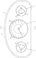
図1において、1はハウジングである。ハウジング1は、見返し部材及びケース体を有し、3個の指示計器、即ち、速度計2,燃料計3及び水温計4を収納するものである。速度計2は、燃料計3及び水温計4よりも大きく、燃料計3と水温計4の間に配置されている。速度計2は、表示板21及び指針22を有している。また、燃料計3及び水温計4は、文字板31,41及び指針32,42を夫々有している。文字板31,41は、透光性樹脂(例えばポリカーボネート)からなる基板に指標部3a,4aを除いて遮光部を印刷形成したものである。指針32,42はステッピングモータ(図示しない)により回動され、文字板31,41の指標部3a,4aを指示する。
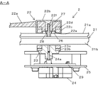
図2は要部拡大断面図である。速度計2は、表示板21,指針22,軸受け部23及びステッピングモータ(回転駆動部材)24を有している。また、25は回路基板であり、この回路基板25にステッピングモータ24が搭載されている。
表示板21は、透光性基板21aと、液晶表示素子(可変表示素子)21bとからなるものである。
透光性基板21aは、透光性樹脂(例えばアクリル、ポリカーボネート)からなり、指針22を回動可能に保持するための後述する支持部材が配設されるものである。
液晶表示素子21bは、透明電極膜が形成された一対の透光性基板に液晶を封入した液晶セルの両面に偏光板を貼り合わせたものであって、例えばドットマトリクス型の液晶表示素子である。液晶表示素子21bは、その表示内容を変更可能であって、少なくとも指標部2a及び文字部2bを表示可能なものである。
指針22は、指針本体22aと、指針キャップ22bと、第一の磁石22cと、第一のヨーク22dと、を有し、液晶表示素子22aにて表示される指標部2aを指示するものである。
指針本体22aは、ポリカーボネート等の透光性樹脂からなるものであり、回転中心部には指針キャップ22bが嵌め込まれている。また、指針本体22aの回転中心部には、第一の磁石22c及び第一のヨーク22dを嵌入させる凹部が設けられている。また、指針本体22aは、透光性基板21a上に配置されるLED(照明手段)26からの照明光を受光して指針本体22aを光輝させるための受光部22eを有する。受光部22eはリング状の第一の磁石22c及び第一のヨーク22dの空洞部に位置するように形成される。
指針キャップ22bは、例えばABS樹脂等の非透光性樹脂を略筒状に形成してなるものである。指針キャップ22bは、その内部に第一の磁石22c及び第一のヨーク22dを圧入保持するものである。なお、第一の磁石22c及び第一のヨーク22dの保持方法は異なるものであってもよく、指針キャップ22bの周縁部に突起を設け、第一の磁石22c及び第一のヨーク22dで前記突起を変形させて保持する方法や、指針キャップ22bの周縁部に第一の磁石22c及び第一のヨーク22dを係止するフック(係止手段)を形成する方法であってもよい。また、指針キャップ22bの中央部には、指針22を回動可能に支持する略円柱形の主軸27を挿入する挿入部22fが設けられている。28は主軸受け部であり、この主軸受け部28は透光性基板20に形成される凹部に配設され、主軸27を固定するものである。本実施形態においては、この主軸27と主軸受け部28とで指針22を回動可能に支持する支持部材が構成されている。
第一の磁石22cは、リング状に形成され、図3に示すようにS極及びN極が交互に複数着磁されてなるものである。なお、本実施形態においては4極が着磁されている。第一の磁石22cは、後述する第二の磁石23aと互いに吸引し合うものである。
第一のヨーク22dは、第一の磁石22cの第二の磁石23aと対向しない面(非対向面)側に設けられるものである。第一のヨーク22dは、第一の磁石22cの前記非対向面側からの漏れ磁束を抑制し、磁気効率を向上させる磁気回路を構成する。
軸受け部23は、第二の磁石23aと第二のヨーク23bとを有し、ステッピングモータ24の回動軸24aと嵌合されるものである。本実施形態における指針駆動手段は、軸受け部23とステッピングモータ24とからなるものである。
第二の磁石23aは、第一の磁石22cと対になるように第一の磁石22cに表示板21を介して対向する位置に配置され、ステッピングモータ24の回転駆動によって回転するものである。なお、図示しないが、第二の磁石23aも第一の磁石と同様にS極及びN極が交互に複数着磁されてなるものである。第二の磁石23aを設ける方法としては、軸受け部23をプラスティックマグネットで形成し、第一の磁石22cとの対向個所を着磁して形成する方法であってもよいし、また、軸受け部23とは別部材で第二の磁石23aを設けインサート成形あるいはアウトサート成形によって一体的に形成する方法であってもよい。
第二のヨーク23bは、第二の磁石23aの第一の磁石22cと対向しない面(非対向面)側に設けられるものである。第二のヨーク23bは、第二の磁石23aの前記非対向面からの漏れ磁束を抑制し、磁気効率を向上させる磁気回路を構成する。
また、回路基板25には、第二の磁石23aとステッピングモータ24との間に位置するように磁気シールド部材29が配置されている。本実施形態においては、ステッピングモータ24が回路基板25の裏面に配置され、磁気シールド部材29が回路基板25の表面に配置されている。なお、回路基板25及び磁気シールド部材29には孔部が設けられ、回動軸24aがこれらの孔部を介して回路基板25の表面側から突出している。磁気シールド部材29は、軟磁性材料(例えば鉄,ケイ素鋼板あるいはパーマロイ等)からなる。また、磁気シールド部材29は、第二の磁石23aの投影面積よりも大きくなるように形成されている。
本実施形態は、指針22に第一の磁石22cを設け、表示板21を介して第一の磁石22cに対向するように第二の磁石23aをステッピングモータ24の回動軸24aに固定される軸受け部23に設けたことにより、ステッピングモータ24の回転駆動によって第二の磁石23aを回転させると第一の磁石22cと第二の磁石23aとを磁力によって引きつけ合うことでステッピングモータ24の回転駆動に連動して指針22を回動させることができる。従って、従来の指針をステッピングモータに直接固定する方法のように表示板21の液晶表示素子21bに貫通孔を形成する必要がなく、表示板21を比較的安価に製造することができる。
さらに、第二の磁石23aと回転駆動部材であるステッピングモータ24との間に磁気シールド部材29を配置することによって、第一,第二の磁石22c,23aの磁界を遮断し、磁気影響がステッピングモータ24に及ぶことを低減できるため第一,第二の磁石22c,23aをステッピングモータ24に近接して配置する場合であっても指針の指示精度を向上させることが可能となる。また、磁気シールド部材29を第二の磁石23aの投影面積よりも大きくなるように形成すると、磁気シールド部材29の外周からの漏れ磁束を低減して磁気遮断効果を大きくすることができ、さらに好適である。
また、表示板21に透光性基板21aを備え、透光性基板21aに指針22を回動可能に支持する支持部材を配設することによって、液晶表示素子21bに対して指針22を支持するための加工を行う必要がなくなり、容易に指針22を配設可能であるとともに液晶表示素子21bをさらに安価に製造することが可能となる。
なお、第一,第二の磁石22c,23aは永久磁石であったが、例えば第二の磁石23aは電磁石であっても良い。また、可変表示素子としては、液晶表示素子21bのほかに有機EL素子であってもよく、またドットマトリクス型のほかにセグメント型であっても良い。また、表示板としては、例えば透光性樹脂に遮光部を印刷形成して指針22にて指示する固定表示部を形成した固定表示素子を有するものであってもよい。また、指針22を照明する照明手段としては、LED26に限定されるものではなく例えば表示板21に有機EL素子を適用し、この有機EL素子からの光を受光部22eに向けて発する構成であってもよい。また、指針駆動手段としてステッピングモータ24を備えるものであったが、ステッピングモータ24に代えて、例えば、交差コイル型ムーブメントを用いることができることは言うまでもない。
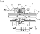
また、図4は、本発明の他の実施形態を示すものである。前述の実施形態との相違点は、磁気シールド部材30を回路基板25ではなく、軸受け部23に配設する点である。本実施形態においては、磁気シール部材30は磁気効率を向上させる第二のヨークを兼ねており、第二の磁石23aとともに回転する。かかる構成によっても本発明の効果を十分に得ることができる。
本発明は、指示計器装置に関し、磁石の吸引力によって指針と指針駆動手段とを固定する指示計器装置に好適である。
Claims (7)
- 表示板と、前記表示板の前面側に設けられた指針と、前記表示板の後面側に設けられ前記指針を回動させるための指針駆動手段と、を有する指示計器装置であって、前記指針に設けられる第一の磁石と、前記指針駆動手段に前記第一の磁石と対向するように設けられる第二の磁石と、前記指針駆動手段に備えられ前記第二の磁石を回転させる回転駆動部材と、前記第二の磁石と前記回転駆動部材との間に設けられる磁気シールド部材と、を備え、前記第一,第二の磁石の吸引力によって前記指針を前記指針駆動手段の回転駆動に連動して回動させることを特徴とする指示計器装置。
- 前記磁気シールド部材は、前記第二の磁石とともに回転するように設けられてなることを特徴とする請求項1に記載の指示器計器装置。
- 前記回転駆動部材が配設される回路基板を備え、前記磁気シールド部材は前記回路基板上に設けられてなることを特徴とする請求項1に記載の指示器計器装置。
- 前記磁気シールド部材は、前記第二の磁石の投影面積よりも大きく形成されてなることを特徴とする請求項1に記載の指示計器装置。
- 前記表示板は、前記指針に指示される可変表示部を備える可変表示素子を有してなることを特徴とする請求項1に記載の指示計器装置。
- 前記指針を回動可能に支持する支持部材を設けたことを特徴とする請求項1に記載の指示計器装置。
- 前記表示板は、前記支持部材が配設される透光性基板を有してなることを特徴とする請求項6に記載の指示計器装置。
Priority Applications (2)
| Application Number | Priority Date | Filing Date | Title |
|---|---|---|---|
| EP08869940.0A EP2239543A4 (en) | 2008-01-10 | 2008-12-16 | INSTRUMENT OF INDICATION |
| US12/811,325 US8365681B2 (en) | 2008-01-10 | 2008-12-16 | Indicating instrument |
Applications Claiming Priority (2)
| Application Number | Priority Date | Filing Date | Title |
|---|---|---|---|
| JP2008002947A JP2009162713A (ja) | 2008-01-10 | 2008-01-10 | 指示計器装置 |
| JP2008-002947 | 2008-01-10 |
Publications (1)
| Publication Number | Publication Date |
|---|---|
| WO2009087865A1 true WO2009087865A1 (ja) | 2009-07-16 |
Family
ID=40852990
Family Applications (1)
| Application Number | Title | Priority Date | Filing Date |
|---|---|---|---|
| PCT/JP2008/072799 WO2009087865A1 (ja) | 2008-01-10 | 2008-12-16 | 指示計器装置 |
Country Status (4)
| Country | Link |
|---|---|
| US (1) | US8365681B2 (ja) |
| EP (1) | EP2239543A4 (ja) |
| JP (1) | JP2009162713A (ja) |
| WO (1) | WO2009087865A1 (ja) |
Families Citing this family (3)
| Publication number | Priority date | Publication date | Assignee | Title |
|---|---|---|---|---|
| JP5007936B2 (ja) * | 2007-04-11 | 2012-08-22 | 日本精機株式会社 | 指示計器装置 |
| JP5354477B2 (ja) * | 2009-07-16 | 2013-11-27 | 日本精機株式会社 | 指示計器 |
| US20150035517A1 (en) * | 2013-07-30 | 2015-02-05 | Delphi Technologies, Inc. | Vehicle instrument panel with magnet equipped pointer |
Citations (2)
| Publication number | Priority date | Publication date | Assignee | Title |
|---|---|---|---|---|
| JPH0581643U (ja) * | 1992-04-06 | 1993-11-05 | 矢崎総業株式会社 | 自動車用メータ |
| JP2003161650A (ja) * | 2001-11-28 | 2003-06-06 | Nippon Seiki Co Ltd | 指示計器装置 |
Family Cites Families (24)
| Publication number | Priority date | Publication date | Assignee | Title |
|---|---|---|---|---|
| US2371511A (en) * | 1943-02-23 | 1945-03-13 | Gen Electric | Magnetic transmission |
| US3776176A (en) * | 1972-03-15 | 1973-12-04 | Master Electronics Corp | Indicator device which can be illuminated |
| US4016827A (en) * | 1975-09-12 | 1977-04-12 | Lawrence Jr James F | Magnetically coupled indicator means for control setting |
| US4090131A (en) * | 1976-07-26 | 1978-05-16 | Mas Joseph A | Moving magnet meter having a closed magnetic circuit rotor |
| DE2709412A1 (de) * | 1977-03-04 | 1978-09-07 | Max Baermann | Wirbelstromtachometer mit temperaturkompensation |
| US4195518A (en) * | 1978-11-07 | 1980-04-01 | Fisher & Porter Company | Armored rotameter |
| US4878453A (en) * | 1987-03-16 | 1989-11-07 | Yazaki Corporation | Indicating instrument for automotive vehicle |
| DE3839547A1 (de) * | 1988-11-24 | 1990-05-31 | Vdo Schindling | Wirbelstrommesswerk |
| US4891987A (en) * | 1988-11-25 | 1990-01-09 | Stockton William E | Magnetic linkage for bourdon tube gauges |
| JPH0344624A (ja) | 1989-07-12 | 1991-02-26 | Matsushita Electric Ind Co Ltd | 液晶表示装置 |
| JPH0581643A (ja) | 1991-09-19 | 1993-04-02 | Hitachi Maxell Ltd | 磁気記録媒体 |
| JP3300995B2 (ja) * | 1993-06-04 | 2002-07-08 | 矢崎総業株式会社 | 車両用表示装置 |
| JP3846034B2 (ja) * | 1997-11-20 | 2006-11-15 | 株式会社デンソー | 軸受け |
| DE10043950A1 (de) * | 2000-02-23 | 2002-03-21 | Mannesmann Vdo Ag | Anzeigevorrichtung mit einem Zeiger |
| US6624608B2 (en) * | 2001-02-23 | 2003-09-23 | Denso Corporation | Indicating instrument for a vehicle |
| CA2513849A1 (en) * | 2004-07-29 | 2006-01-29 | Dwyer Instruments, Inc. | Gauge having a magnetically driven pointer rotation device |
| JP4458988B2 (ja) * | 2004-08-31 | 2010-04-28 | 日本精機株式会社 | マグネットロータおよびそのマグネットロータを備えた可動磁石式計器、そのマグネットロータを備えたステッピングモータ |
| JP4687246B2 (ja) * | 2005-05-31 | 2011-05-25 | パナソニック株式会社 | 回転型電子部品 |
| JP5099421B2 (ja) * | 2007-03-21 | 2012-12-19 | 日本精機株式会社 | 指示計器装置 |
| JP5007936B2 (ja) * | 2007-04-11 | 2012-08-22 | 日本精機株式会社 | 指示計器装置 |
| JP5035531B2 (ja) * | 2007-04-18 | 2012-09-26 | 日本精機株式会社 | 車両用表示装置 |
| JP5105067B2 (ja) * | 2008-01-30 | 2012-12-19 | 日本精機株式会社 | 計器装置 |
| US7810444B2 (en) * | 2008-08-28 | 2010-10-12 | Delphi Technologies, Inc. | Configurable gauge apparatus including a flat panel display and a mechanical pointer |
| DE102010038241B9 (de) * | 2009-10-30 | 2017-07-13 | Denso Corporation | Anzeigeinstrumentensystem mit einer Anzeigeeinrichtung für ein Fahrzeug |
-
2008
- 2008-01-10 JP JP2008002947A patent/JP2009162713A/ja active Pending
- 2008-12-16 US US12/811,325 patent/US8365681B2/en not_active Expired - Fee Related
- 2008-12-16 EP EP08869940.0A patent/EP2239543A4/en not_active Withdrawn
- 2008-12-16 WO PCT/JP2008/072799 patent/WO2009087865A1/ja active Application Filing
Patent Citations (2)
| Publication number | Priority date | Publication date | Assignee | Title |
|---|---|---|---|---|
| JPH0581643U (ja) * | 1992-04-06 | 1993-11-05 | 矢崎総業株式会社 | 自動車用メータ |
| JP2003161650A (ja) * | 2001-11-28 | 2003-06-06 | Nippon Seiki Co Ltd | 指示計器装置 |
Also Published As
| Publication number | Publication date |
|---|---|
| EP2239543A4 (en) | 2013-06-19 |
| JP2009162713A (ja) | 2009-07-23 |
| EP2239543A1 (en) | 2010-10-13 |
| US8365681B2 (en) | 2013-02-05 |
| US20100288183A1 (en) | 2010-11-18 |
Similar Documents
| Publication | Publication Date | Title |
|---|---|---|
| JP5099421B2 (ja) | 指示計器装置 | |
| WO2009087865A1 (ja) | 指示計器装置 | |
| JP2003161650A (ja) | 指示計器装置 | |
| EP2146187B1 (en) | On-vehicle display device | |
| WO2009096105A1 (ja) | 計器装置 | |
| JP5007936B2 (ja) | 指示計器装置 | |
| JP2009174877A (ja) | 指示計器装置 | |
| US20140000508A1 (en) | Needle indicator oriented by periphery electromagnets | |
| JP2008268138A (ja) | 指示計器装置 | |
| WO2009131039A1 (ja) | 指示計器装置 | |
| WO2002009073A1 (fr) | Element d'affichage et dispositif d'affichage utilisant ledit element d'affichage | |
| JP5141888B2 (ja) | 計器装置 | |
| JP2008268117A (ja) | 指示計器装置 | |
| WO2009110322A1 (ja) | 計器装置 | |
| JP2009222599A (ja) | 計器装置 | |
| JP2009210453A (ja) | 計器装置 | |
| JP2010048687A (ja) | 計器装置 | |
| JP2009271003A (ja) | 計器装置 | |
| JP2003214914A (ja) | 文字板およびその製造方法並びにメータ | |
| JP2006078433A (ja) | 計器装置 | |
| JP2010164392A (ja) | 表示装置 | |
| JP2013195248A (ja) | 指針式計器 | |
| JP2006010419A (ja) | 表示装置 | |
| JP2006038659A (ja) | 計器装置 |
Legal Events
| Date | Code | Title | Description |
|---|---|---|---|
| 121 | Ep: the epo has been informed by wipo that ep was designated in this application |
Ref document number: 08869940 Country of ref document: EP Kind code of ref document: A1 |
|
| WWE | Wipo information: entry into national phase |
Ref document number: 12811325 Country of ref document: US |
|
| NENP | Non-entry into the national phase |
Ref country code: DE |
|
| WWE | Wipo information: entry into national phase |
Ref document number: 2008869940 Country of ref document: EP |