WO2009087736A1 - 放電ランプ及び照明装置 - Google Patents
放電ランプ及び照明装置 Download PDFInfo
- Publication number
- WO2009087736A1 WO2009087736A1 PCT/JP2008/003969 JP2008003969W WO2009087736A1 WO 2009087736 A1 WO2009087736 A1 WO 2009087736A1 JP 2008003969 W JP2008003969 W JP 2008003969W WO 2009087736 A1 WO2009087736 A1 WO 2009087736A1
- Authority
- WO
- WIPO (PCT)
- Prior art keywords
- arc tube
- bulb
- light bulb
- holding member
- tube
- Prior art date
Links
Images

Classifications
-
- H—ELECTRICITY
- H01—ELECTRIC ELEMENTS
- H01J—ELECTRIC DISCHARGE TUBES OR DISCHARGE LAMPS
- H01J61/00—Gas-discharge or vapour-discharge lamps
- H01J61/02—Details
- H01J61/30—Vessels; Containers
- H01J61/32—Special longitudinal shape, e.g. for advertising purposes
- H01J61/327—"Compact"-lamps, i.e. lamps having a folded discharge path
-
- H—ELECTRICITY
- H01—ELECTRIC ELEMENTS
- H01J—ELECTRIC DISCHARGE TUBES OR DISCHARGE LAMPS
- H01J61/00—Gas-discharge or vapour-discharge lamps
- H01J61/96—Lamps with light-emitting discharge path and separately-heated incandescent body within a common envelope, e.g. for simulating daylight
-
- Y—GENERAL TAGGING OF NEW TECHNOLOGICAL DEVELOPMENTS; GENERAL TAGGING OF CROSS-SECTIONAL TECHNOLOGIES SPANNING OVER SEVERAL SECTIONS OF THE IPC; TECHNICAL SUBJECTS COVERED BY FORMER USPC CROSS-REFERENCE ART COLLECTIONS [XRACs] AND DIGESTS
- Y02—TECHNOLOGIES OR APPLICATIONS FOR MITIGATION OR ADAPTATION AGAINST CLIMATE CHANGE
- Y02B—CLIMATE CHANGE MITIGATION TECHNOLOGIES RELATED TO BUILDINGS, e.g. HOUSING, HOUSE APPLIANCES OR RELATED END-USER APPLICATIONS
- Y02B20/00—Energy efficient lighting technologies, e.g. halogen lamps or gas discharge lamps
Definitions
- the present invention relates to a technique for improving luminous flux rise characteristics.
- a bulb-type fluorescent lamp which is a kind of low-pressure mercury discharge lamp as a discharge lamp, is an arc tube in which mercury is enclosed in a glass tube and a fluorescent layer is formed on the inner peripheral surface of the glass tube, and a holder for holding the arc tube And a lighting unit for emitting light from the arc tube.
- Light bulb-type fluorescent lamps have higher lamp efficiency than ordinary light bulbs and are widely used as energy-saving light sources.
- the luminous flux rise characteristics at the start of lighting are worse than general light bulbs, and various studies have been made to improve the characteristics. Has been made.
- the amount of the sticking agent used is increased as compared with the case where only the arc tube is fastened. Work becomes necessary, and it becomes expensive as a discharge lamp.
- the present invention has been made in view of the above-described problems, and is a discharge lamp that can improve the luminous flux rise characteristic at the start of lighting and can reduce the cost and improve the workability by reducing the amount of the sticking agent used.
- the purpose is to provide.
- a discharge lamp includes a light emitting tube that discharges light, a light emitter that has better characteristics than a luminous flux rise characteristic at the time of starting a lamp in the light emitting tube, the light emitting tube, and the light emitting device.
- a first fixing agent that fixes the light emitting tube and the holding member to each other, and a second fixing member that fixes the light emitting body and the holding member to each other. It is characterized by being connected to an adhesive.
- the lighting device includes a discharge lamp and a lighting fixture that is mounted to light up the discharge lamp, and the discharge lamp is a discharge lamp having the above-described configuration.
- the first fixing agent that fixes the arc tube and the holding member is connected to the second fixing agent that fixes the luminous body and the holding member.
- the heat of the luminous body can be transmitted to the arc tube side through the first and second fixing agents.
- the arc tube has a swivel portion having a shape swiveled around an imaginary axis, and the light emitter is surrounded by the swivel portion.
- the luminous body emits a luminous flux within a range of 20% or more and 40% or less with respect to the luminous flux emitted from the arc tube during steady lighting, or the luminous body is characterized in that It is characterized by being a light bulb having a filament coil.
- the lighting device according to the present invention includes the discharge lamp having the above-described configuration, it is possible to improve the light beam rising characteristics at the start of lighting and to reduce the amount of use of the sticking agent and improve the workability. .
- FIG. 1 It is a figure which shows the edge part of the arc_tube
- FIG. 1 It is a schematic perspective view of the holding member which concerns on a modification, (a) is the figure seen from the side in which most arc tube main bodies are located, (b) is the figure seen from the side in which a board
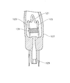
- FIG. 1 is a longitudinal sectional view of a light bulb shaped fluorescent lamp according to this embodiment.
- the light bulb-type fluorescent lamp 1 includes a light emitting tube 3, an auxiliary light bulb (corresponding to a “light emitter” in the present invention) 4, and a holding member 5 that holds the light emitting tube 3 and the auxiliary light bulb 4.
- a lighting unit 7 mounted on the holding member 5 on the side opposite to the side where the arc tube 3 and the auxiliary light bulb 4 are located, and for emitting (lighting) the arc tube 3 and the auxiliary light bulb 4;
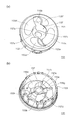
- FIG. 2 is a schematic view of the arc tube according to the present embodiment. A part of the glass tube 13 is cut away so that the inside of the arc tube 3 can be seen.
- the arc tube 3 includes an arc tube main body 31 formed by bending the glass tube 13 and an electrode 33 sealed at the ends 3 a and 3 b of the arc tube main body 31.
- FIG. 2 only the electrode 33 at one end 3 a of the arc tube 3 appears, but the electrode having the same configuration is also sealed at the other end 3 b of the arc tube 3.
- the end portion of the arc tube body 31 and the end portion of the glass tube 13 are also end portions 3a and 3b of the arc tube 3, and "3a" and "3b" are used as reference numerals of these end portions.
- the arc tube main body 31 has a central portion of the glass tube 13 on the virtual pivot axis A (this central portion is also referred to as “the tip portion of the arc tube”, and the symbol “3c” is used). Both side portions have a double spiral shape that revolves around the revolving axis A in a certain direction (“B” in FIG. 2) with a constant turning radius.
- the arc tube main body 31 is swung around the swivel axis A while moving in a certain direction along the swivel axis A (for example, downward in FIG. 2).
- the arc tube body may be composed of one glass tube or a plurality of glass tubes.
- the first turning portion 31a and the second turning portion 31b have the same turning pitch (the amount of movement on the turning axis A during one turn around the turning axis A, which is “P1” in the figure). .) And the distance between the axis of the glass tube 13 constituting the first turning part 31a and the axis of the glass tube 13 constituting the second turning part 31b ( "P2" in the figure) is substantially constant except for the vicinity of the end portions 3a and 3b of the arc tube main body 31 (for example, the portion inserted into the holding member 5 in the arc tube 3). is there. In addition, the dimension line of P1, P2 in FIG. 2 passes the center (axial center) of the glass tube 13 in each turning part 31a, 31b. Note that the turning pitch may be constant, may change, or may change with a certain regularity.
- the number of turns turning around the turning axis A is determined by lamp specifications (rated power, etc.), and the glass tube 13 in the vicinity of the ends 3a, 3b of the arc tube body 31 is in the direction in which the turning axis A extends. Is swiveled around the swivel axis A so that the gap between the adjacent glass tubes 13 is widened.
- a phosphor layer 35 is formed on the inner surface of the arc tube main body 31 (glass tube 13).
- the phosphor layer 35 includes one or more kinds of phosphors, for example, rare earth phosphors.
- the arc tube body 31 is filled with mercury, which is a luminescent material, or a rare gas as a buffer gas.
- the electrode 33 includes a filament coil 41 and a pair of lead wires 43 and 45 that support the filament coil 41 (hold the erected state), and the pair of lead wires 43 and 45. Is held by a bead glass 47 (bead glass type). If the bead glass 47 is located outside the arc tube body 31, the bead glass 47 may be removed after the electrode 33 is sealed to the arc tube body 31, or may remain as it is. Of course, it may exist in the arc tube main body 31.
- the filament coil 41 is made of, for example, a tungsten wire made into a double winding (coiled) and filled with an electron emitting material.
- the lead wires 43 and 45 may be integrated by connecting a plurality of metal wires, or may be a single metal wire used as it is.
- the electrode 33 is a portion of the pair of lead wires 43 and 45 located between the bead glass 47 and the filament coil 41, and the end 3a of the arc tube body 31 is pinched (crush sealed). Thus, the arc tube body 31 is sealed.
- FIG. 3 is a schematic diagram of an auxiliary light bulb according to the present embodiment.
- the auxiliary light bulb 4 is turned on at the time of starting when the light bulb shaped fluorescent lamp 1 is turned on (so-called “lighting start time”), and is, for example, a filament light bulb having a filament coil 51. Yes, it has better characteristics than the luminous flux rising characteristics of the arc tube 3.
- the auxiliary light bulb 4 includes a glass bulb 50 and a stem 52 that holds the filament coil 51, and the stem 52 is sealed to the glass bulb 50.
- the glass bulb 50 has a cylindrical shape (the cross-sectional shape is circular).
- the cross-sectional shape is circular.
- members such as the stem 52 inside are indicated by solid lines.
- the stem 52 includes a filament coil 51, a pair of lead wires 53 and 54 that supply power to the filament coil 51 and holds the filament coil 51, and the glass bulb 50 after the stem 52 is stem-sealed to the glass bulb 50.
- a narrow tube 55 for exhausting the inside and a flare 56 for holding the narrow tube 55 and the pair of lead wires 53 and 54 are provided.
- the filament coil 51 for example, a tungsten wire made of a double winding (coiled) is used, and as shown in FIG. 3, a central portion 51c (the center in the coil axis direction) is used. It bends as a whole and has an inverted “V” shape spreading toward the opening side of the glass bulb 50, and its end portions 51 a and 51 b are attached to a pair of lead wires 53 and 54.
- a hanging tool 57 that locks the central portion 51c of the filament coil 52 and suspends the filament coil 51 is provided at an end portion of the narrow tube 55 that is located in the glass bulb 50. Yes.
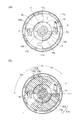
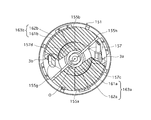
- FIG. 4 is a perspective view of the holding member according to the present embodiment, (a) is a view as seen from the side where most of the arc tube is located, and (b) is the position of the substrate. It is the figure seen from the side to do.
- the holding member 5 includes, for example, a peripheral wall 15 and an end wall 17 that closes one end thereof, and has a cylindrical shape with the one end closed.
- the end wall 17 has receiving ports 17 a and 17 b for receiving the end portions 3 a and 3 b of the arc tube 3 into the holding member 5, and end portions 3 a and 3 b of the arc tube 3.
- the guide grooves 17c and 17d for guiding to the receiving ports 17a and 17b, the covering portions 17e and 17f for covering the ends 3a and 3b of the arc tube 3 received from the receiving ports 17a and 17b, and the auxiliary light bulb 4 are held.
- a bulb holder 18 is formed.
- the light bulb holding part 18 has an outer peripheral contact part 18 a that contacts an outer peripheral part located on the sealing part side of the auxiliary light bulb 4, and an end part (bottom part of the auxiliary light bulb 4) located on the sealing part side of the auxiliary light bulb 4. And a bottom abutting portion 18b that abuts.
- the outer peripheral abutting portion 18a includes a recessed portion that is recessed from the central portion of the end wall 17 toward the base side, and a protruding portion that protrudes from the periphery of the recessed portion toward the distal end portion 3c side of the arc tube 3 It is configured.
- the inner peripheral surface shapes of the recessed portion and the protruding portion correspond to the glass bulb 50 of the auxiliary light bulb 4 (corresponding to the outer peripheral shape in the cross section of the glass bulb 50). ), In a plan view (when viewed from the direction in which the turning axis A of the arc tube 3 extends).
- a through hole 18c for guiding the pair of lead wires 53 and 54 of the auxiliary light bulb 4 to the inside of the holding member 5 (the back side of the end wall 17) is formed in the bottom contact portion 18b (and the outer periphery contact portion 18a).
- 18 d is formed, and a through hole 18 e is formed in the bottom contact portion 18 b so that the thin tube 55 of the auxiliary light bulb 4 does not buffer the holding member 5.
- the through holes 18 d and 18 c provided in the bottom contact portion 18 b are located between the pair of receiving ports 17 a and 17 b formed in the end wall 17.
- FIG. 5 is a view seen from the back side of the holding member for explaining the holding state of the arc tube and the auxiliary bulb, (a) shows a state before the arc tube and the auxiliary bulb are fixed, and (b). Indicates a state in which the arc tube and the auxiliary light bulb are fixed with a fixing agent.
- the arc tube 3 is held in a state where the ends 3a and 3b of the arc tube 3 are received from the receiving ports 17a and 17b of the holding member 5 (FIG. 5).
- the end portions 3a and 3b of the arc tube 3 correspond to the fixing agent (corresponding to the “first fixing agent” of the present invention, for example, a silicone resin) 19a and 19b. Is fixed to the inner surface (the back surface of the end wall 17 or the inner surface of the peripheral wall 15).
- the auxiliary light bulb 4 is held in a state where the end portion (end portion on the stem sealing portion side) of the auxiliary light bulb 4 is inserted into the light bulb holding portion 18 (FIG. 5A).
- the lower end portion of 4 is an adhesive (corresponding to the “second adhesive” of the present invention, for example, silicone resin) 20a, 20b, and the inner surface of the holding member 5 (the back surface of the end wall 17) or the light bulb holder 18. This is performed by being fixed to the inner surface (the outer peripheral contact portion 18a and / or the bottom contact portion 18b).
- the through holes 18c and 18d are formed along the circumferential direction with the center of the bulb holding portion 18 (this center is also the center of the holding member 5) as a reference, and one ends thereof are the receiving ports 17a and 17b. The other end substantially coincides with the end of the arc tube 3 inserted from the receiving ports 17a and 17b. That is, the through holes 18 c and 18 d are formed corresponding to the end portions 3 a and 3 b of the arc tube 3 inserted into the holding member 5.
- the fixing agents 20a and 20b are introduced into the bulb holder 18 using the through holes 18c and 18d, and the outer periphery of the lower side of the auxiliary bulb 4 is inserted.
- the fixing agent 20a, 20b is filled in the gap between the surface and the inner peripheral surface of the bulb holder 18.
- the fixing agents 19a and 19b are introduced so as to cover the end portions 3a and 3b of the arc tube 3.
- the fixing agent 20a, 20b fixing the auxiliary light bulb 4 and the arc tube 3 are fixed.
- a single lump connected to the fixing agents 19a and 19b is formed corresponding to each of the receiving ports 17a and 17b (integrated, and the integrated ones are denoted by "21a" and "21b". Indicated by
- the sticking agents 21a and 21b come into contact with both the end portions 3a and 3b of the arc tube 3 and the auxiliary light bulb 4, and the heat generated in the auxiliary light bulb 4 is easily transferred to the arc tube 3 to light up.
- the temperature rise of the arc tube 3 at the time of starting can be accelerated.
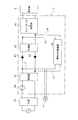
- FIG. 6 is a configuration diagram of the lighting unit according to the present embodiment.
- the lighting unit 7 mainly includes a rectifier 61, a smoother 62, a switching + stabilizer 63, a light bulb lighting controller 64, and the like.
- a series inverter type circuit is used for the switching + ballast for lighting the arc tube 3.
- an example of the lighting unit 7 will be described.
- the rectifier 61 rectifies commercial low-frequency alternating current and converts it into direct current, and includes, for example, four diode bridge elements.
- the smoother 62 smoothes the direct current output from the rectifier 61, and includes, for example, electrolytic capacitors C1 and C2 (a so-called voltage doubler rectifier).
- the lighting unit 7 is connected to a commercial low-frequency AC power source via the base 23.
- diodes D ⁇ b> 1 and D ⁇ b> 2 are connected to prevent a backflow of current from the smoother 62 to the rectifier 61.
- the switching + stabilizer 63 uses the output from the smoother 62 to supply high-frequency power to the arc tube 3 or stabilize a change in current generated in the arc tube 3 that is lit.
- the switching action is achieved by, for example, a pair of switching elements (eg, transistors) or a coupling capacitor, and the stabilizing action is achieved by a choke coil, a resonance capacitor, or the like.
- an IC chip is used.
- the pair of switching elements described above are integrated.
- the choke coil for the ballast and the resonance capacitor also constitute a resonance circuit for lighting the arc tube 3 (dielectric breakdown).
- the auxiliary light bulb 4 is turned on via wirings (feeding paths) L1 and L2 connected to the output side of the rectifier 61, and the light on / off control is performed by the light bulb lighting controller 64.
- the light bulb lighting controller 64 is connected to the output side of the smoother 62 via the wirings L3 and L4.
- a predetermined condition for example, 60 (sec) has elapsed after the start of lighting
- an auxiliary light bulb is provided. Stop supplying power to 4 and turn it off.
- a thermal fuse 66 is connected between the rectifier 61 and the base 23. For example, when the ambient temperature in the case 9 and circuit components rise excessively, power supply to the rectifier 61 is stopped. I am doing so. As an excessive temperature rise, when a predetermined time elapses after the start of lighting, the auxiliary light bulb 4 that should be turned off is continuously turned on without turning off, or the electrode 33 in the arc tube 3 is approaching the end of life. There are cases.
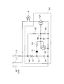
- FIG. 7 is a circuit diagram of the light bulb lighting controller.
- the light bulb lighting controller 64 includes, for example, two transistors Q1 and Q2, a resistor R1, a capacitor C4, and the like, and the auxiliary light bulb 4 is turned on / off in the on / off state of the transistor Q1.
- the transistor Q1 connected to the auxiliary light bulb 4 is turned on and the auxiliary light bulb 4 is turned on.
- the partial pressure of the connection node N1 becomes a predetermined value.
- the transistor Q1 (which is a switching element) is turned off, and the auxiliary light bulb 4 is turned off.
- the auxiliary light bulb 4 has one lead wire connected to the wiring L1 and the other lead wire connected to the drain of the transistor Q1.
- the transistor Q1 has a source connected to the wiring L4 (L2) and a gate connected to the collector of the transistor Q2.
- the base of the transistor Q2 is connected to the connection node N1 via the resistor R4 and the Zener diode Z1, and the emitter of the transistor Q2 is connected to the wiring L2.
- the connection node N1 is connected to the wiring L3 through the resistor R1 and the connection node N3, and is connected to the wiring L4 (L2) through the capacitor C4.
- connection node N2 between the collector of the transistor Q2 and the gate of the transistor Q1 is connected to the connection node N3 on the input side of the resistor R1 connected to the wiring L3 via the resistor R2, and to the wiring L2 via the resistor R3. , Each connected.
- the resistors R2 and R3 are for adjusting the voltage at the connection node N2.
- the auxiliary light bulb 4 is turned on by being supplied with power from the wiring L1, and in accordance with this, electric charges are gradually accumulated in the capacitor C4. At this time, the transistor Q1 is in an on state.
- the Zener diode Z1 breaks down and the transistor Q2 is turned on. Thereby, the transistor Q1 is turned off and the auxiliary light bulb 4 is turned off.
- the light bulb lighting controller 64 uses the charging time of the capacitor C4, and the time from the start of lighting to the extinguishing of the auxiliary light bulb 4 can be set by the capacity of the capacitor C4 and the resistance value of the resistor R1. .
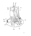
- FIG. 8 is a perspective view of the lighting unit.
- a choke coil CH is mounted on the substrate 22 at the center, and the IC chip IC is placed at a predetermined interval (for example, about 4 mm) with respect to the choke coil CH.
- the IC chip IC has a plurality of leads ICa and ICb, and these leads ICa and ICb penetrate the substrate 22 and have their back surfaces (the surface on which the choke coil CH is mounted on the substrate 22 being the front surface). It is fixed with solder or the like.
- the two electrolytic capacitors C1 and C2 are mounted on the substrate 22 via lead wires so that the main body portions C1a and C2a are located above the choke coil CH.
- a thermal fuse 66 is disposed between the IC chip IC and the choke coil CH, and the thermal fuse 66 extends from the IC chip IC (not shown in FIG. 8). Touching. For example, when the auxiliary light bulb 4 is lit even after a predetermined time has elapsed, the heat on the auxiliary light bulb 4 side can be transferred from the lead to the thermal fuse 66.
- the choke coil CH is saturated and the temperature rises. Since the temperature fuse 66 is arranged in the vicinity of the choke coil CH, this heat (temperature) is also detected. When this temperature exceeds a predetermined value, the thermal fuse 66 is blown, and the power supply to the rectifier 61 is stopped.
- Attachment of the substrate 22 to the holding member 5 is performed, for example, from the opening edge of the peripheral wall 15 of the holding member 5 as shown in FIG. (A vertical direction in FIG. 1, which coincides with the extending direction of the turning axis A.)
- FIG. A vertical direction in FIG. 1, which coincides with the extending direction of the turning axis A.
- a plurality of locking arms 15 a extending in a direction parallel to the axis of the holding member 5 are engaged with the peripheral edge of the substrate 22.
- the case 9 has, for example, a cone shape, a large-diameter cylindrical portion 9 a, a small-diameter cylindrical portion 9 b having a smaller diameter than the large-diameter cylindrical portion 9 a, and a large-diameter cylinder. And an inclined cylindrical portion 9c that connects the portion 9a and the small diameter cylindrical portion 9b.
- the case 9 and the holding member 5 are attached to the inner peripheral surface of the case 9 with an engaging protrusion 15 c formed on the outer surface of the peripheral wall 15 of the holding member 5. This is done by engaging with the engaging recess 9d.
- the engagement protrusion 15c is formed in a hook shape around the entire periphery of the holding member 5, but a plurality of the periphery may be formed at equal intervals in the circumferential direction.
- a plurality of, for example, four locking recesses 9d are formed at equal intervals in the circumferential direction of the case 9.
- the engagement protrusion and the locking recess may be engaged with each other, and may be provided on either the case or the holding member.
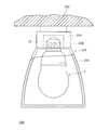
- (6) Globe for example, an A-shaped globe 11 is used, and the opening-side end 11a of the globe 11 is inserted in the gap between the case 9 and the holding member 5, and The case 9 and the holding member 5 are fixed to each other by a fixing agent 25 filled in the gap, for example, a silicone resin.
- the heat connecting member 27 is for transmitting the heat of the arc tube 3 to the globe 11 when the arc tube 3 is lit, and for reducing the temperature of the arc tube 3.
- a diffusion film 28 mainly composed of calcium carbonate is applied to the inner surface of the globe 11. 2.
- Example An example of the arc tube according to the above embodiment will be described.
- the glass tube 13 constituting the arc tube body 31 is made of a lead-free glass material.
- the inner diameter D1 is 5.9 (mm) and the outer diameter D2 is 7.5 ( mm), and the turning radius at which the central axis of the glass tube 13 turns around the turning axis A is about 12.8 (mm).
- a double spiral arc tube main body 31 having an outer diameter D3 of about 33 (mm) is obtained.
- the total number of turns of the first and second turning parts 31a and 31b turning around the turning axis A is 5 times.
- the turning pitch P1 of the first turning part 31a and the second turning part 31b is 18 (mm), and it is between the axis of the first turning part 31a and the axis of the second turning part 31b.
- the distance P2 is 9 (mm). That is, the gap between the glass tubes 13 adjacent to each other in the extending direction of the swivel axis A (the narrowest gap between the outer circumferences of the adjacent glass tubes 13) is 1.5 (mm).
- red Y 2 O 3 : Eu
- blue BaMg 2 Al
- Y 2 O 3 Eu
- Eu Eu
- Eu Eu
- Mn rare earth phosphors emitting 16 O 27 : Eu, Mn
- the mercury sealed in the arc tube body 31 is 1 (mg), and the rare gas is a mixed gas of argon and krypton, and is sealed at 550 (Pa).
- the distance between the central axes of the filament coils 41 in the discharge space 48 is 400 (mm).
- the amount of insertion of the end portions 3a and 3b of the arc tube 3 into the holding member 5 is 1/4 turn as shown in FIG. That is, from the edge of the receiving ports 17a and 17b to a position rotated by 90 degrees along the circumferential direction with respect to the center O of the holding member 5, the through holes 18c and 18d of the bulb holding part 18 are also It is provided corresponding to the end portions 3 a and 3 b of the arc tube 3 in the holding member 5.
- the fixing members 20a and 20b for fixing the end portions 3a and 3b of the arc tube 3 and the auxiliary light bulb 4 are held from the end edges of the receiving ports 17a and 17b. 5 from the position returned by 45 degrees in the direction opposite to the direction in which the end portions 3a and 3b of the arc tube 3 are inserted, from the center O of the arc tube 3 to the tips of the end portions 3a and 3b of the arc tube 3 It is provided in the area.
- FIG.5 (b) the area
- the bulb-type fluorescent lamp has an input to the arc tube 3 (so-called lamp input) of 10 (W), and the luminous flux at the time of rating is 810 (lm), which is the same as that of the general incandescent bulb 60W.
- the input to the auxiliary light bulb 4 is 20 (W), and the luminous flux at the rated time at this time is 200 (lm).
- invention product The bulb-type fluorescent lamp according to the present invention described in the above embodiment (hereinafter referred to as “invention product”) and the bulb-type fluorescent lamp having only the arc tube without the auxiliary bulb 4. (In order to distinguish it from the above-described invention product, hereinafter, it is referred to as “conventional product”) and a comparative test of the rising characteristics of the light beam until 5 minutes have passed since the start of lighting was performed.
- the environmental conditions for the test were ambient temperature of 5 (° C.). Under this condition, a bulb-type fluorescent lamp was lit on the base.
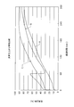
- FIG. 9 is a diagram showing a comparison result of the light beam rising characteristics.
- a in the figure indicates the rise characteristic of the invention
- B in the figure indicates the rise characteristic of the light bulb-type fluorescent lamp having no light emitter (auxiliary light bulb).
- the vertical axis in the figure is the ratio to the luminous flux during steady lighting, and 100 (%) indicates the luminous flux during steady lighting (810 (lm) in this embodiment).
- the horizontal axis in the figure is the elapsed time from the start of lighting.
- the invention product is obtained by integrally fixing the end portions 3a, 3b of the arc tube 3 and the lower end portion of the auxiliary light bulb 4 with fixing agents 21a (19a, 20a), 21b (19b, 20b).
- the luminous flux increases with time and reaches about 80% of the luminous flux during steady lighting after about 300 (Sec) from the start of lighting. ing.
- the time for the invention product to reach 80 (%) from the start of lighting is 240 (Sec). That is, the time from the start of lighting until it reaches 80 (%) is shorter in the product of the present invention, and the light beam rise characteristic is improved by about 20% as compared with the light bulb type fluorescent lamp not having the auxiliary light bulb.
- the cause of the improvement of the luminous flux rising characteristic is that the auxiliary light bulb is provided and the glass tube constituting the arc tube is configured to rotate around the auxiliary light bulb.
- the temperature of the arc tube is heated by the heat generated when the auxiliary light bulb emits light, the temperature inside the arc tube increases, and as a result, the mercury vapor pressure rises, improving the luminous flux rising characteristics.
- the rise of the luminous flux in the invention is compared to the light bulb type fluorescent lamp in which the fixing agents 19a and 19b for fixing the arc tube and the holding member and the fixing agents 20a and 20b for fixing the auxiliary light bulb and the holding member are not connected. It has been confirmed by experiments that the time is improved by about 5% until almost 300 (Sec) elapses after the start of lighting.
- the product according to the invention it reaches 30 (%) of the luminous flux at the time of steady lighting immediately after starting lighting. This is due to the luminous flux of the auxiliary light bulb 4 that is turned on at the start of lighting. 3.
- Auxiliary light bulb In the present embodiment, the luminous flux of the arc tube is 810 (lm), and the luminous flux of the auxiliary light bulb is 200 (lm). In the embodiment, the luminous flux of the auxiliary bulb has not been described. However, it is preferable to emit a luminous flux in the range of 20% or more and 40% or less with respect to the luminous flux of the arc tube (during steady lighting). .
- the gap between the glass tube of the first swivel part 31a adjacent to the swivel axis direction and the glass tube of the second swivel part was 1.5 (mm). However, this gap is preferably 0.5 (mm) or more and 5 (mm) or less.
- the present invention has been described based on the embodiments, the content of the present invention is not limited to the specific examples shown in the above embodiments. For example, the following modifications are possible. Can be implemented. 1. In the embodiment, a so-called A-shaped light bulb-type fluorescent lamp has been described. However, other types of light-bulb fluorescent lamps may be used. As another example, the shape of the globe is, for example, G-shaped.
- a so-called D-shaped bulb-type fluorescent lamp without a globe may be used.
- FIG. 10 is a view showing a longitudinal section of a D-shaped bulb-type fluorescent lamp.
- the bulb-type fluorescent lamp 101 includes an arc tube 3, an auxiliary bulb 4, a holding member 105 that holds the arc tube 3 and the auxiliary bulb 4, and the arc tube 3 and the auxiliary bulb 4 in the holding member 105.
- the lighting unit 7 for emitting (lighting) the arc tube 3 and the auxiliary light bulb 4, and the case in which the lighting unit 7 is housed and attached to the holding member 5 109.
- the D-shaped bulb-type fluorescent lamp 101 has substantially the same configuration as the bulb-type fluorescent lamp 1 described in the embodiment except that the holding member 105 and the case 109 are different.
- the holding member 105 has a bottomed cylindrical shape including a cylindrical peripheral wall 105b and an end wall 105a that closes one end of the peripheral wall 105b.
- the end wall 105a is formed with a receiving port for receiving the arc tube 3 therein, a light bulb holding portion for holding the auxiliary light bulb 4, and the like.
- the peripheral wall 105 b is fixed by, for example, a fixing agent 111 in a state of being inserted into the opening portion of the case 109.
- the holding member 105 and the case 109 may be coupled by using means other than the fixing agent, for example, engaging means, screwing means, and the like.
- the peripheral wall 105 b has a large diameter portion and a small diameter portion having different outer diameters, and the small diameter portion is inserted into the case 109.
- the peripheral wall may have a cylindrical shape with the same outer diameter, and the cross-sectional shape may have a polygonal shape.
- the arc tube swivel portion in the embodiment has a shape in which the glass tube corresponding to the swivel portion swirls around the swivel axis with substantially the same swivel radius. It may have a spiral shape.
- the glass tube of the part corresponding to the swivel part may have a shape that swirls while changing the swirl radius. Note that the change in the turning radius may be gradually increased or repeated.
- the arc tube of the embodiment has two swivel portions
- the number of swivel portions may be one.
- the glass tube in a portion corresponding to the swivel portion may be swung in a fixed direction so that the glass tube rotates around the swivel axis and one end of the glass tube is separated from the other end. This is a so-called single spiral shape.) Also in this case, it can be implemented by arranging the auxiliary light bulb in the space formed in the one swivel part.
- the arc tube may be a so-called 3U type in which a plurality of (for example, three) U-shaped glass tubes are bridge-coupled.
- the silica light bulb is used as the light emitter (auxiliary light bulb), but other light emitters may be used.
- Other light emitters include LED elements, bulbs other than silica bulbs (for example, krypton bulbs), and the like.
- the luminous body needs to be equal to or higher than the temperature of the arc tube during light emission. 4).
- Auxiliary Amalgam The arc tube in the embodiment is a type that does not have an auxiliary amalgam, but may be a type that has an auxiliary amalgam.
- FIG. 11 is a view showing an end portion of the arc tube having the auxiliary amalgam, and a part of the glass tube is cut away so that the inside of the glass tube can be seen.
- the filament coil 121 is installed on a pair of lead wires 123 and 125, and is sealed together with the thin tube 129 at the end of the glass tube 127 at the center of the lead wires 123 and 125.
- a pair of lead wires 123 and 125 is provided with an auxiliary amalgam 131 at a portion located in the glass tube 127.
- this auxiliary amalgam 131 for example, a section of indium-plated stainless steel mesh is used.
- the auxiliary amalgam may be other metals, for example, metal materials such as gallium, indium and lead.
- FIG. 9c shows the luminous flux rising characteristics when a light bulb shaped fluorescent lamp using an arc tube having an auxiliary amalgam is turned on.
- the difference between a and c in FIG. 9 is the presence or absence of auxiliary amalgam. Comparing the two, immediately after the start of lighting, the luminous flux rises rapidly by the auxiliary light bulb. However, it can be seen that until 60 seconds have passed since the start, c is higher when the gradient of the luminous flux increase has auxiliary amalgam. This is considered to be due to a synergistic effect of the effect of the auxiliary amalgam and the heat effect of the auxiliary light bulb, and the gradient is larger than when only the auxiliary light bulb is used (a). 5).
- Holding member The holding member only needs to have a function of holding the arc tube, a function of holding the auxiliary light bulb, a function of attaching a substrate, a function of fixing to a case or a globe, etc. The present invention is not limited to the holding member described in the embodiment.
- FIG. 12 is a schematic perspective view of a holding member according to a modification, (a) is a view as seen from the side where the major part of the arc tube body is located, and (b) is as seen from the side where the substrate is located.
- FIG. The holding member 151 is for the D-shaped bulb-type fluorescent lamp described above, which does not include a globe.
- FIG. 13 shows a state where the arc tube and the auxiliary light bulb are fixed with a fixing agent.
- the holding member 151 has, for example, a bottomed cylindrical shape including a peripheral wall 153 and an end wall 155 as shown in FIG.
- receiving ports 155a and 155b, guide grooves 155c and 155d, covering portions 155e and 155f, a bulb holding portion 157, and the like are formed.
- the light bulb holding part 157 has an outer peripheral contact part 157a and a bottom contact part 157b, as in the embodiment.
- the outer peripheral abutting portion 157a is formed of a recessed portion that is recessed from the center portion of the end wall 155 to the base side. That is, unlike the embodiment, the end surface located on the distal end portion 3c side of the arc tube 3 in the outer peripheral contact portion 157a is substantially flush with the end wall 155.
- the bottom contact portion 157b and the outer peripheral contact portion 157a are formed with notches 157c and 157d for guiding the pair of lead wires of the auxiliary bulb to the inside of the holding member 151 (the back side of the end wall 155). Further, the bottom contact portion 157b is provided with a through hole 157e for preventing the thin tube of the auxiliary bulb from buffering with the holding member 151.
- the notches 157c and 157d are located between the pair of receiving ports 155a and 155b formed in the end wall 155.
- holding pieces 155g and 155h for positioning the end of the arc tube are formed on the back surface of the end wall 155.
- the notches 157c and 157d correspond to the ends 3a and 3b of the arc tube 3 inserted into the holding member 151, and the center of the bulb holder 157 (this center is held) It is also the center of the member 151.) It is formed along the circumferential direction with reference to O, one end of which substantially coincides with the edge of the receiving ports 155a and 155b, and the other end is inserted from the receiving ports 155a and 155b. It is substantially coincident with the end of the arc tube 3.
- the fixing agent is provided in the hatched portion.
- the fixing agents 162a and 162b fixing the auxiliary light bulb 4 and the arc tube 3 are fixed. It is formed corresponding to each notch 157c, 157d as one island-like lump that is connected to the fixing agents 161a, 161b that are connected (the integrated one is referred to as “163a”, "163b").
- the holding pieces 155g and 155h formed on the back surface of the end wall 155 of the holding member 151 also have a dam function that restricts the flow of the fixing agents 163a and 163b. 6).
- Illumination Device In the embodiment, the discharge lamp has been particularly described, but the present invention can also be applied to an illumination device using the discharge lamp.
- FIG. 14 is a schematic view of a lighting device according to the present invention.
- the lighting device 200 is used by being mounted on the ceiling 202, for example.
- the lighting device 200 includes a discharge lamp (for example, a light bulb-type fluorescent lamp 1) and a lighting device 201 that is mounted with the light bulb-type fluorescent lamp 1 and lights up.
- a discharge lamp for example, a light bulb-type fluorescent lamp 1
- a lighting device 201 that is mounted with the light bulb-type fluorescent lamp 1 and lights up.
- the lighting fixture 201 includes, for example, a fixture main body 204 attached to the ceiling 202, and a cover 206 that covers the bulb-type fluorescent lamp 1 attached to the fixture main body 204.
- the appliance body 204 includes a socket 208 to which the cap 23 of the bulb-type fluorescent lamp 1 is attached (screwed), and the bulb-type fluorescent lamp 1 is supplied with power through the socket 208.
- the lighting fixture here is an example.
- the lighting fixture may have an opening-type cover without having a closed-type cover, or a posture in which the discharge lamp faces sideways (lamp) It is also possible to use a lighting fixture that is lit in a position in which the central axis of the lamp is horizontal.
- one discharge lamp is turned on here, a plurality of, for example, three discharge lamps may be turned on.
- the low-pressure mercury discharge lamp and the illuminating device according to the present invention can be used to improve the luminous flux rising characteristics at the start of lighting.
Landscapes
- Non-Portable Lighting Devices Or Systems Thereof (AREA)
- Securing Globes, Refractors, Reflectors Or The Like (AREA)
- Discharge Lamps And Accessories Thereof (AREA)
- Vessels And Coating Films For Discharge Lamps (AREA)
Abstract
光束立上がり特性をさらに向上させることができる放電ランプ等を提供する。 電球形蛍光ランプは、2つの旋回部を有する発光管と、旋回部により囲繞された補助電球と、発光管及び補助電球を固着剤により保持する保持部材と、発光管及び補助電球を発光させるための点灯ユニットと、点灯ユニットを内部に収納するケースと、発光管及び補助電球を内部に収納するグローブとを備え、発光管と保持部材とを固着している第1の固着剤が、補助電球と保持部材とを固着している第2の固着剤とつながっている。
Description
本発明は、光束立上がり特性を改善する技術に関するものである。
放電ランプとしての低圧水銀放電ランプの一種である電球形蛍光ランプは、ガラス管内に水銀が封入され且つガラス管の内周面に蛍光層が形成されている発光管、当該発光管を保持する保持部材、前記発光管を発光させる点灯ユニット等を有している。
電球形蛍光ランプは、一般電球よりもランプ効率が高く、省エネ光源として普及が進められている一方で、点灯始動時の光束立上がり特性が一般電球よりも悪く、当該特性を改善すべく種々の検討がなされている。
立上がり特性を改善する電球形蛍光ランプとして、発光管以外に発光体を備え、点灯始動時に発光管と同時に発光体を点灯させるようにしたものがある(特許文献1参照)。
特開2000-164174号公報
しかしながら、発光体を備える上記電球形蛍光ランプは、その光束立上がり特性を改善してはいるものの、光束立上がり特性のさらなる改善の要求が強い。
しかも、発光管を保持している保持部材に発光体を固着剤で装着すると、発光管だけを固着する場合に比べて、固着剤の使用量が増加し、また、発光体を装着するための作業が必要となり、放電ランプとして高価なものになってしまう。
本発明は、上記のような課題を鑑みてなされたものであって、点灯始動時の光束立上がり特性を改善と固着剤の使用量低減による低価格化及び作業性向上を図ることができる放電ランプを提供することを目的とする。
上記目的を達成するために、本発明に係る放電ランプは、放電発光する発光管と、前記発光管におけるランプ始動時の光束立上がり特性よりも良い特性を有する発光体と、前記発光管と前記発光体とを固着して保持する保持部材とを備え、前記発光管と前記保持部材とを固着している第1の固着剤が、前記発光体と前記保持部材とを固着している第2の固着剤とつながっていることを特徴としている。
また、本発明に係る照明装置は、放電ランプと、前記放電ランプを装着して点灯させる照明器具とを備え、前記放電ランプは、上記構成の放電ランプであることを特徴としている。
本発明に係る放電ランプは、発光管と保持部材とを固着している第1の固着剤が、発光体と保持部材とを固着している第2の固着剤とつながっているため、発光中の発光体の熱を第1及び第2の固着剤を介して発光管側に伝えることができる。これにより、ランプ始動時における発光管の温度上昇を早めることができ、結果的に発光管の発光物質の蒸気圧を早期に高めることができる。
また、前記発光管は、仮想軸廻りに旋回した形状の旋回部を有し、前記発光体は、前記旋回部に囲繞されていることを特徴としている。
このため、発光中の発光体の熱が、当該発光体を囲繞している旋回部へと伝わり、ランプ始動時における発光管の温度上昇を早めることができる。
さらに、前記発光体は、定常点灯時に発光管から発せられる光束に対して、20%以上、40%以下の範囲内の光束を、点灯始動時に発することを特徴とし、或いは、前記発光体は、フィラメントコイルを有する電球であることを特徴している。
また、本発明に係る照明装置は、上記構成の放電ランプを備えているので、点灯始動時の光束立上がり特性を改善と固着剤の使用量低減による低価格化及び作業性向上を図ることができる。
1 電球形蛍光ランプ
3 発光管
4 補助電球
5 保持部材
7 点灯ユニット
9 ケース
11 グローブ
18 電球保持部
19 固着剤
200 照明装置
3 発光管
4 補助電球
5 保持部材
7 点灯ユニット
9 ケース
11 グローブ
18 電球保持部
19 固着剤
200 照明装置
以下、放電ランプの1つである電球形蛍光ランプに本発明を適用した実施の形態について図を用いて説明する。
1.構成について
図1は、本実施の形態に係る電球形蛍光ランプの縦断面図である。
1.構成について
図1は、本実施の形態に係る電球形蛍光ランプの縦断面図である。
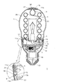
電球形蛍光ランプ1は、図1に示すように、発光管3と、補助電球(本発明における「発光体」に相当する。)4と、発光管3及び補助電球4を保持する保持部材5と、保持部材5における発光管3及び補助電球4が位置する側と反対側に装着され且つ発光管3及び補助電球4を発光(点灯)させるための点灯ユニット7と、点灯ユニット7を内部に収納するように保持部材5に取着されているケース9と、発光管3及び補助電球4を内部に収納するようにその開口部分が保持部材5やケース9に固着されているグローブ11とを備える。
(1)発光管について
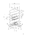
図2は、本実施の形態に係る発光管の概略図である。なお、発光管3の内部の様子が分かるように、ガラス管13の一部を切り欠いている。
(1)発光管について
図2は、本実施の形態に係る発光管の概略図である。なお、発光管3の内部の様子が分かるように、ガラス管13の一部を切り欠いている。
発光管3は、ガラス管13を湾曲させてなる発光管本体31と、この発光管本体31の端部3a,3bに封着された電極33とを備える。なお、図2では、発光管3の一方の端部3aの電極33だけが現れているが、発光管3の他方の端部3bにも同構成の電極が封着されている。また、発光管本体31の端部、ガラス管13の端部は、発光管3の端部3a,3bでもあり、これら端部の符号に「3a」、「3b」を用いる。
発光管本体31は、仮想の旋回軸A上にガラス管13の中央部(この中央部を「発光管の先端部」ともいい、符号「3c」を用いる。)が位置し、当該中央部の両側部分が前記旋回軸Aの廻りを一定の旋回半径でそれぞれ一定方向(図2では「B」である。)に旋回する2重螺旋形状をしている。
つまり、発光管本体31は、一定の旋回半径で且つ当該旋回軸Aに沿って一定方向(例えば、図2において下方である。)に移動しながら、旋回軸Aの廻りを旋回している第1の旋回部31a及び第2の旋回部31bと、2つの旋回部31a,31bと連続する連続部31cとを有する。なお、発光管本体は、ガラス管1本で構成しても良いし、複数本で構成しても良い。
第1の旋回部31aと第2の旋回部31bは、互いに同一の旋回ピッチ(旋回軸Aの廻りを1周する間の旋回軸A上の移動量であり、図中の「P1」である。)で旋回し、また、第1の旋回部31aを構成しているガラス管13の軸心と、第2の旋回部31bを構成しているガラス管13の軸心との間の距離(図中の「P2」である。)は、発光管本体31の端部3a,3b近傍(例えば、発光管3における保持部材5内に挿入される部分である。)を除いて、略一定である。なお、図2におけるP1,P2の寸法線は、各旋回部31a,31bにおけるガラス管13の中心(軸心)を通る。なお、旋回ピッチは、一定でも良いし、変化しても良いし、さらには、一定の規則性で変化しても良い。
旋回軸Aの周りを旋回する旋回数は、ランプの仕様(定格電力等)により決定され、また、発光管本体31の端部3a,3b近傍のガラス管13は、旋回軸Aの延伸する方向に隣合うガラス管13との隙間が広くなるように旋回軸Aの廻りを旋回している。
この発光管本体31(ガラス管13)の内面には蛍光体層35が形成されている。この蛍光体層35は、1又は複数種類の蛍光体、例えば希土類の蛍光体を含んでいる。また、発光管本体31の内部には、発光物質である水銀や、緩衝ガスとして希ガス等が封入されている。
電極33は、図2に示すように、フィラメントコイル41と、このフィラメントコイル41を架持する(架設した状態に保持する)一対のリード線43,45とからなり、一対のリード線43,45がビーズガラス47により保持(ビーズガラスタイプ)されている。なお、ビーズガラス47は、発光管本体31の外部に位置している場合には、電極33を発光管本体31に封着した後に除去しても良いし、そのまま残存していても良い。当然、発光管本体31内に存在していても良い。
フィラメントコイル41は、例えばタングステン製の素線を複次巻き(コイル状)にしたものからなり、電子放射物質が充填されている。また、リード線43,45は、複数の金属線を接続することにより一本化したものでも良いし、1本の金属線をそのまま使用したものでも良い。
電極33は、一対のリード線43,45のうち、ビーズガラス47とフィラメントコイル41との間に位置している部分で、発光管本体31の端部3aがピンチ封止(圧潰封止)されることにより、発光管本体31に封着されている。
発光管本体31の端部3aには、電極33が封着された後の発光管本体31内を真空にしたり、水銀、緩衝ガス等を封入したりする際に使用する細管49が電極33と共に封着されている。この細管49は、発光管本体31の内部を排気し、さらに水銀、緩衝ガスを封入した後に、例えば、発光管本体31の外部に位置する部分がチップオフ方式で封止される。これにより、発光管本体31の内部に放電空間48が形成される。
(2)補助電球
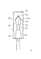
図3は、本実施の形態に係る補助電球の概略図である。
(2)補助電球
図3は、本実施の形態に係る補助電球の概略図である。
補助電球4は、電球形蛍光ランプ1を点灯させた際の始動時(所謂、「点灯始動時」である。)にあわせて点灯するものであって、例えば、フィラメントコイル51を有するフィラメント電球であり、発光管3の光束立上がり特性よりも良い特性を有する。
補助電球4は、図3に示すように、ガラスバルブ50と、フィラメントコイル51を保持するステム52とからなり、当該ステム52がガラスバルブ50に封着されてなる。
ここでは、ガラスバルブ50は円筒状(横断面形状が円形状である。)をしている。また、図3において、ガラスバルブ50は透明であるため、内部にあるステム52等の部材は実線で表している。
ステム52は、フィラメントコイル51と、当該フィラメントコイル51に給電し且つ前記フィラメントコイル51を保持する一対のリード線53,54と、ステム52がガラスバルブ50にステム封止された後に当該ガラスバルブ50内を排気等するための細管55と、当該細管55と前記一対のリード線53,54とを保持するフレアー56とを備える。
フィラメントコイル51は、例えば、タングステン材料製の素線を複次巻き(コイル状)にしたものが使用され、図3に示すように、その中央部51c(コイル軸方向の中央である。)で屈曲し、全体として、ガラスバルブ50の開口側に拡がる逆「V」字状をし、その端部51a,51bが一対のリード線53,54に取着されている。
なお、本実施の形態では、フィラメントコイル52の中央部51cを係止して、フィラメントコイル51を吊設する吊設具57が、細管55におけるガラスバルブ50内に位置する端部に設けられている。
なお、ステム52がガラスバルブ50に封止された後に、細管55を介して、ガラスバルブ50内が排気され、不活性ガス(例えば、アルゴンガス)がガラスバルブ50内に封入されている。また、リード線53,54は、複数の金属線を接続することにより一本化したものでも良いし、1本の金属線をそのまま使用したものでも良い。
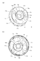
(3)保持部材
図4は、本実施の形態に係る保持部材の斜視図であり、(a)は発光管の大部分が位置する側から見た図であり、(b)は基板が位置する側から見た図である。
(3)保持部材
図4は、本実施の形態に係る保持部材の斜視図であり、(a)は発光管の大部分が位置する側から見た図であり、(b)は基板が位置する側から見た図である。
保持部材5は、図1及び図4に示すように、例えば、周壁15と、その一端を塞ぐ端壁17とを備え、前記一端が塞がった筒状をしている。
端壁17には、図4に示すように、発光管3の端部3a,3bを保持部材5の内部へと受け入れるための受入口17a,17bと、発光管3の端部3a,3bを受入口17a,17bへと案内する案内溝17c,17dと、受入口17a,17bから受け入れられた発光管3の端部3a,3bを被覆する被覆部17e,17fと、補助電球4を保持する電球保持部18とが形成されている。
電球保持部18は、補助電球4の封止部側に位置する外周部分に当接する外周当接部18aと、補助電球4の封止部側に位置する端部(補助電球4の底部)に当接する底部当接部18bとを有する。
外周当接部18aは、端壁17の中央部から口金側に凹入する凹入部分と、当該凹入部分の周縁から発光管3の先端部3c側へと凸出する凸出部分とから構成されている。
つまり、外周当接部18aにおける発光管3の先端部3c側に位置する端部が、端壁17から発光管3の先端部3c側に張り出している(この張り出し部分が上記の凸出部分である。)。
なお、本実施の形態では、凹入部分及び凸出部分の内周面形状は、補助電球4のガラスバルブ50に対応しており(ガラスバルブ50の横断面における外周形状に対応している。)、平面視(発光管3の旋回軸Aが延伸する方向から見た場合である。)において円形状をしている。
底部当接部18b(及び外周当接部18a)には、補助電球4の一対のリード線53,54を保持部材5の内部(端壁17の裏面側)へと導くための貫通孔18c,18dが形成されており、また底部当接部18bには、補助電球4の細管55が保持部材5と緩衝しないようにするための貫通孔18eが形成されている。
本実施の形態では、図4の(b)に示すように、貫通孔18eの周縁から基板21側へと凸出する凸出部を有している。また、底部当接部18bに設けられている貫通孔18d,18cは、端壁17に形成されている一対の受入口17a,17bの間に位置している。
図5は、発光管及び補助電球の保持状態を説明するための保持部材の裏側から見た図であり、(a)は発光管と補助電球とを固着する前の状態を示し、(b)は発光管と補助電球とを固着剤で固着した状態を示す。
発光管3の保持は、図1及び図5の(b)に示すように、保持部材5の受入口17a,17bから発光管3の端部3a,3bを内部に受け入れた状態(図5の(a)である。)で、発光管3の端部3a,3bが固着剤(本発明の「第1の固着剤」に相当し、例えばシリコーン樹脂である。)19a,19bにより保持部材5の内面(端壁17の裏面や周壁15の内面)に固着されることで行われる。
また、補助電球4の保持は、電球保持部18に補助電球4の端部(ステム封止部側の端部)が挿入された状態(図5の(a)である。)で、補助電球4の下端部が固着剤(本発明の「第2の固着剤」に相当し、例えばシリコーン樹脂である。)20a,20bにより保持部材5の内面(端壁17の裏面)や電球保持部18の内面(外周当接部18a及び/又は底部当接部18b)に固着されることで行われる。
この際、電球保持部18に補助電球4の端部が挿入された状態では、補助電球4の外周と底部とが電球保持部18と当接し、安定した状態で、補助電球4の固定が行われる。
また、貫通孔18c,18dは、電球保持部18の中心(この中心は、保持部材5の中心でもある。)を基準とする周方向に沿って形成され、その一端が、受入口17a,17bの端縁と略一致し、他端が、受入口17a,17bから挿入されている発光管3の端と略一致している。つまり、貫通孔18c,18dは、保持部材5に挿入された発光管3の端部3a,3bに対応して形成されている。
発光管3と補助電球4との固着に際しては、まず、貫通孔18c,18dを利用して、電球保持部18内へと固着剤20a,20bを流入して、補助電球4の下部側の外周面と電球保持部18の内周面との隙間に固着剤20a,20bを充填する。その後、発光管3の端部3a,3bを覆うように固着剤19a,19bが流入される。
発光管3と補助電球4とが固着剤19a,20a,19b,20bにより固着された状態では、結果的に、補助電球4を固着している固着剤20a,20bと、発光管3を固着している固着剤19a,19bとがつながった1つの塊が各受入口17a,17bに対応して形成される(一体化されており、この一体となったものを符号「21a」,「21b」で示す。)。
これにより、固着剤21a,21bは、発光管3の端部3a,3bと補助電球4との両方と接触することとなり、補助電球4で発生した熱を発光管3へと伝え易くなり、点灯始動時の発光管3の温度上昇を早めることができる。
また、発光管3と補助電球4を同時に固着することができ、これにより作業性の改善が図れ、さらに固着剤21a,21bの使用量の低減も可能となる。
(4)点灯ユニット
図6は、本実施の形態に係る点灯ユニットの構成図である。
(4)点灯ユニット
図6は、本実施の形態に係る点灯ユニットの構成図である。
点灯ユニット7は、主に整流器61、平滑器62、スイッチング+安定器63、電球点灯制御器64等から構成されている。なお、発光管3を点灯させるスイッチング+安定器には、例えばシリーズインバータ方式の回路が用いられる。以下、点灯ユニット7の一例について説明する。
整流器61は、商用低周波交流を整流して直流に変換するもので、例えば、4つのダイオードブリッジ素子等から構成されている。平滑器62は、整流器61から出力された直流電流を平滑化するもので、例えば、電解コンデンサC1,C2などから構成されている(所謂、倍電圧整流器である。)。なお、点灯ユニット7は、口金23を介して商用低周波交流電源に接続されることになる。
整流器61と平滑器62との間には、平滑器62から整流器61へと電流の逆流を防止するためのダイオードD1,D2が接続されている。
スイッチング+安定器63は、平滑器62からの出力を利用して、発光管3に高周波電力を供給したり、点灯中の発光管3に発生する電流変化を安定させたりする。具体的には、スイッチング作用は、例えば、一対のスイッチング素子(例えば、トランジスタ等)や結合コンデンサ等により、また、安定作用は、チョークコイルや共振用コンデンサ等により達成される。
本実施の形態では、ICチップを利用しており、例えば、上記の一対のスイッチング素子等が集積されている。安定器用のチョークコイルや共振コンデンサは、発光管3を点灯(絶縁破壊)させるための共振回路も構成する。
補助電球4は、整流器61の出力側に接続された配線(給電路)L1,L2を介して点灯され、点灯・消灯の制御は電球点灯制御器64により行われる。電球点灯制御器64は、配線L3,L4を介して、平滑器62の出力側に接続されており、所定条件(例えば、点灯始動後60(sec)経過後である。)になると、補助電球4への給電を停止して消灯させる。
整流器61と口金23との間には、温度ヒューズ66が接続されており、例えば、ケース9内の雰囲気温度及び回路部品等が過度に温度上昇したときに、整流器61側への給電が停止するようにしている。過度な温度上昇としては、点灯始動してから所定時間が経過すると本来消灯すべき補助電球4が消灯せずに点灯を続けている場合や、発光管3内の電極33が寿命末期に近づいた場合等がある。
図7は、電球点灯制御器の回路図である。
電球点灯制御器64は、例えば、2つのトランジスタQ1,Q2、抵抗R1、コンデンサC4等を備え、トランジスタQ1のオン・オフ状態で、補助電球4が点灯・消灯される。
つまり、点灯始動すると、補助電球4に接続されているトランジスタQ1がオン状態となり補助電球4が点灯し、補助電球4が点灯して所定時間経過すると、接続ノードN1の分圧が所定値になるとトランジスタQ1(スイッチング素子である。)がオフ状態となり、補助電球4が消灯する。
補助電球4は、その一方のリード線が配線L1に、他方のリード線がトランジスタQ1のドレインに接続されている。トランジスタQ1は、ソースが配線L4(L2)に接続され、ゲートがトランジスタQ2のコレクタに接続されている。
トランジスタQ2のベースは、抵抗R4、ツェナダイオードZ1を介して接続ノードN1に接続され、トランジスタQ2のエミッタが配線L2に接続されている。接続ノードN1は、抵抗R1、接続ノードN3を介して配線L3に接続され、また、コンデンサC4を介して配線L4(L2)に接続されている。
また、トランジスタQ2のコレクタとトランジスタQ1のゲートとの間の接続ノードN2は、配線L3と接続する抵抗R1の入力側の接続ノードN3に抵抗R2を介して、また配線L2に抵抗R3を介して、それぞれ接続されている。なお、抵抗R2,R3は、接続ノードN2の電圧調整用である。
次に電球点灯制御器64の動作について説明する。
まず、電球形蛍光ランプ1の点灯が始動する(電源がオンされる)と、補助電球4には配線L1から給電されて点灯し、これにあわせてコンデンサC4に徐々に電荷が蓄積される。なお、この際、トランジスタQ1はオン状態である。
始動開始後、コンデンサC4の充電が完了して接続ノードN1の電圧が所定値になると、ツェナダイオードZ1が絶縁破壊して、トランジスタQ2がオン状態となる。これにより、トランジスタQ1がオフ状態となり、補助電球4が消灯する。
電球点灯制御器64は、上述したように、コンデンサC4の充電時間を利用したものであり、点灯始動から補助電球4の消灯までの時間は、コンデンサC4の容量や抵抗R1の抵抗値により設定できる。
図8は、点灯ユニットの斜視図である。
基板22には、同図に示すように、その中央部にチョークコイルCHが実装されており、当該チョークコイルCHに対して所定の間隔(例えば、4(mm)程度)を置いてICチップICが実装されている。ICチップICは、複数のリードICa,ICbを有し、これらリードICa,ICbが基板22を貫通して、その裏面側(基板22におけるチョークコイルCHが実装されている側を表面としている。)で半田等により固着されている。また、2つの電解コンデンサC1,C2が、その本体部C1a,C2aがチョークコイルCHの上方に位置するように、リード線を介して基板22に実装されている。
また、ICチップICとチョークコイルCHとの間には、温度ヒューズ66が配されており、当該温度ヒューズ66がICチップICから延出している複数のリード(図8には現れていない。)に接触している。これは、例えば、補助電球4が所定時間経過後も点灯している場合に、補助電球4側の熱を前記リードから温度ヒューズ66に伝えることができる。
また、電極寿命末期に電極33が過度に温度上昇すると、チョークコイルCHが飽和状態となり温度上昇する。上記の温度ヒューズ66は、チョークコイルCHの近傍に配されているので、この熱(温度)も検知する。この温度が所定以上になると、温度ヒューズ66が溶断して、整流器61への電力供給が停止する。
基板22の保持部材5への取着は、図1の一部拡大図や図4の(b)で示すように、例えば、保持部材5の周壁15の開口縁から、保持部材5の軸心(図1における上下方向であり、旋回軸Aの延伸方向と一致する。)と平行な方向に延出する複数の突出部15bが基板22に当接した状態で、同じく周壁15の開口縁から保持部材5の軸心と平行な方向に延出する複数の係止腕15aが基板22の周縁に係合することで行われる。
なお、係止腕15aは、ここでは、周壁15の周方向に等間隔をおいて、例えば4個設けられ、突出部15bは、周壁15の周方向に等間隔をおいて、例えば2個設けられている。
(5)ケース
ケース9は、図1に示すように、例えばコーン状をしており、大径筒部9aと、当該大径筒部9aよりも径の小さい小径筒部9bと、大径筒部9aと小径筒部9bとを連結する傾斜筒部9cとを備える。ケース9の小径筒部9bには、ねじ込み型の口金23、例えば、E26型が被着されている。
(5)ケース
ケース9は、図1に示すように、例えばコーン状をしており、大径筒部9aと、当該大径筒部9aよりも径の小さい小径筒部9bと、大径筒部9aと小径筒部9bとを連結する傾斜筒部9cとを備える。ケース9の小径筒部9bには、ねじ込み型の口金23、例えば、E26型が被着されている。
ケース9と保持部材5との取着は、図1の拡大図に示すように、保持部材5の周壁15の外面に形成された係合突部15cが、ケース9の内周面に形成された係止凹部9dに係合することで行われる。
係合突部15cは、保持部材5の周縁を全周に亘って鍔状に形成されているが、その周縁を周方向に等間隔を置いて複数個形成するようにしても良い。また、係止凹部9dは、ケース9その周方向に等間隔を置いて複数個、例えば4個形成されている。さらに、係合突部や係止凹部は互いに係合すれば良く、ケース或いは保持部材のどちらに設けられても良い。
(6)グローブ
グローブ11は、ここでは、例えばA形のものが利用され、グローブ11の開口側の端部11aが、ケース9と保持部材5との間の隙間に挿入された状態で、当該隙間に充填されている固着剤25、例えば、シリコーン樹脂によりケース9及び保持部材5に固着されている。
(6)グローブ
グローブ11は、ここでは、例えばA形のものが利用され、グローブ11の開口側の端部11aが、ケース9と保持部材5との間の隙間に挿入された状態で、当該隙間に充填されている固着剤25、例えば、シリコーン樹脂によりケース9及び保持部材5に固着されている。
グローブ11の底(図1では上端部であり、口金23から遠く離れた側の端部である。)11bには、発光管3の先端部3cに形成された凸部3d(この凸部は点灯時に最冷点箇所となる部分である。)と熱的に連結する熱連結部材27が設けられている。この熱連結部材27は、発光管3が点灯した際に発光管3の熱をグローブ11に伝えて、発光管3の温度を下げるためのものである。
なお、グローブ11の内表面には、例えば炭酸カルシウムを主成分とする拡散膜28が塗布されている。
2.実施例
上記実施の形態に係る発光管の実施例について説明する。
(1)構成
発光管本体31を構成するガラス管13は、鉛フリーガラス材料で構成され、図2に示すように、その内径D1が5.9(mm)、外径D2が7.5(mm)であり、ガラス管13の中心軸が旋回軸Aの周りを旋回する旋回半径が約12.8(mm)である。これにより、外周径D3が約33(mm)の2重螺旋形状の発光管本体31が得られる。
2.実施例
上記実施の形態に係る発光管の実施例について説明する。
(1)構成
発光管本体31を構成するガラス管13は、鉛フリーガラス材料で構成され、図2に示すように、その内径D1が5.9(mm)、外径D2が7.5(mm)であり、ガラス管13の中心軸が旋回軸Aの周りを旋回する旋回半径が約12.8(mm)である。これにより、外周径D3が約33(mm)の2重螺旋形状の発光管本体31が得られる。
旋回軸Aを旋回する第1及び第2の旋回部31a,31bの旋回数の合計は、5回である。また、第1の旋回部31aと第2の旋回部31bの旋回ピッチP1は18(mm)であり、第1の旋回部31aの軸心と、第2の旋回部31bの軸心との間の距離P2は、9(mm)である。つまり、旋回軸Aの延伸方向に隣接し合うガラス管13間の隙間(隣接するガラス管13の外周同士の間隔で最も狭い部分の隙間)は、1.5(mm)である。
発光管本体31を構成するガラス管13の内面に形成される蛍光体層35には、例えば、赤(Y2O3:Eu)、緑(LaPO4:Ce、Tb)及び青(BaMg2Al16O27:Eu、Mn)発光の3種類の希土類系の蛍光体を用いている。
発光管本体31に封入される水銀は、1(mg)であり、希ガスには、アルゴン、クリプトンの混合ガスが用いられ、550(Pa)で封入されている。放電空間48内における両フィラメントコイル41の中心軸間距離(所謂、電極間距離である。)は、400(mm)である。
発光管3の端部3a,3bの保持部材5の内部への挿入量は、図5の(a)に示すように、1/4周分である。つまり、受入口17a,17bの端縁から、保持部材5の中心Oを基準にして、周方向に沿って90度分回転した位置までであり、電球保持部18の貫通孔18c,18dも、保持部材5内の発光管3の端部3a,3bに対応して設けられている。
そして、発光管3の各端部3a,3bと補助電球4とを固着する固着剤20a,20bが、図5の(b)に示すように、受入口17a,17bの端縁から、保持部材5の中心Oを基準にして、発光管3の端部3a,3bが挿入されている方向と反対方向に、45度分戻った位置から、発光管3の端部3a,3bの先端までの領域に設けられている。
なお、図5の(b)において、固着剤21a,21bが設けられている領域を、ハッチング部分で示している。また、発光管3の端部3aを固着している固着剤19aと、端部3bを固着している固着剤19bとはつながっていない。
当該電球形蛍光ランプは、発光管3への入力(所謂、ランプ入力である。)が10(W)で、定格時の発光光束は一般白熱電球60Wと同じ810(lm)である。また、補助電球4への入力が20(W)で、このときの定格時の発光光束は200(lm)である。
点灯始動から、発光管及び補助電球が発光し、補助電球は始動後約1分間経過すると消灯し、その後発光管3だけが点灯維持される。
(2)光束比較試験結果
上記実施例で説明した本発明に係る電球形蛍光ランプ(以下、「発明品」という。)と、補助電球4を有さずに発光管のみを有する電球形蛍光ランプ(上記発明品と区別するために、以下、「従来品」という。)とを用いて、点灯始動から5分経過するまでの光束立上がり特性の比較試験を行った。
(2)光束比較試験結果
上記実施例で説明した本発明に係る電球形蛍光ランプ(以下、「発明品」という。)と、補助電球4を有さずに発光管のみを有する電球形蛍光ランプ(上記発明品と区別するために、以下、「従来品」という。)とを用いて、点灯始動から5分経過するまでの光束立上がり特性の比較試験を行った。
なお、試験を行った環境条件は、周辺温度が5(℃)、であり、この条件下で、電球形蛍光ランプを口金上点灯して行なった。
図9は、光束立上がり特性の比較結果を示す図である。
図中の「A」は発明品の立上がり特性を示し、図中の「B」は発光体(補助電球)を有しない電球形蛍光ランプの立上がり特性を示す。同図における縦軸は定常点灯時の光束に対する比率であり、100(%)は、定常点灯時の光束(本実施例では810(lm)である。)を指す。また、同図における横軸は、点灯始動からの経過時間である。なお、発明品とは、発光管3の端部3a,3bと補助電球4の下端部とを固着剤21a(19a,20a),21b(19b,20b)で一体に固着したものである。
同図に示すように、補助電球を有しない電球形蛍光ランプでは、時間の経過とともに、光束が増加し、点灯始動から約300(Sec)後に定常点灯時の光束の約80(%)に達している。これに対し、発明品は、点灯始動から80(%)に達するまでの時間が240(Sec)である。つまり、点灯始動から80(%)に達するまでの時間が本発明品の方が短く、補助電球を有しない電球形蛍光ランプに対して、約2割程度光束立上がり特性が向上している。
この光束立上がり特性の向上の原因は、補助電球を有し、発光管を構成するガラス管がその補助電球の廻りを旋回する構成としているからである。つまり、発光管の温度が補助電球の発光時の熱により加熱され、発光管内の温度が上昇し、結果的に水銀蒸気圧が上昇して、光束立上がり特性が改善したものと考えられる。
そして、発明品における光束立上がりは、発光管と保持部材とを固着する固着剤19a,19bと、補助電球と保持部材とを固着する固着剤20a,20bとがつながっていない電球形蛍光ランプに比べて、5%程度、点灯始動直後からほぼ300(Sec)経過するまでの時間で、向上していることを実験にて確認している。
また、発明品では、点灯始動直後から、定常点灯時の光束の30(%)に達している。これは、点灯始動に合わせて点灯した補助電球4の光束によるものである。
3.その他
(1)補助電球
本実施の形態では、発光管の発光光束は810(lm)で、補助電球の発光光束は200(lm)である。実施の形態では補助電球の発光光束について説明しなかったが、発光管の発光光束(定常点灯時)に対して、20(%)以上、40(%)以下の範囲の光束を発するのが好ましい。
3.その他
(1)補助電球
本実施の形態では、発光管の発光光束は810(lm)で、補助電球の発光光束は200(lm)である。実施の形態では補助電球の発光光束について説明しなかったが、発光管の発光光束(定常点灯時)に対して、20(%)以上、40(%)以下の範囲の光束を発するのが好ましい。
この理由は、発光管の発光光束に対して20(%)未満の場合は、点灯直後の光束が低く、輝度不足となるからである。一方、40(%)より大きいと、補助電球を消灯させた前後の輝度の差が大きくなりすぎ、且つ補助電球の温度が高くなり、保持部材の材質を高価な高耐熱樹脂を使わなければならなくなるからである。
(2)旋回部について
実施の形態では、旋回軸方向に隣り合う第1の旋回部31aのガラス管と、第2の旋回部のガラス管との隙間は、1.5(mm)であったが、この隙間は、0.5(mm)以上、5(mm)以下が好ましい。
(2)旋回部について
実施の形態では、旋回軸方向に隣り合う第1の旋回部31aのガラス管と、第2の旋回部のガラス管との隙間は、1.5(mm)であったが、この隙間は、0.5(mm)以上、5(mm)以下が好ましい。
この理由は、この隙間が0.5(mm)未満の場合は、補助電球から発せられた光束が、ランプの光束向上の寄与しなくなり、逆に、5(mm)より大の場合は、隙間から補助電球から光が照射されて、輝度ムラが大きくなり、且つランプ自体が大きくなるからである。
<変形例>
以上、本発明を実施の形態に基づいて説明したが、本発明の内容が、上記の実施の形態に示された具体例に限定されないことは勿論であり、例えば、以下のような変形例を実施することができる。
1.ランプ
実施の形態では、所謂、A形の電球形蛍光ランプについて説明したが、他のタイプの電球形蛍光ランプであっても良い。他の例としては、グローブの形状が、例えばG形をしたもの等がある。
<変形例>
以上、本発明を実施の形態に基づいて説明したが、本発明の内容が、上記の実施の形態に示された具体例に限定されないことは勿論であり、例えば、以下のような変形例を実施することができる。
1.ランプ
実施の形態では、所謂、A形の電球形蛍光ランプについて説明したが、他のタイプの電球形蛍光ランプであっても良い。他の例としては、グローブの形状が、例えばG形をしたもの等がある。
また、グローブを備えない、所謂D形の電球形蛍光ランプであっても良い。
図10は、D形の電球形蛍光ランプの縦断面を示す図である。
電球形蛍光ランプ101は、図1に示すように、発光管3と、補助電球4と、発光管3及び補助電球4を保持する保持部材105と、保持部材105における発光管3及び補助電球4が位置する側と反対側に装着され且つ発光管3及び補助電球4を発光(点灯)させるための点灯ユニット7と、点灯ユニット7を内部に収納し且つ保持部材5に取着されているケース109とを備える。
D形の電球形蛍光ランプ101は、実施の形態で説明した電球形蛍光ランプ1との比較において、保持部材105とケース109とが異なる以外、略同じ構成をしている。
保持部材105は、筒状をした周壁105bと、当該周壁105bの一端を塞ぐ端壁105aとを備える有底筒状をしている。端壁105aには、発光管3を内部に受け入れるための受入口や、補助電球4を保持するための電球保持部等が形成されている。周壁105bは、ケース109の開口部分に内挿された状態で、例えば、固着剤111で固着されている。なお、保持部材105とケース109との結合は、固着剤以外の手段、例えば、係合手段、螺合手段等を利用しても良い。
周壁105bには、外周径の異なる、大径部と小径部とがあり、小径部がケース109内に挿入される。なお、周壁は、例えば、外周径が同一の筒状をしていても良いし、さらには、横断面形状が多角形状をしていても良い。
2.発光管
実施の形態での発光管の旋回部は、当該旋回部に相当する部分のガラス管が旋回軸の廻りを略同一の旋回半径で旋回する形状をしていたが、発光管は他の螺旋形状をしていても良い。他の形状としては、当該旋回部に相当する部分のガラス管が旋回半径を変えながら旋回する形状をしていても良い。なお、旋回半径の変化は、徐々に大きくなったり、大小を繰り返したりしても良い。
2.発光管
実施の形態での発光管の旋回部は、当該旋回部に相当する部分のガラス管が旋回軸の廻りを略同一の旋回半径で旋回する形状をしていたが、発光管は他の螺旋形状をしていても良い。他の形状としては、当該旋回部に相当する部分のガラス管が旋回半径を変えながら旋回する形状をしていても良い。なお、旋回半径の変化は、徐々に大きくなったり、大小を繰り返したりしても良い。
また、実施の形態の発光管は、2つの旋回部を有していたが、旋回部は1つであっても良い。このような例としては、旋回部に相当する部分のガラス管が旋回軸の廻りを、ガラス管の一端が他端から離れるように、一定方向に旋回して旋回部を構成しても良い(所謂、一重螺旋形状である。)。この場合も、補助電球を前記1つの旋回部内に形成されている空間に配すれば実施できる。
さらに、発光管は、例えば、U字形状をしたガラス管を複数本(例えば、3本)ブリッジ結合して構成した、所謂、3Uタイプであっても良い。
3.補助電球
実施の形態では、発光体(補助電球)として、シリカ電球を用いたが、他の発光体を用いても良い。他の発光体としては、LED素子、シリカ電球以外の電球(例えばクリプトン電球)等がある。なお、点灯始動直後の発光管の温度を上昇させて、光束立上がり特性を改善するには、発光体が発光時に発光管の温度以上になる必要がある。
4.補助アマルガム
実施の形態における発光管は、補助アマルガムを有しないタイプであったが、補助アマルガムを有するタイプであっても良い。
3.補助電球
実施の形態では、発光体(補助電球)として、シリカ電球を用いたが、他の発光体を用いても良い。他の発光体としては、LED素子、シリカ電球以外の電球(例えばクリプトン電球)等がある。なお、点灯始動直後の発光管の温度を上昇させて、光束立上がり特性を改善するには、発光体が発光時に発光管の温度以上になる必要がある。
4.補助アマルガム
実施の形態における発光管は、補助アマルガムを有しないタイプであったが、補助アマルガムを有するタイプであっても良い。
図11は、補助アマルガムを有する発光管の端部を示す図であり、ガラス管の内部が分かるように、ガラス管の一部を切り欠いている。
本例においても、フィラメントコイル121は、一対のリード線123,125に架設されており、このリード線123,125の中央部分でガラス管127の端部に細管129と共に封着されている。
一対のリード線123,125には、ガラス管127内に位置する部分に補助アマルガム131が設けられている。この補助アマルガム131は、例えば、インジウムメッキのステンレスメッシュの切片が用いられている。なお、補助アマルガムは、他の金属、例えば、ガリウム、インジウム、鉛等の金属材料であっても良い。
図9のcは、補助アマルガムを有する発光管を用いた電球形蛍光ランプを点灯させた際の光束立上がり特性を示している。
図9のaとcとの違いは、補助アマルガムの有無である。両者を比較すると、点灯始動直後は、補助電球により、光束が急速に立上っている。しかし、その後始動してから60秒が経過するまでは、光束増加の勾配が補助アマルガムを有する場合のcの方が高いことが分かる。これは、補助アマルガムの効果と補助電球による熱効果との相乗効果により、補助電球のみを用いた場合(aである。)よりも勾配が大きくなったと考えられる。
5.保持部材
保持部材は、発光管を保持する機能、補助電球を保持する機能、場合によっては、基板を取着する機能、ケースやグローブと固着できる機能等を有しておれば良く、その構成は、実施の形態で説明した保持部材に限定するものではない。
5.保持部材
保持部材は、発光管を保持する機能、補助電球を保持する機能、場合によっては、基板を取着する機能、ケースやグローブと固着できる機能等を有しておれば良く、その構成は、実施の形態で説明した保持部材に限定するものではない。
図12は、変形例に係る保持部材の概略斜視図であり、(a)は発光管本体の大部分が位置する側から見た図であり、(b)は基板が位置する側から見た図である。なお、この保持部材151は、上記で説明した、グローブを備えないD形の電球形蛍光ランプ用である。
図13は、発光管と補助電球とを固着剤で固着した状態を示す。
保持部材151は、図12に示すように、例えば、周壁153と端壁155とを備えた有底筒状をしている。端壁155には、実施の形態で説明した保持部材5と同様に、受入口155a,155b、案内溝155c,155d、被覆部155e,155f、電球保持部157等が形成されている。
電球保持部157は、実施の形態と同様に、外周当接部157aと底部当接部157bとを有する。
外周当接部157aは、端壁155の中央部から口金側に凹入する凹入部分から構成されている。つまり、外周当接部157aにおける発光管3の先端部3c側に位置する端面が、実施の形態と異なり、端壁155と略面一となっている。
底部当接部157b及び外周当接部157aには、補助電球の一対のリード線を保持部材151の内部(端壁155の裏面側)へと導くための切欠き部157c,157dが形成され、また底部当接部157bには、補助電球の細管が保持部材151と緩衝するのを防止するための貫通孔157eが設けられている。
本例においても、切欠き部157c,157dは、端壁155に形成されている一対の受入口155a,155bの間に位置している。なお、本例においては、端壁155の裏面には、発光管の端部を位置決めするための保持片155g,155hが形成されている。
また、図13にも示すように、切欠き部157c,157dは、保持部材151に挿入された発光管3の端部3a,3bに対応し、電球保持部157の中心(この中心は、保持部材151の中心でもある。)Oを基準とする周方向に沿って形成され、その一端が、受入口155a,155bの端縁と略一致し、他端が、受入口155a,155bから挿入されている発光管3の端と略一致している。
図13では、固着剤は、ハッチング部分に設けられている。そして、発光管3と補助電球4とが固着剤161a,161bにより固着された状態では、結果的に、補助電球4を固着している固着剤162a,162bと、発光管3とを固着している固着剤161a,161bとがつながった1つの島状の塊として、各切欠き部157c,157dに対応して形成される(一体化されており、一体となったものを符号「163a」,「163b」で示す。)。
なお、本変形例では、保持部材151の端壁155の裏面に形成されている保持片155g,155hは、固着剤163a,163bの流動を規制するダム機能も有している。
6.照明装置
実施の形態では、特に、放電ランプについて説明したが、本発明は、上記放電ランプを利用した照明装置にも適用できる。
6.照明装置
実施の形態では、特に、放電ランプについて説明したが、本発明は、上記放電ランプを利用した照明装置にも適用できる。
図14は、本発明に係る照明装置の概略図である。
照明装置200は、例えば、天井202に装着されて、使用される。
この照明装置200は、図14に示すように、放電ランプ(例えば、電球形蛍光ランプ1である。)と、電球形蛍光ランプ1を装着し点灯させる点灯器具201とを備える。
点灯器具201は、例えば、天井202に取着される器具本体204と、器具本体204に装着された電球形蛍光ランプ1を覆うカバー206とを備える。
器具本体204には、電球形蛍光ランプ1の口金23が取着(螺着)されるソケット208を備え、このソケット208を介して電球形蛍光ランプ1に給電される。
なお、ここでの照明器具は、一例であり、例えば、閉塞型のカバーを有さずに、開口型のカバーを有するものであっても良いし、放電ランプが横を向くような姿勢(ランプの中心軸が水平となるような姿勢)で点灯させるような照明器具でも良い。
さらに、ここでは、1つの放電ランプを点灯させているが、複数、例えば、3個の放電ランプを点灯させるようなものでも良い。
本発明に係る低圧水銀放電ランプ及び照明装置は、点灯始動時の光束立上がり特性を改善するのに利用できる。
Claims (5)
- 放電発光する発光管と、
前記発光管におけるランプ始動時の光束立上がり特性よりも良い特性を有する発光体と、前記発光管と前記発光体とを固着して保持する保持部材とを備え、
前記発光管と前記保持部材とを固着している第1の固着剤が、前記発光体と前記保持部材とを固着している第2の固着剤とつながっている
ことを特徴とする放電ランプ。 - 前記発光管は、仮想軸廻りに旋回した形状の旋回部を有し、
前記発光体は、前記旋回部に囲繞されている
ことを特徴とする請求項1に記載の放電ランプ。 - 前記発光体は、定常点灯時に発光管から発せられる光束に対して、20%以上、40%以下の範囲内の光束を、点灯始動時に発する
ことを特徴とする請求項1に記載の放電ランプ。 - 前記発光体は、フィラメントコイルを有する電球である
ことを特徴する請求項1に記載の放電ランプ。 - 放電ランプと、前記放電ランプを装着して点灯させる照明器具とを備える照明装置において、
前記放電ランプは、請求項1に記載の放電ランプである
ことを特徴とする照明装置。
Applications Claiming Priority (2)
| Application Number | Priority Date | Filing Date | Title |
|---|---|---|---|
| JP2008003039A JP4709859B2 (ja) | 2008-01-10 | 2008-01-10 | 放電ランプ及び照明装置 |
| JP2008-003039 | 2008-01-10 |
Publications (1)
| Publication Number | Publication Date |
|---|---|
| WO2009087736A1 true WO2009087736A1 (ja) | 2009-07-16 |
Family
ID=40852861
Family Applications (1)
| Application Number | Title | Priority Date | Filing Date |
|---|---|---|---|
| PCT/JP2008/003969 WO2009087736A1 (ja) | 2008-01-10 | 2008-12-25 | 放電ランプ及び照明装置 |
Country Status (2)
| Country | Link |
|---|---|
| JP (1) | JP4709859B2 (ja) |
| WO (1) | WO2009087736A1 (ja) |
Families Citing this family (4)
| Publication number | Priority date | Publication date | Assignee | Title |
|---|---|---|---|---|
| CN102612190A (zh) | 2011-01-22 | 2012-07-25 | 通用电气公司 | 混合灯电源电路 |
| US8845133B2 (en) * | 2011-07-27 | 2014-09-30 | General Electric Company | Thermal barrier and parts fixing in compact fluorescent lamps |
| US20130082596A1 (en) * | 2011-09-29 | 2013-04-04 | General Electric Company | Light detector to control a hybrid lamp |
| KR20210034339A (ko) * | 2019-09-20 | 2021-03-30 | 주식회사 엘지화학 | 자성체가 형성된 분리막을 포함하는 전지셀 및 이를 이용한 내부 단락에 따른 전지셀의 안전성 평가방법 |
Citations (5)
| Publication number | Priority date | Publication date | Assignee | Title |
|---|---|---|---|---|
| JPS5763764A (en) * | 1980-10-02 | 1982-04-17 | Matsushita Electric Ind Co Ltd | Single base type fluorescent lamp device |
| JP2000164174A (ja) * | 1998-11-24 | 2000-06-16 | Matsushita Electronics Industry Corp | 低圧水銀蒸気放電ランプ |
| JP2003520387A (ja) * | 1998-05-06 | 2003-07-02 | ジーエル ディスプレイズ インコーポレイテッド | 冷陰極螢光灯(ランプ)およびディスプレイ |
| JP2004103589A (ja) * | 2002-09-12 | 2004-04-02 | Sukusuun Chan | 空気浄化機能を持つランプ構造物 |
| EP1883099A2 (en) * | 2006-05-19 | 2008-01-30 | Beghelli S.p.A. | Lighting device with a compact structure |
-
2008
- 2008-01-10 JP JP2008003039A patent/JP4709859B2/ja not_active Expired - Fee Related
- 2008-12-25 WO PCT/JP2008/003969 patent/WO2009087736A1/ja active Application Filing
Patent Citations (5)
| Publication number | Priority date | Publication date | Assignee | Title |
|---|---|---|---|---|
| JPS5763764A (en) * | 1980-10-02 | 1982-04-17 | Matsushita Electric Ind Co Ltd | Single base type fluorescent lamp device |
| JP2003520387A (ja) * | 1998-05-06 | 2003-07-02 | ジーエル ディスプレイズ インコーポレイテッド | 冷陰極螢光灯(ランプ)およびディスプレイ |
| JP2000164174A (ja) * | 1998-11-24 | 2000-06-16 | Matsushita Electronics Industry Corp | 低圧水銀蒸気放電ランプ |
| JP2004103589A (ja) * | 2002-09-12 | 2004-04-02 | Sukusuun Chan | 空気浄化機能を持つランプ構造物 |
| EP1883099A2 (en) * | 2006-05-19 | 2008-01-30 | Beghelli S.p.A. | Lighting device with a compact structure |
Also Published As
| Publication number | Publication date |
|---|---|
| JP4709859B2 (ja) | 2011-06-29 |
| JP2009164072A (ja) | 2009-07-23 |
Similar Documents
| Publication | Publication Date | Title |
|---|---|---|
| US7598662B2 (en) | Low-pressure mercury vapor lamp with an adhering unit to improve luminous efficiency | |
| US7178944B2 (en) | Lighting apparatus | |
| KR200449665Y1 (ko) | 엘이디 조명등 | |
| JP4709859B2 (ja) | 放電ランプ及び照明装置 | |
| WO2009087735A1 (ja) | 放電ランプ及び照明装置 | |
| US7411350B2 (en) | Small arc tube, low-pressure mercury lamp, lighting apparatus, mandrel for forming the arc tube, and production method of the arc tube | |
| JP2013004286A (ja) | セラミックメタルハライドランプ照明装置 | |
| US7334916B2 (en) | Illumination device | |
| JP2007273336A (ja) | 蛍光ランプ | |
| US6984926B2 (en) | Compact self-ballasted fluorescent lamp resistant to heat deformation | |
| JP2006310167A (ja) | 蛍光ランプ | |
| WO2007007653A1 (ja) | 電球形蛍光ランプおよび照明装置 | |
| US7298088B2 (en) | Arc tube and low-pressure mercury lamp | |
| JP2005347236A (ja) | 電球形蛍光ランプおよび照明装置 | |
| JP2008226814A (ja) | 電球形蛍光ランプおよび照明器具 | |
| JP2006202668A (ja) | 蛍光ランプ、蛍光ランプ装置及び照明器具 | |
| JP2010251253A (ja) | 放電ランプおよび照明装置 | |
| JP2005209502A (ja) | 蛍光ランプおよび照明器具 | |
| JP2005108677A (ja) | 照明器具 | |
| JP2007048728A (ja) | 電球形蛍光ランプおよび照明装置 | |
| JP2005216773A (ja) | 蛍光ランプ及び照明器具 | |
| WO2010122737A1 (ja) | 発光管、放電ランプ及び照明装置 | |
| JP2006286378A (ja) | 蛍光ランプ装置及び照明装置 | |
| KR960008928B1 (ko) | 2중 구(球)형관 벌브체를 구비한 절전형 형광램프 | |
| JP2010182487A (ja) | 電球形蛍光ランプおよび照明器具 |
Legal Events
| Date | Code | Title | Description |
|---|---|---|---|
| 121 | Ep: the epo has been informed by wipo that ep was designated in this application |
Ref document number: 08869290 Country of ref document: EP Kind code of ref document: A1 |
|
| NENP | Non-entry into the national phase |
Ref country code: DE |
|
| 122 | Ep: pct application non-entry in european phase |
Ref document number: 08869290 Country of ref document: EP Kind code of ref document: A1 |