WO2009081914A1 - レセプタクル部材、および、それが用いられる記録媒体接続用コネクタ - Google Patents
レセプタクル部材、および、それが用いられる記録媒体接続用コネクタ Download PDFInfo
- Publication number
- WO2009081914A1 WO2009081914A1 PCT/JP2008/073354 JP2008073354W WO2009081914A1 WO 2009081914 A1 WO2009081914 A1 WO 2009081914A1 JP 2008073354 W JP2008073354 W JP 2008073354W WO 2009081914 A1 WO2009081914 A1 WO 2009081914A1
- Authority
- WO
- WIPO (PCT)
- Prior art keywords
- contact
- movable piece
- contact terminal
- recording medium
- cable
- Prior art date
Links
Images


Classifications
-
- H—ELECTRICITY
- H01—ELECTRIC ELEMENTS
- H01R—ELECTRICALLY-CONDUCTIVE CONNECTIONS; STRUCTURAL ASSOCIATIONS OF A PLURALITY OF MUTUALLY-INSULATED ELECTRICAL CONNECTING ELEMENTS; COUPLING DEVICES; CURRENT COLLECTORS
- H01R12/00—Structural associations of a plurality of mutually-insulated electrical connecting elements, specially adapted for printed circuits, e.g. printed circuit boards [PCB], flat or ribbon cables, or like generally planar structures, e.g. terminal strips, terminal blocks; Coupling devices specially adapted for printed circuits, flat or ribbon cables, or like generally planar structures; Terminals specially adapted for contact with, or insertion into, printed circuits, flat or ribbon cables, or like generally planar structures
- H01R12/50—Fixed connections
- H01R12/59—Fixed connections for flexible printed circuits, flat or ribbon cables or like structures
- H01R12/592—Fixed connections for flexible printed circuits, flat or ribbon cables or like structures connections to contact elements
-
- H—ELECTRICITY
- H01—ELECTRIC ELEMENTS
- H01R—ELECTRICALLY-CONDUCTIVE CONNECTIONS; STRUCTURAL ASSOCIATIONS OF A PLURALITY OF MUTUALLY-INSULATED ELECTRICAL CONNECTING ELEMENTS; COUPLING DEVICES; CURRENT COLLECTORS
- H01R12/00—Structural associations of a plurality of mutually-insulated electrical connecting elements, specially adapted for printed circuits, e.g. printed circuit boards [PCB], flat or ribbon cables, or like generally planar structures, e.g. terminal strips, terminal blocks; Coupling devices specially adapted for printed circuits, flat or ribbon cables, or like generally planar structures; Terminals specially adapted for contact with, or insertion into, printed circuits, flat or ribbon cables, or like generally planar structures
- H01R12/70—Coupling devices
- H01R12/77—Coupling devices for flexible printed circuits, flat or ribbon cables or like structures
- H01R12/79—Coupling devices for flexible printed circuits, flat or ribbon cables or like structures connecting to rigid printed circuits or like structures
-
- H—ELECTRICITY
- H01—ELECTRIC ELEMENTS
- H01R—ELECTRICALLY-CONDUCTIVE CONNECTIONS; STRUCTURAL ASSOCIATIONS OF A PLURALITY OF MUTUALLY-INSULATED ELECTRICAL CONNECTING ELEMENTS; COUPLING DEVICES; CURRENT COLLECTORS
- H01R13/00—Details of coupling devices of the kinds covered by groups H01R12/70 or H01R24/00 - H01R33/00
- H01R13/46—Bases; Cases
- H01R13/502—Bases; Cases composed of different pieces
- H01R13/506—Bases; Cases composed of different pieces assembled by snap action of the parts
-
- H—ELECTRICITY
- H01—ELECTRIC ELEMENTS
- H01R—ELECTRICALLY-CONDUCTIVE CONNECTIONS; STRUCTURAL ASSOCIATIONS OF A PLURALITY OF MUTUALLY-INSULATED ELECTRICAL CONNECTING ELEMENTS; COUPLING DEVICES; CURRENT COLLECTORS
- H01R31/00—Coupling parts supported only by co-operation with counterpart
- H01R31/06—Intermediate parts for linking two coupling parts, e.g. adapter
Definitions
- the present invention relates to a receptacle member for detachably connecting a recording medium, and a recording medium connecting connector using the same.
- a device in which a hard disk drive (HDD) or a sealed hard disk pack or the like as a recording medium is built in a casing is put into practical use.
- a connection plug also referred to as a hard disk side detachable portion in Patent Document 1.
- the connection plug for example, a connection plug formed in conformity with the SATA standard is widely used.
- connection plug is connected to a base connector which is fixed by soldering on a predetermined substrate.
- a base connector electrically connects a fitting port into which a connection plug is fitted, and a pad of the connection plug and a conductive layer of the substrate.
- JP 2006-278186 A JP 2006-228603 A Utility Model Registration No. 31220666
- the conventional base connector as shown in Patent Document 1 requires a substrate on which the base connector is fixed, and thus has a problem that the manufacturing cost increases.
- the layout of the board may limit the degree of freedom of layout design in the information communication device.
- the present invention provides a receptacle member for detachably connecting a recording medium, and a recording medium connecting connector using the same, and the receptacle member capable of reducing the manufacturing cost of the connector
- Another object of the present invention is to provide a connector for connecting a recording medium in which it is used.
- a receptacle member is formed integrally with a socket portion having a slot portion to which a plug portion of a recording medium is detachably connected, and one end of a cable is attached and detached.
- a cable connection end portion that can be connected, a contact terminal accommodating portion that communicates with the slot portion inside the socket portion and the cable connection end portion, and a plurality of contact terminals that are arranged in the contact terminal accommodating portion.
- the contact terminal has a fixed portion fixed to the contact terminal accommodating portion, and a first movable portion having one end formed on a common plane integrally with the fixed portion and contacting the contact pad of the cable.
- a contact portion that is formed integrally with the fixed portion via a connecting portion with one end bent and a contact portion that contacts the contact pad of the plug portion is connected to the first movable piece portion. Biases against part characterized by comprising a second movable piece having associated.
- the recording medium connecting connector is formed integrally with a plug portion connected to the input / output portion of the recording medium, a socket portion having a slot portion to which the plug portion is detachably connected, and the socket portion.
- a receptacle member having a plurality of contact terminals, and the contact terminal is formed on a common plane integrally with the fixing portion and the fixing portion fixed to the contact terminal accommodating portion, and is used as a contact pad of the cable.
- a first movable piece having a contact portion to be in contact with a fixed portion via a connecting portion having one end bent, and is formed on the contact pad of the plug portion.
- the contact portion in contact characterized by comprising a second movable piece having by biased against contact portions of the first movable piece portion.
- the contact terminal is fixed to the contact terminal accommodating portion, and one end is fixed.
- the first movable piece portion having a contact portion that is formed on a common plane integrally with the portion and abutting on the contact pad of the cable, and the plug portion is formed integrally with the fixed portion via a connecting portion having one end bent. Since the second movable piece portion having the contact portion that contacts the contact pad of the first movable piece portion is biased with respect to the contact portion of the first movable piece portion, a wiring board is unnecessary, and thus the manufacturing cost of the connector is reduced. can do.
- FIG. 1 is a perspective view showing a contact terminal used in an example of a connector for connecting a recording medium according to the present invention.
- FIG. 2 is a bottom view of the example shown in FIG.
- FIG. 3 is a perspective view showing an appearance of an example of the recording medium connecting connector according to the present invention together with a part of the cable.
- FIG. 4 is a perspective view of the example shown in FIG. 3 as viewed from the socket part side.
- FIG. 5 is a front view showing the receptacle member in the example shown in FIG. 3.
- 6 is a rear view of the receptacle member as seen from the slider member side in the example shown in FIG.
- FIG. 7 is a cross-sectional view taken along line VII-VII in FIG. FIG.
- FIG. 8 is a cross-sectional view for explaining the operation in the example shown in FIG.
- FIG. 9 is a cross-sectional view showing the state shown in FIG. 10 is a partial cross-sectional view showing a part of the cross-sectional view shown in FIG. 9 in an enlarged manner.
- FIG. 11 is a cross-sectional view for explaining the operation in the example shown in FIG. 12 is a cross-sectional view showing the state shown in FIG.
- FIG. 13 is an enlarged partial cross-sectional view showing a part of the cross-sectional view shown in FIG.
- FIG. 14 is a perspective view showing another example of a contact terminal used in an example of a recording medium connecting connector according to the present invention.
- FIG. 15 is a cross-sectional view showing a state in which the contact terminal shown in FIG. 14 is attached to the receptacle member.
- FIG. 16 is a cross-sectional view showing a state in which the contact terminal shown in FIG. 14 is attached to the receptacle member.
- FIG. 17 is a front view showing another example of the connector for connecting a recording medium according to the present invention.
- FIG. 18 is a side view of the example shown in FIG.
- FIG. 19 is a cross-sectional view taken along line XIX-XIX in FIG.
- FIG. 20 is a bottom view of the example shown in FIG.
- FIG. 21 is a rear view of the example shown in FIG.
- FIG. 22 is a perspective view showing a contact terminal used in the example shown in FIG.
- FIG. 23 is a side view of the example shown in FIG.
- FIG. 3 is an enlarged view of an example of a recording medium connecting connector according to the present invention, together with a part of a cable connected thereto.
- the recording medium connecting connector is disposed, for example, in a recording medium housing disposed inside an in-vehicle information communication device (not shown).
- the recording medium housing has a recording medium accommodating portion that detachably accommodates a disk pack as a sealed recording medium.
- the disk pack includes a disk-shaped magnetic recording medium having a predetermined storage capacity as a recording medium, a driver, and the like.
- the recording medium connecting connector includes a plug portion 10 and a receptacle member 16 described later.
- a plug portion 10 to which the socket portion of the receptacle member 16 is detachably engaged is provided on the end face on one end side of the disc pack.
- the plug portion 10 has a plurality of contact pads 10 cp having an interval and a size compliant with the SATA standard.
- the plurality of contact pads 10cp arranged in a direction substantially orthogonal to the attaching / detaching direction of the disc pack is divided into two groups by a partition wall.
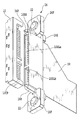
- a receptacle member 16 molded from a resin material as an example of a receptacle member according to the present invention has one end of a cable 18 to be described later as a slit as a contact accommodating portion in the receptacle member 16.
- a male socket portion 16RH connected to the plug portion 10 of the disk pack described above and a flange portion 16F that forms an outer portion of the slit 16Sbi adjacent to the socket portion 16RH.
- the cable 18 is, for example, a flexible conductor such as a flat cable (FFC), a flexible printed circuit (FPC), or a fine coaxial cable, and a contact pad group connected to a contact terminal is one end. Is formed.
- FFC flat cable
- FPC flexible printed circuit
- fine coaxial cable a contact pad group connected to a contact terminal is one end. Is formed.
- the slider member 16K is arranged so as to be slidable with respect to the cable connection end portion of the receptacle member 16.
- the slider member 16K has a pressing portion 16KP that presses the contact pad group of the cable 18 against a first movable piece portion 26K of a contact terminal 26ai to be described later.
- the pressing portion 16KP is supported so as to be slidable with respect to the slot 16Q (see FIG. 9) and the notch portion 16C of each partition wall 16wi.
- Guide walls 16KGW (see FIG. 6) for positioning the contact pad group of the cable 18 with respect to the first movable piece portion 26K of the contact terminal 26ai are formed on both side portions on the proximal end side of the pressing portion 16KP. Yes.
- lock / unlock claw portions 16Kn are integrally formed on both sides of the pressing portion 16KP, as shown in an enlarged manner in FIG. 10, lock / unlock claw portions 16Kn are integrally formed.
- the elastically displaceable lock / unlock claw portion 16Kn has a locking portion 16na at its tip.
- the locking portion 16na is inserted into the hole 16H formed in the receptacle member 16, the locking portion 16na is selectively locked to a claw portion 16N formed on the inner peripheral surface of the hole 16H.
- a locking portion 16nb that is selectively locked to the claw portion 16N is formed between the locking portion 16na and the root portion of the lock / unlock claw portion 16Kn.
- the slider member 16K becomes an unlocked position in which one end of the cable 18 is detachable when the locking portion 16na is locked to the claw portion 16N.
- the slider member 16K has a lock position that holds the state where one end of the cable 18 is electrically connected to the contact. It shall be taken.
- the slider member 16K is shown in a locked position.
- contact terminals 26ai are arranged at predetermined intervals corresponding to the arrangement of contact pad groups of the plug portion 10 in the slits 16Sai and 16Sbi formed in each slot. Further, as shown in FIG. 7, the adjacent slits 16Sai and 16Sbi are partitioned by a partition wall 16wi. The slits 16Sai and 16Sbi formed opposite to each other on a common straight line communicate with each other. An end of the slit 16Sbi where the slider member 16K is inserted is open. Each slit 16Sai opens toward the slots 16SLa and 16SLb.
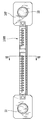
- the contact terminals 26ai arranged in the slits 16Sai and 16Sbi, as shown in enlarged view in FIG. 1 and FIG. 2, are formed by press working with a thin metal material, and are fixedly inserted and fixed into the slit 16Sbi.
- the first movable piece portion 26K having one end connected to the fixed portion 26F and the other end having a contact portion 26Kc that contacts the contact pad of the cable 18, and one end adjacent to the first movable piece portion 26K.
- the second movable piece portion 26P is connected to the other end of the plug portion 10 and has a contact portion 26Pc that contacts the contact pad 10cp of the plug portion 10 at the other end.
- One end of the connecting portion 26PF is formed on a common plane integrally with the fixed portion 26F, and the other end of the connecting portion 26PF is bent in one direction so as to be substantially perpendicular to the common plane. .
- the contact portion 26Kc of the first movable piece portion 26K is elastically displaceable, and is formed on the same plane as one end of the connecting portion 26PF and the fixed portion 26F.
- the contact portion 26Pc of the second movable piece portion 26P that is curved in a convex shape toward the fixed portion 26F is shown in FIG.
- the fixed portion 26F is formed at a position displaced by a predetermined distance.
- a hook-shaped portion 26f that is locked to the periphery of the opening end of the slit 16Sbi is formed at one end of the fixing portion 26F.
- the rising height Hk of the first movable piece portion 26K is set smaller than the rising height Hp of the second movable piece portion 26P. .
- the slider member 16K When attaching the contact terminal 26ai to the slits 16Sbi and 16Sai, the slider member 16K is inserted into the slit 16Sbi from the second movable piece portion 26P side of the contact terminal 26ai in a state where the slider member 16K is detached from the receptacle member 16.
- the contact terminal 26ai is positioned by the hook-like portion 26f being locked to the peripheral edge of the opening end of the slit 16Sbi.
- a pair of fixtures 20 for fixing the receptacle member 16 to the above-described recording medium housing is provided on the slider member 16K side at both ends of the flange portion 16F.
- the fixture 20 is inserted into the peg portion 24 integrally formed at both ends of the flange portion 16 ⁇ / b> F, and is inserted into the peg portion 24 to record the tip of each claw portion of the peg portion.
- the lock / unlock member 22 is selectively locked or unlocked with respect to the periphery of a hole (not shown) of the medium housing.
- the peg portion 24 has four claw portions 24N as shown in FIG.
- the four claw portions 24N are formed by being equally divided in the circumferential direction integrally with one end of a cylindrical portion formed at a predetermined interval inside the hole of the flange portion 16F.
- claw part 24N can be elastically displaced to radial direction, and is formed so that it may protrude from a hole, as FIG. 3 shows.
- the cylindrical portion is connected to the periphery of the hole at two locations. Grooves are formed obliquely in the connecting portion.
- a protrusion (not shown) that is engaged with an outer peripheral surface of a lock / unlock member 22 to be described later is formed in the cylindrical portion described above.
- the resin lock / unlock member 22 includes a columnar shaft portion having a plurality of annular ridges, and a flange portion formed concentrically at one end of the shaft portion.
- the diameter of the shaft portion is set slightly smaller than the inner diameter of the cylindrical portion in the peg portion 24 described above. As a result, the shaft portion is slidably supported in the cylindrical portion of the peg portion 24.
- Two raised portions are formed adjacent to each other at a predetermined interval in the vicinity of the other end of the outer peripheral surface of the shaft portion.
- another raised portion is formed on the outer peripheral surface adjacent to the flange portion 22F.
- a pair of raised portions that extend along the axial direction of the shaft portion across the above-described raised portions on the outer peripheral surface of the shaft portion are formed to face each other. The pair of raised portions are engaged with the grooves described above. As a result, rotation and bias of the lock / unlock member 22 are restricted, and smooth sliding of the lock / unlock member 22 is obtained.
- the claw portion 24N is inserted until the tip of the claw portion 24N of the peg portion 24 penetrates the hole of the recording medium housing.
- the tip of the shaft portion of the lock / unlock member 22 is inserted from the socket portion 16RH side to a predetermined position in the cylindrical portion.
- the lock / unlock member 22 is in a so-called temporary lock state. Since the lock / unlock member 22 is held in the peg portion 24, there is no possibility of dropping and losing during assembly.
- the receptacle member 16 can be individually wrapped while the lock / unlock member 22 is held in the peg portion 24, the packaging of the receptacle member 16 in physical distribution is simplified.
- the tip of the lock / unlock member 22 is pushed further.
- the displacement in the direction in which the tip of the claw portion 24N is detached from the peripheral edge of the hole, that is, the direction in which the tip of the claw portion 24N is adjacent to each other along the radial direction is restricted, so that impact or the like acts on the receptacle member 16.
- the other raised portion of the lock / unlock member 22 is locked to the protrusion in the cylindrical portion. Thereby, the lock / unlock member 22 is in a so-called locked state.
- the slider member 16K is pushed into the slit Sbi and the notch 16C as shown in FIGS. As a result, the slider member 16K is locked, and the contact pad of the cable 18 is electrically connected to the contact portion 26Kc of the first movable piece portion 26K.
- the disc pack is electrically connected to other electrical components via the cable 18 without requiring a wiring board or the like. Will be. Further, since the first movable piece portion 26K and the second movable piece portion 26P are integrally formed adjacent to each other, the overall length L shown in FIG. 1 can be further reduced, and therefore the receptacle member 16 can be downsized. It will be.
- the contact terminal is not limited to such an example, and may be, for example, the contact terminal 36ai shown in FIG.
- Each contact terminal 36ai shown in FIG. 14 is disposed in each slit formed in the flange portion 16′F and the socket portion 16′RH in the receptacle member 16 ′ as shown in FIGS. .
- the slider member has the same configuration as the slider member 16K described above.
- the contact terminal 36ai is formed by press working with a thin metal material, and is fixed to a fixed portion 36F that is press-fitted into a slit and fixed, and one end is connected to the fixed portion 36F, and the other end contacts a contact pad 36Kc of the cable 18.
- a first movable piece portion 36K having one end connected to the first movable piece portion 36K through a connecting portion 36PF adjacent to the first movable piece portion 36K, and a contact portion 36Pc contacting the contact pad 10cp of the plug portion 10 at the other end.
- a second movable piece portion 36P is formed by press working with a thin metal material, and is fixed to a fixed portion 36F that is press-fitted into a slit and fixed, and one end is connected to the fixed portion 36F, and the other end contacts a contact pad 36Kc of the cable 18.
- a first movable piece portion 36K having one end connected to the first movable piece portion 36K through a connecting portion 36PF adjacent to the first
- One end of the connecting portion 36PF is formed on a common plane integrally with the fixed portion 36F, and the other end of the connecting portion 36PF is bent in one direction so as to be substantially perpendicular to the common plane. .
- the contact portion 36Kc of the first movable piece portion 36K is elastically displaceable, and is formed on the same plane as one end of the connecting portion 36PF and the fixed portion 36F.
- the contact portion 36Pc of the second movable piece portion 36P that is curved in a convex shape in the opposite direction to the fixed portion 36F side. Is formed at a position deviated by a predetermined distance from the fixed portion 36F. Further, the position of the contact portion 36Pc is set to a position that is lowered to the fixed portion side by a predetermined dimension compared to the position of the other end of the connecting portion 36PF. At one end of the fixed portion 36F, a hook-like portion 36f that is locked to the periphery of the opening end of the slit is formed.
- FIG. 17 shows another example of the recording medium connecting connector according to the present invention.
- the slider member 16K is provided to be slidable substantially parallel to the extending direction of the socket portion 16RH, whereas in the example shown in FIG.
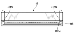
- the slider member 46K is provided to be slidable substantially perpendicular to the extending direction of the socket portion 46RH.
- one end of the cable 18 is connected to the receptacle member 46 as in the above example.
- a receptacle member 46 formed of a resin material as another example of a receptacle member according to the present invention has a slit as a contact accommodating portion in the receptacle member 46 as shown in an enlarged view in FIG. 19.
- a male socket portion 46RH connected to the plug portion 10 of the disk pack.
- the slit 16Sai and the inside of the notch 46C of each partition wall 46wi are slidably supported.
- the slot 46SLc opens on one surface that is substantially perpendicular to the end surface of the receptacle member 46 where the slots 46SLa and 46SLb open.
- the contact pad group of the cable 18 is positioned with respect to the first movable piece portion 56K of the contact terminal 56ai on both sides of the branched pressing portions 46Kb and 46Ka on the proximal end side.
- a guide wall 46KGW is formed.
- lock / unlock claw portions 46Kn are integrally formed on both sides of the pressing portion.
- the lock / unlock claw portion 46Kn has a locking portion at its tip.
- the locking portion is selectively locked to a claw portion 46N formed on the receptacle member 46. Accordingly, as shown in FIG. 21, the slider member 46K maintains a state in which one end of the cable 18 is electrically connected to the contact terminal when the above-described locking portion is locked to the claw portion 46N. The locked position is assumed.
- the socket portion 46RH extends substantially perpendicular to the sliding direction of the slider member 46K, and has elongated slots 46SLa and 46SLb into which the contact pad group of the plug portion 10 is inserted. is doing.
- Positioning pins 46P are integrally formed on both side portions of the socket portion 46RH.
- One end of a contact terminal 56ai (i 1 to n, n is a positive integer), which will be described later, is exposed in the slots 46SLa and 46SLb.
- the slots 46SLa and 46SLb are separated from each other by a partition wall.
- each slit 46Sai formed in each slot contact terminals 56ai are arranged at a predetermined interval corresponding to the arrangement of the contact pad group of the plug portion 10. Further, the adjacent slits 46Sai are partitioned by a partition wall 46wi. The slit 16Sai and the slot 46SLc communicate with each other. Each slit 46Sai opens toward the slots 46SLa and 46SLb.
- the contact terminal 56ai disposed in the slit 46Sai is formed by press working with a thin metal material, and is press-fitted and fixed to the slider member 46K side portion of the slit 46Sai as shown in an enlarged manner in FIGS.
- a second movable piece portion 56P having a contact portion 56Pc that contacts the contact pad 10cp of the plug portion 10 at the other end.
- the connecting portion 56PF is bent substantially perpendicular to the plane of the fixed portion 56F and formed at one end of the fixed portion 56F.
- the contact portion 56Kc of the first movable piece portion 56K is elastically displaceable and is formed on the same plane as the connecting portion 56PF.
- the contact portion 56Pc of the second movable piece portion 56P that is curved in a convex shape in the opposite direction to the fixed portion 56F side.
- the first movable piece portion 56K and the connecting portion 56F are formed at a position deviated by a predetermined distance.
- the second movable piece portion 56P in the contact terminal 56ai extends beyond the rising portion of the first movable piece portion 56K to the partition wall 46Pa on the slots 46SLa and 46SLb side of the socket portion 46RH. It is extended.
- the contact terminal 56ai When attaching the contact terminal 56ai to the slit 46Sai, the contact terminal 56ai is inserted into the slit 16Sai from the second movable piece portion 56P side of the contact terminal 56ai in a state where the slider member 46K is detached from the receptacle member 46. Is done. Accordingly, as shown in FIG. 19, the tip of the second movable piece portion 56P of the contact terminal 56ai is engaged with the positioning wall 46pa in the socket portion 46RH.
- the slider member 46K is pushed into the slit Sai and the cutout portion 46C. Thereby, the slider member 46K is brought into the above-described locked state, and the contact pad of the cable 18 is electrically connected to the contact portion 56Kc of the first movable piece portion 56K.
Landscapes
- Coupling Device And Connection With Printed Circuit (AREA)
Abstract
SATA規格に準拠したレセプタクル部材(16)が、ケーブル(18)の一端に接続される第1の可動片部(26K)と、プラグ(10)のコンタクトパッド(10cp)に接続される第2の可動片部(26P)とを備えるもの。
Description
本発明は、記録媒体を着脱可能に接続するレセプタクル部材、および、それが用いられる記録媒体接続用コネクタに関する。
情報通信機器において、記録媒体としてのハードディスクドライブ(HDD)または密閉型のハードディスクパック等を筐体内に内蔵するものが実用に供されている。ハードディスクパックにおける一端には、例えば、特許文献1にも示されるように、接続用プラグ(特許文献1においてハードディスク側脱着部とも呼ばれる)が設けられている。接続用プラグとしては、例えば、SATA規格に準拠し成形された接続用プラグが広く利用されている。
そのような接続用プラグは、所定の基板上に半田付け固定されるベースコネクタに接続される。そのようなベースコネクタは、例えば、特許文献2および特許文献3にも示されるように、接続用プラグが嵌合される嵌合口、および、接続用プラグのパッドと基板の導電層とを電気的に接続する複数個のコンタクトを備えている。各コンタクトは、一端に半田付け固定端子を有している。
しかしながら、特許文献1にも示されるような、従来のベースコネクタにおいては、ベースコネクタが固定される基板が必要とされるので製造コストが嵩むという問題点を伴う。また、基板の配置により、情報通信機器内における配置設計の自由度が、制限される場合がある。
以上の問題点を考慮し、本発明は、記録媒体を着脱可能に接続するレセプタクル部材、および、それが用いられる記録媒体接続用コネクタであって、コネクタの製造コストを低減することができるレセプタクル部材、および、それが用いられる記録媒体接続用コネクタを提供することを目的とする。
上述の目的を達成するために、本発明に係るレセプタクル部材は、記録媒体のプラグ部が着脱可能に接続されるスロット部を有するソケット部と、ソケット部と一体に形成され、ケーブルの一端が着脱可能に接続されるケーブル接続端部と、ソケット部およびケーブル接続端部の内側であって、スロット部に連通するコンタクト端子収容部と、コンタクト端子収容部に配される複数のコンタクト端子と、を有し、コンタクト端子は、コンタクト端子収容部に固定される固定部と、一端が該固定部と一体に共通の平面上に形成され、ケーブルのコンタクトパッドに当接する接点部を有する第1の可動片部と、一端が屈曲した連結部を介して前記固定部と一体に形成され、プラグ部のコンタクトパッドに当接する接点部を、第1の可動片部の接点部に対し偏倚させて有する第2の可動片部とからなることを特徴とする。
また、本発明に係る記録媒体接続用コネクタは、記録媒体の入出力部に接続されるプラグ部と、プラグ部が着脱可能に接続されるスロット部を有するソケット部と、ソケット部と一体に形成され、ケーブルの一端が着脱可能に接続されるケーブル接続端部と、ソケット部およびケーブル接続端部の内側であって、スロット部に連通するコンタクト端子収容部と、コンタクト端子収容部に配される複数のコンタクト端子と、を有するレセプタクル部材とを備え、コンタクト端子は、コンタクト端子収容部に固定される固定部と、一端が固定部と一体に共通の平面上に形成され、ケーブルのコンタクトパッドに当接する接点部を有する第1の可動片部と、一端が屈曲した連結部を介して固定部と一体に形成され、プラグ部のコンタクトパッドに当接する接点部を、第1の可動片部の接点部に対し偏倚させて有する第2の可動片部とからなることを特徴とする。
以上の説明から明らかなように、本発明に係るレセプタクル部材、および、それが用いられる記録媒体接続用コネクタによれば、コンタクト端子は、コンタクト端子収容部に固定される固定部と、一端が固定部と一体に共通の平面上に形成され、ケーブルのコンタクトパッドに当接する接点部を有する第1の可動片部と、一端が屈曲した連結部を介して固定部と一体に形成され、プラグ部のコンタクトパッドに当接する接点部を、第1の可動片部の接点部に対し偏倚させて有する第2の可動片部とからなるので配線基板が不要とされ、従って、コネクタの製造コストを低減することができる。
図3は、本発明に係る記録媒体接続用コネクタの一例を、それに接続されるケーブルの一部とともに拡大して示す。
図3において、記録媒体接続用コネクタは、例えば、図示が省略される車載用情報通信機器の内部に配置される記録媒体用ハウジングに配置される。その記録媒体用ハウジングは、密閉型記録媒体としてのディスクパックを着脱可能に収容する記録媒体収容部を有している。そのディスクパックは、その内部に記録媒体として所定の記憶容量を有する円盤状の磁気記録媒体、および、ドライバ等を内蔵している。記録媒体接続用コネクタは、プラグ部10および後述するレセプタクル部材16から構成されている。
ディスクパックにおける一端側の端面には、レセプタクル部材16のソケット部が着脱可能に係合されるプラグ部10が設けられている。プラグ部10は、例えば、図4に拡大されて示されるように、SATA規格に準拠した間隔およびサイズの複数のコンタクトパッド10cpを有している。ディスクパックの着脱方向に対し略直交する方向に配列される複数のコンタクトパッド10cpは、隔壁により、二つの群に区切られている。
本発明に係るレセプタクル部材の一例としての樹脂材料で成形されるレセプタクル部材16は、図7に拡大されて示されるように、後述するケーブル18の一端をレセプタクル部材16内のコンタクト収容部としてのスリット16Sbi(i=1~n,nは正の整数),および、各隔壁16wi(i=1~n,nは正の整数)の切欠部16C内に対し着脱可能に固定するスライダー部材16Kと、上述のディスクパックのプラグ部10内に接続される雄型のソケット部16RHと、ソケット部16RHに隣接してスリット16Sbiの外郭部を形成するフランジ部16Fとを含んで構成されている。
ケーブル18は、例えば、フラットケーブル(FFC)、または、フレキシブル配線基板(FPC;flexible printed circuit)、あるいは、細線同軸ケーブル等の可撓性導体とされ、コンタクト端子に接続されるコンタクトパッド群が一端に形成されている。
スライダー部材16Kは、レセプタクル部材16におけるケーブル接続端部に対して摺動可能に配されている。
スライダー部材16Kは、ケーブル18のコンタクトパッド群を後述するコンタクト端子26aiの第1の可動片部26Kに対し押圧する押圧部16KPを有している。押圧部16KPは、図8に示されるように、スロット16Q(図9参照),および、各隔壁16wiの切欠部16C内に対して摺動可能に支持されている。その押圧部16KPの基端側における両側部には、それぞれ、ケーブル18のコンタクトパッド群をコンタクト端子26aiの第1の可動片部26Kに対し位置決めするガイド壁16KGW(図6参照)が形成されている。
その押圧部16KPの両脇には、図10に拡大されて示されるように、ロック/アンロック爪部16Knが一体に形成されている。弾性変位可能なロック/アンロック爪部16Knは、係止部16naをその先端に有している。係止部16naは、レセプタクル部材16内に形成される孔16Hに挿入される場合、その孔16Hの内周面に形成される爪部16Nに選択的に係止される。また、係止部16naとロック/アンロック爪部16Knの根元部分との間には、爪部16Nに選択的に係止される係止部16nbが形成されている。
これにより、スライダー部材16Kは、図10に示されるように、上述の係止部16naが爪部16Nに係止されるとき、ケーブル18の一端を着脱可能な状態とするアンロック位置となる。一方、係止部16nbが爪部16Nに係止されるとき、図13に示されるように、スライダー部材16Kは、ケーブル18の一端をコンタクトに対し電気的に接続する状態を保持するロック位置をとるものとされる。
なお、図3および図4においては、スライダー部材16Kがロック位置とされる状態を示す。
ソケット部16RHは、図4に拡大されて示されるように、後述のフランジ部16Fの端面に対して略垂直に突出し、プラグ部10のコンタクトパッド群が挿入される細長いスロット16SLaおよび16SLbを有している。ソケット部16RHの両側部には、隣接して位置決めピン16Pが一体に形成されている。そのスロット16SLaおよび16SLb内には、後述するコンタクト端子26ai(i=1~n,nは正の整数)の一端が露出している。スロット16SLaおよび16SLb相互間は、隔壁により、区切られている。また、各スロット内に形成される各スリット16Saiおよび16Sbiには、コンタクト端子26aiが、プラグ部10のコンタクトパッド群の配列に対応した所定の間隔で配列されている。さらに、図7に示されるように、隣接するスリット16Saiおよび16Sbi相互間は、隔壁16wiにより仕切られている。共通の直線上に相対向して形成されるスリット16Saiおよび16Sbiは、互いに連通している。スリット16Sbiにおけるスライダー部材16Kが挿入される端部は、開口している。また、各スリット16Saiは、スロット16SLaおよび16SLbに向けて開口している。
スリット16Saiおよび16Sbi内に配されるコンタクト端子26aiは、図1および図2に拡大されて示されるように、薄板金属材料でプレス加工により成形され、スリット16Sbiに圧入され固定される固定部26Fと、一端が固定部26Fに連結され、他端にケーブル18のコンタクトパッドに当接する接点部26Kcを有する第1の可動片部26Kと、一端が第1の可動片部26Kに隣接して連結部26PFを介して連結され、他端にプラグ部10のコンタクトパッド10cpに当接する接点部26Pcを有する第2の可動片部26Pとから構成されている。
連結部26PFの一端は、固定部26Fと一体に共通の平面上に形成され、また、連結部26PFの他端は、その共通の平面に対し略垂直となるように一方向に屈曲されている。
第1の可動片部26Kの接点部26Kcは、弾性変位可能とされ、連結部26PFの一端、および、固定部26Fと共通の平面上にあるように形成されている。
第2の可動片部26Pの一端が、連結部26PFの他端に連なって形成されているので固定部26F側に凸状に湾曲した第2の可動片部26Pの接点部26Pcは、図2に示されるように、固定部26Fに対し所定距離、偏倚した位置に形成されることとなる。
固定部26Fの一端には、図7に示されるように、スリット16Sbiの開口端の周縁に係止される鉤状部26fが形成されている。
また、コンタクト端子26aiは、図1に示されるように、第1の可動片部26Kの立ち上がり高さHkが、第2の可動片部26Pの立ち上がり高さHpに比べて小に設定されている。
コンタクト端子26aiをスリット16Sbiおよび16Saiに装着するにあたっては、スライダー部材16Kがレセプタクル部材16に対し取り外された状態において、コンタクト端子26aiの第2の可動片部26P側からスリット16Sbi内に挿入される。これにより、コンタクト端子26aiは、鉤状部26fがスリット16Sbiの開口端の周縁に係止されることによって位置決めされることとなる。
フランジ部16Fの両端におけるスライダー部材16K側には、レセプタクル部材16を上述の記録媒体用ハウジングに対し固定するための固定具20が一対設けられている。
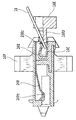
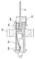
固定具20は、図5および図6に示されるように、フランジ部16Fの両端に一体に形成されるペグ部24と、ペグ部24内に挿入され、ペグ部の各爪部の先端を記録媒体用ハウジングの孔(不図示)の周縁に対し選択的にロック状態またはアンロック状態とするロック/アンロック部材22とから構成されている。
ペグ部24は、図6に示されるように、4本の爪部24Nを有している。4本の爪部24Nは、フランジ部16Fの孔の内側に所定の間隔をもって形成される円筒部の一端に一体に円周方向に均等分割されて形成される。各爪部24Nは、半径方向に弾性変位可能とされ、図3に示されるように、孔から突出するように形成されている。その円筒部は、その孔の周縁と2箇所で連結されている。その連結部分には、溝が斜めに形成されている。上述の円筒部内には、後述するロック/アンロック部材22の外周面に係合される突起部(不図示)が形成されている。
樹脂製のロック/アンロック部材22は、複数個の環状の隆起部を有する円柱状の軸部と、その軸部の一端に同心円状に形成されるフランジ部とから構成されている。
軸部の直径は、上述のペグ部24における円筒部の内径よりも若干小に設定されている。これにより、軸部は、ペグ部24における円筒部内を摺動可能に支持されることとなる。
軸部の外周面における他端近傍に、二つの隆起部が所定の間隔をもって隣接して形成されている。また、他の1つの隆起部が、フランジ部22Fに隣接して外周面上に形成されている。さらに、軸部の外周面における上述の各隆起部を横切り、軸部の軸線方向に沿って延びる一対の隆起部が相対向して形成されている。その一対の隆起部は、上述の溝に係合される。これにより、ロック/アンロック部材22の自転および偏りが規制されるとともに、ロック/アンロック部材22の円滑な摺動が得られる。
固定具20により、レセプタクル部材16を記録媒体用ハウジングに固定するにあたっては、先ず、ペグ部24の爪部24Nの先端が記録媒体用ハウジングの孔を貫通するまで爪部24Nが挿入される。次に、ロック/アンロック部材22の軸部の先端が、ソケット部16RH側から円筒部内の所定位置まで挿入される。これにより、軸部の隆起部と隆起部相互間の部分が、円筒部内の突起部に係止される。その結果、ロック/アンロック部材22は、所謂、仮ロック状態とされる。ロック/アンロック部材22がペグ部24内に保持されるので組み立て途中で脱落して紛失する虞がない。また、ロック/アンロック部材22がペグ部24内に保持された状態でレセプタクル部材16を個別に包装することも可能となるので物流におけるレセプタクル部材16の荷姿も簡便化される。
続いて、ロック/アンロック部材22の先端が、さらに押し込まれる。これにより、爪部24Nの先端が孔の周縁から離脱する方向、即ち、爪部24Nの先端における互いに半径方向に沿って近接する方向の変位が規制されるので衝撃等がレセプタクル部材16に作用した場合であってもレセプタクル部材16が脱落する虞がない。また、ロック/アンロック部材22における他の1つの隆起部が上述の円筒部内の突起部に係止される。これにより、ロック/アンロック部材22は、所謂、ロック状態とされる。
斯かる構成において、ケーブル18の一端をレセプタクル部材16に接続するにあたっては、図8および図9に示されるように、先ず、スライダー部材16Kがアンロック状態とされ、ケーブル18の一端が第1の可動片部26Kの接点部26Kcとスライダー部材16Kの押圧部16KPとの間に挿入される。
次に、スライダー部材16Kが、図11および図13に示されるように、スリットSbiおよび切欠部16C内に押し込まれる。これにより、スライダー部材16Kがロック状態とされ、また、ケーブル18のコンタクトパッドが第1の可動片部26Kの接点部26Kcに電気的に接続されることとなる。
従って、ディスクパックのプラグ部10が、レセプタクル部材16のソケット部16RHに装着されることにより、配線基板等を要することなく、ディスクパックは、ケーブル18を介して他の電装品に電気的に接続されることとなる。また、第1の可動片部26Kおよび第2の可動片部26Pが一体に隣接して形成されるので図1に示される全長Lをより小さくでき、従って、レセプタクル部材16の小型化が図られることとなる。
コンタクト端子は、斯かる例に限られることなく、例えば、図14に示されるコンタクト端子36aiであってもよい。
図14に示される各コンタクト端子36aiは、図15および図16に示されるような、レセプタクル部材16’におけるフランジ部16’Fおよびソケット部16’RH内に形成される各スリット内に配置される。なお、スライダー部材は、上述のスライダー部材16Kと同様な構成を有するものとされる。
コンタクト端子36aiは、薄板金属材料でプレス加工により成形され、スリットに圧入され固定される固定部36Fと、一端が固定部36Fに連結され、他端にケーブル18のコンタクトパッドに当接する接点部36Kcを有する第1の可動片部36Kと、一端が第1の可動片部36Kに隣接して連結部36PFを介して連結され、他端にプラグ部10のコンタクトパッド10cpに当接する接点部36Pcを有する第2の可動片部36Pとから構成されている。
連結部36PFの一端は、固定部36Fと一体に共通の平面上に形成され、また、連結部36PFの他端は、その共通の平面に対し略垂直となるように一方向に屈曲されている。
第1の可動片部36Kの接点部36Kcは、弾性変位可能とされ、連結部36PFの一端、および、固定部36Fと共通の平面上にあるように形成されている。
第2の可動片部36Pの一端が、連結部36PFの他端に連なって形成されているので固定部36F側とは反対方向に凸状に湾曲した第2の可動片部36Pの接点部36Pcは、固定部36Fに対し所定距離、偏倚した位置に形成されることとなる。また、接点部36Pcの位置は、連結部36PFの他端の位置に比べて所定の寸法だけ固定部側に下がった位置に設定されている。固定部36Fの一端には、スリットの開口端の周縁に係止される鉤状部36fが形成されている。
図17は、本発明に係る記録媒体接続用コネクタの他の一例を示す。
図3に示される例においては、スライダー部材16Kは、ソケット部16RHの延在する方向に対し略平行に摺動可能に設けられているのに対し、一方、図17に示される例においては、スライダー部材46Kは、ソケット部46RHの延在する方向に対し略垂直に摺動可能に設けられている。なお、図17に示される例においても上述の例と同様にケーブル18の一端がレセプタクル部材46に接続される。
本発明に係るレセプタクル部材の他の例としての樹脂材料で成形されるレセプタクル部材46は、図19に拡大されて示されるように、ケーブル18の一端をレセプタクル部材46内のコンタクト収容部としてのスリット46Sai(i=1~n,nは正の整数),および、各隔壁46wi(i=1~n,nは正の整数)の切欠部46C内に対し着脱可能に固定するスライダー部材46Kと、上述のディスクパックのプラグ部10内に接続される雄型のソケット部46RHとを含んで構成されている。
ケーブル18のコンタクトパッド群を後述するコンタクト端子56aiの第1の可動片部56Kに対し押圧するスライダー部材46Kにおける押圧部46Kbは、図19に示される矢印の示す方向に沿って、スロット46SLcを介してスリット16Sai,および、各隔壁46wiの切欠部46C内に対して摺動可能に支持されている。スロット46SLcは、レセプタクル部材46のスロット46SLaおよび46SLbが開口する端面に対し略垂直となる一方の表面に開口している。
その分岐した押圧部46Kbおよび46Kaの基端側における両側部には、それぞれ、図20に示されるように、ケーブル18のコンタクトパッド群をコンタクト端子56aiの第1の可動片部56Kに対し位置決めするガイド壁46KGWが形成されている。
その押圧部の両脇には、図21に拡大されて示されるように、ロック/アンロック爪部46Knが一体に形成されている。ロック/アンロック爪部46Knは、係止部をその先端に有している。係止部は、レセプタクル部材46に形成される爪部46Nに選択的に係止される。これにより、スライダー部材46Kは、図21に示されるように、上述の係止部が爪部46Nに係止されるとき、ケーブル18の一端をコンタクト端子に対し電気的に接続する状態を保持するロック位置をとるものとされる。
なお、図19および図21においては、スライダー部材46Kがロック位置とされる状態を示す。
ソケット部46RHは、図17および図18に示されるように、スライダー部材46Kの摺動方向に対し略垂直に延在し、プラグ部10のコンタクトパッド群が挿入される細長いスロット46SLaおよび46SLbを有している。ソケット部46RHの両側部に位置決めピン46Pが一体に形成されている。そのスロット46SLaおよび46SLb内には、後述するコンタクト端子56ai(i=1~n,nは正の整数)の一端が露出している。スロット46SLaおよび46SLb相互間は、隔壁により、区切られている。また、各スロット内に形成される各スリット46Saiには、コンタクト端子56aiが、プラグ部10のコンタクトパッド群の配列に対応した所定の間隔で配列されている。さらに、隣接するスリット46Sai相互間は、隔壁46wiにより仕切られている。スリット16Saiおよびスロット46SLcは、互いに連通している。また、各スリット46Saiは、スロット46SLaおよび46SLbに向けて開口している。
スリット46Sai内に配されるコンタクト端子56aiは、図22および図23に拡大されて示されるように、薄板金属材料でプレス加工により成形され、スリット46Saiにおけるスライダー部材46K側部分に圧入され固定される固定部56Fと、一端が固定部56Fに連結部56PFを介して連結され、他端にケーブル18のコンタクトパッドに当接する接点部56Kcを有する第1の可動片部56Kと、一端が固定部56Fに連結され、他端にプラグ部10のコンタクトパッド10cpに当接する接点部56Pcを有する第2の可動片部56Pとから構成されている。
連結部56PFは、図23に示されるように、固定部56Fの平面に対して略垂直に折り曲げられて固定部56Fの一端に形成されている。
第1の可動片部56Kの接点部56Kcは、弾性変位可能とされ、連結部56PFと共通の平面上にあるように形成されている。
第2の可動片部56Pの一端が、固定部56Fの他端に連なって形成されているので固定部56F側とは反対方向に凸状に湾曲した第2の可動片部56Pの接点部56Pcは、図23に示されるように、第1の可動片部56Kおよび連結部56Fに対し所定距離、偏倚した位置に形成されることとなる。
また、コンタクト端子56aiにおける第2の可動片部56Pは、図19に示されるように、第1の可動片部56Kの立ち上がり部分を越えてソケット部46RHのスロット46SLaおよび46SLb側の仕切壁46Paまで延在している。
コンタクト端子56aiをスリット46Saiに装着するにあたっては、スライダー部材46Kがレセプタクル部材46に対し取り外された状態において、コンタクト端子56aiは、コンタクト端子56aiの第2の可動片部56P側からスリット16Sai内に挿入される。これにより、図19に示されるように、コンタクト端子56aiの第2の可動片部56Pの先端は、ソケット部46RH内の位置決め壁46paに係合される。
なお、図17に示される例においては、上述のような固定具を備えるものとされるが、図示が省略されている。
斯かる構成において、ケーブル18の一端をレセプタクル部材46に接続するにあたっては、先ず、スライダー部材46Kがアンロック状態とされ、ケーブル18の一端が第1の可動片部56Kの接点部56Kcとスライダー部材46Kの押圧部46Kbとの間に挿入される。
次に、スライダー部材46Kが、スリットSaiおよび切欠部46C内に押し込まれる。これにより、スライダー部材46Kが上述のロック状態とされ、また、ケーブル18のコンタクトパッドが第1の可動片部56Kの接点部56Kcに電気的に接続されることとなる。
Claims (8)
- 記録媒体のプラグ部が着脱可能に接続されるスロット部を有するソケット部と、該ソケット部と一体に形成され、ケーブルの一端が着脱可能に接続されるケーブル接続端部と、前記ソケット部および前記ケーブル接続端部の内側であって、前記スロット部に連通するコンタクト端子収容部と、前記コンタクト端子収容部に配される複数のコンタクト端子と、を有し、
前記コンタクト端子は、前記コンタクト端子収容部に固定される固定部と、一端が該固定部と一体に共通の平面上に形成され、前記ケーブルのコンタクトパッドに当接する接点部を有する第1の可動片部と、一端が屈曲した連結部を介して前記固定部と一体に形成され、前記プラグ部のコンタクトパッドに当接する接点部を、前記第1の可動片部の接点部に対し偏倚させて有する第2の可動片部とからなることを特徴とするレセプタクル部材。 - 前記第2の可動片部は、前記連結部の一端に対し片持ち梁状に形成されることを特徴とする請求項1記載のレセプタクル部材。
- 前記コンタクト端子における前記第2の可動片部は、金属材料で打ち抜かれた後、折り曲げられて形成され、前記第1の可動片部は、該金属材料で打ち抜かれて形成されることを特徴とする請求項1記載のレセプタクル部材。
- 前記ケーブル接続端部が、前記ソケット部のスロット部に対し略平行、または、略垂直に設けられることを特徴とする請求項1記載のレセプタクル部材。
- 記録媒体の入出力部に接続されるプラグ部と、
前記プラグ部が着脱可能に接続されるスロット部を有するソケット部と、該ソケット部と一体に形成され、ケーブルの一端が着脱可能に接続されるケーブル接続端部と、前記ソケット部および前記ケーブル接続端部の内側であって、前記スロット部に連通するコンタクト端子収容部と、前記コンタクト端子収容部に配される複数のコンタクト端子と、を有するレセプタクル部材とを備え、
前記コンタクト端子は、前記コンタクト端子収容部に固定される固定部と、一端が該固定部と一体に共通の平面上に形成され、前記ケーブルのコンタクトパッドに当接する接点部を有する第1の可動片部と、一端が屈曲した連結部を介して前記固定部と一体に形成され、前記プラグ部のコンタクトパッドに当接する接点部を、前記第1の可動片部の接点部に対し偏倚させて有する第2の可動片部とからなることを特徴とする記録媒体接続用コネクタ。 - 前記第2の可動片部は、前記連結部の一端に対し片持ち梁状に形成されることを特徴とする請求項5記載の記録媒体接続用コネクタ。
- 前記コンタクト端子における前記第2の可動片部は、金属材料で打ち抜かれた後、折り曲げられて形成され、前記第1の可動片部は、該金属材料で打ち抜かれて形成されることを特徴とする請求項5記載の記録媒体接続用コネクタ。
- 前記ケーブル接続端部が、前記ソケット部のスロット部に対し略平行、または、略垂直に設けられることを特徴とする請求項5記載の記録媒体接続用コネクタ。
Applications Claiming Priority (2)
| Application Number | Priority Date | Filing Date | Title |
|---|---|---|---|
| JP2007-331946 | 2007-12-25 | ||
| JP2007331946A JP2009158136A (ja) | 2007-12-25 | 2007-12-25 | レセプタクル部材、および、それが用いられる記録媒体接続用コネクタ |
Publications (1)
| Publication Number | Publication Date |
|---|---|
| WO2009081914A1 true WO2009081914A1 (ja) | 2009-07-02 |
Family
ID=40801215
Family Applications (1)
| Application Number | Title | Priority Date | Filing Date |
|---|---|---|---|
| PCT/JP2008/073354 WO2009081914A1 (ja) | 2007-12-25 | 2008-12-22 | レセプタクル部材、および、それが用いられる記録媒体接続用コネクタ |
Country Status (2)
| Country | Link |
|---|---|
| JP (1) | JP2009158136A (ja) |
| WO (1) | WO2009081914A1 (ja) |
Families Citing this family (1)
| Publication number | Priority date | Publication date | Assignee | Title |
|---|---|---|---|---|
| KR200464846Y1 (ko) | 2010-04-02 | 2013-01-22 | 홍 위 차이 | 전기 커넥터 |
Citations (13)
| Publication number | Priority date | Publication date | Assignee | Title |
|---|---|---|---|---|
| JPS6178079A (ja) * | 1984-09-21 | 1986-04-21 | イー・アイ・デユポン・ドウ・ヌムール・アンド・カンパニー | コネクタ組立体 |
| JPS62183382U (ja) * | 1986-05-13 | 1987-11-20 | ||
| JPH05266952A (ja) * | 1992-03-19 | 1993-10-15 | Matsushita Electric Works Ltd | 電気コネクタ |
| JPH07302646A (ja) * | 1994-05-06 | 1995-11-14 | Hosiden Corp | インターフェイス用コネクタ |
| JPH09199241A (ja) * | 1996-01-19 | 1997-07-31 | Smk Corp | フレキシブル基板の中継用コネクタ |
| JPH10255927A (ja) * | 1997-03-07 | 1998-09-25 | Molex Inc | 平型柔軟ケーブル用電気コネクタ |
| JP2001135392A (ja) * | 1999-10-29 | 2001-05-18 | Smk Corp | フラットケーブルコネクタ |
| JP3093017U (ja) * | 2002-09-25 | 2003-04-18 | 群聯電子股▲ふん▼有限公司 | アダプタ型メモリカード |
| JP2003331957A (ja) * | 2002-05-15 | 2003-11-21 | Union Machinery Co Ltd | コネクタ |
| JP2004127692A (ja) * | 2002-10-02 | 2004-04-22 | Alps Electric Co Ltd | カード用コネクタ装置 |
| JP2005166591A (ja) * | 2003-12-05 | 2005-06-23 | Taiko Denki Co Ltd | 電気コネクタ |
| JP2006185841A (ja) * | 2004-12-28 | 2006-07-13 | Fujitsu Component Ltd | コネクタ |
| JP2006278186A (ja) * | 2005-03-30 | 2006-10-12 | Nec Corp | ハードディスク接続コネクタ |
-
2007
- 2007-12-25 JP JP2007331946A patent/JP2009158136A/ja not_active Withdrawn
-
2008
- 2008-12-22 WO PCT/JP2008/073354 patent/WO2009081914A1/ja active Application Filing
Patent Citations (13)
| Publication number | Priority date | Publication date | Assignee | Title |
|---|---|---|---|---|
| JPS6178079A (ja) * | 1984-09-21 | 1986-04-21 | イー・アイ・デユポン・ドウ・ヌムール・アンド・カンパニー | コネクタ組立体 |
| JPS62183382U (ja) * | 1986-05-13 | 1987-11-20 | ||
| JPH05266952A (ja) * | 1992-03-19 | 1993-10-15 | Matsushita Electric Works Ltd | 電気コネクタ |
| JPH07302646A (ja) * | 1994-05-06 | 1995-11-14 | Hosiden Corp | インターフェイス用コネクタ |
| JPH09199241A (ja) * | 1996-01-19 | 1997-07-31 | Smk Corp | フレキシブル基板の中継用コネクタ |
| JPH10255927A (ja) * | 1997-03-07 | 1998-09-25 | Molex Inc | 平型柔軟ケーブル用電気コネクタ |
| JP2001135392A (ja) * | 1999-10-29 | 2001-05-18 | Smk Corp | フラットケーブルコネクタ |
| JP2003331957A (ja) * | 2002-05-15 | 2003-11-21 | Union Machinery Co Ltd | コネクタ |
| JP3093017U (ja) * | 2002-09-25 | 2003-04-18 | 群聯電子股▲ふん▼有限公司 | アダプタ型メモリカード |
| JP2004127692A (ja) * | 2002-10-02 | 2004-04-22 | Alps Electric Co Ltd | カード用コネクタ装置 |
| JP2005166591A (ja) * | 2003-12-05 | 2005-06-23 | Taiko Denki Co Ltd | 電気コネクタ |
| JP2006185841A (ja) * | 2004-12-28 | 2006-07-13 | Fujitsu Component Ltd | コネクタ |
| JP2006278186A (ja) * | 2005-03-30 | 2006-10-12 | Nec Corp | ハードディスク接続コネクタ |
Also Published As
| Publication number | Publication date |
|---|---|
| JP2009158136A (ja) | 2009-07-16 |
Similar Documents
| Publication | Publication Date | Title |
|---|---|---|
| JP5185204B2 (ja) | ソケット、プラグ、及びコネクタ装置 | |
| US7232329B1 (en) | Cable connector assembly with unitary latch | |
| US6860750B1 (en) | Cable end connector assembly having locking member | |
| US7351106B2 (en) | Electrical connector having an inner printed circuit board | |
| US6722897B1 (en) | Adapter for power connectors | |
| JP4584899B2 (ja) | 電気コネクタ | |
| JP2009043723A (ja) | ソケットコネクタ | |
| US7695304B2 (en) | Electrical connector with latching member | |
| US7780466B1 (en) | Cable assembly with locking member | |
| WO2007094051A1 (ja) | コネクタ | |
| JP2593708B2 (ja) | コネクタ | |
| US6758697B1 (en) | Electrical adapter | |
| JP2001155806A (ja) | フレキシブルな伝送線路一体型コネクタ | |
| WO2009081914A1 (ja) | レセプタクル部材、および、それが用いられる記録媒体接続用コネクタ | |
| US20080188134A1 (en) | Electrical card connector | |
| JPH06203898A (ja) | 小型断路端子 | |
| US20060046574A1 (en) | Electrical connector for cards | |
| US6290513B1 (en) | PC card switchably compatible with 16-bit and 32-bit modes | |
| JPH11307161A (ja) | スプリングピンコネクタ | |
| JP3736692B2 (ja) | 電気コネクタ組立体 | |
| US20080261461A1 (en) | Electrical connector assembly | |
| JP4992736B2 (ja) | 記録媒体用ハウジング、および、それに用いられる位置調節機構 | |
| EP0884802B1 (en) | Terminal et boítier comprenant le terminal | |
| JP2004259051A (ja) | カード用コネクタ装置 | |
| TWI761142B (zh) | 反向連接器 |
Legal Events
| Date | Code | Title | Description |
|---|---|---|---|
| 121 | Ep: the epo has been informed by wipo that ep was designated in this application |
Ref document number: 08864937 Country of ref document: EP Kind code of ref document: A1 |
|
| DPE1 | Request for preliminary examination filed after expiration of 19th month from priority date (pct application filed from 20040101) | ||
| NENP | Non-entry into the national phase |
Ref country code: DE |
|
| 122 | Ep: pct application non-entry in european phase |
Ref document number: 08864937 Country of ref document: EP Kind code of ref document: A1 |