WO2009081519A1 - Vehicle parking assist system and method - Google Patents
Vehicle parking assist system and method Download PDFInfo
- Publication number
- WO2009081519A1 WO2009081519A1 PCT/JP2008/003341 JP2008003341W WO2009081519A1 WO 2009081519 A1 WO2009081519 A1 WO 2009081519A1 JP 2008003341 W JP2008003341 W JP 2008003341W WO 2009081519 A1 WO2009081519 A1 WO 2009081519A1
- Authority
- WO
- WIPO (PCT)
- Prior art keywords
- parking
- vehicle
- recommended
- parking start
- target
- Prior art date
Links
- 238000000034 method Methods 0.000 title claims description 13
- 230000009471 action Effects 0.000 claims description 29
- 230000009466 transformation Effects 0.000 claims description 7
- 238000003384 imaging method Methods 0.000 claims 4
- 230000001131 transforming effect Effects 0.000 claims 3
- 230000015654 memory Effects 0.000 description 6
- 230000008859 change Effects 0.000 description 5
- 230000008569 process Effects 0.000 description 4
- 238000010586 diagram Methods 0.000 description 3
- 230000010365 information processing Effects 0.000 description 1
- 239000004973 liquid crystal related substance Substances 0.000 description 1
- 238000012986 modification Methods 0.000 description 1
- 230000004048 modification Effects 0.000 description 1
- 230000003287 optical effect Effects 0.000 description 1
- 239000007787 solid Substances 0.000 description 1
Images

Classifications
-
- B—PERFORMING OPERATIONS; TRANSPORTING
- B62—LAND VEHICLES FOR TRAVELLING OTHERWISE THAN ON RAILS
- B62D—MOTOR VEHICLES; TRAILERS
- B62D15/00—Steering not otherwise provided for
- B62D15/02—Steering position indicators ; Steering position determination; Steering aids
- B62D15/027—Parking aids, e.g. instruction means
- B62D15/0275—Parking aids, e.g. instruction means by overlaying a vehicle path based on present steering angle over an image without processing that image
-
- B—PERFORMING OPERATIONS; TRANSPORTING
- B62—LAND VEHICLES FOR TRAVELLING OTHERWISE THAN ON RAILS
- B62D—MOTOR VEHICLES; TRAILERS
- B62D15/00—Steering not otherwise provided for
- B62D15/02—Steering position indicators ; Steering position determination; Steering aids
- B62D15/027—Parking aids, e.g. instruction means
- B62D15/028—Guided parking by providing commands to the driver, e.g. acoustically or optically
Definitions
- the present invention relates to a vehicle parking assist system which assists a driving operation at parking a vehicle and a method thereof.
- a system disclosed in Japanese Patent Laid-open Publication No. 2005-239048 is known.
- This system transforms images around the vehicle captured by onboard cameras into an overhead image; and draws and displays on a display device a figure of the vehicle at a position of the vehicle on the overhead image and a parking frame figure at a target parking position set by a driver of the vehicle.
- the system thus enables the driver of the vehicle to easily recognize a path from the current position of the vehicle to the target parking position.
- the vehicle is a vehicle on which the parking assist system is mounted.
- the above-described conventional parking assist system only causes the driver of the vehicle to recognize the path from the current position of the vehicle to the target parking position but is not configured to cause the driver to recognize from which position the driver should start parking to reach the target parking position without performing steering operation during the parking action. Accordingly, the aforementioned conventional system does not provide adequate assistance for inexperienced drivers in driving operations.
- the present invention draws a recommended parking start position which a vehicle can reach with a current value of steering angle of the vehicle unchanged and from which the vehicle can reach the target parking position with the steering angle being constant on an overhead image around the vehicle as a parking start frame figure and displays the overhead image with the parking start frame figure drawn thereon in such a manner that the position of the parking start frame figure on the overhead image varies with changes of the steering angle of the vehicle.
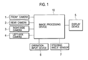
- Fig. 1 is a block diagram showing a schematic configuration of a parking assist system to which the present invention is applied.
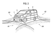
- Fig. 2 is a view explaining positions of four onboard cameras and areas taken by the onboard cameras.
- Fig. 3 is a view showing an example of an image displayed on a display device.
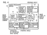
- Fig. 4 is a block diagram showing a functional configuration of an image processing device.
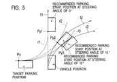
- Fig. 5 is a view explaining an example of a method of calculating a recommended parking start position.
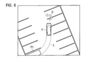
- Fig. 6 is a view showing an example of an image which is displayed on the display device when a vehicle on which the system is mounted reaches the recommended parking start position.
- Fig. 1 is a block diagram showing a schematic configuration of a parking assist system to which the present invention is applied.
- Fig. 2 is a view explaining positions of four onboard cameras and areas taken by the onboard cameras.
- Fig. 3 is a view showing an example of an image displayed on a display device.
- Fig. 4 is
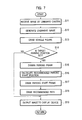
- FIG. 7 is a flowchart showing a flow of a series of steps executed by the image processing device with a predetermined period until the vehicle reaches the recommended parking start position after the parking assist system is activated.
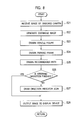
- Fig. 8 is a flowchart showing a flow of a series of steps executed by the image processing device with a predetermined period until the vehicle reaches the target parking position after the vehicle reaches the recommended parking start position.
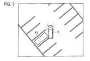
- Fig. 9 is a view explaining a situation where the path of the vehicle is deviated from a recommended path during the parking action, showing an example of an image displayed on the display device at that time.
- Fig. 10 is a view showing an example of an image displayed on the display device when the vehicle stops the parking action.
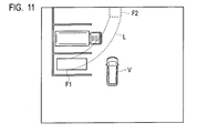
- FIG. 11 is a view showing an example of an image displayed on the display device when there is an obstacle on a path from the recommended parking start position to the target parking position.
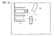
- Fig. 12 is a view showing an example of an image displayed on the display device when there is no obstacle on the path from the recommended parking start position to the target parking position.
- Fig. 1 is a block diagram showing a schematic configuration of a parking assist system to which the present invention is applied.
- the parking assist system of this embodiment displays an overhead image around a vehicle on which the system is mounted and assists a driver of the vehicle in performing a driving operation for parking.
- four onboard cameras of a front camera 1, a rear camera 2, a right-side camera 3, and a left-side camera 4, which are mounted on the vehicle are connected to inputs of an image processing device 10.
- An output of the image processing device 10 is connected to a display device 5 such as a liquid crystal display installed within a compartment of the vehicle.
- the image processing device 10 is connected to an operation input device 6 which receives operation inputs by the driver of the vehicle and is connected to a steering angle sensor 7 which detects steering angle of the vehicle.
- the display device 5 may be provided with a touch-panel type screen so that operations by the driver of the vehicle are inputted through the touch-panel type screen of the display device 5.
- Each of the four onboard cameras of the front, rear, right-side, and left-side cameras 1 to 4 is composed of a wide-angle camera having an angle of view of about 180 degrees, for example. These four cameras are individually mounted at proper places of the vehicle so as to capture images of all the area surrounding the vehicle. Specifically, for example as shown in Fig. 2, the front camera 1 is installed at a front grille of the vehicle or the like and captures an image of an area A3 in front of the vehicle diagonally down towards the ground.
- the rear camera 2 is installed at a roof spoiler of the vehicle or the like and captures an image of an area A2 behind the vehicle diagonally down towards the ground.
- the right-side camera 3 is installed as a right-side mirror of the vehicle or the like and captures an image of an area A3 to the right of the vehicle diagonally down toward the ground.
- the left-side camera 4 is installed at a left-side mirror of the vehicle or the like and captures an image of an area A4 to the left of the vehicle diagonally downward toward the ground.
- the image processing device 10 is composed of an information processing device such as a microcomputer storing a program which processes images.
- the image processing device 10 executes this program with an arithmetic device such as a CPU to generate an image as shown in Fig. 3 to assist the driver of the vehicle in performing the driving operation for parking and display the generated image on the display device 5.
- the image processing device 10 includes an image input section 11, an overhead image generation section 12, a vehicle figure drawing section 13, a parking frame figure drawing section 14, a parking start frame figure drawing section 15, a recommended path drawing section 16, a direction indicator icon drawing section 17, and an image output section 18 as shown in Fig. 4.
- the images captured by the four onboard cameras of the front, rear, right-side, and left-side cameras 1 to 4 are inputted to the image input section 11 of the image processing device 10.
- the image input section 11 stores the image signals from the four onboard cameras in frame memories by units of data constituting a single frame.
- the images which are captured by the onboard cameras and stored in the frame memories are used by the overhead image generation section 12 to generate an overhead image.
- the overhead image generation section 12 performs viewing transformation for the images captured by the four onboard cameras into images of views from virtual viewpoints above the vehicle and joins the transformed images, thus generating an overhead image of an area around the vehicle viewed down from above.
- the generation of the overhead image by the overhead image generation section 12 is repeated at predetermined intervals (for example, at the same intervals as the onboard cameras capture images), and the image signals are stored in frame memories of the image output section 18 and updated as needed.
- a vehicle figure V indicating a current position of the vehicle is drawn by the vehicle figure drawing section 13.
- the vehicle figure drawing section 13 holds a computer graphic image of a vehicle of the same size as that of the vehicle on the overhead image and draws the computer graphic image at the current position of the vehicle on the overhead image (usually at the center of the overhead image) as the vehicle figure V.
- a parking frame figure F1 indicating the target parking position is drawn by the parking frame figure drawing section 14 on the overhead image generated by the overhead image generation section 12, and a parking start frame figure F2 indicating the recommended parking start position later described is drawn by the parking start frame figure drawing section 15.
- a recommended path L from the recommended parking start position to the target parking position at the parking action is then drawn by the recommended path drawing section 16.
- the parking frame figure drawing section 14 recognizes the position which is set as the target parking position on the overhead image and the direction thereof and draws a rectangular frame of the same size as that of the vehicle on the overhead image as the parking frame figure F1.
- the parking start frame figure drawing section 15 based on information of current steering angle of the vehicle detected by the steering angle sensor 7, calculates as the recommended parking start position a position which the vehicle can reach with the steering angle of the vehicle unchanged from the detected current steering angle and the vehicle and from which the vehicle can reach the target parking position set by the driver of the vehicle with a constant steering angle.
- the parking start frame figure drawing section 15 draws a rectangular frame of the same size as that of the vehicle on the overhead image as the parking start frame figure F2.
- Fig. 5 is a view explaining an example of a method by which the parking start frame figure drawing section 15 calculates the recommended parking start position.
- the parking start frame figure drawing section 15 first calculates an predicted trajectory t of the vehicle moving with the current steering angle unchanged based on the information of the current steering angle of the vehicle detected by the steering angle sensor 7.
- t1, t2, and t3 indicate predicted trajectories when the steering angle is 0 degree, 10 degrees right, and 15 degrees right, respectively.
- the parking start frame figure drawing section 15 sets a referential point Px of the target parking position (for example, a point at which a corner of the parking frame figure F1 is located) and calculates an arc (or a line) r which is tangent to the predicted trajectory t of the vehicle moving with the current steering angle unchanged and passes through the referential point Px of the target parking position.
- a referential point Px of the target parking position for example, a point at which a corner of the parking frame figure F1 is located
- an arc (or a line) r which is tangent to the predicted trajectory t of the vehicle moving with the current steering angle unchanged and passes through the referential point Px of the target parking position.
- arcs tangent to the predicted trajectories t1 to t3 are indicated by r1 to r3, respectively.
- the parking start frame figure drawing section 15 calculates a point Py of tangency between the arc (or line) r and predicted trajectory t and calculates the recommended parking start position based on the point Py of tangency as the referential point.
- points of tangency between the arcs r1 and individual predicted trajectories t1 to t3 are indicated by Py1 to Py3, respectively.
- the parking start frame figure drawing section 15 draws, as the parking start frame figure F2, a rectangular frame of the same size as the vehicle on the overhead image at the recommended parking start position on the overhead image calculated by the aforementioned method.
- the recommended parking start position is calculated according to the current steering angle of the vehicle as described above. Accordingly, if the driver of the vehicle operates the steering wheel to change the steering angle, the position of the parking start frame F2 on the overhead image correspondingly changes. For example, in the example shown in Fig.
- the position of the parking start frame figure F2 on the overhead image changes from the position including the point Py1 of tangency as the referential point to the position including the point Py2 of tangency as the referential point.
- the position of the parking start frame figure F2 drawn on the overhead image is changed from the position including the point Py2 of tangency as the referential point to the position including the point Py3 of tangency as the referential point.
- the recommended path drawing section 16 specifies a path through which the vehicle reaches the target parking position set by the driver of the vehicle from the recommended parking start position calculated by the parking start frame figure drawing section 15 with a constant steering angle. The recommended path drawing section 16 then draws lines as the recommended path L along the specified path on the overhead image.
- the image signal of the image which includes the vehicle figure V, parking frame figure F1, parking start frame figure F2, and recommended path L drawn on the overview image generated by the overview image generation section 12 is read out from the frame memory by the image output section 18 as needed and outputted to the display device 5.
- the image shown in Fig. 3 is always updated and displayed as a moving image.
- the driver of the vehicle sees the image displayed on the display device 5 and can recognize the recommended parking start position, from which the vehicle can reach the target parking position with a constant steering angle, or a position at which the driver should start the parking action to reach the target parking position without performing the steering operation during the parking action.
- the driver moves the vehicle to the recommended parking start position and then starts the parking action, thus extremely facilitating the driving operation for parking.
- the parking start frame figure F2 indicating the recommended parking start position is especially displayed with the position on the overhead image varied with changes in steering angle due to the steering operation by the driver of the vehicle. Accordingly, the driver of the vehicle operates the steering wheel while checking the condition around the vehicle displayed in the overhead image to move the parking start frame figure F2 to an optimal position, thus easily parking the vehicle from the optical position.
- the parking start frame F2 on the overhead image is for the purpose of causing the driver of the vehicle to recognize the recommended parking start position. Accordingly, the parking start frame F2 does not need to be displayed after the vehicle reaches the recommended parking start position.
- the driver needs to turn again the steering wheel to the steering angle allowing the vehicle to move from the recommended parking start position to the target parking position along the recommended path L. It is therefore desirable to cause the driver of the vehicle to recognize the steering direction.
- the image processing device 10 is configured to judge whether the vehicle reaches the recommended parking start position by judging whether the position of the vehicle matches the recommended parking start position on the overhead image.
- the drawing of the parking start frame figure F2 by the parking start frame figure drawing section 15 is terminated, and a direction indicator icon D, which indicates the steering direction allowing the vehicle to reach the target parking position from the recommended parking start position, is drawn on the overhead image by the direction indicator icon drawing section 17. Accordingly, when the vehicle reaches the recommended parking start position, for example, an image shown in Fig. 6 is displayed on the display device 5.
- the direction indicator icon drawing section 17 calculates an amount of necessary steering operation and the direction of the same based on a relationship between the current steering angle of the vehicle detected by the steering angle sensor 7 and the steering angle allowing the vehicle to move from the recommended parking start position to the target parking position along the recommended path L.
- the direction indicator icon drawing section 17 draws an arrow figure corresponding to the calculated direction of the steering operation near the vehicle figure V on the overhead image as the direction indicator icon D.
- the direction indicator icon drawing section 17 monitors the steering angle of the vehicle detected by the steering angle sensor 7 while drawing the direction indicator icon D on the overhead image.
- the direction indicator icon drawing section 17 finishes drawing the direction indicator icon D when judging that the current steering angle of the vehicle is equal to the steering angle allowing the vehicle to move from the recommended parking start position to the target parking position along the recommended path L.
- Fig. 7 is a flowchart showing a flow of a series of steps executed with a predetermined period (for example, a capture period of the onboard cameras) by the image processing device 10 until the vehicle reaches the recommended parking start position after the parking assist system is started upon a switching operation by the driver of the vehicle, for example.
- Fig. 8 is a flowchart showing a flow of a series of steps executed with a predetermined period (for example, the capture period of the onboard cameras) by the image processing device 10 until the vehicle reaches the target parking position after the vehicle reaches the recommended parking start position.
- step S11 the images captured by the four onboard cameras of the front, rear, right-side, and left-side cameras 1 to 4 are inputted into the image input section 11 of the image processing device 10 and stored in the frame memories in step S11.
- step S12 using these images captured by the four onboard cameras, the overhead image of a downward view around the vehicle is generated and stored in the frame memory of the image output section 18 by the overhead image generation section 12.
- step S13 at the current position of the vehicle on the overhead image generated in the step S12, the vehicle figure V is drawn by the vehicle figure drawing section 13.
- step S14 it is judged whether the target parking position is set by the driver of the vehicle.
- the process proceeds to step S19, and the image including only the vehicle figure V drawn on the overhead image around the vehicle is outputted to the display device 5 by the image output section 18 and is displayed on the display device 5.
- step S15 the parking frame figure F1 is drawn by the parking frame figure drawing section 14 at the target parking position on the overhead image generated in the step S12.
- step S16 the recommended parking start position, from which the vehicle can reach the target parking position with a constant steering angle, is calculated by the parking start frame figure drawing section 15.
- step S17 the parking start frame F2 is drawn at the recommended parking start position on the overhead image generated in the step S12.
- step S18 the recommended path L of the vehicle at the parking action from the recommended parking start position to the target parking position is drawn on the overhead image generated in the step S12 by the recommended path drawing section 16.
- step S19 the image including the vehicle figure V, parking frame figure F1, parking start frame figure F2, and recommended path L drawn on the overhead image around the vehicle is outputted to the display device 5 by the image output section 18 and displayed on the display device 5.
- step S21 the images captured by the four onboard cameras of the front, rear, right-side, and left-side cameras 1 to 4 are inputted into the image input section 11.
- step S22 the overhead image is generated from these images captured by the four onboard cameras by the overhead image generation section 12.
- step S23 the vehicle figure V is drawn by the vehicle figure drawing section 13 on the overhead image generated in the step S22, and in step S24, the parking frame figure F1 is drawn by the parking frame drawing section 14 on the overhead image generated in the step S22.
- step S25 the recommended path L to the target parking position is drawn by the recommended path drawing section 16 on the overhead image.
- step S26 it is judged by the direction indicator icon drawing section 17 whether the steering operation to set the steering angle of the vehicle to the steering angle allowing the vehicle to reach the target parking position along the recommended path L is finished.
- step S27 the direction indicator icon D is further drawn on the overhead image drawn in the step S22.
- step S28 the image including the vehicle figure V, parking frame figure F1, recommended path L, and direction indicator icon D (when the steering operation is not finished yet) drawn on the overhead image around the vehicle is outputted by the image output section 18 to the display device 5 and is displayed on the display device 5.
- the parking assist system of this embodiment calculates the recommended parking start position, which the vehicle can reach with the steering angle of the vehicle unchanged and from which the vehicle can reach the target parking position with a constant steering angle.
- the parking assist system displays on the display device 5 the parking start frame figure F2, which indicates the recommended parking start position and is drawn on the overhead image around the vehicle in addition to the vehicle figure V indicating the current position of the vehicle and the parking frame figure F1 indicating the target parking position.
- the parking assist system it is therefore possible to allow the driver of the vehicle to recognize the position from which the driver should start the parking action in order to easily reach the target parking position.
- the parking assist system of this embodiment can effectively assist especially inexperienced drivers in performing the driving operation for parking.
- the recommended path L through which the vehicle can reach the recommended parking start position to the target parking position with a constant steering angle, is drawn on the overhead image around the vehicle. Accordingly, it is possible to allow the driver to recognize the path of the vehicle for the actual parking action. For example, when the recommended path L is overlapped with an obstacle or the like displayed on the overhead image, the parking assist system can prompt the driver of the vehicle to take measures such as changing the recommended parking start position.
- the direction indicator icon D indicating the steering direction allowing the vehicle to reach the target parking position from the recommended parking start position is further drawn on the overview image. Accordingly, it is possible to allow the driver of the vehicle to recognize the steering operation which is required at the recommended parking start position, thus providing more effective assistance for the driving operation at parking.
- the driver of the vehicle is caused to recognize the steering operation required at the recommended parking start position by drawing the direction indicator icon D on the overhead image. However, it is effective to display a message such as "Turn the steering wheel to the right" on the display device 5 or speak such a message instead of or in addition to the direction indicator icon D.
- calculation of the recommended parking start position and drawing of the parking start frame figure F2 are terminated when the vehicle reaches the recommended parking start position on the premise that the vehicle which has reached the recommended parking start position reaches the target parking position along the recommended path L.
- the driver may perform a steering operation by an accidental cause or unconsciously perform a steering operation. Accordingly, it could be that the path of the vehicle is deviated from the recommended path L and does not accurately reach the target parking position. In such a case, it is necessary to once stop the parking action and start another parking action to cause the vehicle to accurately reach another target parking position.
- the configuration of the parking assist system of this embodiment is the same as that of the first embodiment shown in Fig. 4.
- the basic part of the processes implemented by the individual functional constitutions of the image processing system 10 is the same as that of the first embodiment. In this embodiment, for example, it is judged based on stop of the vehicle, gear change, or the like before the vehicle reaches the target parking position whether the parking action is stopped.
- the parking start frame figure drawing section 15 of the image processing device 10 starts again the calculation of the recommended parking start position and the drawing of the parking start frame figure F2.
- the parking start frame figure drawing section 15 of the image processing device 10 calculates the position which the vehicle can reach with the current steering angle unchanged and from which the vehicle can reach the already set target parking position with a constant steering angle as a new recommended parking start position based on information on a current steering angle of the vehicle detected by the steering angle sensor 7.
- the parking start frame figure drawing section 15 then draws the parking start frame figure F2 at a position corresponding to the new parking start position on the overhead image generated by the overhead image generation section 12.
- the concrete method of calculating the new recommended parking start position is the same as that of the first embodiment.
- the recommended path drawing section 16 draws on the overhead image a new recommended path L through which the vehicle can reach the target parking position from the new recommended parking start position with a constant steering angle.
- the image including the vehicle figure V, parking frame figure F1, parking start frame figure F2, and recommended path L drawn on the overhead image is displayed again as shown in Fig. 10, for example.
- the driver of the vehicle moves the vehicle to the recommended parking start position while seeing the displayed image and then starts the parking action again. Accordingly, the driver of the vehicle can extremely easily perform the driving operation for parking.
- the parking start frame figure drawing section 15 of the image processing device 10 starts again the calculation of the new recommended parking start position and the drawing of the parking start frame figure F2. Accordingly, at the parking action started again, it is also possible to allow the driver of the vehicle to recognize from which position to start the parking action in order to easily reach the target parking position, thus providing more effective assistance to the driving operation for parking.
- the parking start frame figure F2 drawn on the overhead image varies depending on the presence of an obstacle on a path from the recommended parking start position to the target parking position.
- the configuration of the parking assist system of this embodiment is the same as that of the first embodiment shown in Fig. 4, and the basic part of the processes implemented by the individual functional constitutions of the image processing device 10 is also the same as that of the first embodiment.
- the parking start frame figure drawing section 15 of the image processing device 10 judges whether there is an obstacle on the path from the calculated recommended parking start position to the target parking position.
- the parking start frame figure drawing section 15 draws the parking start frame figure F2 in different forms depending on the presence or absence of an obstacle on the path from the recommended parking start position to the target parking position.
- the presence of an obstacle on the path from the recommended parking start position to the target parking position can be judged based on the positional relationship between the obstacle and the path from the recommended parking start position to the target parking position by, for example, when the vehicle includes an obstacle sensor such as an ultrasonic sensor, specifying the position of the obstacle based on a sensor signal of the obstacle sensor.
- the presence of an obstacle can be also judged based on the positional relationship between the obstacle and the path from the recommended parking start position to the target parking position by analyzing the images captured by the onboard cameras and specifying the position of the obstacle.
- the type of lines of the frame of the parking start frame figure F2 can be varied.
- the parking start frame figure F2 is drawn as a dashed frame as shown in Fig. 11, and when there is no obstacle on the path from the recommended parking start position to the target parking position, the parking start frame figure F2 is drawn as a solid frame as shown in Fig. 12.
- thickness of the lines of the parking start frame figure F2 can be varied.
- the parking start frame figure F2 When there is an obstacle on the path from the recommended parking start position to the target parking position, the parking start frame figure F2 is drawn with thin lines, and when there is no obstacle on the path from the recommended parking start position to the target parking position, the parking start frame figure F2 is drawn with thick lines. In addition, it is also effective that color of the parking start frame figure 2 is varied depending on the presence or absence of an obstacle on the path between the recommended parking start position and the target parking position.
- the parking start frame figure drawing section 15 of the image processing device 10 judges whether there is an obstacle on the path from the calculated recommended parking start position to the target parking position and draws the parking start frame figure F2 on the overhead image in different forms depending on the presence or absence of an obstacle. It is therefore possible to allow the driver of the vehicle to easily recognize whether to start the parking action from the recommended parking start position corresponding to the current steering angle.
- the parking assist system of this embodiment can prompt the driver of the vehicle to perform a steering operation to change the recommended parking start position to an optimal position.
- the present invention is applicable to a technique assisting a driver in performing driving operation at parking a vehicle.
Landscapes
- Engineering & Computer Science (AREA)
- Chemical & Material Sciences (AREA)
- Combustion & Propulsion (AREA)
- Transportation (AREA)
- Mechanical Engineering (AREA)
- Traffic Control Systems (AREA)
- Closed-Circuit Television Systems (AREA)
- Image Processing (AREA)
- Image Analysis (AREA)
- Steering Control In Accordance With Driving Conditions (AREA)
Priority Applications (3)
| Application Number | Priority Date | Filing Date | Title |
|---|---|---|---|
| CN2008801233637A CN101909972B (zh) | 2007-12-26 | 2008-11-17 | 车辆用停车辅助系统和方法 |
| EP08864040.4A EP2265482B1 (en) | 2007-12-26 | 2008-11-17 | Vehicle parking assist system and method |
| US12/810,258 US8498770B2 (en) | 2007-12-26 | 2008-11-17 | Vehicle parking assist system and method |
Applications Claiming Priority (2)
| Application Number | Priority Date | Filing Date | Title |
|---|---|---|---|
| JP2007-334018 | 2007-12-26 | ||
| JP2007334018A JP4900232B2 (ja) | 2007-12-26 | 2007-12-26 | 車両用駐車支援装置および映像表示方法 |
Publications (1)
| Publication Number | Publication Date |
|---|---|
| WO2009081519A1 true WO2009081519A1 (en) | 2009-07-02 |
Family
ID=40342441
Family Applications (1)
| Application Number | Title | Priority Date | Filing Date |
|---|---|---|---|
| PCT/JP2008/003341 WO2009081519A1 (en) | 2007-12-26 | 2008-11-17 | Vehicle parking assist system and method |
Country Status (5)
| Country | Link |
|---|---|
| US (1) | US8498770B2 (zh) |
| EP (1) | EP2265482B1 (zh) |
| JP (1) | JP4900232B2 (zh) |
| CN (2) | CN102923192A (zh) |
| WO (1) | WO2009081519A1 (zh) |
Cited By (7)
| Publication number | Priority date | Publication date | Assignee | Title |
|---|---|---|---|---|
| EP2345571A1 (de) * | 2010-01-18 | 2011-07-20 | Robert Bosch GmbH | Verfahren zur Unterstützung eines Fahrers eines Kraftfahrzeugs |
| EP2147826A3 (en) * | 2008-07-25 | 2011-12-14 | Nissan Motor Co., Ltd. | Parking assistance apparatus and parking assistance method |
| US20130169792A1 (en) * | 2010-08-12 | 2013-07-04 | Valeo Schalter Und Sensoren Gmbh | Method for assisting in a parking operation for a motor vehicle, driver assistance system and a motor vehicle |
| US8498770B2 (en) | 2007-12-26 | 2013-07-30 | Nissan Motor Co., Ltd. | Vehicle parking assist system and method |
| EP2707266A4 (en) * | 2011-05-09 | 2015-12-23 | Lg Innotek Co Ltd | PARKING CAMERA SYSTEM AND ITS CONTROL METHOD |
| US10179608B2 (en) | 2016-08-31 | 2019-01-15 | Aisin Seiki Kabushiki Kaisha | Parking assist device |
| US11260851B2 (en) | 2019-08-28 | 2022-03-01 | Nissan North America, Inc. | Method of positioning vehicle during parking operation |
Families Citing this family (37)
| Publication number | Priority date | Publication date | Assignee | Title |
|---|---|---|---|---|
| GB2447672B (en) | 2007-03-21 | 2011-12-14 | Ford Global Tech Llc | Vehicle manoeuvring aids |
| JP4900326B2 (ja) * | 2008-06-10 | 2012-03-21 | 日産自動車株式会社 | 駐車支援装置及び駐車支援方法 |
| DE102009003298A1 (de) * | 2009-05-20 | 2010-11-25 | Robert Bosch Gmbh | Vorrichtung und Verfahren zum unterstützten Einparken eines Fahrzeugs |
| DE102010002409A1 (de) * | 2010-02-26 | 2011-09-01 | Robert Bosch Gmbh | Verfahren zur Unterstützung eines Einparkvorgangs |
| MX336660B (es) * | 2010-06-11 | 2016-01-27 | Nissan Motor | Aparato y metodo de asistencia de aparcamiento. |
| JP5099195B2 (ja) * | 2010-09-24 | 2012-12-12 | 株式会社デンソー | 車両用の後退駐車支援装置および後退駐車支援装置用のプログラム |
| EP2481637B1 (en) | 2011-01-28 | 2014-05-21 | Nxp B.V. | Parking Assistance System and Method |
| US9854209B2 (en) | 2011-04-19 | 2017-12-26 | Ford Global Technologies, Llc | Display system utilizing vehicle and trailer dynamics |
| US9926008B2 (en) | 2011-04-19 | 2018-03-27 | Ford Global Technologies, Llc | Trailer backup assist system with waypoint selection |
| US9723274B2 (en) | 2011-04-19 | 2017-08-01 | Ford Global Technologies, Llc | System and method for adjusting an image capture setting |
| KR101327736B1 (ko) * | 2011-12-23 | 2013-11-11 | 현대자동차주식회사 | Avm탑뷰 기반 주차지원 시스템 |
| US9598836B2 (en) | 2012-03-29 | 2017-03-21 | Harnischfeger Technologies, Inc. | Overhead view system for a shovel |
| US8862321B2 (en) * | 2012-08-15 | 2014-10-14 | GM Global Technology Operations LLC | Directing vehicle into feasible region for autonomous and semi-autonomous parking |
| US9378425B2 (en) * | 2012-11-27 | 2016-06-28 | Clarion Co., Ltd. | On-vehicle image processing device |
| EP2928182B1 (en) * | 2012-11-27 | 2019-07-17 | Clarion Co., Ltd. | Onboard image processing system |
| DE102014202324A1 (de) * | 2014-02-10 | 2015-08-13 | Conti Temic Microelectronic Gmbh | Verfahren und Vorrichtung zum sicheren Parken eines Fahrzeugs |
| US9751558B2 (en) | 2015-03-25 | 2017-09-05 | Ford Global Technologies, Llc | Handwheel obstruction detection and inertia compensation |
| US9731765B2 (en) | 2015-08-12 | 2017-08-15 | Hyundai Motor Company | Parking assist apparatus and method |
| US9981656B2 (en) | 2015-10-13 | 2018-05-29 | Ford Global Technologies, Llc | Vehicle parking assist system |
| US9836060B2 (en) | 2015-10-28 | 2017-12-05 | Ford Global Technologies, Llc | Trailer backup assist system with target management |
| US10328933B2 (en) | 2015-10-29 | 2019-06-25 | Ford Global Technologies, Llc | Cognitive reverse speed limiting |
| US10906530B2 (en) * | 2015-11-10 | 2021-02-02 | Hyundai Motor Company | Automatic parking system and automatic parking method |
| US10683035B2 (en) | 2015-12-08 | 2020-06-16 | Panasonic Intellectual Property Management Co., Ltd. | Parking assistance device, parking assistance method, and non-transitory computer readable medium |
| JP6745456B2 (ja) | 2015-12-08 | 2020-08-26 | パナソニックIpマネジメント株式会社 | 駐車支援装置、駐車支援方法及び駐車支援プログラム |
| US9895945B2 (en) | 2015-12-08 | 2018-02-20 | Ford Global Technologies, Llc | Trailer backup assist system with hitch assist |
| EP3514031B1 (en) * | 2016-09-13 | 2020-11-18 | Nissan Motor Co., Ltd. | Parking assist method and device |
| US9829883B1 (en) | 2016-10-17 | 2017-11-28 | Ford Global Technologies, Llc | Trailer backup assist system having remote control and user sight management |
| US10369988B2 (en) * | 2017-01-13 | 2019-08-06 | Ford Global Technologies, Llc | Autonomous parking of vehicles inperpendicular parking spots |
| CN109109855B (zh) * | 2017-06-22 | 2021-03-23 | 蔚来(安徽)控股有限公司 | 用于使车辆自动驶入车位的方法和装置 |
| US10427716B2 (en) | 2017-09-12 | 2019-10-01 | Ford Global Technologies, Llc | Hitch assist system and method |
| CN107792179B (zh) * | 2017-09-27 | 2019-08-23 | 浙江零跑科技有限公司 | 一种基于车载环视系统的泊车引导方法 |
| US10899385B2 (en) * | 2017-10-23 | 2021-01-26 | Magna Electronics Inc. | Vehicle and trailer backup guidance system |
| JP6917330B2 (ja) * | 2018-03-28 | 2021-08-11 | 日立Astemo株式会社 | 駐車支援装置 |
| US10891866B2 (en) * | 2018-11-13 | 2021-01-12 | Hall Labs Llc | Parking assist apparatus |
| US11745728B2 (en) * | 2019-04-23 | 2023-09-05 | Mitsubishi Electric Corporation | Parking assistance device and parking assistance method |
| CN111369823B (zh) * | 2020-02-20 | 2021-07-20 | 江苏大学 | 一种辅助泊车装置及其辅助泊车方法 |
| JP2021142839A (ja) * | 2020-03-11 | 2021-09-24 | 本田技研工業株式会社 | 車両及びその制御装置 |
Citations (5)
| Publication number | Priority date | Publication date | Assignee | Title |
|---|---|---|---|---|
| JP2005239048A (ja) | 2004-02-27 | 2005-09-08 | Denso Corp | 駐車支援システム |
| WO2005120932A1 (de) | 2004-06-05 | 2005-12-22 | Robert Bosch Gmbh | Verfahren und vorrichtung zum unterstützten einparken eines kraftfahrzeuges |
| WO2006100892A1 (en) | 2005-03-22 | 2006-09-28 | Kabushiki Kaisha Toyota Jidoshokki | Parking assistance apparatus |
| WO2007015446A1 (ja) | 2005-08-02 | 2007-02-08 | Nissan Motor Co., Ltd. | 車両周囲監視装置及び車両周囲監視方法 |
| EP1862376A2 (de) * | 2006-06-03 | 2007-12-05 | Bayerische Motoren Werke Aktiengesellschaft | Verfahren zur Steuerung eines Einparkvorgangs |
Family Cites Families (25)
| Publication number | Priority date | Publication date | Assignee | Title |
|---|---|---|---|---|
| EP1038734B1 (en) | 1998-10-08 | 2019-05-15 | Panasonic Intellectual Property Corporation of America | Driving assisting device and recording medium |
| US7161616B1 (en) * | 1999-04-16 | 2007-01-09 | Matsushita Electric Industrial Co., Ltd. | Image processing device and monitoring system |
| US6411867B1 (en) | 1999-10-27 | 2002-06-25 | Fujitsu Ten Limited | Vehicle driving support system, and steering angle detection device |
| JP4615766B2 (ja) * | 2000-12-15 | 2011-01-19 | 本田技研工業株式会社 | 駐車支援装置 |
| JP2004025942A (ja) | 2002-06-21 | 2004-01-29 | Equos Research Co Ltd | 駐車操作支援装置 |
| DE10250021A1 (de) * | 2002-10-25 | 2004-05-13 | Donnelly Hohe Gmbh & Co. Kg | Verfahren zum Betrieb eines Darstellungssystems in einem Fahrzeug zum Auffinden eines Parkplatzes |
| JP4058369B2 (ja) * | 2003-03-27 | 2008-03-05 | トヨタ自動車株式会社 | 駐車支援装置 |
| CN100400357C (zh) * | 2004-04-19 | 2008-07-09 | 株式会社丰田自动织机 | 停车辅助设备 |
| JP4466200B2 (ja) * | 2004-04-19 | 2010-05-26 | 株式会社豊田自動織機 | 駐車支援装置 |
| JP4654870B2 (ja) * | 2005-04-06 | 2011-03-23 | 日産自動車株式会社 | 駐車支援装置及び駐車支援方法 |
| JP2006341641A (ja) * | 2005-06-07 | 2006-12-21 | Nissan Motor Co Ltd | 映像表示装置及び映像表示方法 |
| JP2007099261A (ja) * | 2005-09-12 | 2007-04-19 | Aisin Aw Co Ltd | 駐車支援方法及び駐車支援装置 |
| JP2007118922A (ja) * | 2005-09-27 | 2007-05-17 | Clarion Co Ltd | 車両後退運転支援装置 |
| JP4910425B2 (ja) * | 2006-03-01 | 2012-04-04 | 日産自動車株式会社 | 駐車支援装置及び駐車支援方法 |
| JP5309442B2 (ja) * | 2006-05-29 | 2013-10-09 | アイシン・エィ・ダブリュ株式会社 | 駐車支援方法及び駐車支援装置 |
| JP4818816B2 (ja) * | 2006-06-05 | 2011-11-16 | 富士通株式会社 | 駐車支援プログラム及び駐車支援装置 |
| JP5087885B2 (ja) * | 2006-08-16 | 2012-12-05 | 日産自動車株式会社 | 駐車支援装置、及び駐車支援方法 |
| KR101143176B1 (ko) * | 2006-09-14 | 2012-05-08 | 주식회사 만도 | 조감도를 이용한 주차구획 인식 방법, 장치 및 그를 이용한주차 보조 시스템 |
| JP5115782B2 (ja) * | 2006-11-07 | 2013-01-09 | アイシン精機株式会社 | 駐車支援装置 |
| JP5088074B2 (ja) * | 2007-10-01 | 2012-12-05 | 日産自動車株式会社 | 駐車支援装置及び方法 |
| US8694195B2 (en) * | 2007-12-04 | 2014-04-08 | Volkswagen Ag | Motor vehicle having a wheel-view camera and method for controlling a wheel-view camera system |
| JP4992696B2 (ja) * | 2007-12-14 | 2012-08-08 | 日産自動車株式会社 | 駐車支援装置及び方法 |
| JP4900232B2 (ja) | 2007-12-26 | 2012-03-21 | 日産自動車株式会社 | 車両用駐車支援装置および映像表示方法 |
| JP4900326B2 (ja) * | 2008-06-10 | 2012-03-21 | 日産自動車株式会社 | 駐車支援装置及び駐車支援方法 |
| JP4661917B2 (ja) * | 2008-07-25 | 2011-03-30 | 日産自動車株式会社 | 駐車支援装置および駐車支援方法 |
-
2007
- 2007-12-26 JP JP2007334018A patent/JP4900232B2/ja active Active
-
2008
- 2008-11-17 CN CN2012104015223A patent/CN102923192A/zh active Pending
- 2008-11-17 EP EP08864040.4A patent/EP2265482B1/en active Active
- 2008-11-17 US US12/810,258 patent/US8498770B2/en active Active
- 2008-11-17 CN CN2008801233637A patent/CN101909972B/zh active Active
- 2008-11-17 WO PCT/JP2008/003341 patent/WO2009081519A1/en active Application Filing
Patent Citations (5)
| Publication number | Priority date | Publication date | Assignee | Title |
|---|---|---|---|---|
| JP2005239048A (ja) | 2004-02-27 | 2005-09-08 | Denso Corp | 駐車支援システム |
| WO2005120932A1 (de) | 2004-06-05 | 2005-12-22 | Robert Bosch Gmbh | Verfahren und vorrichtung zum unterstützten einparken eines kraftfahrzeuges |
| WO2006100892A1 (en) | 2005-03-22 | 2006-09-28 | Kabushiki Kaisha Toyota Jidoshokki | Parking assistance apparatus |
| WO2007015446A1 (ja) | 2005-08-02 | 2007-02-08 | Nissan Motor Co., Ltd. | 車両周囲監視装置及び車両周囲監視方法 |
| EP1862376A2 (de) * | 2006-06-03 | 2007-12-05 | Bayerische Motoren Werke Aktiengesellschaft | Verfahren zur Steuerung eines Einparkvorgangs |
Cited By (13)
| Publication number | Priority date | Publication date | Assignee | Title |
|---|---|---|---|---|
| US8498770B2 (en) | 2007-12-26 | 2013-07-30 | Nissan Motor Co., Ltd. | Vehicle parking assist system and method |
| EP2147826A3 (en) * | 2008-07-25 | 2011-12-14 | Nissan Motor Co., Ltd. | Parking assistance apparatus and parking assistance method |
| US8319614B2 (en) | 2008-07-25 | 2012-11-27 | Nissan Motor Co., Ltd. | Parking assistance apparatus and parking assistance method |
| EP2345571A1 (de) * | 2010-01-18 | 2011-07-20 | Robert Bosch GmbH | Verfahren zur Unterstützung eines Fahrers eines Kraftfahrzeugs |
| US20130169792A1 (en) * | 2010-08-12 | 2013-07-04 | Valeo Schalter Und Sensoren Gmbh | Method for assisting in a parking operation for a motor vehicle, driver assistance system and a motor vehicle |
| US10558221B2 (en) * | 2010-08-12 | 2020-02-11 | Valeo Schalter Und Sensoren Gmbh | Method for assisting in a parking operation for a motor vehicle, driver assistance system and a motor vehicle |
| US9519832B2 (en) | 2011-05-09 | 2016-12-13 | Lg Innotek Co., Ltd. | Parking camera system and method of driving the same |
| US10074018B2 (en) | 2011-05-09 | 2018-09-11 | Lg Innotek Co., Ltd. | Parking camera system and method of driving the same |
| EP3560782A1 (en) | 2011-05-09 | 2019-10-30 | Lg Innotek Co. Ltd | Parking camera system and method of driving the same |
| EP2707266A4 (en) * | 2011-05-09 | 2015-12-23 | Lg Innotek Co Ltd | PARKING CAMERA SYSTEM AND ITS CONTROL METHOD |
| US10179608B2 (en) | 2016-08-31 | 2019-01-15 | Aisin Seiki Kabushiki Kaisha | Parking assist device |
| EP3290301B1 (en) * | 2016-08-31 | 2021-06-16 | Aisin Seiki Kabushiki Kaisha | Parking assist device |
| US11260851B2 (en) | 2019-08-28 | 2022-03-01 | Nissan North America, Inc. | Method of positioning vehicle during parking operation |
Also Published As
| Publication number | Publication date |
|---|---|
| CN102923192A (zh) | 2013-02-13 |
| US20100274474A1 (en) | 2010-10-28 |
| US8498770B2 (en) | 2013-07-30 |
| JP4900232B2 (ja) | 2012-03-21 |
| CN101909972A (zh) | 2010-12-08 |
| EP2265482A1 (en) | 2010-12-29 |
| EP2265482B1 (en) | 2016-02-10 |
| JP2009154654A (ja) | 2009-07-16 |
| CN101909972B (zh) | 2013-04-17 |
Similar Documents
| Publication | Publication Date | Title |
|---|---|---|
| WO2009081519A1 (en) | Vehicle parking assist system and method | |
| JP5003946B2 (ja) | 駐車支援装置 | |
| EP2683164B1 (en) | Driving assistance device and towing vehicle | |
| KR101375944B1 (ko) | 주차 지원 장치 | |
| US8941737B2 (en) | Image generating apparatus and image display system | |
| US10268905B2 (en) | Parking assistance apparatus | |
| US8937558B2 (en) | Image generating apparatus and image display system | |
| JP4853712B2 (ja) | 駐車支援装置 | |
| EP2145799B1 (en) | Parking assisting system | |
| US8319614B2 (en) | Parking assistance apparatus and parking assistance method | |
| EP2281722B1 (en) | Parking support device | |
| US20110001614A1 (en) | Rear Camera Backup Assistance With Touchscreen Display | |
| US20030030724A1 (en) | Park-assisting apparatus | |
| JP5182137B2 (ja) | 車両周辺表示装置 | |
| JP2005186648A (ja) | 車両用周囲視認装置および表示制御装置 | |
| US20220144169A1 (en) | Rear-view camera system for a trailer hitch system | |
| JP2010006129A (ja) | 車両後方情報表示装置および車両後方情報表示方法 | |
| JP2012030796A (ja) | 車両用駐車支援装置および映像表示方法 | |
| JP2017143482A (ja) | 車両用画像表示装置 | |
| JP2001180402A (ja) | 駐車時の操舵支援装置 | |
| KR102005551B1 (ko) | 주차 보조 시스템 | |
| JP2014226966A (ja) | 車両の駐車操作支援用映像表示装置 | |
| JP2012237725A (ja) | 車両用表示装置 | |
| KR20050100146A (ko) | 차량의 예상 이동 궤적 표시 장치 | |
| JP2006298217A (ja) | 車両周辺監視装置 |
Legal Events
| Date | Code | Title | Description |
|---|---|---|---|
| WWE | Wipo information: entry into national phase |
Ref document number: 200880123363.7 Country of ref document: CN |
|
| 121 | Ep: the epo has been informed by wipo that ep was designated in this application |
Ref document number: 08864040 Country of ref document: EP Kind code of ref document: A1 |
|
| WWE | Wipo information: entry into national phase |
Ref document number: 2008864040 Country of ref document: EP |
|
| WWE | Wipo information: entry into national phase |
Ref document number: 12810258 Country of ref document: US |
|
| NENP | Non-entry into the national phase |
Ref country code: DE |