明 細 書 Specification
光記録媒体及び光記録媒体の光記録方法 Optical recording medium and optical recording method for optical recording medium
技術分野 Technical field
[0001] 本発明は光記録媒体等に関し、より詳しくは、色素を含有する記録層を有する光記 録媒体等に関する。 背景技術 The present invention relates to an optical recording medium and the like, and more particularly to an optical recording medium and the like having a recording layer containing a dye. Background art
[0002] 近年、超高密度の記録が可能となる青色レーザの開発は急速に進んでおり、それ に対応した追記型の光記録媒体の開発が行なわれている。中でも、比較的安価のコ ストで効率的な生産が可能となる色素塗布型の追記型媒体の開発が強く望まれてい る。従来の色素塗布型追記型の光記録媒体では、色素を主成分とする有機化合物 力 なる記録層にレーザ光を照射し、有機化合物の分解'変質による光学的 (屈折率 •吸収率)変化を主に生じさせることで記録ピットを形成させて 、る。記録ピット部は、 光学的変化のみならず、通常は、記録層体積変化による変形、発熱による基板と色 素の混合部形成、基板変形 (主として基板膨張による盛り上がり)等を伴う(特許文献 1、特許文献 2、特許文献 3、特許文献 4参照)。 [0002] In recent years, blue lasers capable of ultra-high density recording have been rapidly developed, and write-once type optical recording media corresponding thereto have been developed. In particular, development of a dye-coated write-once medium that enables efficient production at a relatively low cost is strongly desired. Conventional dye-coated write-once optical recording media irradiate a recording layer consisting of a dye-containing organic compound with a laser beam to cause optical (refractive index / absorption) changes due to decomposition and alteration of the organic compound. Mainly generated to form recording pits. The recording pit portion is not only optically changed, but usually accompanied by deformation due to volume change of the recording layer, formation of a mixed portion of the substrate and dye due to heat generation, substrate deformation (primarily rising due to substrate expansion), etc. (Patent Document 1, (See Patent Document 2, Patent Document 3, and Patent Document 4).
[0003] 記録層に用いられる有機化合物の記録 ·再生に用いるレーザ波長に対する光学的 挙動、分解'昇華及びこれに伴う発熱等の熱的挙動が良好な記録ピットを形成させる ための重要な要素となっている。したがって、記録層に用いる有機化合物は、光学的 性質、分解挙動の適切な材料を選択する必要がある。 [0003] It is an important factor for forming recording pits with good thermal behavior such as optical behavior with respect to the laser wavelength used for recording and reproduction of the organic compound used in the recording layer, decomposition 'sublimation, and heat generation associated therewith. It has become. Therefore, it is necessary to select an organic compound used for the recording layer that is suitable for optical properties and decomposition behavior.
[0004] そもそも、従来型の追記型媒体、特に、 CD—I^^DVD—i e«、 Al、 Ag、 Au等 の反射膜を基板上にあらかじめ形成した凹上ピットに被覆してなる再生専用の記録 媒体 (ROM媒体)との再生互換を維持することを目的とし、概ね 60%以上の反射率 と、同様に、概ね 60%を超える高変調度を実現することを目的としている。先ず、未 記録状態で高反射率を得るために、記録層の光学的性質が規定される。通常は、未 記録状態で屈折率 nが約 2以上、吸収係数が 0. 01〜0. 3程度の値が要求される。( 特許文献 5、特許文献 6参照) [0004] In the first place, conventional write-once media, in particular CD-I ^^ DVD-ie «, Al, Ag, Au, etc. are coated on the concave pits formed in advance on the substrate for reproduction only. The purpose is to maintain playback compatibility with other recording media (ROM media), and to achieve a reflectivity of approximately 60% or higher and, similarly, a high degree of modulation exceeding 60%. First, in order to obtain a high reflectance in an unrecorded state, the optical properties of the recording layer are defined. Normally, a value of about 2 or more and an absorption coefficient of about 0.01 to 0.3 is required in an unrecorded state. (See Patent Document 5 and Patent Document 6)
[0005] 色素を主成分とする記録層では、記録による力かる光学的性質の変化だけでは、 6
0%以上もの高変調度をえることが困難である。即ち、屈折率 nと吸収率 kの変化量が 有機物である色素では限りがあるので、平面状態での反射率変化には限りがある。 [0005] In a recording layer containing a dye as a main component, a change in optical properties due to recording alone is not sufficient. It is difficult to obtain a high modulation degree of 0% or more. That is, since the amount of change in the refractive index n and the absorptance k is limited for dyes that are organic matter, the change in reflectance in a planar state is limited.
[0006] そこで、記録ピット部と未記録部の反射光の位相差による量部分力 の反射光の干 渉効果を用いて、記録ピット部分での反射率変化 (反射率低下)を見かけ上大きくす る方法が利用されている。つまり、 ROM媒体のような位相差ピットと同様の原理が用 いられており、屈折率変化が無機物より小さい有機物記録層の場合、むしろ、位相差 による反射率変化が主として用いることが有利であることが報告されている(特許文献 7参照)。また、上記の記録原理を総合的に考慮した検討が行われている (非特許文 献 1参照)。 [0006] Therefore, apparently a change in reflectivity (decrease in reflectivity) in the recorded pit portion is apparently increased by using the interference effect of the reflected light of the amount partial force due to the phase difference between the reflected light in the recorded pit portion and the unrecorded portion This method is used. In other words, the same principle as that of a phase difference pit such as a ROM medium is used, and in the case of an organic recording layer whose refractive index change is smaller than that of an inorganic substance, it is rather advantageous to mainly use a change in reflectance due to the phase difference. (See Patent Document 7). In addition, a comprehensive study of the above recording principle has been conducted (see Non-Patent Document 1).
以下、以上のように記録された部分 (記録マーク部と言われることがある。)を、その 物理的な形状によらず、記録ピット、記録ピット部あるいは記録ピット部分と称す。 Hereinafter, a portion recorded as described above (sometimes referred to as a recording mark portion) is referred to as a recording pit, a recording pit portion, or a recording pit portion regardless of its physical shape.
[0007] 図 1は、従来構成の色素を主成分とする記録層を有する追記型媒体 (光記録媒体 10)を説明する図である。図 1に示すように、光記録媒体 10は、溝を形成した基板 11 上に少なくとも記録層 12と反射層 13、保護コート層 14をこの順に形成してなり、対物 レンズ 18を用いて、基板 11を介して記録再生光ビーム 17を入射し、記録層 12に照 射する。基板 11の厚みは、 1. 2mm(CD)又は 0. 6mm (DVD)が通常用いられる。 また、記録ピットは、記録再生光ビーム 17が入射する面 19から見て近い側で、通常 の溝と呼ばれる基板溝部 16の部分に形成され、遠 、側の基板溝間部 15には形成さ れない。 FIG. 1 is a diagram for explaining a write-once medium (optical recording medium 10) having a recording layer mainly composed of a dye having a conventional configuration. As shown in FIG. 1, an optical recording medium 10 is formed by forming at least a recording layer 12, a reflecting layer 13, and a protective coating layer 14 in this order on a substrate 11 having grooves formed thereon, and using an objective lens 18, A recording / reproducing light beam 17 enters through 11 and irradiates the recording layer 12. The thickness of the substrate 11 is usually 1.2 mm (CD) or 0.6 mm (DVD). Further, the recording pit is formed in the portion of the substrate groove portion 16 called a normal groove on the side close to the surface 19 on which the recording / reproducing light beam 17 is incident, and is formed in the substrate groove portion 15 on the far side. I can't.
[0008] 前述したこれらの公知文献において、位相差変化は、色素を含む記録層 12の記録 前後の屈折率変化もできる限り大きくする一方で、記録ピット部の形状変化、即ち、 溝内に形成された記録ピット部で、局所的に溝形状が変化する (基板 11が膨らむ、 あるいは、陥没することで溝深さが等価的に変化する)、膜厚が変化する (記録層 12 の膨張、収縮による膜厚の透過的な変化)効果が位相差変化に寄与することも報告 されている。 [0008] In these known documents described above, the change in phase difference is as large as possible in the refractive index before and after recording of the recording layer 12 containing the dye, while the shape change of the recording pit portion, that is, formed in the groove. In the recorded pit portion, the groove shape locally changes (the substrate 11 swells or the groove depth changes equivalently when it sinks), and the film thickness changes (the expansion of the recording layer 12, It has also been reported that the effect (transparent change in film thickness due to shrinkage) contributes to the change in phase difference.
[0009] 上記のような記録原理においては、未記録時の反射率を高め、またレーザの照射 によって有機化合物が分解し、大きな屈折率変化が生じるようにするため(これによつ て大きな変調度が得られる)、通常は、記録再生光波長は大きな吸収帯の長波長側
の裾に位置するように選択される。これは、大きな吸収帯の長波長側の裾では、適度 な吸収係数を有し、かつ大きな屈折率が得られる波長領域となるためである。 [0009] In the recording principle as described above, in order to increase the reflectivity during non-recording and to decompose the organic compound by laser irradiation, a large change in the refractive index occurs (this leads to a large modulation). Usually, the recording / reproducing light wavelength is longer than the large absorption band. It is selected so that it is located at the hem. This is because the long-wavelength side tail of the large absorption band is a wavelength region having an appropriate absorption coefficient and a large refractive index.
[0010] しかしながら、青色レーザ波長に対する光学的性質が従来並みの値を有する材料 は見出されていない。特に、現在実用化されている青色半導体レーザの発振波長の 中心である 405nm近傍にぉ 、ては、従来の追記型光記録媒体の記録層に要求さ れる光学定数と同程度の光学定数を有する有機化合物がほとんど存在せず、いまだ 、探索の段階である。さらに、従来の色素記録層を有する追記型光記録媒体では、 記録再生光波長近傍に色素の主吸収帯が存在するため、その光学定数の波長依 存性が大きくなり(波長によって光学定数が大きく変動する)、レーザの個体差や、環 境温度の変化等による記録再生光波長の変動に対し、記録感度や変調度、ジッター Ciitter)やエラ-率等の記録特性や、反射率等が大きく変化するという問題がある。 [0010] However, no material has been found in which the optical properties with respect to the blue laser wavelength have the same values as before. In particular, in the vicinity of 405 nm, which is the center of the oscillation wavelength of a blue semiconductor laser currently in practical use, it has an optical constant comparable to that required for the recording layer of a conventional write-once optical recording medium. There are few organic compounds, and it is still in the search stage. Furthermore, in a write-once optical recording medium having a conventional dye recording layer, since the main absorption band of the dye exists near the recording / reproducing light wavelength, the wavelength dependency of the optical constant increases (the optical constant increases depending on the wavelength). Recording characteristics such as recording sensitivity, degree of modulation, jitter (ciitter) and error rate, and reflectivity, etc. are large with respect to fluctuations in the recording / reproducing light wavelength due to individual differences of lasers and changes in environmental temperature. There is a problem of changing.
[0011] 例えば、 405nm近傍に吸収を有する色素記録層を用いた記録のアイデアが報告 されているが、そこに用いられる色素は、従来と同じ光学特性及び機能が要求されて おり、ひとえに、高性能な色素の探索発見に依存している(特許文献 8、特許文献 9 参照)。次いで、図 1に示すような、従来の色素を主成分とする記録層 12を用いた追 記型の光記録媒体 10では、溝形状及び記録層 12の基板溝部 16と基板溝間部 15 の厚みの分布も適正に制御しなければならないこと等が報告されている(特許文献 1 0、特許文献 11、特許文献 12参照)。 [0011] For example, the idea of recording using a dye recording layer having an absorption near 405 nm has been reported, but the dyes used therein are required to have the same optical properties and functions as in the past. It depends on search and discovery of high-performance dyes (see Patent Document 8 and Patent Document 9). Next, in the write-once type optical recording medium 10 using the conventional recording layer 12 mainly composed of a dye as shown in FIG. 1, the groove shape and the substrate groove portion 16 of the recording layer 12 and the substrate groove portion 15 It has been reported that the thickness distribution must be controlled appropriately (see Patent Document 10, Patent Document 11, and Patent Document 12).
[0012] 即ち、上述のように高反射率の確保の点から、記録再生光波長に対し、比較的小さ な吸収係数 (0. 01-0. 3程度)を持つ色素し力使用することができない。そのため、 記録層 12において記録に必要な光吸収を得るために、また、記録前後の位相差変 化を大きくするために、記録層 12の膜厚を薄膜ィ匕することが不可能である。その結果 、記録層 12の膜厚は、通常、 λ Ζ (2η ) (nは基板 11の屈折率)程度の厚みが用い s s That is, from the viewpoint of securing a high reflectance as described above, it is possible to use a coloring power having a relatively small absorption coefficient (about 0.01 to 0.3) with respect to the recording / reproducing light wavelength. Can not. For this reason, it is impossible to reduce the film thickness of the recording layer 12 in order to obtain light absorption necessary for recording in the recording layer 12 and to increase the phase difference before and after recording. As a result, the thickness of the recording layer 12 is usually about λ Ζ (2η) (n is the refractive index of the substrate 11).
られ、記録層 12に用いる色素を溝に埋め込み、クロストークを低減するために、深い 溝を持った基板 11を使用する必要がある。色素を含む記録層 12は、通常スピンコー ト法 (塗布法)によって形成されるため、色素を深い溝に埋めて、溝部の記録層 12を 厚膜ィ匕することは、カゝえって都合がよい。他方、塗布法では、基板溝部 16と基板溝 間部 15の記録層膜厚に差が生じる力 力かる記録層膜厚の差が生じることは、深い
溝を用いても安定してトラッキングサ―ボ信号を得ることに有効である。 Therefore, it is necessary to use the substrate 11 having deep grooves in order to fill the grooves with the dye used for the recording layer 12 and reduce crosstalk. Since the recording layer 12 containing the dye is usually formed by a spin coating method (coating method), it is convenient to fill the recording layer 12 with a thick film by filling the dye in a deep groove. Good. On the other hand, in the coating method, the difference in the recording layer thickness due to the force that causes the difference in the recording layer thickness between the substrate groove portion 16 and the substrate groove portion 15 is deep. Even if a groove is used, it is effective to obtain a tracking servo signal stably.
[0013] つまり、図 1の基板 11表面で規定される溝形状と、記録層 12と反射層 13との界面 で規定される溝形状とは、これら双方を適正な値に保たなければ、記録ピット部での 信号特性とトラッキング信号特性の両方を良好に保つことができない。溝の深さは、 通常、 λ Ζ(2η ) ( λは記録再生光ビーム 17の波長、 ηは基板 11の屈折率)近くと s s In other words, the groove shape defined on the surface of the substrate 11 in FIG. 1 and the groove shape defined at the interface between the recording layer 12 and the reflective layer 13 must be maintained at appropriate values. Both the signal characteristics and tracking signal characteristics at the recording pit cannot be kept good. The groove depth is usually close to λ Ζ (2η), where λ is the wavelength of the recording / reproducing light beam 17 and η is the refractive index of the substrate 11 s s
する必要があり、じ0—1^では20011111程度、 DVD—Rでは 150nm程度の範囲として いる。このような、深い溝を有する基板 11の形成が非常に難しくなり、光記録媒体 10 の品質を低下させる要因になっている。 In the case of 0-1 ^, the range is about 20011111, and the DVD-R is about 150 nm. The formation of the substrate 11 having such a deep groove becomes very difficult, which is a factor of deteriorating the quality of the optical recording medium 10.
[0014] 特に、青色レーザ光を用いる光記録媒体では、 λ =405nmとすれば、 lOOnm近 い深い溝が必要となる一方で、高密度化のためにトラックピッチを 0. 2 /ζ πι〜0. 4 μ mとすることが多い。力かる狭トラックピッチで、そのように深い溝を形成することは尚 さら困難が伴い、実際上、従来のポリカーボネート榭脂では量産は不可能に近い。 即ち、青色レーザ光を用いる媒体では、従来構成では、量産化が困難となる可能性 が高い。 [0014] In particular, in an optical recording medium using blue laser light, if λ = 405 nm, a deep groove close to lOOnm is required, while a track pitch of 0.2 / ζ πι ~ Often 0.4 μm. It is even more difficult to form such a deep groove with a powerful narrow track pitch. In practice, mass production is almost impossible with conventional polycarbonate resin. That is, a medium using blue laser light is likely to be difficult to mass-produce with the conventional configuration.
[0015] さらに、上記公報における実施例の多くは、従来のディスク構成を示した図 1での例 であるが、青色レーザを用いた高密度記録を実現するために、いわゆる膜面入射と 呼ばれる構成が注目されており、相変化型記録層等の無機材料記録層を用いた構 成が報告されている (非特許文献 3参照)。膜面入射と呼ばれる構成においては、従 来とは逆に、溝を形成された基板上に、少なくとも反射膜、記録層、カバー層をこの 順に形成してなり、カバー層を介して記録 ·再生用の集束レーザ光を入射し、記録層 に照射する。カバー層の厚みは、いわゆるブルーレイ'ディスク(Blu— Ray)では、 1 00 /z m程度が通常用いられる(非特許文献 9)。このような薄いカバー層側から、記 録再生光を入射するのは、その集束のための対物レンズに従来のより高開口数 (NA (開口数)、通常は 0. 7〜0. 9、ブルーレイ'ディスクでは 0. 85)を用いるためである 。高 NA (開口数)の対物レンズを用いた場合、カバー層の厚みによる収差の影響を 小さくするために、 100 m程度という薄さが必要となる。このような青色波長記録、 膜面入射層構成をとりあげた例は数多く報告されている (非特許文献 4参照、特許文 献 13〜特許文献 24参照)。また、関連する技術についても多くの報告がある (非特
許文献 5〜非特許文献 8参照、特許文献 25〜特許文献 36参照)。 [0015] Furthermore, many of the examples in the above publication are examples in Fig. 1 showing a conventional disk configuration, but in order to realize high-density recording using a blue laser, so-called film surface incidence is called. The configuration has attracted attention, and a configuration using an inorganic material recording layer such as a phase change recording layer has been reported (see Non-Patent Document 3). In a configuration called film surface incidence, contrary to the conventional method, at least a reflective film, a recording layer, and a cover layer are formed in this order on a substrate having a groove, and recording / reproduction is performed via the cover layer. A focused laser beam is incident on the recording layer. The thickness of the cover layer is usually about 100 / zm for a so-called Blu-ray disc (Non-Patent Document 9). The recording / reproducing light is incident on the objective lens for focusing from the side of such a thin cover layer (NA (numerical aperture), usually 0.7 to 0.9). This is because 0.85) is used for Blu-ray discs. When an objective lens with a high NA (numerical aperture) is used, a thickness of about 100 m is required to reduce the effect of aberration due to the thickness of the cover layer. Many examples of such blue wavelength recording and film surface incident layer configurations have been reported (see Non-Patent Document 4, Patent Document 13 to Patent Document 24). There are also many reports on related technologies (non-specialty). (See Permitted Literature 5 to Non-Patent Literature 8, see Patent Literature 25 to Patent Literature 36).
非特許文献 1 :「プロシーデイングス'ォブ'インターナショナル ·シンポジウム ·オン 'ォ プチカル'メモリ (Proceedings of International Symposium on Optical Memory)」、(米国)、第 4卷、 1991年、 p. 99— 108 Non-Patent Document 1: “Proceedings of International Symposium on Optical Memory” (USA), IV, 1991, p. 99—108
非特許文献 2:「ジャパニーズ ·ジャ ナル ·ォブ ·アプライド ·フィジックス (Japanese Journal of Applied Physics)」、(曰本国)第 42卷、 2003年、 p. 834— 840 非特許文献 3:「プロシ—ディングス ·ォブ ·エスピ アイイ一(Proceedings of SPI E)」、(米国)、第 4342卷、 2002年、 p. 168 - 177 Non-Patent Document 2: “Japanese Journal of Applied Physics” (Japan), No. 42, 2003, p. 834-840 Non-Patent Document 3: “Procedure Proceedings of SPI E "(USA), 4342, 2002, p. 168-177
非特許文献 4:「ジャパニーズ ·ジャ ナル ·ォブ ·アプライド ·フィジックス (Japanese Journal of Applied Physics)」、(曰本国)、第 42卷、 2003年、 p. 1056— 105 8 Non-Patent Document 4: “Japanese Journal of Applied Physics” (Japan), 42nd, 2003, p. 1056—105 8
非特許文献 5 :中島平太郎'小川博共著、「コンパクトディスク読本」改訂 3版、ォ―ム 社、平成 8年、 p. 168 Non-Patent Document 5: Heitaro Nakajima and Hiroshi Ogawa, 3rd edition of “Compact Disc Reader”, Home, 1996, p. 168
非特許文献 6:「ジャパニーズ ·ジャ ナル ·ォブ ·アプライド ·フィジックス (Japanese Journal of Applied Physics)」、(曰本国)、第 42卷、 2003年、 p. 914— 918 非特許文献 7:「ジャパニーズ ·ジャ ナル ·ォブ ·アプライド ·フィジックス (Japanese Journal of Applied Physics)」、(曰本国)、第 39卷、 2000年、 p. 775 - 778 非特許文献 8:「ジャパニーズ ·ジャ ナル ·ォブ ·アプライド ·フィジックス (Japanese Journal of Applied Physics)」、(曰本国)、第 42卷、 2003年、 p. 912— 914 非特許文献 9 :「光ディスク解体新書」、 日経エレクトロニクス編、 日経 BP社、 2003年 、第 3章 Non-Patent Document 6: “Japanese Journal of Applied Physics” (Japan), No. 42, 2003, p. 914-918 Non-Patent Document 7: “Japanese · Janual · Applied · Physics (Japanese Journal of Applied Physics), (Japan), 39th, 2000, p. 775-778 Non-Patent Document 8: "Japanese · January · Ob · Applied Journal of Applied Physics, (Japan), No. 42, 2003, p. 912-914 Non-Patent Document 9: “Disc Disc New Disc”, Nikkei Electronics, Nikkei BP, 2003 , Chapter 3
非特許文献 10 :藤原裕之著、「分光エリプソメトリ—」、丸善出版社、平成 15年、第 5 早 Non-Patent Document 10: Hiroyuki Fujiwara, “Spectroscopic Ellipsometry”, Maruzen Publishing Co., 2003, 5th early
非特許文献 11 :アイフォンス ブイ ポシウス(Alphonsus V. Pocius)著、水町浩、 小野拡邦訳「接着剤と接着技術入門」、 日刊工業新聞社、 1999 Non-Patent Document 11: Alphonsus V. Pocius, Hiroshi Mizumachi, Hirokuni Ono "Introduction to Adhesives and Adhesive Technology", Nikkan Kogyo Shimbun, 1999
特許文献 1:特開平 2— 168446号公報 Patent Document 1: Japanese Patent Laid-Open No. 2-168446
特許文献 2 :特開平 2— 187939号公報 Patent Document 2: JP-A-2-187939
特許文献 3:特開平 3— 52142号公報
特許文献 4:特開平 3— 63943号公報 Patent Document 3: Japanese Patent Laid-Open No. 3-52142 Patent Document 4: Japanese Patent Laid-Open No. 3-63943
特許文献 5 :特開平 2— 87339号公報 Patent Document 5: JP-A-2-87339
特許文献 6:特開平 2— 132656号公報 特許文献 7:特開昭 57— 501980号公報 特許文献 8:国際公開 01Z74600号パンフレット 特許文献 9:特開 2002— 301870号公報 特許文献 10特開平 3— 54744号公報 特許文献 11 特開平 3— 22224号公報 特許文献 12特開平 4— 182944号公報 特許文献 13特開 2003 — 331465号公報 特許文献 14特開 2001 — 273672号公報 特許文献 15特開 2004 — 1375号公報 特許文献 16特開昭 59 - - 19253号公報 特許文献 17特開平 8— 138245号公報 特許文献 18特開 2004 — 30864号公報 特許文献 19特開 2001 — 273672号公報 特許文献 20特開 2002 — 245678号公報 特許文献 21 特開 2001 — 155383号公報 特許文献 22特開 2003 — 303442号公報 特許文献 23特開 2002 — 367219号公報 特許文献 24特開 2003 — 16689号公報 特許文献 25特開平 5— 128589号公報 特許文献 26特開平 5— 174380号公報 特許文献 27特開平 6— 4901号公報 Patent Document 6: Japanese Patent Application Laid-Open No. 2-132656 Patent Document 7: Japanese Patent Application Laid-Open No. 57-501980 Patent Document 8: International Publication 01Z74600 Pamphlet Patent Document 9: Japanese Patent Application Laid-Open No. 2002-301870 Patent Document 10 Japanese Patent Application Laid-Open No. Hei 3- Patent No. 54744 Patent Document 11 Japanese Patent Application Laid-Open No. Hei 3-22224 Patent Document 12 Japanese Patent Application Laid-Open No. Hei 4-182944 Patent Document 13 Japanese Patent Application Laid-Open No. 2003 — 331465 Japanese Patent Application Publication No. 14 Japanese Patent Application Laid-Open No. 2001-273672 Japanese Patent Application Laid-Open No. Japanese Patent No. 1375 Patent Literature 16 Japanese Patent Laid-Open No. 59--19253 Patent Literature 17 Japanese Patent Laid-Open No. 8-138245 Patent Literature 18 Japanese Patent Laid-Open No. 2004-30864 Patent Literature 19 Japanese Patent Laid-Open No. 2001-273672 Patent Literature 20 Japanese Patent Laid-Open No. 2002-245678 Patent Literature 21 Japanese Patent Laid-Open No. 2001-155383 Patent Literature 22 Japanese Patent Laid-Open No. 2003-303442 Patent Literature No. 23 Japanese Patent Laid-Open No. 2002-367219 Patent Literature No. 24 Japanese Patent Laid-Open No. 2003-16689 Japanese Patent No. 5-128589 Patent Document 26 Japanese Patent Laid-Open No. 5-174380 Patent Reference 27 Japanese Patent Laid-Open No. 6-4901
特許文献 28特開 2000 —43423号公報 特許文献 29特開 2001 — 287466号公報 特許文献 30特開 2003 — 266954号公報 特許文献 31 特開平 9 277703号公報
特許文献 32特開平 10- - 26692号公報 Patent Document 28 Japanese Patent Laid-Open No. 2000-43423 Patent Document 29 Japanese Patent Laid-Open No. 2001-287466 Patent Document 30 Japanese Patent Laid-Open No. 2003-2666954 Patent Document 31 Japanese Patent Laid-Open No. 9 277703 Patent Document 32 Japanese Patent Laid-Open No. 10-26692
特許文献 33特開 2000- - 20772号公報 Patent Document 33 JP 2000-20772 A
特許文献 34特開 2001 - — 155383号公報 Patent Document 34 JP 2001-155383 A
特許文献 35特開平 11 - - 273147号公報 Patent Document 35 Japanese Patent Laid-Open No. 11-273147
特許文献 36特開平 11 - - 25523号公報 Japanese Patent Laid-Open No. 11-25523
特許文献 37特開 2003- - 217173号公報 Japanese Patent Laid-Open No. 2003-217173
特許文献 38特開 2004- — 86932号公報 Patent Document 38 JP 2004-86932 A
特許文献 39特開 2004- — 98542号公報 Patent Document 39 JP 2004- 98542 A
特許文献 40特開 2004- — 160742号公報 Patent Document 40 JP 2004- — 160742 A
特許文献 41 特開 2003- - 217177号公報 Patent Document 41 Japanese Patent Laid-Open No. 2003-217177
特許文献 42特開 2001 - — 331936号公報 Patent Document 42 JP 2001-331936 A
特許文献 43 国際公開 03Z003361号パンフレット Patent Document 43 International Publication No. 03Z003361 Pamphlet
特許文献 44特表 2005- — 504649号公報 Patent Literature 44 Special Table 2005- — 504649
発明の開示 Disclosure of the invention
発明が解決しょうとする課題 Problems to be solved by the invention
[0017] ところで、開発の先行する膜面入射型の相変化型媒体では、入射光側から見た力 バー層溝部に記録マークを形成する。これは、入射光側から見れば、従来の基板上 の基板溝部への記録と同じであり、 CD-RW, DVD— RWとほとんど同じ層構成で 実現できることを意味し、実際、良好な特性が得られている。他方、色素を主成分と する記録層、特に塗布型の場合、カバー層溝部への記録は容易ではない。通常、基 板上のスピンコートでは、基板における溝部に、色素がたまりやすいからである。たと え、基板溝間部に色素が適当な膜厚塗布されたとしても、通常は、基板溝部にも相 当量の色素がたまる為、カバー層溝部に形成した記録ピット(記録マーク) 1S カバー 層溝間部にもはみ出しやすぐこのため、クロストークが大きくなるトラックピッチが詰 められないため、高密度化に限度がある。 By the way, in the film surface incident type phase change medium that has been developed in advance, a recording mark is formed in the force bar layer groove as viewed from the incident light side. This is the same as recording on the substrate groove on the conventional substrate when viewed from the incident light side, which means that it can be realized with almost the same layer structure as CD-RW and DVD-RW. Has been obtained. On the other hand, in the case of a recording layer containing a dye as a main component, particularly a coating type, it is not easy to record in the cover layer groove. This is because, usually, spin coating on a substrate tends to collect a dye in a groove portion of the substrate. For example, even if a dye is applied to the gap between the substrate grooves, an equivalent amount of dye is usually accumulated in the groove of the substrate. Therefore, the recording pits (record marks) formed in the groove of the cover layer 1S cover layer As a result, the track pitch that protrudes into the groove and immediately does not clog the track pitch, which increases crosstalk, and there is a limit to increasing the density.
[0018] しかし、前述した公知文献においては、ほとんどが、従来どおり、入射光側からみて 近い側のカバー層溝部への記録により反射光強度が低下することを主眼としている。 あるいは、溝部の段差による反射光の位相の変化を考慮しない単に平面状態でおき
る反射率低下に注目している。あるいは、位相差を極力使わない平面状態での反射 率変化を利用することを前提としている。このような前提条件では、カバー層溝部記 録でのクロストークの問題は解決できず、溶液塗布による記録層形成プロセスになじ まない。位相変化を有効に活用してカバー層溝間部への良好な記録特性を実現し ているとはいえない。特に、マーク長変調記録において、最短マーク長から最長マー ク長までの全マーク長に対して、実用的な記録パワーマージンを有し、良好なジッタ 一 (Jitter)特性を実現した例はな!/ヽ。 [0018] However, most of the above-mentioned known documents mainly focus on the fact that the reflected light intensity is reduced by recording in the cover layer groove on the side closer to the incident light side as usual. Or, simply leave it in a flat state without considering the change in the phase of the reflected light due to the step of the groove. We are paying attention to the decrease in reflectance. Alternatively, it is assumed that the change in reflectivity in a planar state that uses the phase difference as much as possible is used. Under such preconditions, the problem of crosstalk in cover layer groove recording cannot be solved, and it does not fit into the recording layer formation process by solution coating. It cannot be said that good recording characteristics in the groove between the cover layers are realized by effectively utilizing the phase change. In particular, in mark length modulation recording, there is no example that has a practical recording power margin and good jitter characteristics for all mark lengths from the shortest mark length to the longest mark length! / ヽ.
[0019] このように、いまだ、従来の CD— R、 DVD— Rに匹敵する高性能、低コストの色素 を主成分とする記録層を有する青色レーザ対応、膜面入射型追記型媒体は知られ ていないのが現状である。 [0019] As described above, a film surface incident type write-once medium compatible with a blue laser having a recording layer mainly composed of a high-performance and low-cost dye comparable to conventional CD-R and DVD-R is still known. The current situation is not.
[0020] 本発明は、このような課題を解決するためになされたものである。 [0020] The present invention has been made to solve such problems.
即ち、本発明の目的は、安定に成形できる比較的浅い溝深さの基板を用いて、良 好な記録再生特性を有する極めて高密度の光記録媒体を提供することにある。 また、本発明の他の目的は、良好な記録再生特性が得られる光記録媒体の光記録 方法を提供することにある。 That is, an object of the present invention is to provide an extremely high density optical recording medium having good recording / reproducing characteristics using a substrate having a relatively shallow groove depth that can be stably formed. Another object of the present invention is to provide an optical recording method of an optical recording medium that can provide good recording / reproducing characteristics.
課題を解決するための手段 Means for solving the problem
[0021] そこで本発明者等は、膜面入射構成を有する光記録媒体において、高容量化が 可能で、且つ色素を主成分とする記録層を有し、量産性に優れた塗布型媒体につ V、て鋭意検討を行った結果本発明に到達した。 [0021] Therefore, the inventors of the present invention provide an optical recording medium having a film surface incident configuration, which can be increased in capacity, has a recording layer mainly composed of a dye, and is a coating medium having excellent mass productivity. As a result of intensive studies, the present invention has been achieved.
即ち、本発明によれば、案内溝が形成された基板と、基板上に、少なくとも、光反射 機能を有する層と、未記録状態において記録再生光波長に対して光吸収機能を有 する色素を主成分として含有する記録層と、記録層に対して記録再生光が入射する カバー層と、をこの順に具え、記録再生光を集束して得られる記録再生光ビームが力 バー層に入射する面力も遠い側の案内溝部を記録溝部とするとき、記録溝部に形成 された記録ピット部の反射光強度が、記録溝部における未記録時の反射光強度より 高くなることを特徴とする光記録媒体が提供される。 That is, according to the present invention, a substrate having guide grooves formed thereon, at least a layer having a light reflecting function on the substrate, and a dye having a light absorbing function with respect to a recording / reproducing light wavelength in an unrecorded state. A surface on which a recording / reproducing light beam obtained by focusing the recording / reproducing light is incident on the force bar layer, the recording layer containing as a main component, and a cover layer on which the recording / reproducing light is incident on the recording layer in this order An optical recording medium is characterized in that when the guide groove on the far side is used as the recording groove, the reflected light intensity of the recording pit formed in the recording groove is higher than the reflected light intensity in the recording groove when not recorded. Provided.
本発明が適用される光記録媒体によれば、極めて高密度な情報が記録され、これ らの記録された情報に基づき、良好な記録再生特性を得ることができる。
[0022] ここで、本発明が適用される光記録媒体にお!ヽて、記録溝部に形成された記録ピッ ト部の反射光強度力 記録ピット部における反射光の位相変化により増加することを 特徴としている。 According to the optical recording medium to which the present invention is applied, extremely high-density information is recorded, and good recording / reproducing characteristics can be obtained based on the recorded information. Here, in the optical recording medium to which the present invention is applied, the reflected light intensity of the recording pit portion formed in the recording groove portion is increased by the phase change of the reflected light in the recording pit portion. It is a feature.
また、本発明が適用される光記録媒体においては、光反射機能を有する層の記録 層側の界面を反射基準面とし、記録溝部における反射基準面までの往復光路長と 記録ピット部を形成しない案内溝部である記録溝間部における反射基準面までの往 復光路長との差によって生じる位相差 Φ1)が、 0< I Φb I < πであり、記録溝部に 記録ピット部が存在する場合の位相差 0> aが、 0く I a I < πであり、且つ、 | b In the optical recording medium to which the present invention is applied, the interface on the recording layer side of the layer having the light reflecting function is used as a reflection reference surface, and the reciprocating optical path length to the reflection reference surface in the recording groove and the recording pit portion are not formed. The phase difference Φ1) caused by the difference between the back and forth optical path length to the reflection reference surface at the recording groove part that is the guide groove part is 0 <I Φb I <π, and the recording pit part exists in the recording groove part Phase difference 0> a is 0, I a I <π, and | b
I > I a Iであることを特徴とするものである。 It is characterized by I> I a I.
さらに、本発明が適用される光記録媒体においては、反射基準面で規定される記 録溝部と記録溝間部との段差 d と、記録層の未記録時の記録再生光波長 λにおけ Furthermore, in the optical recording medium to which the present invention is applied, the step d between the recording groove and the recording groove defined by the reflection reference plane and the recording / reproducing light wavelength λ when the recording layer is not recorded are used.
GL GL
る屈折率 ηと、カバー層の記録再生光波長 λにおける屈折率 ηと、記録溝部の未記 d c 録時における記録層膜厚 dと、記録溝間部の未記録時における記録層膜厚 dと、の Refractive index η, refractive index η at the recording / reproducing light wavelength λ of the cover layer, recording layer thickness d when recording dc is not recorded in the recording groove, and recording layer thickness d when recording is not performed between the recording grooves And
G L G L
関係が、 Relationship
( λ /8)≤ I (n -n ) - (d -d ) +n - d | ≤ (15/64) · λであることを特徴とし d c G L c GL (λ / 8) ≤ I (n -n)-(d -d) + n-d | ≤ (15/64) · λ, characterized by d c G L c GL
ている。 ing.
[0023] 次に、本発明を方法のカテゴリ一として把握すると、案内溝が形成された基板上に 、少なくとも、光反射機能を有する層と、未記録時に記録再生光波長に対して光吸収 機能を有する色素を主成分とする記録層と、カバー層とが順次積層された構造を有 する光記録媒体に、カバー層側力 記録再生光を入射して記録再生を行う光記録 媒体の光記録方法であって、記録再生光を集束して得られる記録再生光ビームが力 バー層に入射する面力も遠い側の案内溝部を記録溝部するとき、記録溝部に形成し た記録ピット部の反射光強度が記録溝部の未記録時の反射光強度より高くなることを 特徴とする光記録媒体の光記録方法が提供される。 Next, when the present invention is grasped as one of the category of the method, at least a layer having a light reflecting function on the substrate on which the guide groove is formed, and a light absorbing function with respect to the recording / reproducing light wavelength when not recorded. Optical recording of an optical recording medium in which recording / reproducing light is incident on an optical recording medium having a structure in which a recording layer mainly composed of a dye having a colorant and a cover layer are sequentially laminated. In this method, when the recording / reproducing light beam obtained by focusing the recording / reproducing light is incident on the force bar layer, the reflected light from the recording pit formed in the recording groove is formed on the recording groove on the far side. There is provided an optical recording method for an optical recording medium, characterized in that the intensity is higher than the intensity of reflected light when the recording groove is not recorded.
発明の効果 The invention's effect
[0024] 力べして本発明によれば、良好な記録再生特性を有する極めて高密度な光記録媒 体が得られる。 [0024] By comparison, according to the present invention, an extremely high density optical recording medium having good recording / reproducing characteristics can be obtained.
発明を実施するための最良の形態
[0025] 以下、本発明を実施するための最良の形態 (以下、発明の実施の形態)について 説明する。尚、本発明は、以下の実施の形態に限定されるものではなぐその要旨の 範囲内で種々変形して実施することが出来る。 BEST MODE FOR CARRYING OUT THE INVENTION Hereinafter, the best mode for carrying out the present invention (hereinafter, an embodiment of the present invention) will be described. It should be noted that the present invention is not limited to the following embodiments and can be implemented with various modifications within the scope of the gist thereof.
図 2は、本実施の形態が適用される色素を主成分とする記録層を有する膜面入射 構成の追記型媒体 (光記録媒体 20)を説明する図である。本実施の形態においては 、溝を形成した基板 21上に、少なくとも反射機能を有する層 (反射層 23)と、図 2にお V、て後述するように、未記録 (記録前)状態にお!、て記録再生光に対して吸収を有す る色素を主成分とする光吸収機能を有する記録層 22、及びカバー層 24が順次積層 された構造を有し、記録再生を、カバー層 24側から対物レンズ 28を介して集光され た記録再生光ビーム 27を入射して行う。即ち、「膜面入射構成」 (Reverse stackと もいう)をとる。以下においては、反射機能を有する層を単に「反射層 23」、色素を主 成分とする光吸収機能を有する記録層を単に「記録層 22」と呼ぶ。前述したように、 図 1を用いて説明した従来構成を「基板入射構成」と呼ぶ。後述する図 2で説明する 膜面入射構成のカバー層 24側に記録再生光ビーム 27を入射するに当たり、高密度 記録のために、通常、 NA (開口数) =0. 6〜0. 9程度の高 NA (開口数)の対物レン ズが用いられる。記録再生光波長 λは、赤色から青紫色波長(350ηπ!〜 600nm程 度)がよく用いられる。さらに、高密度記録のためには、 350ηπ!〜 450nmの波長域 を用いることが好まし 、が、必ずしもこれに限定されな 、。 FIG. 2 is a diagram for explaining a write-once medium (optical recording medium 20) having a film surface incidence configuration having a recording layer mainly composed of a dye to which the present embodiment is applied. In the present embodiment, a layer having at least a reflective function (reflective layer 23) and a non-recorded (before recording) state will be described later with reference to V in FIG. It has a structure in which a recording layer 22 having a light absorption function mainly composed of a dye that absorbs recording / reproducing light and a cover layer 24 are sequentially laminated. The recording / reproducing light beam 27 collected through the objective lens 28 is incident from the side. That is, a “film surface incidence configuration” (also referred to as a reverse stack) is adopted. In the following, a layer having a reflection function is simply referred to as “reflection layer 23”, and a recording layer having a light absorption function mainly containing a dye is simply referred to as “recording layer 22”. As described above, the conventional configuration described with reference to FIG. 1 is referred to as a “substrate incident configuration”. When the recording / reproducing light beam 27 is incident on the cover layer 24 side of the film surface incident structure described in FIG. 2 to be described later, NA (numerical aperture) is usually about 0.6 to 0.9 for high-density recording. A high NA (numerical aperture) objective lens is used. As the recording / reproducing light wavelength λ, a red to blue-violet wavelength (about 350 ηπ! To 600 nm) is often used. Furthermore, for high-density recording, 350ηπ! It is preferred to use a wavelength region of ~ 450 nm, but not necessarily limited to this.
[0026] 本実施の形態においては、図 2において、記録再生光ビーム 27のカバー層 24へ の入射面 (記録再生光ビームが入射する面 29)から見て遠 、側の案内溝部 (記録再 生光ビームが入射する面力 遠い側の案内溝部)を記録溝部とし、記録溝部に形成 した記録ピット部の反射光強度が記録溝部の未記録時の反射光強度より高くなるよう な記録を行う。その主たるメカニズムは、反射光強度の増加が前記記録ピット部での 反射光の位相変化による。即ち、記録溝部における反射光の往復光路長の記録前 後で変化を利用する。 In the present embodiment, in FIG. 2, the guide groove portion (recording / reproducing light) far from the incident surface (surface 29 on which the recording / reproducing light beam is incident) of the recording / reproducing light beam 27 on the cover layer 24 in FIG. (Recording groove portion on the far side where the raw light beam is incident) is used as the recording groove portion, and recording is performed such that the reflected light intensity of the recording pit portion formed in the recording groove portion is higher than the reflected light intensity when the recording groove portion is not recorded. . The main mechanism is that the increase in reflected light intensity is due to the phase change of reflected light at the recording pit portion. That is, the change before and after recording of the reciprocating optical path length of the reflected light in the recording groove is used.
[0027] ここで、膜面入射型の光記録媒体 20では、記録再生光ビーム 27のカバー層 24へ の入射面 (記録再生光ビームが入射する面 29)から遠 、案内溝部 (基板 21の溝部と 一致)をカバー層溝間部 (in— groove) 25、記録再生光ビーム 27が入射する面 29
から近 、案内溝間部 (基板 21の溝間部と一致)をカバー層溝部 (on— groove) 26と 呼ぶことにする(on— groove、 in— grooveの呼称は、非特許文献 3による。)。 Here, in the film surface incident type optical recording medium 20, the guide groove portion (of the substrate 21) is separated from the incident surface (the surface 29 on which the recording / reproducing light beam is incident) of the recording / reproducing light beam 27 on the cover layer 24. (In-groove) 25, surface on which recording / reproducing light beam 27 is incident 29 In the near future, the guide groove portion (corresponding to the groove portion of the substrate 21) will be referred to as a cover layer groove portion (on-groove, in-groove). ).
より具体的には、以下のような工夫をすることにより、本発明を実現することができる More specifically, the present invention can be realized by the following devices.
(1)未記録状態のカバー層溝間部からの反射光とカバー層溝部からの反射光の位 相の差 φが、概ね π Ζ2〜 πとなるような深さの溝を形成し、カバー層溝間部 (in—g roove)での記録層膜厚を該溝深さより薄くなるような薄膜とし、他方、カバー層溝部( on— groove)での膜厚がほとんどゼロとなる非常に薄い色素を主成分とする記録層 22を設ける。該カバー層溝間部に、カバー層側力も記録再生光ビームを照射して、 該記録層に変質を生じさせ、主として位相変化による反射光強度の増加による記録 ピットを形成する。膜面入射構造において、従来の on—groove、 HtoL記録に比べ(1) Form a groove with a depth such that the phase difference φ between the reflected light from the cover layer groove in the unrecorded state and the reflected light from the cover layer groove is approximately π Ζ2 to π. The thickness of the recording layer in the groove between the grooves (in-groove) is made to be thinner than the depth of the groove, while the film thickness in the groove on the cover layer (on-groove) is almost zero. A recording layer 22 mainly composed of a dye is provided. The cover layer groove portion is also irradiated with a recording / reproducing light beam with a cover layer side force to cause alteration in the recording layer, thereby forming recording pits mainly due to an increase in reflected light intensity due to a phase change. Compared with conventional on-groove and HtoL recording in the film surface incidence structure
、塗布型色素媒体の性能が大幅に改善される。また、クロストークの小さな高トラック ピッチ密度(例えば、 0. 2 m〜0. 4 m)での記録が可能となる。また、そのような 高トラックピッチの溝の形成が容易となる。 The performance of the coating type dye medium is greatly improved. In addition, recording at a high track pitch density (for example, 0.2 m to 0.4 m) with small crosstalk becomes possible. In addition, it becomes easy to form such a high track pitch groove.
(2)記録層 22として、未記録状態において比較的低屈折率 (例えば屈折率が 1. 3 〜1. 9)、比較的高吸収係数 (例えば、吸収係数が 0. 3〜1)の主成分色素を利用し 、記録により、反射面の記録再生光入射側に屈折率が低下する記録ピット部を形成 する。これにより、記録ピット部を通過した記録再生光の光路長が、記録前に比べて 短くなる位相変化が起きる。つまり、光学的に記録溝部深さが浅くなるような変化が起 きて、反射光強度が増加する。 (2) The recording layer 22 has a relatively low refractive index (for example, a refractive index of 1.3 to 1.9) and a relatively high absorption coefficient (for example, an absorption coefficient of 0.3 to 1) in an unrecorded state. A recording pit portion having a reduced refractive index is formed on the recording / reproducing light incidence side of the reflecting surface by recording using a component dye. As a result, a phase change occurs in which the optical path length of the recording / reproducing light that has passed through the recording pit portion becomes shorter than before recording. That is, a change occurs such that the depth of the recording groove is optically reduced, and the reflected light intensity increases.
従来の色素記録層を用いた記録媒体に比べ屈折率が低くてもよぐ主吸収帯と記 録再生光波長との相対関係に自由度が増し、特に、記録際再生光波長 400nm近傍 での記録に適した色素選択の幅が増える。 The degree of freedom increases in the relative relationship between the main absorption band and the recording / reproducing light wavelength, which may be lower than that of the recording medium using the conventional dye recording layer. The range of dye selection suitable for recording increases.
(3)記録ピット部での屈折率の低下に、記録層 22内部もしくはその界面部での空洞 形成を利用しても良い。また、記録層 22がカバー層 24方向に膨らむ変形をあわせて 用いるのが好ましぐカバー層 24の少なくとも記録層 22側には、ガラス転移点が室温 以下の粘着剤等カゝらなる柔らかい変形促進層を形成して、前記変形を助長する。こ れにより、記録により反射光強度が増加するような位相変化の方向がそろう。(記録信
号波形の歪が無くなる)かつ、比較的小さな屈折率変化でも位相変化量 (記録信号 振幅)を大きくできる。さらに、記録層の吸収係数の減少及び平面状態で生じる反射 率変化による反射光強度の増カロも合わせて用いることができる。 (3) For lowering the refractive index in the recording pit portion, the formation of cavities in the recording layer 22 or in the interface portion thereof may be used. Further, it is preferable to use a deformation in which the recording layer 22 swells in the direction of the cover layer 24. At least the recording layer 22 side of the cover layer 24 is a soft deformation such as an adhesive having a glass transition point of room temperature or less. An acceleration layer is formed to facilitate the deformation. This aligns the direction of phase change so that the reflected light intensity increases due to recording. (Record signal The distortion of the signal waveform is eliminated) and the amount of phase change (recording signal amplitude) can be increased even with a relatively small change in refractive index. Furthermore, a decrease in the absorption coefficient of the recording layer and an increase in reflected light intensity due to a change in reflectivity occurring in the planar state can also be used.
以上により、案内溝が形成された基板と、前記基板上に、少なくとも、光反射機能を 有する層と、未記録状態において記録再生光波長に対して光吸収機能を有する色 素を主成分として含有する記録層と、前記記録層に対して記録再生光が入射する力 バー層と、をこの順に具え、前記記録再生光を集束して得られる記録再生光ビーム が前記カバー層に入射する面力も遠い側の案内溝部を記録溝部とするとき、前記記 録溝部に形成された記録ピット部の反射光強度が、当該記録溝部における未記録 部の反射光強度より高くなつている光記録媒体が実現でき、該記録ピット部力も高変 調度かつ歪みの無!ヽ LtoH極性の記録信号を得られると 、う特徴がある。 As described above, the main component includes a substrate having guide grooves formed thereon, at least a layer having a light reflection function, and a dye having a light absorption function with respect to a recording / reproducing light wavelength in an unrecorded state. And a force bar layer on which the recording / reproducing light is incident on the recording layer in this order, and a surface force on which the recording / reproducing light beam obtained by focusing the recording / reproducing light is incident on the cover layer is also provided. When the far-side guide groove portion is used as a recording groove portion, an optical recording medium is realized in which the reflected light intensity of the recording pit portion formed in the recording groove portion is higher than the reflected light intensity of the unrecorded portion in the recording groove portion. In addition, the recording pit portion has a characteristic that it can obtain a recording signal having a high degree of modulation and no distortion and an LtoH polarity.
(4)上記の条件に加えて、記録層主成分色素の重量減少開始温度が 300°C以下で あり、かつ、未記録状態の複素屈折率の虚数部である吸収係数 kが 0. 3以上である (4) In addition to the above conditions, the weight loss starting temperature of the recording layer main component dye is 300 ° C or lower, and the absorption coefficient k, which is the imaginary part of the complex refractive index in the unrecorded state, is 0.3 or higher. Is
d d
色素を記録層として用いることにより、 lOmZs以上の高速記録におけるジッター特 性を改善できる。 By using a dye as a recording layer, it is possible to improve jitter characteristics in high-speed recording of lOmZs or more.
[0028] 以下においては、記録再生光波長 λにおける記録層の未記録状態 (記録前)の光 学特性は、複素屈折率 n * =n -i-kで表し、実部 nを屈折率、虚部 kを吸収係数 ( In the following, the optical characteristics of the recording layer in an unrecorded state (before recording) at the recording / reproducing light wavelength λ are represented by a complex refractive index n * = n−ik, where the real part n is the refractive index and the imaginary part. k is the absorption coefficient (
d d d d d d d d d d
消衰係数とも称される。)と呼ぶ。記録ピット部、即ち、記録後には、 n =n— δ Also called extinction coefficient. ). Recording pit part, that is, after recording, n = n- δ
dが n ' d is n '
d d nに、 kが k ,二 k δ kに変化するものとする。 Suppose that d d n, k changes to k and 2 k δ k.
d d d d d d d d d d
[0029] さらに、以下で用いる反射率と反射光強度という 2つの言葉の区別を説明する。反 射率とは、平面状態で 2種の光学特性の異なる物質間で生じる光の反射において、 入射エネルギー光強度に対する、反射エネルギー光強度の割合である。記録層が 平面状であっても、光学特性が変化すれば、反射率が変化する。一方、反射光強度 は、集束された記録再生光ビームと対物レンズを介して記録媒体面を読んだときに、 ディテクタ 上に戻ってくる光の強度のことである。 [0029] Further, the distinction between the two terms of reflectance and reflected light intensity used in the following will be explained. The reflectance is the ratio of the reflected energy light intensity to the incident energy light intensity in the reflection of light that occurs between two different materials with different optical properties in the planar state. Even if the recording layer is planar, the reflectivity changes if the optical characteristics change. On the other hand, the reflected light intensity is the intensity of light that returns to the detector when the recording medium surface is read through the focused recording / reproducing light beam and the objective lens.
[0030] ROM媒体にお 、て、ピット部、未記録部(ピット周辺部)は同一の反射層で覆われ ているから、反射膜の反射率は、ピット部、未記録部で同じである。一方、ピット部で 生じる反射光と未記録部の反射光との位相差のために、干渉効果によって、記録ピ
ット部で反射光強度が変化して見える(通常は、低下して見える)のである。このような 干渉効果は、記録ピットが局所的に形成され、記録再生光ビーム径内部に、記録ピ ット部とその周辺の未記録部が含まれて 、る場合に、記録ピット部と周辺部との反射 光が位相差によって干渉して起きる。一方、記録ピット部でなんらかの光学的変化を 生じる記録可能媒体にぉ 、ては、凹凸がな 、平面状態であっても記録膜それ自体 の屈折率変化によって、反射光率変化が生じる。これを、本実施の形態においては「 平面状態で生じる反射率変化」という。言い換えると、記録膜平面全体が記録前の屈 折率か記録後の屈折率かによつて、記録膜に生じる反射率変化のことであり、記録ピ ットとその周辺部の反射光の干渉を考慮しなくても生じる反射光強度変化である。一 方、記録層の光学的変化が局所的ピット部である場合、記録ピット部の反射光の位 相と、その周辺部の反射光の位相が異なる場合に、反射光の 2次元的干渉が生じて 反射光強度が記録ピット周辺部で局所的に変化して見える。 In the ROM medium, since the pit portion and the unrecorded portion (pit peripheral portion) are covered with the same reflective layer, the reflectance of the reflective film is the same in the pit portion and the unrecorded portion. . On the other hand, due to the phase difference between the reflected light generated at the pit portion and the reflected light from the unrecorded portion, the recording effect is caused by the interference effect. The reflected light intensity appears to change (usually appears to decrease) at the head portion. Such an interference effect is caused by the fact that the recording pit is locally formed and the recording pit portion and the surrounding unrecorded portion are included in the recording / reproducing light beam diameter. This occurs when the reflected light from the part interferes with the phase difference. On the other hand, a recordable medium in which some optical change occurs in the recording pit portion causes a change in reflected light rate due to a change in the refractive index of the recording film itself even in a flat state without any unevenness. This is referred to as “reflectance change that occurs in a planar state” in the present embodiment. In other words, this is a change in the reflectance that occurs in the recording film depending on whether the entire recording film plane is a refractive index before recording or a refractive index after recording, and the interference between reflected light from the recording pit and its peripheral part. This is a change in reflected light intensity that occurs without considering the above. On the other hand, when the optical change of the recording layer is a local pit part, two-dimensional interference of the reflected light occurs when the phase of the reflected light of the recording pit part and the phase of the reflected light of the peripheral part are different. The reflected light intensity appears to change locally around the recording pit.
このようにして、本実施の形態では、位相の異なる反射光の 2次元的干渉を考慮し な 、反射光強度変化を「平面状態で生じる反射光強度変化」あるいは「平面状態の 反射光強度変化」とし、記録ピットとその周辺部の位相の異なる反射光の 2次元的干 渉を考慮した反射光強度変化を「位相差によって生じる (局所的)反射光強度変化」 、あるいは、「位相差による反射光強度変化」として、両者を区別して考える。 In this way, in the present embodiment, the reflected light intensity change is changed to “reflected light intensity change generated in the planar state” or “reflected light intensity change in the planar state” without taking into consideration two-dimensional interference of reflected light having different phases. The reflected light intensity change taking into account the two-dimensional interference of the reflected light with different phases between the recording pit and the surrounding area is `` (local) reflected light intensity change caused by the phase difference '' or `` Both are considered separately as “change in reflected light intensity”.
一般的に、「位相差による反射光強度変化」によって、十分な反射光強度変化、つ まり、記録信号の振幅 (あるいは、光学的コントラスト)を得ようとすると、記録層 22自 体の屈折率変化が、非常に大きくなければならない。例えば、 CD— Rや DVD— Rで は、色素記録層の記録前屈折率の実部が 2. 5〜3. 0であり、記録後には、 1〜1. 5 程度になることが求められる。また、色素記録層の記録前複素屈折率の虚部 kは 0. In general, when a sufficient reflected light intensity change, that is, an amplitude (or optical contrast) of a recording signal is obtained by “change in reflected light intensity due to phase difference”, the refractive index of the recording layer 22 itself is obtained. Change must be very large. For example, in CD-R and DVD-R, the real part of the refractive index before recording of the dye recording layer is 2.5 to 3.0, and it is required to be about 1 to 1.5 after recording. . The imaginary part k of the complex refractive index before recording of the dye recording layer is 0.
d d
1程度よりは小さいことが未記録状態での ROM互換の高反射率を得る上で好ましい とされていた。また、記録層 22の膜厚が 50ηπ!〜 lOOnmと厚めであることが必要で ある。その程度の厚みが無いと大部分の光が記録層 22内を通過してしまい、十分な 反射光強度変化とピット形成に必要な光吸収が起こり得ないからである。このように厚 Vヽ色素記録層ではピット部での変形による局所的位相変化は、補助的に用いられて いるに過ぎない。他方、前述の ROM媒体では、記録ピット部での局所的屈折率変化
はなぐ「位相差による反射光強度変化」のみが検出されていると考えられる。良好な 記録品質を得るためには、記録ピット分での反射光強度変化が、上記 2種類の反射 光強度変化が混合して起きる場合、両者が強めあうことが望ましい。 2種類の反射光 強度変化が強めあうとは、それぞれで生じる反射光強度の変化の方向、つまり、反射 光強度が増加する力 HS下する力 1S そろっているということである。 A value smaller than about 1 was considered preferable for obtaining a ROM-compatible high reflectivity in an unrecorded state. The recording layer 22 has a thickness of 50ηπ! It needs to be as thick as ~ lOOnm. If the thickness is not so large, most of the light passes through the recording layer 22, and sufficient reflected light intensity change and light absorption necessary for pit formation cannot occur. Thus, in the thick V 位相 dye recording layer, the local phase change due to deformation at the pit portion is only used as an auxiliary. On the other hand, in the aforementioned ROM medium, local refractive index change at the recording pit part It is considered that only the “change in reflected light intensity due to phase difference” is detected. In order to obtain good recording quality, it is desirable that when the reflected light intensity change in the recording pits occurs by mixing the two kinds of reflected light intensity changes, the two are strengthened. The two types of reflected light intensity change strengthening means that the reflected light intensity changes in each direction, that is, the force that increases the reflected light intensity HS is 1S.
[0032] 上記のような記録層の屈折率低下は、「平面状態の反射光強度変化」において、反 射率の低下、よって、反射光強度の低下をもたらす。従来の CD— R, DVD— Rでは 、上記のようにこの屈折率変化は、 1以上となり得るので、「平面状態の反射光強度変 ィ匕」による反射率低下が、記録信号の振幅の相当部分を占める。従って、基本的に 記録により反射率は低下する。また、補助的に利用される記録ピット部での「位相差 による反射光強度変化」の方向力 反射率低下に寄与するように種々の検討がなさ れてきたといえる。他方、記録層色素の分解による吸収係数の低下は、反射率増加 につながって、信号振幅をむしろ低下させるので、吸収係数の変化を小さくする必要 がある。さらに、記録前反射率を ROM媒体並みに高くするには、記録前の記録層の 吸収係数を小さくすることが望ましい。よって、吸収係数は 0. 3、さらには、 0. 2以下 と小さくすることを意図している。 The decrease in the refractive index of the recording layer as described above causes a decrease in the reflectivity and thus a decrease in the reflected light intensity in the “planar reflected light intensity change”. In conventional CD-R and DVD-R, as described above, this change in refractive index can be 1 or more. Therefore, the decrease in reflectivity due to the “planar reflected light intensity change” corresponds to the amplitude of the recording signal. Occupy part. Therefore, the reflectivity is basically reduced by recording. In addition, it can be said that various studies have been made to contribute to the reduction of the directional force reflectance of the “change in reflected light intensity due to the phase difference” in the recording pit portion used as an auxiliary. On the other hand, a decrease in the absorption coefficient due to the decomposition of the recording layer dye leads to an increase in reflectivity, which rather lowers the signal amplitude. Therefore, it is necessary to reduce the change in the absorption coefficient. Furthermore, it is desirable to reduce the absorption coefficient of the recording layer before recording in order to increase the reflectance before recording as high as the ROM medium. Therefore, the absorption coefficient is intended to be as small as 0.3, and further below 0.2.
[0033] 次 、で、反射基準面を先ず定義する。反射基準面としては、主反射面となる反射層 の記録層側界面 (表面)をとる。主反射面とは、再生反射光に寄与する割合が最も高 い反射界面をさす。本実施の形態が適用される光記録媒体 20を示す図 2において、 主反射面は記録層 22と反射層 23との界面にある。なぜなら、本実施の形態が適用 される光記録媒体 20において対象とする記録層 22は、比較的薄ぐ且つその吸収 率が低いために、大部分の光エネルギーは記録層 22をただ通過し、反射面との境 界に達しうるからである。尚、他にも反射を起こしうる界面があり、再生光の反射光強 度は、各界面からの反射光強度と位相の全体の寄与で決まる。本実施の形態が適 用される光記録媒体 20では、主反射面での反射の寄与が大部分であるため、主反 射面で反射する光の強度と位相だけを考慮すればよい。このため、主反射面を反射 基準面とするのである。 Next, first, a reflection reference plane is defined. The reflection reference surface is the recording layer side interface (surface) of the reflection layer that is the main reflection surface. The main reflecting surface is the reflecting interface that contributes the most to the reflected reflected light. In FIG. 2 showing the optical recording medium 20 to which the present embodiment is applied, the main reflection surface is at the interface between the recording layer 22 and the reflection layer 23. This is because the target recording layer 22 in the optical recording medium 20 to which the present embodiment is applied is relatively thin and has a low absorption rate, so that most of the light energy simply passes through the recording layer 22. This is because the boundary with the reflective surface can be reached. There are other interfaces that can cause reflection, and the reflected light intensity of the reproduction light is determined by the contribution of the reflected light intensity from each interface and the entire phase. In the optical recording medium 20 to which the present embodiment is applied, the contribution of the reflection on the main reflection surface is most, and therefore, only the intensity and phase of the light reflected on the main reflection surface need be considered. For this reason, the main reflection surface is used as a reflection reference surface.
[0034] 本実施の形態においては、先ず、図 2において、カバー層溝間部 25へピット(マー
ク)を形成する。それは、主として製造が容易なスピンコート法で形成された記録層 2 2を利用するためである。逆に、塗布法を利用することで、自然に、カバー層溝間部( 基板溝部) 25の記録層膜厚力 Sカバー層溝部 (基板溝間部) 26の記録層膜厚より厚く なるとはいえ、その厚みが「平面状態の反射光強度変化変化」で、十分な反射光強 度変化を得られるほどは厚くなぐ主として、「干渉を考慮した反射光強度変化」によ り、これにより、比較的薄い記録層膜厚でかつ記録自体の屈折率変化が小さくても力 バー層溝間部 25に形成されたピット部で大きな反射光強度変化 (高変調度)が実現 できるのである。 [0034] In the present embodiment, first, in FIG. Form). This is mainly because the recording layer 22 formed by a spin coating method that is easy to manufacture is used. On the other hand, by using the coating method, the recording layer thickness force of the cover layer groove portion (substrate groove portion) 25 is naturally thicker than the recording layer thickness of the cover layer groove portion (substrate groove portion) 26. No, the thickness is “change in reflected light intensity in the flat state”, and it is thick enough to obtain sufficient reflected light intensity change, mainly due to “reflected light intensity change considering interference”. Even when the recording layer thickness is relatively thin and the refractive index change of the recording itself is small, a large change in reflected light intensity (high degree of modulation) can be realized in the pit portion formed in the force bar layer groove portion 25.
[0035] 本実施の形態においては、記録ピット部における反射光の位相の変化により、図 2 の反射基準面で構成されるカバー層溝間部 25とカバー層溝部 26の段差が、記録後 には記録前より光学的に浅く見えるような変化を生じさせることを特徴とする。その際 に、トラッキングサーボを安定ィ匕させるために、先ず、プッシュプル信号の反転を生じ させず、かつ、記録前の反射光強度にくらべて記録後の反射光強度が増加するよう な位相変化を記録ピットにおいて生じさせる。 In the present embodiment, due to the change in the phase of the reflected light in the recording pit portion, the step between the cover layer groove portion 25 and the cover layer groove portion 26 formed by the reflection reference surface in FIG. Is characterized by causing a change that appears optically shallower than before recording. At that time, in order to stabilize the tracking servo, first, a phase change that does not cause the inversion of the push-pull signal and increases the reflected light intensity after recording compared to the reflected light intensity before recording. Is generated in the recording pit.
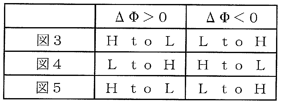
[0036] 図 2に示す本実施の形態が適用される膜面入射構成の光記録媒体 20の層構成を 、従来構成として説明した図 1における基板入射構成の光記録媒体 10と比較しなが ら説明する。ここで、図 1に示す光記録媒体 10及び図 2に示す光記録媒体 20の層構 成を、反射基準面で反射される光の位相に注目して区別して説明するために、図 1 で基板溝部 16へ記録する場合、図 2でカバー層溝間部 25、カバー層溝部 26に記 録する場合のそれぞれに対応して、図 3、図 4、図 5を用いて検討を行う。 [0036] The layer configuration of the film-side incident optical recording medium 20 to which the present embodiment shown in FIG. 2 is applied is compared with the optical recording medium 10 having the substrate incident configuration in FIG. 1 described as the conventional configuration. Will be explained. Here, in order to distinguish and explain the layer structure of the optical recording medium 10 shown in FIG. 1 and the optical recording medium 20 shown in FIG. 2 by focusing on the phase of the light reflected by the reflection reference plane, FIG. When recording in the substrate groove 16, the investigation is performed with reference to FIGS. 3, 4, and 5 corresponding to the cases of recording in the cover layer groove 25 and cover layer groove 26 in FIG. 2.
[0037] 図 3は、従来構成である図 1の基板入射構成の基板 11側から入射する記録再生光 ビーム 17の反射光を説明するための図である。 FIG. 3 is a diagram for explaining the reflected light of the recording / reproducing light beam 17 incident from the substrate 11 side in the substrate incidence configuration of FIG. 1 which is a conventional configuration.
図 4は、膜面入射型媒体 (光記録媒体 20)の層構成とカバー層溝間部 25部に記録 する場合の位相差を説明する図である。 FIG. 4 is a diagram for explaining the layer structure of the film surface incident type medium (optical recording medium 20) and the phase difference in the case of recording in the cover layer groove portion 25 part.
図 5は、膜面入射型媒体 (光記録媒体 20)の層構成とカバー層溝部 26に記録する 場合の位相差を説明する図である。 FIG. 5 is a diagram for explaining the layer structure of the film surface incident type medium (optical recording medium 20) and the phase difference when recording is performed in the cover layer groove 26. FIG.
即ち、図 4及び図 5は、図 2の膜面入射構成の光記録媒体 20において、膜面入射 構成のカバー層 24の入射面 28側から入射する記録再生光ビーム 27の反射光を説
明するための図である。図 4が、本実施の形態が適用される光記録媒体 20における カバー層溝間部 (基板溝部) 25にピットを形成する。図 5は、本発明効果の対比説明 のために、同じ膜面入射構成でありながら、カバー層溝部 (基板溝間部) 26にピット を形成する。 4 and 5 illustrate the reflected light of the recording / reproducing light beam 27 incident from the incident surface 28 side of the cover layer 24 having the film surface incident structure in the optical recording medium 20 having the film surface incident structure in FIG. It is a figure for clarification. In FIG. 4, pits are formed in the cover layer groove portion (substrate groove portion) 25 in the optical recording medium 20 to which the present embodiment is applied. In FIG. 5, pits are formed in the cover layer groove portion (inter-substrate groove portion) 26 with the same film surface incidence configuration for the purpose of comparing the effects of the present invention.
[0038] 図 3、図 4、図 5では、それぞれ、 (a)が記録前、 (b)が記録後の記録ピットを含む断 面図である。以下において、記録ピットを形成するほうの溝ないし溝間部を、「記録溝 部」、その間を「記録溝間部」と称する。即ち、従来構成の図 3においては、基板溝部 16が「記録溝部」であり、記録溝間部 15が「記録溝間部」である。また、本発明に係る 図 4においては、カバー層溝間部 25が「記録溝部」であり、カバー層溝部 26が「記録 溝間部」となる。他方、対比説明である図 5においては、カバー層溝部 26が「記録溝 部」であり、カバー層溝間部 25が「記録溝間部」となる。 In FIG. 3, FIG. 4, and FIG. 5, (a) is a sectional view including a recording pit before recording, and (b) is a recording pit after recording. Hereinafter, a groove or an inter-groove portion that forms a recording pit is referred to as a “recording groove portion”, and a portion between them is referred to as a “recording groove portion”. That is, in FIG. 3 of the conventional configuration, the substrate groove 16 is a “recording groove”, and the recording groove 15 is a “recording groove”. In FIG. 4 according to the present invention, the cover layer groove portion 25 is a “recording groove portion”, and the cover layer groove portion 26 is a “recording groove portion”. On the other hand, in FIG. 5, which is a comparative explanation, the cover layer groove portion 26 is a “recording groove portion”, and the cover layer groove portion 25 is a “recording groove portion”.
[0039] 先ず、記録溝部の反射光と記録溝間部の反射光の位相差を求めるに当たり、位相 の基準面を A— A'で定義する。図 3,図 4,図 5において、それぞれの未記録状態の 図(a)においては、 A— A'は、それぞれ、記録溝部における記録層 12Z基板 11界 面(図 3 (a) )、記録溝間部における記録層 22Zカバー層 24界面(図 4 (a) )、記録溝 部における記録層 22Zカバー層 24界面(図 5 (a) )に対応している。一方、図 3,図 4 ,図 5の記録後状態の図(b)においては、 A-A'は、それぞれ、記録溝部における 記録層 12 (混合層 16m) Z基板 11界面(図 3 (b) )、記録溝間部における記録層 22 Zカバー層 24界面(図 4 (b) )、記録溝部における記録層 22 (混合層 26m) Zカバー 層 24界面(図 4 (b) )に対応している。 A—A'面より手前 (入射側)では、光路によつ て光学的な差は生じない。また、記録前の記録溝部における反射基準面を B—B'、 記録前の基板 21 (図 3)もしくはカバー層 24 (図 4)の記録溝部底面 (記録層 12Z基 板 11、記録層 22Zカバー層 24界面)を C C'で定義する。図 3及び図 5の記録前 においては、 A— A,と C— C,は一致する。 First, in obtaining the phase difference between the reflected light from the recording groove and the reflected light between the recording grooves, a phase reference plane is defined as A−A ′. 3, 4, and 5, in each unrecorded state (a), A−A ′ is the recording layer 12Z substrate 11 interface (FIG. 3 (a)) and recording in the recording groove, respectively. This corresponds to the recording layer 22Z cover layer 24 interface (FIG. 4 (a)) in the groove portion and the recording layer 22Z cover layer 24 interface (FIG. 5 (a)) in the recording groove portion. On the other hand, in FIG. 3, FIG. 4 and FIG. 5 (b) in the post-recording state, AA ′ is the recording layer 12 (mixed layer 16m) Z substrate 11 interface (FIG. 3 (b )), Recording layer 22 in the recording groove area, Z cover layer 24 interface (Fig. 4 (b)), recording layer 22 (mixed layer 26m) in the recording groove part, Z cover layer 24 interface (Fig. 4 (b)) ing. There is no optical difference depending on the optical path in front of the A—A 'plane (incident side). In addition, the reflection reference surface in the recording groove part before recording is BB ′, and the bottom of the recording groove part of the substrate 21 (FIG. 3) or the cover layer 24 (FIG. 4) before recording (recording layer 12Z substrate 11 and recording layer 22Z cover). Layer 24 interface) is defined as C C ′. Before the recordings in Fig. 3 and Fig. 5, A—A and C—C match.
[0040] 記録前の基板溝部での記録層厚みを d、基板溝間部での厚みを dとし、反射基準 [0040] The recording layer thickness at the substrate groove before recording is d, the thickness at the substrate groove portion is d, and the reflection reference
G L G L
面での記録溝部と記録溝間部の段差を d 、基板表面での記録溝間部の段差を d D is the step between the recording groove and the recording groove on the surface, and d is the step between the recording groove on the substrate surface.
GL GL GL GL
とする。図 3の場合には、 d は、記録層 12の記録溝部での埋り方に依存し、 d と And In the case of Fig. 3, d depends on how the recording layer 12 is filled in the recording groove, and d and
S GL GLS S GL GLS
異なる値となる。図 4、図 5の場合には、反射層 23の記録溝部と記録溝間部での被
覆具合によるが、通常は、反射層 23は、記録溝部と記録溝間部でほぼ同じ膜厚とな るので、基板 21表面での段差がそのまま反映されるので、 d =d である。 Different values. In the case of Fig. 4 and Fig. 5, the coverage in the recording groove portion and the recording groove portion of the reflective layer 23 is Although it depends on the covering condition, the reflective layer 23 usually has almost the same film thickness at the recording groove portion and the recording groove portion, and therefore the step on the surface of the substrate 21 is reflected as it is, so d = d.
GL GLS GL GLS
[0041] 基板 11, 21の屈折率を n、カバー層 24の屈折率を nとする。記録ピットの形成に The refractive index of the substrates 11 and 21 is n, and the refractive index of the cover layer 24 is n. For recording pit formation
s c s c
より、一般的には、以下のような変化が生じる。記録ピット部 16p, 25p, 26pにおいて 記録層 12, 22の屈折率は、 n力も n, =n— δ nに変化する。また、記録ピット部 16 d d d d More generally, the following changes occur. In the recording pit portions 16p, 25p, and 26p, the refractive index of the recording layers 12 and 22 also changes n force to n, = n−δn. Also, the recording pit part 16 d d d d
p, 25p, 26pにおいて、記録層 12, 22その入射側界面において、記録層 12と基板 11もしくは基板 21とカバー層 24材料との間に混合が生じ、混合層が形成される。さ らに、記録層 12, 22が体積変化を起こして、反射基準面 (記録層 Z反射層界面)の 位置が移動する。尚、通常は、有機物である基板 11, 21もしくはカバー層 24材料と 金属である反射層材料との間での混合層形成は無視できる程度である。そこで、記 録層 12Z基板 11 (図 1)、記録層 22Zカバー層 24 (図 2)間で記録層 12と基板 11も しくは記録層 22とカバー層 24材料の混合がおき、厚さ d の混合層 16m, 25m, 26 In p, 25p, and 26p, mixing occurs between the recording layer 12 and the substrate 11 or the substrate 21 and the cover layer 24 material at the incident-side interface of the recording layers 12 and 22, thereby forming a mixed layer. In addition, the recording layers 12 and 22 undergo volume change, and the position of the reflection reference plane (recording layer Z reflecting layer interface) moves. Normally, the formation of a mixed layer between the organic substrate 11 or 21 or cover layer 24 material and the metal reflective layer material is negligible. Therefore, the recording layer 12 and the substrate 11 or the recording layer 22 and the cover layer 24 are mixed between the recording layer 12Z substrate 11 (Fig. 1) and the recording layer 22Z cover layer 24 (Fig. 2). Mixed layer of 16m, 25m, 26
mix mix
mが形成されるものとする。また、混合層 16m, 25m, 26mの屈折率を、 n ' =n— Let m be formed. In addition, the refractive index of the mixed layer 16m, 25m, 26m is expressed as n ′ = n—
s s δ η (図 3 (b) )、n,=n— δ η (図 4 (b)、図 5 (b) )とする。 Let s s δ η (Fig. 3 (b)), n, = n – δ η (Fig. 4 (b), Fig. 5 (b)).
[0042] この際、記録層 12Z基板 11あるいは、記録層 22Ζカバー層 24界面は、 C— C'を 基準として、記録後は、 d だけ移動する。 d は図 3,図 4,図 5に示すように、記録 bmp bmp [0042] At this time, the interface of the recording layer 12Z substrate 11 or the recording layer 22 and the cover layer 24 moves by d after recording with reference to C—C ′. d is recorded bmp bmp as shown in Fig. 3, Fig. 4 and Fig. 5.
層 12, 22内部へ移動する方向を正とする。逆に d が負であれば、記録層 12, 22 bmp The direction of movement into layers 12 and 22 is positive. Conversely, if d is negative, the recording layer 12, 22 bmp
が C— C'面を超えて、膨張することを意味する。また、もし、図 3の記録層 12Z基板 1 1、図 4、図 5の記録層 22Zカバー層 24間に両者の混合を妨げる界面層を設けた場 合には、 d =0となりうる。但し、記録層 12, 22の体積変化により d の変形は生じ mix bmp Means that it expands beyond the C—C ′ plane. Also, if an interface layer that prevents mixing of the two is provided between the recording layer 12Z substrate 11 in FIG. 3, the recording layer 22Z cover layer 24 in FIGS. 4 and 5, d = 0. However, the deformation of d occurs due to the volume change of the recording layers 12, 22 mix bmp
うる。色素混合が起きない場合の基板 21またはカバー層 24の d 変形に伴う屈折率 bmp sell. Refractive index bmp associated with d deformation of substrate 21 or cover layer 24 when dye mixing does not occur
変化の影響は、小さく無視できると考えられる。 The effect of change is considered to be small and negligible.
[0043] 他方、記録溝部での反射基準面の移動量を記録前の反射基準面の位置 B— B'を 基準として d とする。 d は、図 3,図 4,図 5に示すように、記録層 12, 22が収縮する pit pit On the other hand, the amount of movement of the reflection reference surface in the recording groove is defined as d with reference to the position B—B ′ of the reflection reference surface before recording. d is the pit pit where the recording layers 12 and 22 contract as shown in FIGS.
方向(反射基準面が記録層 12, 22内部へ移動する方向)を正とする。逆に d が負 pit であれば、記録層 12, 22が B— B'面を超えて、膨張することを意味する。記録後の 記録層膜厚は、 The direction (direction in which the reflection reference plane moves into the recording layers 12 and 22) is positive. Conversely, if d is negative pit, it means that the recording layers 12 and 22 expand beyond the B—B ′ plane. The recording layer thickness after recording is
d =d d — d (1)
となる。尚、 d 、d、d、d 、n、n、n、d は、その定義及び、物理的特性から負d = dd — d (1) It becomes. D, d, d, d, n, n, n, and d are negative due to their definition and physical characteristics.
GL G L mix d c s Ga GL G L mix d c s Ga
の値をとらない。 Do not take the value of.
このような記録ピットのモデルィ匕や、以下で述べる位相の見積もり方法は公知の方 法を用いた (非特許文献 1)。 A known method was used for such a recording pit model and a phase estimation method described below (Non-patent Document 1).
[0044] さて、位相の基準面 A— A'における記録溝部と記録溝間部の再生光 (反射光)の 位相差を記録前と記録後で求める。記録前における記録溝部と記録溝間部の反射 光の位相差を b、記録後、記録ピット部 16p, 25p, 26pと記録溝間部の反射光の 位相差を Φ aとし、 Φで総称する。いずれも、 Now, the phase difference of the reproduction light (reflected light) between the recording groove portion and the recording groove portion on the phase reference plane A—A ′ is obtained before and after recording. The phase difference between the reflected light between the recording groove part and the recording groove part before recording is b, and after recording, the phase difference between the reflected light between the recording pit parts 16p, 25p, 26p and the recording groove part is Φ a, and is generally referred to as Φ. . Both
Φ = Φ1)又は 0>a Φ = Φ1) or 0> a
= (記録溝間部の反射光位相) - (記録溝部 (記録後はピット部を含む)の位相) (2 ) = (Reflected light phase between recording grooves)-(Phase of recording groove (including pit after recording)) (2)
Φ = Φ1)又は 0>a Φ = Φ1) or 0> a
= (2π/λ) ·2·{ (記録溝間部光路長) - (記録溝部 (記録後はピット部を含む)の 光路長) } (3) = (2π / λ) · 2 · {(Optical path length between recording grooves)-(Optical path length of recording groove (including pit after recording))} (3)
として定義する。 Define as
[0045] ここで、(3)式にぉ 、て係数 2が掛力つて 、るのは、往復の光路長を考えるためで ある。 Here, the reason why the coefficient 2 is applied to the equation (3) is to consider the optical path length of the round trip.
図 3においては、 In Figure 3,
Φ1) =(2πΖλ)·2· (η 'd +n -d -n -d ) Φ1) = (2πΖλ) 2 (η 'd + n -d -n -d)
1 s GL d L d G 1 s GL d L d G
= (4π/λ) ·{η -d n ' (d — d )} (4) = (4π / λ) · {η -d n '(d — d)} (4)
s GL d G L s GL d G L
a =(2π/λ) ·2·{η -d +n · (d — d ) +n -d -[(n - δ n ) · (d -d a = (2π / λ) 2 ・ {η -d + n (d-d) + n -d-[(n-δ n) (d -d
L s mix bmp d L d d G pit
L s mix bmp d L dd G pit
= Φ1) + Δ Φ (5) = Φ1) + Δ Φ (5)
但し、 However,
Δ Φ = (4π/λ){(η -n) -d +n -d + δη -d + δ n · (d -d — d )} d s bmp d pit s mix d G pit bmp Δ Φ = (4π / λ) {(η -n) -d + n -d + δη -d + δ n (d -d — d)} d s bmp d pit s mix d G pit bmp
(6) (6)
である。また、記録溝部が入射側力も見て記録溝間部より手前にあるから、 Φbl>o である。
[0046] 一方、図 4においては、 It is. In addition, since the recording groove portion is in front of the recording groove portion with reference to the incident side force, Φb l > o. On the other hand, in FIG.
Φ1) (Φ1)
-n )-(d d )-n -d } (7) -n)-(d d) -n -d} (7)
二 b + ΔΦ (8) Two b + ΔΦ (8)
2 2
但し、 However,
ΔΦ = (4π/λ){(η -n)-d +n -d + δη -d ΔΦ = (4π / λ) {(η -n) -d + n -d + δη -d
d pit c mix d pit c mix
である。また、記録溝部が入射側力も見て記録溝間部より奥にあるから、 bく 0で It is. In addition, since the recording groove part is behind the recording groove part as seen from the incident side force,
2 ある。 There are two.
[0047] さらに、図 5においては、 [0047] Further, in FIG.
Φ1) } Φ1)}
= (4π/λ)·{(η -n)-(d -d )+n -d } (10)
= (4π / λ) · {(η -n)-(d -d) + n -d} (10)
= b +ΔΦ (11) = b + ΔΦ (11)
3 Three
但し、 However,
ΔΦ = (4π/λ){(η -n)-d +n -d + δη -d + δη -(d -d — d )} d c bmp d pit c mix d L pit bmp ΔΦ = (4π / λ) {(η -n) -d + n -d + δη -d + δη-(d -d — d)} d c bmp d pit c mix d L pit bmp
(12) (12)
である。また、記録溝部のほうが入射側から見て記録溝間部より手前にあるから、 Φb >0である。 It is. In addition, since the recording groove portion is in front of the recording groove portion when viewed from the incident side, Φb> 0.
3 Three
[0048] Δ Φ力 記録により生じたピット部での位相変化であり、(12)式で dと dが入れか [0048] Δ Φ force A phase change in the pit caused by recording.
L G L G
わっていることを除けば、いずれの場合も同じ式で表現できる。また、以後、 b、 Φ b、 bを総称して bで表し、 0>a、 0>a、 0>aを総称して Φ aであらわす。 Except for the difference, it can be expressed by the same formula in both cases. In the following, b, Φb, and b are generically represented by b, and 0> a, 0> a, and 0> a are collectively represented by Φa.
2 3 1 2 3 2 3 1 2 3
Δ Φによって生じる信号の変調度 mは、 The degree of modulation m of the signal produced by ΔΦ is
= (ΔΦ/2)2 (14)
となる。最右辺( 14)は Δ Φが小さ 、場合の近似である。 = (ΔΦ / 2) 2 (14) It becomes. The rightmost side (14) is an approximation when ΔΦ is small.
[0049] I Δ Φ Iが大きければ、変調度は大きくなるのである力 通常は、記録による位相 の変化 I Δ Φ Iは、 0から πの間にあり、通常は π /2程度以下であると考えられる 。実際上、従来の CD—R、 DVD— Rをはじめとする従来の色素系記録層では、その ような大きな位相変化は報告されておらず、また、前述のように青色波長域では、色 素の一般的特性から尚さら位相変化は小さくなる傾向にあるからである。逆に、 I Δ Φ Iが πを超える変化は、記録前後でプッシュプルの強制を反転させる可能性、プ ッシュプル信号の変化が大きくなりすぎる可能性があり、トラッキングサーボの安定性 維持の面力 好ましくない。 [0049] The force that increases the degree of modulation when I ΔΦ I is large. Usually, the phase change I ΔΦ I due to recording is between 0 and π, and usually less than about π / 2. it is conceivable that . In fact, in conventional dye-based recording layers such as conventional CD-R and DVD-R, such a large phase change has not been reported, and in the blue wavelength region as mentioned above, This is because the phase change tends to be small from the general characteristics of the above. Conversely, if I ΔΦ I exceeds π, the push-pull force may be reversed before and after recording, and the push-pull signal may change too much. It is not preferable.
[0050] ここで、図 6は、記録溝部と記録溝間部の位相差と反射光強度の関係を説明する 図である。図 6では、 I Φ Iと記録前後の記録溝部における反射光強度の関係が示 されている。ここでは、簡単のため、記録層 12, 22の吸収の影響は無視している。図 3、図 5の構成では、通常、 Φ1) >0となるので、 Δ Φ >0なる場合が、図 6の I Φ I力 S 増加する方向である。つまり、 bが増加して Φ aとなることを示す。 Here, FIG. 6 is a diagram for explaining the relationship between the phase difference between the recording groove portion and the recording groove portion and the reflected light intensity. Fig. 6 shows the relationship between IΦI and the reflected light intensity at the recording groove before and after recording. Here, for the sake of simplicity, the effect of absorption of the recording layers 12 and 22 is ignored. In the configurations of FIG. 3 and FIG. 5, Φ1)> 0 is usually satisfied, and therefore the case where ΔΦ> 0 is the direction in which the IΦI force S of FIG. 6 increases. That is, b increases to become Φ a.
[0051] 一方、図 4の構成では、通常、 Φ1)< 0となるので、 Δ Φく 0なる場合が、図 6の | Φ [0051] On the other hand, in the configuration of FIG. 4, Φ1) <0 is usually satisfied.
Iが増加する方向である。つまり、図 6における横軸に(一 1)を乗じたものに相当す る。よって、 I b Iが増加して I 0>a Iとなることを示す。 I is in the direction of increasing. In other words, this is equivalent to multiplying the horizontal axis in Fig. 6 by (1 1). Therefore, I b I increases and I 0> a I.
[0052] 平面状態 (d =0)での記録溝部の反射率を ROとすると、 [0052] When the reflectance of the recording groove in the planar state (d = 0) is RO,
GL I Φ Iが大きくなるにつ れ、記録溝部と記録溝間部の反射光の位相差 bから干渉効果が生じ、反射光強度 が低下していく。そして、位相差 I Φ Iが π (半波長)と等しくなると、反射光強度は 極小値となる。さらに、 I Φ Iが πを超えて増大すると、反射光強度は増加に転じ、 I Φ I = 2 πで極大値をとる。 As GL I ΦI increases, an interference effect arises from the phase difference b of the reflected light between the recording groove and the recording groove, and the reflected light intensity decreases. And when the phase difference I Φ I becomes equal to π (half wavelength), the reflected light intensity becomes the minimum value. Furthermore, when I Φ I increases beyond π, the reflected light intensity starts to increase, and reaches a maximum at I Φ I = 2 π.
[0053] ここで、プッシュプル信号強度は、位相差 I Φ I力 π /2の時に最大となり、 πの ときに極小となって、極性が反転する。以後、再び増カロ'減少し、 2 πにおいて極小と なって再び極性が逆転する。以上の関係は、位相ピットによる ROM媒体における、 ピット部の深さ (d に相当)と反射率の関係とまったく同様である (非特許文献 5)。 [0053] Here, the push-pull signal intensity becomes maximum when the phase difference I Φ I force π / 2, becomes minimum when π, and the polarity is inverted. After that, the calorie increases again and it becomes a minimum at 2π and the polarity is reversed again. The above relationship is exactly the same as the relationship between the depth of the pit part (corresponding to d) and the reflectance in the ROM medium with phase pits (Non-patent Document 5).
GL GL
[0054] 以下に、プッシュプル信号について若干の説明をする。 [0054] The push-pull signal will be briefly described below.
図 7は、記録信号 (和信号)とプッシュプル信号 (差信号)を検出する 4分割ディテク
ターの構成を説明するための図である。 4分割ディテクタ一は、 4つの独立した光検 出器力もなり、それぞれの出力を Ia、 Ib、 Ic、 Idとする。図 7の記録溝部及び記録溝間 部からの 0次回折光及び 1次回折光は、 4分割ディテクタ一にて受光され、電気信号 に変換される。 4分割ディテクタ—力 の信号から、下記の演算出力を得る。 Figure 7 shows a quadrant detector that detects the recording signal (sum signal) and push-pull signal (difference signal). It is a figure for demonstrating the structure of a motor. The quadrant detector also has four independent optical detector forces, each of which is designated as Ia, Ib, Ic, and Id. The zero-order diffracted light and the first-order diffracted light from the recording groove portion and the recording groove portion in FIG. 7 are received by the four-divided detector 1 and converted into electric signals. The following calculation output is obtained from the quadrant detector force signal.
Isum= (la+Ib+Ic +Id) (15) Isum = (la + Ib + Ic + Id) (15)
IPP= (la+Ib) - (lc+Id) (16) IPP = (la + Ib)-(lc + Id) (16)
なる演算出力が得られる。 An arithmetic output is obtained.
[0055] また、図 8は、実際に、複数の記録溝、溝間を横断しながら得られる出力信号を低 周波通過フィルタ—(カットオフ周波数 30kHz程度)を通過させた後に検出する信号 を示す図である。 [0055] FIG. 8 shows the signals detected after the output signal actually passed through the plurality of recording grooves and between the grooves is passed through a low-frequency pass filter (cutoff frequency of about 30 kHz). FIG.
図 8において、 Isum 、Isum は、記録溝部あるいは記録溝間部のちょうど真上 In Fig. 8, Isum and Isum are just above the recording groove or between the recording grooves.
max mm max mm
(中心軸上)を光ビームが通過したときに対応する。 Isum は、 Isum信号の peak— to— peakでの信号振幅である。 IPP は、プッシュプル信号の Peak— to— peakの 信号振幅である。プッシュプル信号強度とは、 IPP のことを 、、プッシュプル信 号 IPPそのものとは区別する。 Corresponds when the light beam passes (on the central axis). Isum is the signal amplitude from peak-to-peak of the Isum signal. IPP is the peak-to-peak signal amplitude of the push-pull signal. Push-pull signal strength distinguishes IPP from push-pull signal IPP itself.
トラッキングサ一ボは、図 8 (b)のプッシュプル信号 (IPP)を誤差信号として、フイ一 ドバック'サ―ボを行う。図 8 (b)で、 IPP信号の極性が、 +から—に変化する点力 記 録溝部中心に対応し、—力も +に変化する点が、記録溝間部に対応する。プッシュ プルの極性が反転するとは、この符号の変化が逆になることである。符合が逆になる と、記録溝部にサ―ボが力かった (即ち、集光ビームスポットが記録溝部に照射され る)つもりが、逆に記録溝間部にサ―ボが力かるような不都合を起こす。 The tracking servo performs a feedback servo using the push-pull signal (IPP) in Fig. 8 (b) as an error signal. In Fig. 8 (b), the point where the IPP signal polarity changes from + to-corresponds to the center of the recording groove, and the point where the force changes to + corresponds to the recording groove. An inversion of the push-pull polarity means that this sign change is reversed. When the sign is reversed, the servo is applied to the recording groove (that is, the focused beam spot is applied to the recording groove), but the servo is applied to the recording groove. Cause inconvenience.
[0056] 記録溝部にサーボが力かったときの Isum信号力 記録信号であり、本実施の形態 では、記録後に増加する変化を示す。ここで、 [0056] Isum signal force when the servo is applied to the recording groove. This is a recording signal, and in this embodiment, the change increases after recording. here,
IPP =IPP /{ (Isum +Isum ) /2} (17) IPP = IPP / {(Isum + Isum) / 2} (17)
norm max min norm max min
なる演算出力は、規格ィ匕プッシュプル信号強度 (IPP )という。 The calculated output is called standard push-pull signal strength (IPP).
norm norm
(17)式で IPP のかわりに、 IPPを用いたもの力 規格化プッシュプル信号である このような規格ィ匕プッシュプル信号及び規格ィ匕プッシュプル信号強度の定義は、通
常の、記録型 CD、 DVDの規格で規定された一般的なものと同等である。 In Equation (17), instead of IPP, the power using IPP is a standardized push-pull signal. It is equivalent to the general one defined in the standard of recordable CD and DVD.
[0057] 図 6に示すような位相差と反射光強度の関係は、上記(13)式からも分力るように、 周期的である。記録前後での I Φ Iの変化、即ち I Δ Φ Iは、色素を主成分とする 媒体では、通常、(π Ζ2)程度より小さい。逆に、本実施の形態では、記録による I Φ Iの変化は、最大でも π以下であるとする。そのために、必要なら、記録層膜厚を 適宜薄くすればよい。 [0057] The relationship between the phase difference and the reflected light intensity as shown in FIG. 6 is periodic as indicated by the above equation (13). The change in I Φ I before and after recording, that is, I Δ Φ I, is usually smaller than (π Ζ 2) in a medium having a dye as a main component. Conversely, in the present embodiment, it is assumed that the change in IΦI due to recording is at most π. Therefore, if necessary, the recording layer thickness can be reduced appropriately.
[0058] ここで、位相基準面 A— Α,からみて、記録ピット部 16p, 25p, 26pの形成により記 録溝部の反射光の位相(あるいは光路長)が記録前より小さくなつた場合 (記録前より 位相が遅れた場合)、即ち、 Δ Φ >0である場合、入射側から見て反射基準面の光 学的距離 (光路長)は減少し、光源に (あるいは、位相の基準面 A— A'に)近寄った ことになる。したがって、図 3においては、記録溝部の反射基準面が下方に移動した( d が増加)と同等の効果があり、結果として記録ピット部 16pの反射光強度は減少す [0058] Here, when the phase (or optical path length) of the reflected light in the recording groove portion becomes smaller than before recording due to the formation of the recording pit portions 16p, 25p, and 26p as viewed from the phase reference plane A—Α (recording) When the phase is delayed from before, that is, ΔΦ> 0, the optical distance (optical path length) of the reflection reference plane decreases from the incident side, and the light source (or phase reference plane A — It ’s close to A '). Therefore, in FIG. 3, there is an effect equivalent to the fact that the reflection reference surface of the recording groove has moved downward (increases d), and as a result, the reflected light intensity of the recording pit 16p decreases.
GL GL
る。図 4では、逆に記録溝部の反射基準面が上方に移動した (d が減少)と同等の The In Fig. 4, conversely, the reflection reference plane of the recording groove is moved upward (d is decreased).
GL GL
効果があり、結果として、記録ピット部 25pの反射光強度は増加する。図 5では、記録 溝部の反射基準面が上方に移動した (d が増加)と同等の効果があり、結果として、 As a result, the reflected light intensity of the recording pit portion 25p increases. In Fig. 5, there is an effect equivalent to the fact that the reflection reference surface of the recording groove has moved upward (d increased). As a result,
GL GL
記録ピット部 26pの反射光強度は減少する。 The reflected light intensity of the recording pit part 26p decreases.
[0059] 一方、位相基準面 A— A'からみて、記録ピット部 16p, 25p, 26pの反射光の位相 [0059] On the other hand, as viewed from the phase reference plane A—A ′, the phase of the reflected light from the recording pit portions 16p, 25p, 26p
(あるいは光路長)が記録前より大きくなつた場合 (記録前より位相が遅れた場合)、 Δ Φ < 0である場合、入射側から見て反射基準面の光学的距離 (光路長)は増加し、 光源に(あるいは、位相基準面 A— A'に)から遠ざかったことになる。図 3においては 、記録溝部の反射基準面が上方に移動した (d が減少)と同等の効果があり、結果 (Or the optical path length) becomes larger than before recording (when the phase is delayed from before recording), if ΔΦ <0, the optical distance (optical path length) of the reflection reference surface increases when viewed from the incident side However, it is away from the light source (or to the phase reference plane A—A ′). In Fig. 3, there is an effect equivalent to that when the reflection reference surface of the recording groove is moved upward (d is decreased).
GL GL
として記録ピット部 16pの反射光強度は増加する。図 4では、逆に記録溝部の反射基 準面が下方に移動した (d が増加)と同等の効果があり、結果として、記録ピット部 2 As a result, the reflected light intensity of the recording pit portion 16p increases. In Fig. 4, conversely, the reflection reference surface of the recording groove has the same effect as moving downward (increasing d).
GL GL
5pの反射光強度は減少する。図 5では、記録溝部の反射基準面が下方に移動した( d が減少)と同等の効果があり、結果として、記録ピット部 26pの反射光強度は増加 The reflected light intensity of 5p decreases. In Fig. 5, there is an effect equivalent to the fact that the reflection reference surface of the recording groove has moved downward (decreasing d), and as a result, the reflected light intensity of the recording pit part 26p increases.
GL GL
する。ここで、記録ピット部の反射光強度が記録後に減少する力 増加するかという、 反射光強度の変化の方向を記録 (信号)の極性という。 To do. Here, the direction of change in reflected light intensity, which is whether the reflected light intensity at the recording pit portion increases after recording, is called the recording (signal) polarity.
[0060] したがって、記録ピット部 16p, 25p, 26pで Δ Φ >0となる位相変化がおきるならば
、図 3、図 5の記録溝部においては、記録により反射光強度が低下する「High to L owj (以下、単に、 HtoLと記す)となる信号の極性の変化を利用することが好ましぐ 図 4の記録溝部においては、記録により反射光強度が増加する「Low to High] ( 以下、単に、 LtoHと記す)となる極性を利用することが好ましい。他方、 Δ Φく 0とな る位相変化がおきるならば、図 3、図 5の記録溝部においては LtoHとなる極性を利 用することが好ましぐ図 4の記録溝部においては HtoLとなる極性を利用することが 好ましい。以上の関係を表 1にまとめて示す。表 1は、 Δ Φの符号に対して、図 3、図 4、図 5の構成と記録溝部において、 HtoL、 LtoHいずれの極性の反射光強度変化 が好ましいかを示す。 [0060] Therefore, if a phase change with ΔΦ> 0 occurs in the recording pit portions 16p, 25p, 26p, 3 and 5, it is preferable to use the change in polarity of the signal that becomes “High to Low owj” (hereinafter simply referred to as HtoL) in which the reflected light intensity decreases due to recording. In the recording groove part 4, it is preferable to use a polarity of “Low to High” (hereinafter simply referred to as LtoH) in which the reflected light intensity increases by recording. On the other hand, the phase change becomes ΔΦ 0. 3 and 5, it is preferable to use the polarity that becomes LtoH in the recording groove portion in Fig. 3 and Fig. 5. It is preferable to use the polarity that becomes HtoL in the recording groove portion in Fig. 4. The results are summarized in Table 1. Table 1 shows whether the change in reflected light intensity of the polarity of HtoL or LtoH is preferable in the configuration and recording groove part of FIGS. .
[0061] [表 1] [0061] [Table 1]
[0062] このように、記録ピット形成位置 (記録溝部)が基板 (カバー層)溝部と基板 (カバー 層)溝間部のいずれにあるかによって、また、記録ピット部の反射光の位相変化の方 向によって、記録による反射光の位相変化の方向(増減)が好ましい場合と好ましくな い場合がある。従来、相変化型記録媒体では、位相差記録として利用する例がある 力 色素記録層を用いた追記型媒体では、必ずしも、具体的かつ積極的に使い分け られている例はな力つた。なぜなら、従来の色素記録層追記型媒体のほとんどが、図 1の構成の基板溝部に記録を行うこと、平面状態の屈折率変化による HtoL記録を前 提としており、あえて、溝間部へ、位相の変化を主とし、「干渉効果を考慮した反射光 強度の変ィ匕」を主とした LtoH記録を行うことがほとんどな力つた力もである。 [0062] As described above, depending on whether the recording pit formation position (recording groove portion) is located between the substrate (cover layer) groove portion or the substrate (cover layer) groove portion, the phase change of the reflected light of the recording pit portion is also affected. Depending on the direction, the direction (increase / decrease) of the phase change of reflected light by recording may or may not be preferable. Conventionally, there are examples of phase change recording media that are used as phase difference recording. In write-once media using a dye recording layer, there has always been a specific and positive usage example. This is because most of the conventional dye recording layer write-once media are premised on recording in the substrate groove part of the configuration in Fig. 1 and HtoL recording by changing the refractive index in the planar state. It is also a force that is most effective to perform LtoH recording mainly on the change of the reflection, mainly on the “change of reflected light intensity considering the interference effect”.
[0063] (位相変化 Δ Φの符号と記録極性の好ま 、態様にっ 、て) [0063] (Preference of phase change ΔΦ and recording polarity, depending on the mode)
さて、記録ピット部 16p, 25p, 26pでは、光学的に記録層 12, 22の屈折率変化あ るいは変形による位相の変化 (即ち、位相差を考慮した反射光強度の変化に寄与す る。)と、屈折率変化による平面状態での反射光強度の変化 (即ち、位相差を考慮し ない反射光強度の変化)が、同時に起こりうる。これらの変化の方向がそろっているこ
とが好ましい。つまり、記録信号の極性が、記録パワーや記録ピットの長さ、大きさに 寄らず一定であるためには、個々の反射光強度変化がそろって 、ることが好ま U、。 以下において、色素記録層媒体で図 4のカバー層溝間部 25に記録を行う場合に、 Δ Φ >0及び Δ Φく 0がどのような場合に生じ、いずれの方向を好適に利用すべき かを、図 3,図 5の場合と比較しつつ検討する。 The recording pit portions 16p, 25p, and 26p optically contribute to changes in the refractive index of the recording layers 12 and 22 or changes in phase due to deformation (that is, changes in reflected light intensity considering the phase difference). ) And a change in reflected light intensity in a planar state due to a change in refractive index (that is, a change in reflected light intensity not considering the phase difference) can occur simultaneously. The direction of these changes is aligned And are preferred. In other words, in order for the polarity of the recording signal to be constant regardless of the recording power and the length and size of the recording pits, it is preferable that the individual reflected light intensity changes match. In the following, when recording is performed on the cover layer groove 25 in FIG. 4 with the dye recording layer medium, ΔΦ> 0 and ΔΦ <0 occur in any case, and which direction should be preferably used. This is compared with the cases of Fig. 3 and Fig. 5.
Δ Φにおいて、 In ΔΦ,
Φ = (n -n ) -d (18) Φ = (n -n) -d (18)
bmp d c bmp bmp d c bmp
Φ =n -d (19) Φ = n -d (19)
pit d pit pit d pit
Φ = δ η -d (20) Φ = δ η -d (20)
mix c mix mix c mix
Φ = δ η - (d -d -d ) = δ η -d (21) Φ = δ η-(d -d -d) = δ η -d (21)
n d G pit bmp d Ga n d G pit bmp d Ga
とすると、 Φ Φ
bmpは、記録層入射側界面の変形 (移動)による位相変化、 Φ bmp is the phase change due to deformation (movement) of the recording layer incident side interface, Φ
pitは記録層 pit is the recording layer
12, 22Z反射層 13, 23界面の変形 (移動)による位相変化、 Φ は混合層 16m, 2 12, 22Z reflective layer 13, 23 Phase change due to deformation (movement) of interface, Φ is mixed layer 16m, 2
mix mix
5m, 26m形成による位相変化、 Φ は記録層 12, 22の屈折率変化による位相変化 に対応する。これらの位相変化が大きくて、変化の方向、即ち、 Φ 、 Φ 、 Φ 、 Φ Phase change due to 5m and 26m formation, Φ corresponds to phase change due to refractive index change of recording layers 12 and 22. These phase changes are large and the direction of the change, that is, Φ, Φ, Φ, Φ
bmp pit mix の符号がそろっていることが、変調度を大きくし、かつ、特定の信号極性の信号波形 をひずませずに、良好な記録特性を得るために重要なことである。 The fact that the bmp pit mix codes are aligned is important for obtaining good recording characteristics without increasing the degree of modulation and distorting the signal waveform of a specific signal polarity.
このうち、位相変化の方向をそろえるためには、上記、 Φ 、 Φ 、 Φ 、 Φ に係 Among these, in order to align the direction of phase change, it is related to the above Φ, Φ, Φ, Φ.
bmp pit mix n る複数の物理パラメーターをすベて正確に制御するよりは、できるだけ少ない要素に 限定して制御することが望ま U、。 bmp pit mix n It is desirable to control only as few elements as possible rather than controlling all physical parameters accurately.
先ず、記録層入射側界面に界面層を設けるなどして、 d =0とすることも好ましい First, it is also preferable to set d = 0 by providing an interface layer on the recording layer incident side interface.
mix mix
。 d による位相差変化は、あまり大きくできないので積極的に利用しにくいだけでな mix . The phase difference change due to d cannot be increased so much that it is difficult to use actively.
ぐその厚みの制御が難しいからである。よって、記録層入射側界面に界面層を設け るなどして、 d =0とすることが好ましい。 This is because it is difficult to control the thickness of the gusset. Therefore, it is preferable to set d = 0 by providing an interface layer at the recording layer incident side interface.
mix mix
次いで、変形に関しては、一箇所に集中し、かつ、一方向に限定されることが好ま しい。複数の変形部位よりも、一箇所の変形部位をより正確に制御するほうが良好な 信号品質が得られやす!/ヽからである。 Next, the deformation is preferably concentrated in one place and limited to one direction. It is easier to obtain better signal quality by controlling one deformed part more accurately than multiple deformed parts!
従って、本実施の形態においては、 φ と φ のうちのいずれかと、 φを主として Therefore, in this embodiment, either φ or φ and φ are mainly used.
bmp pit n bmp pit n
利用することが好ましい。
d に関しては、通常は、基板またはカバー層の膨張あるいは、記録層の体積収縮 pit It is preferable to use it. For d, usually the expansion of the substrate or cover layer or the volume shrinkage of the recording layer pit
が主要因であるから、 d >0となることが多い。これは、 Φ には有利ではあるが、 d pit pit GaIs the main factor, so d> 0 often. This is advantageous for Φ, but d pit pit Ga
、すなわち、 Φηには不利である。一方、記録層の吸収は、記録層の厚みの中間部か ら入射側界面側で最も高くなるので、その部分で最も高温となり、反射層の界面側は 、発熱量が相対的に小さい。また、反射層に高放熱性材料を用いれば、その記録層 の発熱の影響は、大部分記録層の入射側界面に集中する。発熱が集中するのは、 図 4では、記録層 22とカバー層 24側の界面である。したがって図 4の構成では、色 素の入射側界面、即ちカバー層 24との界面に変形が生じる。このため、 d は自然と pit 小さくなるので寄与は小さい。従来構成とは異なり、基板 21側変形の影響は少ないと 考えられ、実際上、 d 0とみなせる。このことは、むしろ、制御すべき変形要素を d pit b に集約したことがよ!、ことを示唆して!/、る。 That is, it is disadvantageous for Φ η . On the other hand, the absorption of the recording layer is highest on the incident side interface side from the intermediate part of the thickness of the recording layer, so that the temperature is highest at that part, and the heat generation amount is relatively small on the interface side of the reflective layer. Further, if a high heat dissipation material is used for the reflective layer, the heat generation effect of the recording layer is mostly concentrated on the incident side interface of the recording layer. In FIG. 4, the heat generation is concentrated at the interface between the recording layer 22 and the cover layer 24 side. Therefore, in the configuration of FIG. 4, deformation occurs at the interface on the incident side of the dye, that is, the interface with the cover layer 24. For this reason, d contributes little because it naturally decreases pit. Unlike the conventional configuration, the effect of deformation on the substrate 21 side is considered to be small, and can be regarded as d 0 in practice. Rather, this suggests that the deformation elements to be controlled have been consolidated into d pit b! /
mp mp
この場合、 Φ は、(21)式力 分力るように、色素の屈折率変化 δ η、変形 d 力 S In this case, Φ is the change in the refractive index of the dye δ η and the deformation d force S, as shown by the force in Equation (21).
n d bmp 寄与しており、 Δ Φの大きさと符号に最も重要な要素である。 n d bmp is the most important factor in the magnitude and sign of ΔΦ.
d は後に考慮するとして 4番目の Φ に係る物理現象のうち、記録層屈折率変化 bmp n d is the fourth physical phenomenon related to Φ, which will be considered later.
δ の影響を先ず考察する。記録後の記録層膜厚 d は、その定義上 d >οであるか n Ga Ga First consider the effect of δ. The recording layer thickness d after recording is, by definition, d> ο or n Ga Ga
ら、 δ ηの符号が、 Φ の符号を支配すると考えられる。本発明においては、色素を d n Therefore, it is considered that the sign of δ η dominates the sign of Φ. In the present invention, the dye is d n
主成分とする記録層を用いるが、色素の主吸収帯は、そのもっとも強い吸収波長(吸 収のピーク)力 可視光域 (概ね 400— 800nm)にある吸収帯であるとする。主成分 となる色素の主吸収端近傍の波長で記録再生を行った場合、通常は、記録層の発 熱により、記録層は分解され、吸収が大きく減少するものと考えられる。少なくとも、未 記録状態では主吸収帯では、いわゆるクラマ—ス 'クロ— -ッヒ型の異常分散が存在 し、図 9に示すような屈折率 n及び吸収係数 kの波長依存性が存在すると考えられて いる。主吸収端の長波長端え では、 n = 1. 5〜3程度、 k =0. 1〜1. 5程度となり し d d Although the recording layer is used as the main component, the main absorption band of the dye is the absorption band with the strongest absorption wavelength (absorption peak) force in the visible light region (approximately 400 to 800 nm). When recording / reproduction is performed at a wavelength near the main absorption edge of the main dye, the recording layer is usually decomposed by the heat generation of the recording layer, and the absorption is considered to be greatly reduced. At least in the unrecorded state, there is an anomalous dispersion of the so-called Kuramath's-Kroch type in the main absorption band, and the wavelength dependence of the refractive index n and the absorption coefficient k as shown in Fig. 9 is considered to exist. It has been. At the long wavelength end of the main absorption edge, n = 1.5 to 3 and k = 0.1 to 1.5
うるし、短波長端え では、 n =0. 5〜1. 5程度、 k =0. 1〜1. 5程度となりうる。主 In addition, at the short wavelength end, n = 0 to about 1.5 to 1.5 and k = 0 to about 0.1 to 1.5. main
S d d S d d
吸収端の中央部では、 kが大きくなりすぎる場合があるので、通常は、 k =0. 01〜0 d d Since k may be too large at the center of the absorption edge, usually k = 0.01 to 0 d d
. 6となるよう、ピークの中心力 多少ずれた波長域え 及びえ を記録再生光波長と し S .6 The peak power of the peak is slightly shifted so that
することがある。一方、記録後の屈折率の挙動は、色素によって異なるであろうが、記 録後にもクラマース'クロー-ッヒ関係が維持され、 nが増加するとは限らない。むしろ
この関係が成り立たない場合が多いと考えられる。 There are things to do. On the other hand, the behavior of the refractive index after recording will vary depending on the dye, but the Kramers-Croach relationship is maintained after recording and n does not always increase. Rather In many cases, this relationship does not hold.
[0066] 通常、記録層主成分とする色素の分解温度は、 500°C以下であり、記録光による発 熱によって、記録層主成分の色素は、主吸収端を維持できないまでに分解されるか らである。その場合、クラマ一ス 'クロ一 -ッヒ型の異常分散は存在せず、よって、 n , d [0066] Usually, the decomposition temperature of the dye as the main component of the recording layer is 500 ° C or less, and the dye of the main component of the recording layer is decomposed by the heat generated by the recording light until the main absorption edge cannot be maintained. Because. In that case, there is no anomalous dispersion of the Kuramasu 'Kroi-Schiff type, so n, d
= 1〜1. 5程度の屈折率し力得られない。 = Refractive index of about 1 to 1.5 and power cannot be obtained.
したがって、色素の分解を利用する場合には、 n 、 kが減少する場合を利用したほ d d Therefore, when using the decomposition of dye, the case where n and k decrease is used.
うが色素の選択の幅は広がると考えられる。即ち、 δ η >0である場合を利用するの d It is thought that the range of selection of ginger pigments will widen. That is, use the case where δ η> 0 d
が記録層材料の選択肢が広く好ま ヽ。 However, the choice of recording layer material is widely preferred.
[0067] 尚、記録層内あるいは、その隣接する界面に空洞が発生することも多いが、その場 合にも、空洞内は n ' = 1と考えられるから、屈折率の低下とみなすことができる。空 d [0067] It should be noted that cavities often occur in the recording layer or at the adjacent interface. In this case, however, it is considered that n '= 1 in the cavities, so that it can be regarded as a decrease in refractive index. it can. Sky d
洞が記録層の一部を占めていても、記録層の平均的な屈折率は低下しているとみな せる。この場合も、 δ η >0である。あるいは、記録層色素の吸収に関わる構造の変 d Even if the cave occupies a part of the recording layer, it can be considered that the average refractive index of the recording layer is lowered. Again, δ η> 0. Or, the structural change related to the absorption of the recording layer dye d
ィ匕が小さくても、記録層の温度上昇で記録層体積の膨張が生じて密度が低下しても 、屈折率が低下しうる。なお、以上の屈折率低下のメカニズムのうち、空洞を形成して 、 n ' 1とすることが、最も確実にかつ大きな δ ηを得るために好ましいことであると d d Even if the diameter is small, even if the recording layer volume expands due to the temperature rise of the recording layer and the density decreases, the refractive index can decrease. Of the above refractive index lowering mechanisms, it is preferable to form a cavity and set it to n ′ 1 in order to obtain a large δη most reliably and d d
考えられる。 Conceivable.
[0068] 以上から考えて、記録層主成分の色素の光学的変化 (含む空洞、低密度部等の形 成)を利用するならば、 δ η >0 [0068] Considering the above, if the optical change of the dye as the main component of the recording layer (including formation of cavities, low density parts, etc.) is used, δ η> 0
d 、即ち、屈折率の低下を利用するほうが、色素選択 の範囲が広がり好ましい。前述のように d 〉0であるから、結局、 Φ 〉0を利用する It is preferable to use d, that is, to lower the refractive index because the range of dye selection is widened. As mentioned above, d> 0, so use Φ> 0 in the end
Ga n Ga n
ことが好ましい。 It is preferable.
さて、記録による変質 (分解を伴う)後の色素の屈折率は、概ね基板やカバー層並 に低下すると考えられる。また、空洞形成等でもカバー層同等以下に低下すると考え られる。よって、本実施の形態では、 η ' < ηとなる色素を好適に利用する。従って、 d c Now, it is considered that the refractive index of the dye after alteration (with decomposition) due to recording is almost the same as that of the substrate and cover layer. In addition, the formation of cavities, etc., is considered to decrease to below the cover layer. Therefore, in the present embodiment, a dye satisfying η ′ <η is preferably used. Therefore, d c
δ η > I n -n |と考えられる。一方、 Φ と Φ の大小は、ほぼ、 d の符号に依 d d c bmp n bmp 存する。 d =d — d — d であるから、前述のように d 0とすると、 d =d — d δ η> I n −n | On the other hand, the magnitude of Φ and Φ almost depends on the sign of d d c bmp n bmp. Since d = d — d — d, d = d — d
Ga G pit bmp pit Ga G bm となる。従って、 d く 0であれば、 d > I d Iである。 d >0、つまり、記録層 p bmp Ga bmp bmp Ga G pit bmp pit Ga G bm Therefore, if d is 0, d> I d I. d> 0, that is, recording layer p bmp Ga bmp bmp
の体積収縮がおきるとしても、記録層膜厚が 50%未満になるような極端な記録層の 収縮は、通常考えられない (あるいは、そのような収縮は記録層物質が記録ピット部よ
り流出することを意味するので好ましくないともいえる)ので、同様に、 d >d であ Even if the volume shrinkage of the recording layer occurs, extreme shrinkage of the recording layer such that the film thickness of the recording layer is less than 50% is usually not considered (or such shrinkage is caused by the recording layer material being in the recording pit area). Similarly, d> d.
Ga bmp る。結局、 I Φ I < Φであり、主要な変化は Φ 〖こよるとすると、同様に、 δ η >0 bmp n n d なる変化は、 Φ >0なる変化となり、 Δ Φ >0なる位相変化につながると考えられる。 Ga bmp. After all, if I Φ I <Φ and the main change is Φ 〖, the change δ η> 0 bmp nnd is also the change Φ> 0 and leads to the phase change Δ Φ> 0 it is conceivable that.
[0069] 従来の CD— R等の有機色素系の光ディスクにおいては、 d =d >0とみなし、 mix bmp [0069] In conventional organic dye-based optical discs such as CD-R, d = d> 0 and mix bmp
混合層 16m, 25m, 26mが記録層 12, 22側に入り込むことの寄与が多いと考えら れている(非特許文献 1)。 Φ >0、 Φ >0であり、同様に全体として Δ Φ >0であ pit bmp It is considered that the contribution of the mixed layers 16m, 25m, and 26m entering the recording layers 12 and 22 is large (Non-patent Document 1). Φ> 0, Φ> 0, and ∆ b> 0 as a whole pit bmp
る。逆にいうと、 Δ Φ >0を極力大きくして変調度をとるべく検討が重ねられてきたとい つても過言ではない。従来の図 1の溝部において、 Δ Φ >0なる位相変化を生ぜしめ 、 HtoL記録を実現していることも考えれば、色素を主成分とする記録層 22では、 Δ Φ >0なる位相変化を利用するのが自然である。すなわち、前記記録ピット部 25pで の位相変化が、前記反射層 23の入射光側における nより低い屈折率部の形成によ d The In other words, it is no exaggeration to say that studies have been repeated to increase ΔΦ> 0 as much as possible to obtain the degree of modulation. Considering that the conventional groove portion in Fig. 1 generates a phase change of ΔΦ> 0 and realizes HtoL recording, the recording layer 22 mainly composed of a dye exhibits a phase change of ΔΦ> 0. It is natural to use. That is, the phase change at the recording pit portion 25p is caused by the formation of a refractive index portion lower than n on the incident light side of the reflective layer 23.
るものであることが望ましい。そのことが、色素主成分記録層を利用するに当たって最 も好ましいことなのである。ここで、本実施の形態において重要なことは、 Δ Φ >0な る位相変化を積極的かつ選択的に利用することであって、従来発明のように、入射 側から見て近 ヽ(光路長が小さ 、)溝部に記録することや、 HtoL記録を行うことでは ない。 It is desirable that This is most preferable when the dye main component recording layer is used. Here, what is important in the present embodiment is to actively and selectively use the phase change that satisfies ΔΦ> 0. As in the conventional invention, the proximity (optical path) is viewed from the incident side. It is not recording in the groove) or HtoL recording.
[0070] 従来の青色レーザ光記録に関する先行技術では、 CD— Rや DVD— Rの従来技 術にとらわれ、入射側から見て溝となるカバー層溝部 26 (図 5参照)に、 Δ Φ >0なる 位相変化で、 HtoL記録を行おうとする前提条件力も抜け出せずにいたといえる。あ るいは、位相変化に頼らず 50〜: LOOnmの厚膜記録層として、平面状態で起こる反 射率変化、特に、 δ ηが概ね 1以上となる大きな変化や、同時に起きる吸収係数 kの d d 大きな変化を利用して反射光強度低下、即ち、 HtoL記録をすることを意図していた のである。 [0070] In the prior art relating to the conventional blue laser light recording, the conventional technology of CD-R and DVD-R is used, and the cover layer groove portion 26 (see FIG. 5) that becomes a groove when viewed from the incident side has Δ Φ> With the phase change of 0, it can be said that the precondition force to perform HtoL recording was not lost. Or, without depending on the phase change 50 ~: As the LOOnm thick film recording layer, the reflectivity change that occurs in the planar state, especially the large change that δ η is approximately 1 or more, or the simultaneous absorption coefficient k dd It was intended to reduce reflected light intensity, that is, to perform HtoL recording using a large change.
[0071] ここで、 Δ Φ >0なる位相変化とプッシュプル信号の関係について考察しておく。従 来の CD— Rや DVD—Rの類推力もカバー層溝部 26 (図 5参照)に対する HtoL記 録を行う場合、プッシュプル信号極性が反転しな ヽようにしたければ、 d として、往 Here, the relationship between the phase change of ΔΦ> 0 and the push-pull signal will be considered. When HtoL recording is performed for the analog thrust of the conventional CD-R and DVD-R to the cover layer groove 26 (see Fig. 5), if the push-pull signal polarity should not be reversed, d is the
GL GL
復の光路長が 1波長より大きくなる( I b I > 2 πとなる)ような深い溝段差(「深溝」 Deep groove step ("deep groove") where the return optical path length is greater than one wavelength (IbI> 2π)
3 Three
と称する)か、 bがほとんどゼロであり、力ろうじてプッシュプル信号が出るような溝
段差(「浅溝」と称する)に限られる。深溝の場合、図 6の I b I > 2 πなる斜面で、 矢印 αの方向の位相変化を利用し、光学的に溝が深くなるようにする。この場合、矢 印の始点となる溝深さは、 400nm前後の青色波長では lOOnm程度が必要で、前述 のように狭トラックピッチでは、成形時に不良転写がおきやすぐ量産に困難を伴う。 また、たとえ、所望の溝形状が得られても、溝壁の微小な表面粗さによるノイズが信 号に混入しやすい。さらに、溝底部、側面の壁に反射層 23を均等に形成するのが困 難である。反射層 23自体の溝壁への密着性も悪ぐ剥離等の劣化が起こりやすい。 このように、「深溝」を用いた従来方式で Δ Φ >0なる位相変化を利用して、 HtoL記 録を行おうとすると、トラックピッチを詰めるのに困難が伴う。 Or a groove where b is almost zero and a push-pull signal is generated. Limited to steps (referred to as “shallow grooves”). In the case of deep grooves, on the slope where I b I> 2π in Fig. 6, the groove is optically deepened using the phase change in the direction of arrow α. In this case, the groove depth that is the starting point of the arrow needs to be about lOOnm at a blue wavelength of around 400nm. As described above, when the track pitch is narrow, defective transfer occurs at the time of molding, and mass production is difficult. Moreover, even if a desired groove shape is obtained, noise due to the minute surface roughness of the groove wall is likely to be mixed into the signal. Further, it is difficult to uniformly form the reflective layer 23 on the groove bottom and side walls. The reflective layer 23 itself is poorly adhered to the groove wall, and deterioration such as peeling is likely to occur. Thus, if HtoL recording is performed using the phase change of ΔΦ> 0 in the conventional method using “deep groove”, it is difficult to reduce the track pitch.
[0072] 一方、浅溝の場合は、図 6の I Φ I =0〜πの間の斜面で矢印 j8の方向の位相変 化を使用し、光学的に溝が深くなるようにすることで、 HtoL記録となる。未記録状態 である程度のプッシュプル信号強度を得ようとすれば、溝深さは、青色波長では、 20 nn!〜 30nm程度となる。このような状態で記録層 22を形成した場合、平面状態と同 じぐ記録溝部 (この場合、カバー層溝部 26)にも溝間部にも同等に記録層膜厚が形 成されやすぐ記録ピットが記録溝部からはみ出しやすいし、記録ピットからの回折光 が隣接記録溝に漏れこんで、クロストークが非常に大きくなつてしまう。同様に、従来 方式で Δ Φ >0なる位相変化を利用して、 HtoL記録を行おうとすると、トラックピッチ を詰めるのに困難が伴うのである。 [0072] On the other hand, in the case of a shallow groove, the phase change in the direction of arrow j8 is used on the slope between I Φ I = 0 to π in Fig. 6 so that the groove is optically deepened. HtoL recording. If you want to obtain a certain push-pull signal strength in the unrecorded state, the groove depth is 20 nn at the blue wavelength! ~ 30nm or so. When the recording layer 22 is formed in such a state, the recording layer film thickness is formed equally in the recording groove portion (in this case, the cover layer groove portion 26) and the groove portion as in the flat state, and recording is performed immediately. The pit tends to protrude from the recording groove, and the diffracted light from the recording pit leaks into the adjacent recording groove, resulting in very large crosstalk. Similarly, if HtoL recording is performed using the phase change of ΔΦ> 0 in the conventional method, it is difficult to reduce the track pitch.
[0073] 本発明者等は、これらの課題を克服できる、真に、膜面入射型色素媒体、特に塗 布型記録層を有する媒体について検討を行った。その結果、膜面入射型色素媒体 に好ましい構成は、従来の、「深溝」を用いた HtoL記録ではなぐ図 6において、矢 印 γの方向の位相変化、従って、後述の「中間溝」を用いた LtoHなる記録極性の信 号を得るものであることを見出したのである。即ち、記録再生をカバー層 24側から記 録再生光を入射して行う光記録媒体 20であって、記録再生光ビーム 27がカバー層 24に入射する面 (記録再生光ビーム 27が入射する面 29)から遠い側の案内溝部を 記録溝部するとき、記録溝部に形成した記録ピット部の反射光強度が記録溝部の未 記録時の反射光強度より高くなるような媒体及び記録方法である。従来、色素を記録 層に用いた追記型媒体は、記録後に ROM媒体と同等の記録信号が得られるのが
特徴である力 そのためには、記録後に、再生互換性が確保できればよいのであつ て、記録前に ROM媒体同様の高反射光強度を保持する必要はなぐ記録後の Hレ ベルの反射光強度が、 ROM媒体で規定される反射光強度 (ROM媒体では単に反 射率と呼ぶことが多い)の範囲内であればよい。 LtoH記録は決して、 ROM媒体との 再生互換性を維持することと矛盾しな 、のである。 [0073] The present inventors have studied a film-surface incident type dye medium, particularly a medium having a coating type recording layer, which can overcome these problems. As a result, the preferred configuration for the film-surface-incidence dye medium is the phase change in the direction of the arrow γ in FIG. 6, which is different from the conventional HtoL recording using the “deep groove”. It was found that a signal with a recording polarity of LtoH was obtained. That is, an optical recording medium 20 in which recording / reproducing is performed by recording / reproducing light incident from the cover layer 24 side, a surface on which the recording / reproducing light beam 27 is incident on the cover layer 24 (surface on which the recording / reproducing light beam 27 is incident). 29) The medium and the recording method are such that when the guide groove portion on the side far from 29) is used as the recording groove portion, the reflected light intensity of the recording pit portion formed in the recording groove portion is higher than the reflected light intensity when the recording groove portion is not recorded. Conventionally, write-once media that use dyes as the recording layer can obtain a recording signal equivalent to that of ROM media after recording. For this purpose, it is only necessary to ensure playback compatibility after recording, and it is not necessary to maintain the same high reflected light intensity as that of ROM media before recording. It should be within the range of the reflected light intensity defined by the ROM medium (often referred to simply as the reflectance in the ROM medium). LtoH recording is never inconsistent with maintaining playback compatibility with ROM media.
[0074] 尚、本実施の形態において重要なことは、上記、記録層屈折率の低下、空洞の形 成等によるピット部での屈折率低下、記録層 22内部もしくはその界面での変形が、 すべて、主反射面である反射層 23の記録再生光入射側で起きているということであ る。さらには、前述のように、 d 0、d 0であることが好ましい。すなわち、記録ピ [0074] Note that, in the present embodiment, what is important is that the above-described decrease in the refractive index of the recording layer, decrease in the refractive index in the pit portion due to formation of a cavity, etc., deformation in the recording layer 22 or at the interface thereof, All of this occurs on the recording / reproducing light incidence side of the reflective layer 23, which is the main reflective surface. Further, as described above, d 0 and d 0 are preferable. That is, the recording
pit mix pit mix
ット部において、反射層 Z記録層、及び、反射層 Z基板界面のいずれにも変形及び 混合が生じていないことが、記録信号極性を支配する要素を簡素化でき、記録信号 波形へのひずみを抑制できるので好ましい。もし、記録層 22とカバー層 24との間に、 半透明反射層(薄い Ag, A1等の金属、あるいは、 Si, Ge等の半導体膜)が存在し、 主反射面が半透明膜のいずれかの界面に移行した場合、たとえ、 LtoH記録であつ ても、カバー層溝間部 25における良好な LtoH記録を実現するのは困難となる。な ぜなら、半透明反射膜でほとんどすべての反射が起きていれば、記録層 22の屈折 率変化 δ ηによる位相変化はほとんど利用できず、信号振幅を大きくすることが困難 The fact that no deformation or mixing occurs in either the reflective layer Z recording layer or the reflective layer Z substrate interface in the grid portion can simplify the elements that govern the recording signal polarity, and distort the recording signal waveform. Is preferable. If there is a semi-transparent reflective layer (thin metal such as Ag or A1 or semiconductor film such as Si or Ge) between the recording layer 22 and the cover layer 24, the main reflective surface is either a semi-transparent film. When moving to such an interface, it is difficult to achieve good LtoH recording at the cover layer groove 25 even for LtoH recording. If almost all reflection occurs in the translucent reflective film, the phase change due to the refractive index change δη of the recording layer 22 can hardly be used, and it is difficult to increase the signal amplitude.
d d
となるからである。また、多少とも、半透明反射層の透過光の影響があつたとすると、 裏面の金属反射層からの反射光の位相と半透明反射層の反射光の位相の両方の 寄与が混じるので、位相変化の方向を一定方向にそろえて制御するのが複雑かつ 困難になる。 Because it becomes. Also, if there is an effect of the transmitted light of the semi-transparent reflective layer, the contribution of both the phase of the reflected light from the metal reflective layer on the back and the phase of the reflected light of the semi-transparent reflective layer is mixed. It is complicated and difficult to control with the same direction.
[0075] 図 4に示すような膜面入射構成で、記録再生光ビーム 27 (図 2)の入射する面 29 ( 図 2)力も遠い側の案内溝部を記録溝部するとき、従来構成と同じ位相変化による記 録原理を適用しょうとすれば、 Δ Φ >0となるような位相変化を利用して LtoH記録を 行いうる。 [0075] In the film surface incidence configuration as shown in Fig. 4, the surface 29 (Fig. 2) on which the recording / reproducing light beam 27 (Fig. 2) is incident has the same phase as the conventional configuration when the guide groove on the far side is the recording groove portion. If we try to apply the change-based recording principle, LtoH recording can be performed using phase changes such that ΔΦ> 0.
そのためには、先ず、前記記録ピット部 25pでの位相変化力 前記反射層 23の入 射光側における nより低い屈折率部の形成によるものであるであることが望ましい。そ For this purpose, first, it is desirable that the phase change force at the recording pit portion 25p is formed by forming a refractive index portion lower than n on the incident light side of the reflective layer 23. So
d d
して、記録前において、各種サ―ボの安定性を維持するために、少なくとも 3%〜30
%の反射率を維持することが好ま ヽ。 In order to maintain the stability of various servos before recording, at least 3% to 30% It is preferred to maintain a% reflectance.
ここで 、う未記録状態の記録溝部反射率 (R )は、反射率既知 (R )の反射膜のみ g ref Here, the recording groove portion reflectance (R) in the unrecorded state is only for the reflective film with the known reflectance (R). G ref
を、図 2に示す光記録媒体 20と同様な構成で成膜し、集束光ビームを記録溝部に焦 点が合うように照射して得られた反射光強度を I 、図 2に示す光記録媒体 20におい ref Is formed with the same structure as the optical recording medium 20 shown in FIG. 2, and the reflected light intensity obtained by irradiating the focused light beam to the recording groove portion in focus is I, and the optical recording shown in FIG. Medium 20 smell ref
て同様に、集束光ビームを記録溝部に照射して得られた反射光強度を I Similarly, the reflected light intensity obtained by irradiating the recording groove with the focused light beam is
sとするとき、 When s
R =R · (I R = R
g ref s Λ ref )として得られたものである。同様に、記録後において、記録信号振 幅の、記録ピット間 (スペース部)の低反射光強度 I g ref s Λ ref). Similarly, after recording, the low reflected light intensity I between the recording pits (space part) of the recording signal amplitude I
しに対応する記録溝部反射率を R The recording groove reflectivity corresponding to
し Shi
、記録ピット (マーク部)の高反射光強度 I , High reflected light intensity of recording pit (mark part) I
Hに対応する記録溝部反射率を R Record groove reflectivity corresponding to H is R
Hと呼ぶ。 以下では、慣用に従って、記録溝部の反射光強度変化を定量ィ匕する際には、この 、記録溝部反射率を用いて表す。 Call it H. In the following, when the change in reflected light intensity of the recording groove portion is quantified according to common usage, this is expressed using the recording groove portion reflectance.
[0076] 本実施の形態では、記録による位相変化を利用するため、記録層 22自体の透明 性を高くすることが好ましい。記録層 22を単独で透明なポリカーボネート榭脂基板に 形成した場合の透過率は、 40%以上であることが好ましぐ 50%以上であることがよ り好ましぐ 60%以上であることがさらに好ましい。透過率が高すぎると十分記録光ェ ネルギ一が吸収できないから、 95%以下であることが好ましぐ 90%以下であること 力 り好ましい。 In the present embodiment, since the phase change due to recording is used, it is preferable to increase the transparency of the recording layer 22 itself. When the recording layer 22 is formed alone on a transparent polycarbonate resin substrate, the transmittance is preferably 40% or more, more preferably 50% or more, and more preferably 60% or more. Further preferred. If the transmittance is too high, the recording light energy cannot be absorbed sufficiently, and it is preferably 95% or less, more preferably 90% or less.
一方、このような高透過率が維持されていることは、図 2の構成のディスク (未記録 状態)において、平坦部 (鏡面部)で平面状態の反射率 ROを測定し、その反射率が 、記録層膜厚をゼロとした、同一構成を有するディスクの平面状態での反射率の 40 %以上、好ましくは、 50%以上、より好ましくは 70%以上あることで概ね確認できる。 On the other hand, this high transmittance is maintained because the reflectivity RO in the flat state is measured at the flat part (mirror surface part) in the disc having the configuration shown in FIG. 2 (unrecorded state). It can be generally confirmed that the reflectivity in the planar state of the disk having the same configuration with the recording layer thickness being zero is 40% or more, preferably 50% or more, more preferably 70% or more.
[0077] (記録溝深さ d ,記録溝部の記録層厚み dと記録溝間部の記録層厚み dの好まし [0077] (preferred recording groove depth d, recording layer thickness d of recording groove, and recording layer thickness d of recording groove
GL G L GL G L
い態様について) About the mode)
Δ Φ >0なる位相変化を利用し、カバー層溝間部 25に LtoH記録する場合、光学 的にピット部で溝深さが変化するので、溝深さに強く依存するプッシュプル信号が、 記録前後で変化しやすくなる。特に問題になるのは、プッシュプル信号の極性が反 転するような位相変化である。 When LtoH recording is performed in the cover groove interval 25 using the phase change of ΔΦ> 0, the groove depth is optically changed at the pit, so a push-pull signal that strongly depends on the groove depth is recorded. It becomes easy to change before and after. Of particular concern is the phase change that reverses the polarity of the push-pull signal.
[0078] LtoH記録を行って、かつ、プッシュプル信号の極性変化を起こさな!/、ためには、 図 6において、 0く I b L I Φ Ά I < πなる斜面で矢印 γの方向の位相変化によ
り、光学的な溝が浅くなる現象を利用することが好ましい。つまり、図 4において、位 相差基準面 A— A'からみて、記録溝部の反射基準面までの光路長が小さくなるよう な変化が記録ピット部 25pで起きるようにする。図 4の場合、 b= bく 0、 Φ =Φ [0078] In order to perform LtoH recording and cause no change in the polarity of the push-pull signal, in FIG. 6, the phase in the direction of arrow γ on the slope of 0 and I b LI Φ Ά I <π By change Therefore, it is preferable to use the phenomenon that the optical groove becomes shallow. That is, in FIG. 4, a change is made in the recording pit portion 25p so that the optical path length from the phase difference reference surface AA ′ to the reflection reference surface of the recording groove portion becomes small. In the case of Fig. 4, b = b 0, Φ = Φ
2 2
aく 0であり、 Δ Φ〉0であるから、 | b | 〉 | |である。尚、式(2)のように位 Since a is 0 and ΔΦ> 0, | b |> ||. In addition, as shown in equation (2)
2 2
相差を定義した関係で、 Φ Φ&が図 4の場合には負となるので、絶対値で表記した In the relationship that defines the phase difference, Φ Φ & is negative in the case of Fig. 4, so it is expressed in absolute value
[0079] 特に、プッシュプル信号として、式( 17)の規格化されたプッシュプル信号強度 IPP ormを用いる場合、本実施の形態では、記録後の平均反射率は増加するから、式(17[0079] In particular, when the standardized push-pull signal intensity IPP orm of equation (17) is used as the push-pull signal, the average reflectance after recording increases in this embodiment.
)の分母が増加する。 ) Denominator increases.
記録後の規格ィ匕プッシュプル信号強度 IPP Standard after recording push-pull signal strength IPP
normを十分な大きさに保つには、式(17 To keep norm large enough, the equation (17
)の分子であるプッシュプル信号強度 IPP が記録後に増加する力、少なくとも、大 p-p ) Is the force that push-pull signal strength IPP increases after recording, at least large p-p
きな値を保つことが好ましい。つまり、 I Φα Iが記録後に π/2近傍にあることが好 ましい。一方、記録前にも十分なプッシュプル信号を確保するためには I b Iは、 πよりも(1Z16) π程度は小さいことが望ましい。そのため、 | b |力 経路 γにお いて、 πΖ2〜(15Ζΐ6) πの範囲にあることが好ましいこととなる。 It is preferable to maintain a critical value. In other words, I Φα I is preferably near π / 2 after recording. On the other hand, in order to ensure a sufficient push-pull signal before recording, it is desirable that I b I is (1Z16) π smaller than π. Therefore, in the | b | force path γ, it is preferable to be in the range of πΖ2 to (15Ζΐ6) π.
[0080] 具体的には、図 4において、 I b [0080] Specifically, in FIG.
2 I =(4π λ) | <pb |を π/2〜(15/16) 2 I = (4π λ) | <pb | from π / 2 to (15/16)
2 2
πの範囲にするためには、 To make it in the range of π,
I \) I = I (n -n ) - (d -d )-n -d | I \) I = I (n -n)-(d -d) -n -d |
2 c d G L c GL 2 c d G L c GL
= I (n -n ) - (d -d )+n -d | = I (n -n)-(d -d) + n -d |
d c G L c GL d c G L c GL
を、 λΖ8〜(15Ζ64) · λの範囲にすることが好ましい。 Is preferably in the range of λΖ8 to (15Ζ64) · λ.
その際の溝深さ d は、 d =d、記録再生光波長え =350〜450nmの青色波長と In this case, the groove depth d is d = d, the recording / reproducing light wavelength = 350-450 nm and the blue wavelength.
GL G L GL G L
した場合、式 (7)より、 Then, from equation (7)
I \) I \)
2 I =n -d (7a) 2 I = n -d (7a)
c GL c GL
となる。同様の式は、 n =nでも得られる。 nを一般的な高分子材料の値、 1.4〜1. It becomes. A similar equation can be obtained with n = n. n is the value of a general polymer material, 1.4 to 1.
d c c d c c
6程度とすると、溝深さ d は、通常 30nm以上、好ましくは 35nm以上とする。一方、 If it is about 6, the groove depth d is usually 30 nm or more, preferably 35 nm or more. on the other hand,
GL GL
溝深さ d は、通常 70nm以下、好ましくは 65nm以下、より好ましくは 60nm以下とす The groove depth d is usually 70 nm or less, preferably 65 nm or less, more preferably 60 nm or less.
GL GL
る。このような深さの溝を「中間溝」と呼ぶこととする。上述の図 3や図 5で「深溝」を用 いる場合に比べ、溝形成及びカバー層溝間部 25への反射膜の被覆が格段に容易
になるという利点を有する。 The A groove having such a depth is referred to as an “intermediate groove”. Compared to the case of using the “deep groove” in FIGS. 3 and 5 described above, it is much easier to form the groove and cover the cover layer groove 25 with the reflective film. Has the advantage of becoming.
一般に、スピンコートで塗布法により記録層を成膜したときには、基板溝部に記録 層が溜まりやすいという性質を考慮すると、自然と d >dとなる。さらには、塗布する In general, when the recording layer is formed by spin coating, the d> d is naturally considered in view of the property that the recording layer easily collects in the substrate groove. Furthermore, apply
G L G L
色素量を少なくして、全体として記録層膜厚を薄くすると、実質上 d Oとでき、記録 When the amount of dye is reduced and the recording layer thickness is reduced as a whole, d O can be obtained substantially.
し Shi
層をほぼ完全に記録溝内(この場合、カバー層溝間部 25)に閉じ込めることが可能 になる。 It becomes possible to confine the layer almost completely in the recording groove (in this case, the cover layer groove 25).
この場合、式(7)は、 In this case, equation (7) becomes
I φ !) I = I (n— n ) 'd — n .d | I φ!) I = I (n− n) 'd — n .d |
2 c d G c GL 2 c d G c GL
= I (n -n ) - d +n . d | (7b) = I (n -n)-d + n .d | (7b)
d c G c GL d c G c GL
となり、(7a)に対する、上記、溝深さの好ましい範囲に対して、 | (n—n ) ' d |分 c d G だけ補正が必要になる。 n >nであれば、若干浅め、 n <nであれば、若干深めが d c d c Therefore, for the above-mentioned preferable range of the groove depth with respect to (7a), it is necessary to correct by | (n−n) ′ d | min c d G. If n> n, slightly shallower, if n <n, slightly deeper d c d c
好ましいことなる。本実施の形態において用いたような色素記録層では、概ね、(n - 11 )は—0. 5〜+ 0. 5の範囲であり、 d = 30nm程度であるので、高々 lOnm程度の d G It will be preferable. In the dye recording layer as used in the present embodiment, (n − 11) is generally in the range of −0.5 to +0.5, and d = about 30 nm.
補正を考慮すればよい。逆に、 n ' d なる溝形状が与えられれば、 nが nに比べて d GL d c 小さいほど I b I は小さくなり、図 6から、溝部の反射光強度が増加する。一方、 n Correction may be taken into consideration. On the contrary, if a groove shape of n ′ d is given, I b I becomes smaller as n is smaller than d GL d c compared with n, and the reflected light intensity of the groove portion increases from FIG. While n
2 2
が nに比べて大きいほど、溝部の反射光強度は減少する。 As the value of is larger than n, the reflected light intensity of the groove portion decreases.
d c d c
また、記録層膜厚は、溝深さに比べて薄くし、 d < d とするのが好ましい。記録ピ The recording layer thickness is preferably smaller than the groove depth, and d <d. Recording
G GL G GL
ットがたとえ後述のような変形を伴っていても、少なくともその幅が溝幅内に抑制され る効果が得られる、クロストークを低減できるためである。このため、(d /ά )≤1と This is because even if the robot is accompanied by deformation as described later, at least the width can be controlled to be within the groove width, and the crosstalk can be reduced. For this reason, (d / ά) ≤1
G GL G GL
することが好ましぐ(d Zd )≤0. 8とすることがより好ましぐ(d Zd )≤0. 7とす It is preferable to set (d Zd) ≤ 0.8, and (d Zd) ≤ 0.7.
G GL G GL G GL G GL
ることがさらに好ましい。 More preferably.
つまり、本実施の形態が適用される光記録媒体 20では、記録層 22を塗布によって 形成し、 d >d >dとするのが好ましい。さらに好ましくは、 d /ά ≤0. 5として、実 That is, in the optical recording medium 20 to which this embodiment is applied, it is preferable that the recording layer 22 is formed by coating so that d> d> d. More preferably, as d / ά ≤0.5,
GL G L L G GL G L L G
際上、記録溝間上に記録層 22がほとんど堆積しないようにする。一方、後述するよう に、 dは実質的にゼロであることが好ましいので、 d /άの下限値は、理想的にはゼAt the same time, the recording layer 22 is hardly deposited between the recording grooves. On the other hand, as will be described later, since d is preferably substantially zero, the lower limit of d / ά is ideally zero.
L L G L L G
口である。 The mouth.
前述のように d 力 30〜70nmである場合には、 d は、 5nm以上とすることが好まし As mentioned above, when d force is 30 ~ 70nm, d is preferably 5nm or more.
GL G GL G
ぐ lOnm以上とすることがより好ましい。これは、 dを 5nm以上とすることによって、
位相変化を大きくでき、記録ピット形成に必要な光エネルギーの吸収が可能となるか らである。一方、 dは、 50nm未満とすることが好ましぐ 45nm以下とすることがより More preferably, it is at least lOnm. This is because by setting d to 5nm or more, This is because the phase change can be increased and the light energy necessary for recording pit formation can be absorbed. On the other hand, d is preferably less than 50 nm, more preferably 45 nm or less.
G G
好ましぐ 40nm以下とすることがさらに好ましい。位相変化を主として用い、屈折率 変化による「平面状態での反射率変化」の影響を小さくするためにも、記録層 22はこ のように薄いことが望ましい。従来の CD—R、 DVD—Rのように、未記録での屈折率 が 2. 5〜3である高屈折率の色素主成分の記録層では、記録によって nは減少した d 場合、「平面状態の反射率」低下をまねくことがある。位相差変化によって LtoH記録 をする場合には、逆の極性となりやすく好ましくな 、。 The preferred thickness is 40 nm or less. In order to reduce the influence of “reflectance change in a planar state” due to a change in refractive index mainly using a phase change, it is desirable that the recording layer 22 be thin like this. As in conventional CD-R and DVD-R, in the recording layer of the main component of the high refractive index dye having an unrecorded refractive index of 2.5 to 3, n is decreased by recording. It may lead to a decrease in the “state reflectance”. When performing LtoH recording by changing the phase difference, it is preferable that the polarity is reversed.
さらに、記録層 22が薄いほうが、記録ピット部での変形が大きくなりすぎたり、記録 溝間部へはみ出したりすることを抑制できる。 Further, the thinner the recording layer 22, it is possible to prevent the deformation at the recording pit portion from becoming excessively large or protruding from the portion between the recording grooves.
カバー層溝間部に記録ピットを形成する本発明にお 、て、前述のような「中間溝」 深さを用いること、及び、 d /ά≤1として、記録層 22を薄くして「中間溝」深さの記録 In the present invention in which the recording pits are formed in the gap between the cover layers, the depth of the “intermediate groove” as described above is used, and the recording layer 22 is made thin as “d / ά ≦ 1”. Groove "depth record
G L G L
溝内に閉じ込めることは、後述のように記録ピット部での空洞形成及びカバー層方向 への膨れ変形を積極的に用いる場合には、なおさら、好ましいこととなる。この点にお いても、本発明は、カバー層溝部に記録を行い、空洞を形成して HtoL記録を行う場 合より、クロストークを抑制する効果に優れている。 The confinement in the groove is even more preferable when the formation of a cavity in the recording pit portion and the bulging deformation in the cover layer direction are positively used as will be described later. In this respect as well, the present invention is more effective in suppressing crosstalk than when recording in the groove of the cover layer and forming a cavity to perform HtoL recording.
力べして、記録ピットは、記録溝内にほぼ完全に閉じ込められ、かつ、図 4における 記録ピット部 25pの回折光の隣接記録溝への漏れこみ (クロストーク)も非常に小さく できるという利点がえられる。つまり、カバー層溝間部 25への記録で LtoH記録を志 向することは、単に Δ Φ >0なる位相変化とカバー層溝間部 25へ記録の有利な組み 合わせとなるだけではなぐ狭トラックピッチ化による高密度記録により適した構成が 得られやすくなるのである。さらに、 dをほぼゼロとすると、(7b)式の I b Iにおい On the other hand, the recording pits are almost completely confined in the recording groove, and the leakage (crosstalk) of the diffracted light of the recording pit portion 25p in FIG. 4 into the adjacent recording groove can be very small. available. In other words, directing LtoH recording for recording in the cover layer groove 25 is a narrow track that is not just an advantageous combination of phase change ΔΦ> 0 and recording in the cover layer groove 25. This makes it easier to obtain a structure suitable for high-density recording by pitching. Furthermore, if d is almost zero, the odor of I b I in equation (7b)
L 2 て、(n—n ) 'dの項の寄与を最大とでき、 d を若干ではあるが浅くすることができ、 c d G GL L 2, the contribution of the term (n−n) 'd can be maximized, d can be made slightly shallow but c d G GL
溝形成がより容易となる。例えば、記録再生光波長え =400nm、 n = 1. 5程度の場 合、(15Z64) · λとなる dは d =dの場合は 62. 5nmであるが、 d =0、 | n— n Groove formation becomes easier. For example, when the recording / reproducing light wavelength is 400 nm and n is about 1.5, (15Z64) · λ d is 62.5 nm when d = d, but d = 0, | n− n
G G L L e d G G L L e d
I =0. 3、 δ η =0. 5、 d =0. 5 -d 、の場合、 57nmとできるのである。トラックピッ d G GL If I = 0.3, δ η = 0.5, and d = 0.5-d, it can be 57nm. Track pick d G GL
チが 0. 3 μ m程度になると、このような 5nmの溝深さの差は、スタンパーからの溝形 状転写の容易さに大きな影響を及ぼす。
[0083] (記録層屈折率、 η , η , δ n、及び、変形量 d の好ましい態様について) When the height is about 0.3 μm, the difference in groove depth of 5 nm has a great influence on the ease of groove shape transfer from the stamper. [0083] (Regarding preferred modes of recording layer refractive index, η, η, δ n, and deformation amount d)
d c d bmp d c d bmp
さて、 Δ Φ > 0なる位相変化を利用し、膜面入射記録において、カバー層溝間部 2 5に記録を行い、 LtoH記録を行うことは、高密度記録を行うにあたって重要なことで あるが、さらに、良好な記録品質を得るためには、以下に述べるような事項を考慮す ることが望ましい。 Now, using the phase change of ΔΦ> 0 and performing film-to-film recording on the cover groove portion 25 and performing LtoH recording is important for high-density recording. Furthermore, in order to obtain good recording quality, it is desirable to consider the following items.
先ず、記録信号振幅を大きくとるために全体として I Δ Φ Iを大きくすることが挙げ られる。次いで、マーク長変調記録において、最短マーク長から最長マーク長までの 全マーク長に対して、実用的な記録パワーマ—ジンを有し、良好なジッター (Jitter) 特性を実現するために、以下のことを行うことが好ましい。つまり、 Δ Φに寄与する各 位相変化方向と大きさを、記録パワーの変動、マーク長の変動に対しても、特定範囲 内で一致させることが好ましい。少なくとも、逆方向の位相変化が、記録パワー変動 やマーク長によって混じるようなことは、無視できる程度に小さくすることが好ましい。 First, in order to increase the recording signal amplitude, it is possible to increase I ΔΦ I as a whole. Next, in mark length modulation recording, in order to have a practical recording power margin for all mark lengths from the shortest mark length to the longest mark length, and to achieve good jitter characteristics, the following It is preferable to do that. That is, it is preferable that the phase change directions and magnitudes contributing to ΔΦ are matched within a specific range with respect to fluctuations in recording power and fluctuations in mark length. It is preferable that the phase change in the reverse direction is mixed with the recording power fluctuation and the mark length so that it can be ignored.
[0084] そして、先ず、 Φ を正の方向で大きくするには、 δ η > 0、つまり、記録ピット部 25ρ n d [0084] First, in order to increase Φ in the positive direction, δ η> 0, that is, the recording pit portion 25ρ n d
の位相(光路長)が、記録前に対して大きく低下することが先ず好ましい。そして、記 録後の記録層膜厚 d が厚いほうが好ましぐ d ≤d であることがより好ましい。前述 First, it is preferable that the phase (optical path length) of the recording medium is greatly reduced before recording. It is more preferable that d ≤ d, which is preferable when the recording layer thickness d after recording is larger. Above
Ga G Ga Ga G Ga
のように、クロストーク等を小さくするためには d は d よりあまり大きくならないことが In order to reduce crosstalk etc., d may not be much larger than d
Ga GL Ga GL
好ましい。但し、 d く 0なる変形が伴う場合は、 d > d であってもよいが、その大 bmp Ga GL preferable. However, if there is a deformation that d becomes 0, d> d may be satisfied, but its large bmp Ga GL
きさは、 d の 3倍以下であることが好ましい。このように d が大きくても、記録ピットの The size is preferably 3 times or less of d. Even if d is large, the recorded pit
GL Ga GL Ga
横方向の幅が記録溝幅を超えてはみ出さなければ、クロストークへの影響は少ない。 従って、 d > d である場合には、特に、 dが薄ぐ実質的にゼロとみなせる 10nm If the lateral width does not extend beyond the recording groove width, the influence on the crosstalk is small. Therefore, if d> d, especially 10 nm, where d is thin and can be regarded as substantially zero.
Ga GL L Ga GL L
以下であることが好ましい。あるいは、前述のように d /ά ≤0. 5を満たすのみなら The following is preferable. Or if you only satisfy d / ά ≤0.5 as mentioned above
L G L G
ず、より好ましくは、 d /ά ≤0. 3、さらに好ましくは、 d /ά ≤0. 2とすることである More preferably, d / ά ≤0.3, and even more preferably d / ά ≤0.2.
[0085] (21)式力ら、 δ ηと d = d — d — d = d - d となる。よって、 d を大きくする d Ga G pit bmp G bmp Ga には、 d く 0、つまり、記録層 22がカバー層 24に向力つて膨らむ変形が好ましい。 [0085] (21) Forces, δ η and d = d — d — d = d-d. Therefore, for d Ga G pit bmp G bmp Ga which increases d, d is preferably 0, that is, a deformation in which the recording layer 22 bulges toward the cover layer 24 is preferred.
bmp bmp
つまり、通常の色素では前述のように δ η > 0であるから、 d < 0とすることは、 (21 d bmp In other words, since δ η> 0 for ordinary pigments as described above, setting d <0 is (21 d bmp
)式の Φ を通じて Δ Φ > 0を大きくできるのである。 ΔΦ> 0 can be increased through Φ in).
[0086] 他方、 d は、(18)式の Φ という成分にも寄与する。以下では、 Φ を通じて、
d を積極的に活用した記録メカニズム (記録モード)を考える。 [0086] On the other hand, d also contributes to the component Φ in equation (18). In the following, through Φ, Consider a recording mechanism (recording mode) that actively uses d.
bmp bmp
先ず、第一の態様として、 n— nく 0となるように、 nが小さな色素を選ぶ場合につ First, as a first aspect, when a dye having a small n is selected so that n−n is 0.
d c d d c d
いて考える。 Φ 〉0とするためには、 d <0つまり、図 4で記録層 22がカバー層 2 Think about it. In order to make Φ> 0, d <0, that is, the recording layer 22 in FIG.
bmp bmp bmp bmp
4側に膨らむような変形が好ましい。ここで、 d <0とすれば、 d も大きくなるので非 A deformation that swells to the 4th side is preferable. Here, if d <0, d also becomes large, so
bmp Ga bmp Ga
常に都合がよい。つまり、 δ ηが小さくても、 d く 0の絶対値が大きい、つまり、記録 Always convenient. In other words, even if δ η is small, the absolute value of d and 0 is large.
d bmp d bmp
層 22のカバー層 24側へのふくれ変形が大きければ、それだけで、大きな変調度を 得ることもできる。このため、 δ ηが小さい記録層、場合によっては、 δ ηがほとんど If the bulging deformation of the layer 22 toward the cover layer 24 is large, it is possible to obtain a large degree of modulation. For this reason, a recording layer having a small δη, and in some cases, δη
d d d d
ゼロの記録層材料も使用できる。このことは、じ0—1^ゃ0¥0—1^のょぅな赤外ゃ赤 色波長域で使用する場合のように 2.5を超える大きな nの色素を得ることが困難な、 Zero recording layer materials can also be used. This means that it is difficult to obtain large n dyes exceeding 2.5, as in the case of using infrared light in the red wavelength region, such as 0-1 ^ nya 0 ¥ 0-1 ^.
d d
青色波長域で利用するに当たって、特に好まし 、。 Especially preferred for use in the blue wavelength range.
記録層 22内あるいは、その隣接する界面に空洞が発生する場合も、それによる膨 れ変形が、記録層 22のカバー層 24側界面に d く 0なる変形を及ぼすと考えられ、 Even when cavities occur in the recording layer 22 or at the adjacent interface, it is considered that the bulging deformation caused by this causes a deformation of d 0 to the cover layer 24 side interface of the recording layer 22.
bmp bmp
空洞内の n 'が 1程度まで低下することを考えると、大きな信号振幅を得るうえで、非 Considering that n 'in the cavity drops to about 1,
d d
常に好ましい。 Always preferred.
必ずしも、厳密に n <nということではなぐ nが nの同等以下であれば良い。 nは It is not always strictly necessary that n <n, and n may be equal to or less than n. n is
d c d c c d c d c c
、通常カバー層材料に高分子材料を用いるので、 1.4〜1.6であるため、 nは、 1. Since a polymer material is usually used for the cover layer material, it is 1.4 to 1.6, so n is 1.
d d
6以下が好ましぐ 1.5以下がより好ましい。下限としては通常、 1.0以上であることが 好ましぐ 1.2以上あることが好ましぐ 1.3以上であることがより好ましい。これは、短 吸収端の長波長側 λ を記録再生光波長とする場合にほぼ該当する。 6 or less is preferable 1.5 or less is more preferable. The lower limit is usually 1.0 or more, preferably 1.2 or more, and more preferably 1.3 or more. This is almost the case when the long wavelength side λ of the short absorption edge is the recording / reproducing light wavelength.
S S
次いで、第 2の態様として、 η >ηなる場合でも、 η,が ηより小さくなる場合を考え Next, as a second mode, even when η> η, consider that η is smaller than η.
d c d c d c d c
る。式(9)において、 Φ 、 Φ 0とすると、 The In equation (9), if Φ and Φ 0,
pit mix pit mix
ΔΦ = (4π/λ){(η -n)-d + δ n · (d -d )} ΔΦ = (4π / λ) {(η -n) -d + δ n · (d -d)}
d c bmp d G bmp d c bmp d G bmp
= (4π/λ){(η -n - δη )-d + δη -d } = (4π / λ) {(η -n-δη) -d + δη -d}
d c d bmp d G d c d bmp d G
= (4π/λ){(η '-n)-d + δη -d } (9a) = (4π / λ) {(η '-n) -d + δη -d} (9a)
d c bmp d G d c bmp d G
を得る。ここで、 δ n 'd >0である。 n,が十分低下する、特に、空洞が形成されて n Get. Here, δ n 'd> 0. n, drops sufficiently, especially when cavities are formed n
d G d d d G d d
, =1となるような場合、 n, -nく 0となるので、 d く 0であることが好ましい。 nが、 , = 1, n and -n are 0, so d is preferably 0. n is
d c bmp d 従来の CD— Rや DVD— Rで用いられたように、 2より大きいと、 n, >nとなる場合も d c bmp d As used in conventional CD-R and DVD-R, if n is greater than 2, n may be> n
d c d c
生じる。 n力 2以下とすれば、ほぼ確実に、 n 'く ncとなり好ましい。より好ましいの
は nが 1. 9以下である。さらに、空洞 (n ' = 1)が形成されると、確実に n 'く nとなり d d d cArise. If n force is 2 or less, it is almost certainly n 'and nc. More preferable N is 1.9 or less. Furthermore, if a cavity (n '= 1) is formed, it will definitely be n' and n dddc
、 δ η >0も大きくとれるので、非常に好ましい。 Δη> 0 is also very large, which is very preferable.
d d
[0088] 結局、本発明における好ましい η , η , δ η及び d の組み合わせの態様を記録 a c a bmp [0088] Eventually, the preferred combination of η, η, δ η and d in the present invention is recorded a c a bmp
モードと称すれば、最も好ましい記録モードから順に、以下のようになる。 When referred to as a mode, the most preferable recording mode is as follows in order.
(記録モード 1) (Recording mode 1)
δ η >0, n < =n (n < ncは、 ndは n程度以下のことを意味する。)であり、 d d d c d c bmp δ η> 0, n <= n (where n <nc means that nd is about n or less), d d d c d c bmp
< =0であること。 <= 0.
n = 1. 4〜1. 6とすると、 nは、 1. 6以下であること力 ^好まし!/ヽ。 If n = 1.4 to 1.6, n is less than 1.6.
c d c d
記録層 22内あるいは、その隣接する界面に空洞が発生することがより好ましい。 (記録モード 2) More preferably, cavities are generated in the recording layer 22 or at the adjacent interface. (Recording mode 2)
δ η >0, n >nであり、 n,<n、 d < =0であること。 δ η> 0, n> n, and n, <n, d <= 0.
d d c d c bmp d d c d c bmp
同様に、 n = 1. 4〜1. 6とすると、 nは 2以下であることが好ましい。 Similarly, when n = 1.4-1 to 1.6, n is preferably 2 or less.
c d c d
記録層 22内あるいは、その隣接する界面に空洞が発生することがより好ましい。 記録モード 1と記録モード 2は、(9a)式の観点からは、 n れば、同等であ d,<nであ More preferably, cavities are generated in the recording layer 22 or at the adjacent interface. Recording mode 1 and recording mode 2 are equivalent from the viewpoint of equation (9a) if n and d and <n.
c c
り、どちらが有利とはいえない。しかし、記録モード 2は、記録後の n 'の推定が困難 d Which is not advantageous. However, in recording mode 2, it is difficult to estimate n 'after recording.
である場合に、 δ η〉0でさえあれば、 η,く η <ηにより確実に、 η If δ η> 0, then η, and η <η ensure that η
d d d c d, <ηが担保さ c れるので、 d く 0なる変形が発生する場合には、記録モード 1が好ましいのである。 Since d d d c d, <η is guaranteed c, the recording mode 1 is preferable when deformation of d 0 occurs.
bmp bmp
もし、空洞形成がないか、 d 0であれば、 δ ηが大きくできる点で、未記録の ηが bmp d d 大きめである記録モード 2が有利になる場合がある。 If there is no cavity formation or d 0, recording mode 2 in which unrecorded η is larger than bmp d d may be advantageous in that δη can be increased.
[0089] 尚、第 3の態様として、式(9)の上からは、以下の記録モード 3が適用しうる。 [0089] As a third aspect, the following recording mode 3 can be applied from the top of equation (9).
(記録モード 3) δ nく 0、 n >n、 d >0あること。 (Recording mode 3) δ n <0, n> n, d> 0.
d d c bmp d d c bmp
δ nが相対的に大きい場合には、 d >0による、 d 力 、さくなる負の効果を相殺 d bmp Ga When δ n is relatively large, d> 0 cancels out negative effects due to d> 0 d bmp Ga
できる。但し、本発明者らの検討に寄れば、 d く 0なるふくらみ変形の変形量が、 d bmp it can. However, according to the study by the present inventors, the deformation amount of the bulge deformation d 0 becomes d bmp
または dの 3倍近くにまで達しうる場合があるのに対し、 d >0なるへこみ変形が Or in some cases it can reach nearly 3 times d, but the dent deformation d> 0
GL G bmp GL G bmp
、 dの 50%以上に達することはほとんどないので、このような第 3の態様は、本実施 Therefore, the third mode is not
G G
の形態への適用を妨げるものではな 、が、必ずしも好まし 、とは 、えな 、。 It does not preclude its application to the form of, but it is not always preferred.
さらに、この場合、実質的に δ ηの変化だけに頼るので、結局、従来の CD— R, D d Furthermore, in this case, since it relies essentially only on the change of δ η, the conventional CD—R, D d
VD—Rのように 2を超えるような大きな nの色素に頼らざるを得ず、また、「平面状態 d
での反射率変化」による反射光強度低下、すなわち、 HtoL極性が混じる場合は、尚 さら、好ましくないこととなる。 You have to rely on large n dyes, such as VD—R, that are larger than 2, and the “planar state d If the intensity of reflected light decreases due to the “reflectance change at”, that is, the HtoL polarity is mixed, it is further undesirable.
尚、繰り返しになるが、本実施の形態では、これらの記録モードに関する現象が、 主反射面の入射光側で起きていることが重要であり、図 4の層構成はそれを実現する ために重要である。 To repeat, in this embodiment, it is important that the phenomena related to these recording modes occur on the incident light side of the main reflecting surface, and the layer configuration in FIG. is important.
[0090] d < 0なる変形を促進するためには、記録層 22の熱変質に熱膨張、分解、昇華 bmp [0090] In order to promote the deformation of d <0, thermal expansion, decomposition, and sublimation bmp
による体積膨張圧力が生じることが望ましい。また、記録層 22とカバー層 24の界面 に界面層をもうけて、前記圧力を閉じ込めて、他の層にリークしないようにすることが 好ましい。界面層は、ガスバリア性が高ぐカバー層 24よりも変形しやすいことが望ま しい。特に、昇華性の強い色素を主成分として用いると、記録層 22部分に局所的に 体積膨張圧力が生じやすい。また、この際、同時に空洞を形成しやすぐ色素主成 分の記録層単体の屈折率変化が小さくても、空洞形成(内部の n It is desirable that a volume expansion pressure due to. Further, it is preferable to provide an interface layer at the interface between the recording layer 22 and the cover layer 24 so as to confine the pressure and prevent leakage to other layers. It is desirable that the interface layer be more easily deformed than the cover layer 24 having a high gas barrier property. In particular, when a dye having a strong sublimation property is used as a main component, a volume expansion pressure tends to be locally generated in the recording layer 22 portion. At this time, even if a cavity is formed at the same time, even if the change in the refractive index of the recording layer alone is small, the cavity formation (internal n
d 'は 1とみなしうる) による効果が加わって、記録層 22の δ ηを大きくできるので好ましい。つまり、記録 d d ′ can be regarded as 1), which is preferable because δη of the recording layer 22 can be increased. That is, record d
層 22の内部または、その隣接する層との界面に空洞が形成されるのが δ η >0を大 d きくするために好ましぐかつ、空洞内の圧力によって生じる d <οとなるような記録 bmp The formation of a cavity in the layer 22 or at the interface with the adjacent layer is preferred to increase δ η> 0 and d <ο generated by the pressure in the cavity. Record bmp
層 22のカバー層 24側への膨れは、 Δ Φ >0なる変化を最も効率よく生じうると考えら れ最も好ましい。 The swelling of the layer 22 toward the cover layer 24 side is most preferable because it is considered that the change ΔΦ> 0 can be generated most efficiently.
[0091] このように、 n 、 n '、 nの大小関係と d の符号 (変形の方向)の組み合わせを特 d d c bmp [0091] In this way, the combination of the magnitude relationship of n, n ', n and the sign of d (the direction of deformation) is specially d d c bmp
定の関係に保つことが、マーク長によって、記録信号極性 (HtoL力 LtoH)が逆転し たり、混合したりする (微分波形が得られる)現象を防ぐ上で有効である。 Maintaining a constant relationship is effective in preventing the phenomenon that the recording signal polarity (HtoL force LtoH) is reversed or mixed (a differential waveform is obtained) depending on the mark length.
[0092] ここで、 nの下限につ 、て、異常分散特性を有する色素の特性に基づき、若干の d [0092] Here, the lower limit of n is slightly d based on the characteristics of the dye having anomalous dispersion characteristics.
補足説明をカ卩えておく。図 9は、色素の主吸収帯におけるクラマース'クロー-ッヒの 関係を説明する図である。クラマ—ス 'クロ— -ッヒの型の異常分散においては、吸収 のピークが高く吸収であればあるほど、短波長短え での屈折率は低下し、長波長端 Remember the supplementary explanation. FIG. 9 is a diagram for explaining the relationship of Kramers-Krochch in the main absorption band of the dye. In anomalous dispersion of the Kuramath's-Cloch type, the higher the peak of absorption, the lower the refractive index at the shorter wavelength and the longer wavelength end.
S S
λ での屈折率は高くなる。従来の CD— R, DVD—Rは、長波長端え で n力 ¾〜3 The refractive index at λ becomes higher. Conventional CD-R and DVD-R have n-force ¾ ~ 3 at the end of long wavelength
L S d の色素を用いることを好ましいとしてきたので、非常に急峻な吸収ピークを有する色 素の合成が最大の課題であった。短波長端え Sでは、そのような吸収なピークを実現 した場合、 nが 0. 5程度まで低下しうる。このような、急峻なピークを有する色素で、
その吸収が急激に変化する波長域を利用する場合の最大の難点は、記録再生光波 長えが変化したときに、その光学特性が急激に変化するため、安定した記録特性が 得られなくなる。通常、記録再生に用いる半導体レーザ力もの出射光の波長は、半 導体レーザの使用環境温度 (通常、 0°C〜70°C程度の範囲)によって、少なくとも士 5nmは変動する。特に、青色波長 400nm程度と高 NA (開口数)による高密度記録 では、このような波長変動による光学特性の変化は好ましくない。 Since it has been preferred to use LSd dyes, the synthesis of dyes with very steep absorption peaks was the biggest challenge. At the short-wavelength edge S, when such an absorption peak is realized, n can be reduced to about 0.5. With such a dye having a steep peak, The biggest difficulty in using a wavelength range in which the absorption changes rapidly is that the optical characteristics change abruptly when the recording / reproducing light wavelength changes, so that stable recording characteristics cannot be obtained. Normally, the wavelength of the emitted light of semiconductor laser power used for recording and reproduction varies by at least 5 nm depending on the operating environment temperature of the semiconductor laser (usually in the range of about 0 ° C to 70 ° C). In particular, in high density recording with a blue wavelength of about 400 nm and a high NA (numerical aperture), such changes in optical characteristics due to wavelength fluctuations are undesirable.
[0093] さらに、式(9a)力も分力るように、カバー層溝間部 (in— groove) 25を記録部として 位相変化を利用しょうとすれば、 δ nが増加するような変化は、 Δ Φ < 0なる変化で d [0093] Further, if an attempt is made to use the phase change with the cover layer groove portion (in-groove) 25 as the recording portion so that the force of the equation (9a) is also divided, the change that increases δ n is: D Φ <0
図 6の経路 β上の「浅溝」を利用した HtoL記録となるので、良好な LtoH記録は実現 できない。カバー層溝部(on— groove) 26を利用すれば、 LtoH記録となりうる力 力 バー層溝部 26での記録は塗布法で記録層 22を形成する場合に適して 、な 、ことは 、前述の通りである。また、 n ' >nほど大きな変化は、 λ の領域では、通常実現さ d c S Since HtoL recording uses the “shallow groove” on the path β in Fig. 6, good LtoH recording cannot be realized. If the cover layer groove (on-groove) 26 is used, the force that can be LtoH recording The recording in the bar layer groove 26 is suitable when the recording layer 22 is formed by the coating method, as described above. It is. Also, a change as large as n '> n is usually realized in the region of λ d c S
れておらず、 (n ,一 n )〉0となる。 Δ Φく 0と矛盾しないためには、 d 〉0としなけ d c bmp (N, 1 n)> 0. Δ Φ く To be consistent with 0, d> 0 must be satisfied.d c bmp
ればならないが、同様に、 d >0となる変形量には限界があるので、大きな信号振 bmp Similarly, there is a limit to the amount of deformation where d> 0, so a large signal amplitude bmp
幅が取りにくい。 The width is difficult to take.
[0094] 他方、青色波長記録において、 1程度より小さな nと δ ηく 0なる色素を利用し、「 d d [0094] On the other hand, in blue wavelength recording, a dye that is smaller than about 1 and δ η becomes 0 is used.
平面状態の反射率変化」による反射光強度変化を利用した HtoL記録も提唱されて いる。し力しながら、この場合、大きな δ ηを得ることが困難であるという問題もある。 HtoL recording using the change in reflected light intensity due to the “reflectance change in the planar state” has also been proposed. However, in this case, there is also a problem that it is difficult to obtain a large δη.
d d
通常は、 n 0· 5力ら 1. 0、 η , = 1. 0〜: L 5程度とし力ならないので、 δ ηは 0. 5 d d d 程度より小さい。そのため、記録層 22上下にスパッタ法ゃ真空蒸着法で成膜した誘 電体層を設けるなどの非常に複雑な構成を利用することが提案されているが、本来、 塗布法での製造プロセスのコスト上の利点を利用すべき色素記録層にとつて、好まし くないコストの上昇をもたらす。尚、 nは 0より大きい。 Normally, n 0 · 5 force, etc. 1.0, η, = 1.0 ~: L 5 is not enough and δ η is smaller than 0.5 d d d. For this reason, it has been proposed to use a very complicated configuration such as providing an insulator layer formed by sputtering or vacuum deposition on the upper and lower sides of the recording layer 22, but the manufacturing process using the coating method is originally intended. For dye recording layers that should take advantage of the cost benefits, this leads to an undesirable increase in cost. N is greater than 0.
d d
図 24は、図 2の層構成において、記録層膜厚 30nm、 k =0. 4で一定、 Ag反射層 d FIG. 24 shows the recording layer thickness of 30 nm, constant at k = 0.4, Ag reflection layer d in the layer configuration of FIG.
(複素屈折率 0. 09-1- 2. 0)、界面層膜厚 20nm (屈折率 2. 3— i'O. 0)、カバー層 n = 1. 5で複素屈折率の虚部 0. 0と仮定した場合の、平面部での反射光強度 R0の 記録層屈折率 n依存性の計算値を示している。 nが約 2以下の場合、 nが減少すれ d d d ば、反射率は増加していることが分かる。他方、 nが 1未満の場合に、 δ nく 0、すな
わち nが増加するような変化は、平面状態での反射率変化による反射光強度減少を d (Complex refractive index 0.09-1-2.0), interface layer thickness 20nm (refractive index 2.3—i'O.0), cover layer n = 1.5, imaginary part of complex refractive index 0. The calculated value of the recording layer refractive index n dependence of the reflected light intensity R0 at the flat surface when 0 is assumed is shown. When n is about 2 or less, if n decreases, ddd shows that the reflectivity increases. On the other hand, if n is less than 1, δ n is 0, i.e. In other words, a change that increases n indicates a decrease in reflected light intensity due to a change in reflectance in the planar state.
招くとともに、(21)式の Φの負の変化をもたらすので、むしろ、図 3や図 5の場合に 適用して、 HtoL極性の信号が得られやす 、ことも分かる。 In addition, since it causes a negative change in Φ in equation (21), it can be seen that it can be easily applied to the cases of Fig. 3 and Fig. 5 to obtain HtoL polarity signals.
記録による kの減少が加われば、記録後の反射光強度は、記録前に比べてさらに If the decrease in k due to recording is added, the reflected light intensity after recording will be further increased compared to before recording.
d d
増カロしうる。位相差が関与しない状態では、反射率変化の大きさそのものは小さいが Can increase calories. In the state where the phase difference is not involved, the magnitude of the reflectance change itself is small.
、少なくとも位相差による LtoH極性の記録信号極性と矛盾しな 、。 At least consistent with the LtoH polarity recording signal polarity due to phase difference.
このような観点力らも、 n力^〜 2の色素において、カバー層溝間部(in— groove) These viewpoints are also in-grooves for the dyes with n force ^ ~ 2.
d d
を記録溝部とし、記録後に n力 S減少すること( δ η >0)は、良好な LtoH記録を行うう Is the recording groove, and the n force S decreases after recording (δ η> 0).
d d d d
えで非常に都合が良い事が分かる。同時に、記録に kが減少すれば、記録ピット部 I can see that it is very convenient. At the same time, if k decreases in recording, the recording pit part
d d
での吸収が減少して、やはり、平面状態での反射率は増加するので好ましいが、この ようなことは、色素が分解して異常分散がなくなることでむしろ通常起こりうる現象であ る。つまり、記録モード 1, 2における局所的位相変化による反射光強度の増大は、平 面状態における反射光強度の増大と相性がよぐ全体として、歪みのない LtoH極性 の信号を得る上で非常に都合が良い。 This is preferable because the reflectance in the planar state is increased and the reflectance in the flat state is increased. However, this is a phenomenon that can normally occur when the pigment is decomposed to eliminate anomalous dispersion. In other words, the increase in reflected light intensity due to the local phase change in recording modes 1 and 2 is very compatible with the increase in reflected light intensity in the flat state, and it is very important to obtain an LtoH polarity signal without distortion. convenient.
[0095] (具体的な層構成及び材料の好ま 、態様にっ 、て) [0095] (Specific layer structure and material preferences, according to embodiments)
以下において、図 2及び図 4で示す層構成の具体的材料 '態様について、青色波 長レーザの開発が進んでいる状況を考慮して、特に、記録再生光ビーム 27の波長 λが 405nm近傍の場合を想定して説明する。 In the following, with regard to the specific material 'aspect of the layer configuration shown in FIGS. A case will be described.
(基板) (Board)
基板 21は、膜面入射構成では、適度な加工性と剛性を有するプラスチック、金属、 ガラス等を用いることができる。従来の基板入射構成と異なり、透明性ゃ複屈折に対 する制限はない。表面に案内溝を形成するのであるが、金属、ガラスでは、表面に光 や熱硬化性の薄い榭脂層を設け、そこに、溝を形成する必要がある。この点、プラス チック材料を用い、射出成型によって、基板 21形状、特に円盤状、と表面の案内溝 を一挙に形成するほうが製造上は好ましい。 The substrate 21 may be made of plastic, metal, glass or the like having an appropriate workability and rigidity in a film surface incident configuration. Unlike the conventional substrate incidence configuration, there is no restriction on birefringence if it is transparent. The guide groove is formed on the surface. However, in the case of metal or glass, it is necessary to provide a light or thermosetting thin resin layer on the surface and to form the groove there. In this respect, it is preferable in manufacturing that a plastic material is used, and the shape of the substrate 21, particularly the disk shape, and the surface guide groove are formed at once by injection molding.
[0096] 射出成型できるプラスチック材料としては、従来 CDや DVDで用いられたポリカー ボネート榭脂、ポリオレフイン榭脂、アクリル榭脂、エポキシ榭脂等を用いることができ る。基板 21の厚みとしては 0. 5mn!〜 1. 2mm程度とするのが好ましい。基板厚と力
バー層厚を合わせて、従来の CDや DVDと同じ 1. 2mmとすることが好ましい。従来 の CDや DVDで使われるケ一ス等をそのまま用いることができる力もである。基板厚 を 1. 1mm、カバー層厚みを 0. 1mmとすること力 ブルーレイ'ディスクでは規定さ れている。(非特許文献 9) [0096] As the plastic material that can be injection-molded, polycarbonate resin, polyolefin resin, acrylic resin, epoxy resin, and the like conventionally used for CDs and DVDs can be used. The thickness of the substrate 21 is 0.5mn! ~ 1.2 mm is preferable. Substrate thickness and force The bar thickness is preferably 1.2 mm, the same as conventional CDs and DVDs. It also has the power to use the cases used in conventional CDs and DVDs as they are. The ability to set the substrate thickness to 1.1 mm and the cover layer thickness to 0.1 mm Specified for Blu-ray discs. (Non-patent document 9)
基板 21にはトラッキング用の案内溝が形成されている。本実施の形態では、カバー 層溝間部 25が記録溝部となるトラックピッチは、 CD— R、 DVD— Rより高密度化を達 成するためには、 0. 1 πι〜0. とするの力 子ましく、 0. 2 πι〜0. とす るのがより好ましい。溝深さは、前述のように、記録再生光波長え、 d 、 d、 d等に A tracking groove for tracking is formed on the substrate 21. In the present embodiment, the track pitch at which the cover layer groove portion 25 becomes the recording groove portion is 0.1 πι to 0. 0 in order to achieve higher density than CD-R and DVD-R. More preferably, 0.2 πι to 0. As described above, the groove depth depends on the recording / reproducing light wavelength, d, d, d, etc.
GL G L GL G L
依存するが、概ね 30nm〜70nmの範囲にあることが好ましい。溝深さは、前記範囲 内で、未記録状態の記録溝部反射率 R、記録信号の信号特性、プッシュプル信号 g Although it depends, it is preferably in the range of about 30 nm to 70 nm. The groove depth is within the above range, the recording groove portion reflectance R in the unrecorded state, the signal characteristics of the recording signal, the push-pull signal g
特性、記録層の光学特性等を考慮して適宜最適化される。例えば、記録層の光学特 性の変化に対して、同等の Rを得るためには、 n , kが大きな場合は、溝深さを相対 g d d It is appropriately optimized in consideration of characteristics, optical characteristics of the recording layer, and the like. For example, in order to obtain the same R with respect to the change in the optical characteristics of the recording layer, when n and k are large, the groove depth is set to the relative g d d
的に浅くし、 n , k力 、さな場合は、相対的に深くするのが好ましい。また、同じ溝深 d d It is preferable to make it shallower and n, k force, and relatively deeper in that case. Also, the same groove depth d d
さであっても、 nが約 1. 5以上であれば、 kを約 0. 5以下とする、逆に、 kが約 0. 5 d d d 以上であれば、 nが約 1. 5以下となるような値の記録層を選べば、 Rを 10%以上に d g Even so, if n is about 1.5 or more, k is about 0.5 or less. Conversely, if k is about 0.5 ddd or more, n is about 1.5 or less. If you select a recording layer with a value that
保つことができる。 Can keep.
本実施の形態では、記録溝部と記録溝間部とにおけるそれぞれの反射光の位相 差による干渉を利用しているから、両方が集束光スポット内に存在することが必要で ある。このため、記録溝幅 (カバー層溝間部 25の幅)は、記録再生光ビーム 27の記 録層 22面におけるスポット径 (溝横断方向の直径)より小さくするのが好ましい。記録 再生光波長え =405nm、 NA (開口数) =0. 85の光学系で、トラックピッチを 0. 32 μ mとする場合、 0. 1 m〜0. 2 μ mの範囲とするのが好ましい。これらの範囲外で は、溝または溝間部の形成が困難となる場合が多い。 In the present embodiment, since the interference due to the phase difference of the reflected light in the recording groove portion and the recording groove portion is used, it is necessary that both exist in the focused light spot. For this reason, it is preferable that the recording groove width (width of the cover layer groove-to-groove portion 25) be smaller than the spot diameter (diameter in the groove transverse direction) on the recording layer 22 surface of the recording / reproducing light beam 27. Recording / reproducing light wavelength = 405 nm, NA (numerical aperture) = 0.85 When the track pitch is 0.32 μm, the range is from 0.1 m to 0.2 μm. preferable. Outside these ranges, it is often difficult to form grooves or inter-groove portions.
案内溝の形状は、通常、矩形となる。特に、後述の塗布による記録層形成時に、色 素を含む溶液の溶剤がほとんど蒸発するまでの数十秒間に、基板溝部上に、色素が 選択的に溜まることが望ましい。このため、矩形溝の基板溝間の肩を丸くして色素溶 液が、基板溝部に落下して溜まりやすくすることも好ましい。このような丸い肩を有す る溝形状は、プラスチック基板もしくは、スタンパの表面を、プラズマや UVオゾン等に
数秒力も数分さらしてエッチングすることで得られる。プラズマによるエッチングでは、 基板の溝部の肩 (溝間部のエッジ)のようなとがった部分が選択的に削られる性質が あるので、丸まった溝部の肩の形状を得るのに適している。 The shape of the guide groove is usually rectangular. In particular, when forming a recording layer by coating described later, it is desirable that the dye is selectively accumulated on the substrate groove in several tens of seconds until the solvent of the solution containing the dye is almost evaporated. For this reason, it is also preferable that the shoulder between the substrate grooves of the rectangular groove is rounded so that the dye solution falls into the substrate groove portion and easily accumulates. The groove shape with such a round shoulder allows the surface of the plastic substrate or stamper to be exposed to plasma or UV ozone. A force of several seconds can be obtained by etching for several minutes. Etching with plasma is suitable for obtaining the shoulder shape of a rounded groove because it has the property of selectively cutting off sharp edges such as the shoulder of the groove of the substrate (edge of the groove).
[0098] 案内溝は、通常は、アドレスや同期信号等の付加情報を付与するために、溝蛇行、 溝深さ変調等の溝形状の変調、記録溝部あるいは記録溝間部の断続による凹凸ピ ット等による付加信号を有する。例えば、ブルーレイ'ディスクでは、 MSK (minimu m- shift -keying)と STW (saw— tooth— wobbles)という 2変調方式を用いたゥ ォブル ·アドレス方式が用いられて 、る。(非特許文献 9) [0098] Usually, the guide groove is provided with concave and convex pins by modulation of the groove shape such as groove meandering, groove depth modulation, and intermittent recording groove portions or inter-recording groove portions in order to give additional information such as addresses and synchronization signals. It has an additional signal such as a signal. For example, Blu-ray discs use a wobble addressing scheme that uses two modulation schemes, MSK (minimum shift-keying) and STW (saw-tooth-wobbles). (Non-patent document 9)
[0099] (光反射機能を有する層) [0099] (Layer having light reflection function)
光反射機能を有する層 (反射層 23)には、記録再生光波長に対する反射率が高く 、記録再生光波長に対して 70%以上の反射率を有するものが好ましい。記録再生 用波長として用いられる可視光、特に、青色波長域で高反射率を示すものとして、 A u、 Ag、 A1及びこれらを主成分とする合金が挙げられる。より好ましくは、 λ =405η mでの反射率が高ぐ吸収が小さい Agを主成分とする合金である。 Agを主成分とし て、 Au、 Cu、希土類元素(特に、 Nd)、 Nbゝ Taゝ V、 Mo、 Mnゝ Mgゝ Crゝ Biゝ Al、 Si 、 Ge等を 0. 01原子%〜10原子%添加することで、水分、酸素、硫黄等に対する耐 食性が高めることができ好ましい。この他に、誘電体層を複数積層した誘電体ミラー を用いることも可能である。 The layer having a light reflection function (reflective layer 23) preferably has a high reflectance with respect to the recording / reproducing light wavelength and a reflectance of 70% or more with respect to the recording / reproducing light wavelength. Examples of visible light used as a recording / reproducing wavelength, particularly those exhibiting high reflectivity in the blue wavelength region, include Au, Ag, A1, and alloys containing these as a main component. More preferably, it is an alloy containing Ag as a main component with high reflectivity at λ = 405 η m and low absorption. Mainly composed of Ag, Au, Cu, rare earth elements (especially Nd), Nb ゝ Ta ゝ V, Mo, Mn ゝ Mg ゝ Cr ゝ Bi ゝ Al, Si, Ge, etc. 0.01 atomic% to 10 atoms It is preferable that the corrosion resistance against moisture, oxygen, sulfur, etc. can be increased. In addition to this, it is also possible to use a dielectric mirror in which a plurality of dielectric layers are stacked.
[0100] 反射層 23の膜厚は、基板 21表面の溝段差を保持するために、 d と同等かそれよ [0100] The thickness of the reflective layer 23 is equal to or equal to d in order to maintain the groove step on the surface of the substrate 21.
GL GL
り薄いことが好ましい。同様に、記録再生光波長え =405nmとする場合、前述のよう に、 d は 70nm以下とするのが好ましいから、反射層の膜厚は、 70nm以下が好まし It is preferable to be thinner. Similarly, when the recording / reproducing light wavelength is set to 405 nm, d is preferably 70 nm or less as described above, and therefore the thickness of the reflective layer is preferably 70 nm or less.
GL GL
ぐより好ましくは 65nm以下とする。後述の、 2層媒体を形成する場合を除いて、反 射層膜厚の下限は、 30nm以上が好ましぐより好ましくは 40nm以上とする。反射層 23の表面粗さ Raは、 5nm以下であることが好ましぐ lnm以下であることがより好ま しい。 Agは添加物の添カ卩によって平坦性が増す性質があり、この意味でも、上記の 添加元素を 0. 1原子%以上が好ましぐさらに好ましくは、 0. 5原子%以上とするの が好ましい。反射層 23はスパッタリング法、イオンプレーティング法や、電子ビーム蒸 着法などで形成することができる。
[0101] 反射基準面の段差で規定される溝深さ d は、ほぼ基板 21表面の溝深さ d に等 More preferably, it is 65 nm or less. Except for the case of forming a two-layer medium, which will be described later, the lower limit of the reflective layer thickness is preferably 30 nm or more, more preferably 40 nm or more. The surface roughness Ra of the reflective layer 23 is preferably 5 nm or less, more preferably 1 nm or less. Ag has the property that the flatness is increased by adding the additive. In this sense, the above additive element is preferably 0.1 atomic% or more, more preferably 0.5 atomic% or more. preferable. The reflective layer 23 can be formed by a sputtering method, an ion plating method, an electron beam evaporation method, or the like. [0101] The groove depth d defined by the step on the reflection reference surface is approximately equal to the groove depth d on the surface of the substrate 21.
GL GLS GL GLS
しい。溝深さは、断面を電子顕微鏡で観察すれば直接測定できる。あるいは、原子 間力顕微鏡 (AFM)などの探針法によって測定できる。溝や溝間部が完全に平坦で ない場合は、溝と溝間のそれぞれの中心での高さの差で d を定義する。溝幅は、同 That's right. The groove depth can be directly measured by observing the cross section with an electron microscope. Alternatively, it can be measured by a probe method such as an atomic force microscope (AFM). If the groove or the groove is not completely flat, d is defined by the difference in height at the center between the grooves. The groove width is the same
GL GL
様に、反射層 23成膜後の実際に記録層 22が存在する溝部の幅をいうが、反射層 2 3形成後も基板 21表面の溝形状をほぼ保持するならば、基板 21表面の溝幅値を用 いることができる。また、溝幅は、溝深さの半分の深さにおける幅を採用する。溝幅は 、同様に、断面を電子顕微鏡で観察すれば直接測定できる。あるいは、原子間カ顕 微鏡 (Atomic force microprobe、 AFM)などの探針法によって測定できる。 Similarly, the width of the groove portion where the recording layer 22 actually exists after the formation of the reflective layer 23. If the groove shape on the surface of the substrate 21 is substantially maintained even after the formation of the reflective layer 23, the groove on the surface of the substrate 21 is formed. The width value can be used. Moreover, the width | variety in the half depth of a groove depth is employ | adopted for a groove width. Similarly, the groove width can be directly measured by observing the cross section with an electron microscope. Alternatively, it can be measured by a probe method such as an atomic force microprobe (AFM).
[0102] (色素を主成分とする記録層) [0102] (Recording layer mainly composed of dye)
本実施の形態において使用する色素は、 300ηπ!〜 800nmの可視光 (及びその近 傍)波長領域に、その構造に起因した顕著な吸収帯を有する有機化合物をいう。この ような色素を記録層 22として形成した未記録 (記録前)の状態にぉ ヽて記録再生光 ビーム 27の波長えに吸収を有し、記録により変質して記録層 22に再生光の反射光 強度の変化として検出されうる光学的変化を起こす色素を、「主成分色素」と呼ぶ。 主成分色素は、複数の色素の混合物として、上記の機能を発揮するものであっても よい。 The dye used in this embodiment is 300ηπ! An organic compound that has a remarkable absorption band due to its structure in the visible light (and vicinity) wavelength region up to 800 nm. When such a dye is formed as the recording layer 22 in an unrecorded state (before recording), it has absorption at the wavelength of the recording / reproducing light beam 27, changes in quality due to recording, and reflects the reproducing light on the recording layer 22 A dye that causes an optical change that can be detected as a change in light intensity is called a “principal dye”. The main component dye may exhibit the above function as a mixture of a plurality of dyes.
[0103] 主成分色素含有量は、重量%にして 50%以上が好ましぐ 80%以上がより好ましく 、 90%以上がさらに好ましい。主成分色素は単独の色素が記録再生光ビーム 27の 波長えに対して吸収があり、記録によって変質して上記光学的変化を生じることが好 ましいが、記録再生光ビーム 27の波長えに対する吸収を有し、発熱することで、間 接的に他方の色素を変質させ光学的変化を起こさせるように機能分担されていても よい。主成分色素にはこの他、光吸収機能を有する色素の経時安定性 (温度、湿度 、光に対する安定性)を改善するための 、わゆるクェンチヤ一としての色素が混合さ れていてもよい。主成分色素以外の含有物としては、低'高分子材料からなる結合剤 (バインダー)、誘電体等が挙げられる。 [0103] The main component dye content is preferably 50% or more, more preferably 80% or more, and still more preferably 90% or more, in terms of% by weight. As the main component dye, a single dye absorbs the wavelength of the recording / reproducing light beam 27 and is preferably altered by recording to cause the above optical change. The function may be shared so that the other dye is indirectly altered to cause an optical change by absorbing and generating heat. In addition to the main component dye, a dye as a so-called quencher may be mixed in order to improve the temporal stability (temperature, humidity, light stability) of the dye having a light absorption function. Examples of inclusions other than the main component dye include binders (binders) made of a low-polymer material and dielectrics.
[0104] 主成分色素は、特に、構造によって限定されるものではない。本実施の形態におい ては、記録により、記録層 22内に δ η >0なる変化を生じるものであり、未記録 (記録
前)状態での吸収係数 k >0である限り、原則として光学的特性に対する強い制約は d [0104] The main component dye is not particularly limited by the structure. In the present embodiment, the recording causes a change of δ η> 0 in the recording layer 22, and it is not recorded (recorded). As long as the absorption coefficient k in the previous state is k> 0, in principle the strong constraint on the optical properties is d
ない。主成分色素が記録再生光ビーム 27の波長えに対する吸収を有し、且つ、自ら の吸光、発熱によって、変質を起こし、屈折率の低下、 δ η >0、を生じればよい。こ d Absent. It is only necessary that the main component dye has absorption with respect to the wavelength of the recording / reproducing light beam 27 and is altered by its own light absorption and heat generation, resulting in a decrease in refractive index and δη> 0. D
こで、変質とは、具体的には、主成分色素の吸収'発熱による膨張、分解、昇華、溶 融等の現象をいう。主成分となる色素そのものが変質して、なんらかの構造変化を伴 い、屈折率が低下してもよい。また、 δ η d >0なる変化は記録層 22内及び Ζまたは 界面に空洞が形成されてもよいし、記録層 22の熱膨張による屈折率低下であっても よい。 Here, the alteration refers specifically to phenomena such as expansion, decomposition, sublimation, and melting due to absorption of heat of the main component dye. The dye itself as a main component may be altered, and the refractive index may be lowered with some structural change. Further, the change of δηd> 0 may be a cavity formed in the recording layer 22 and in the ridge or interface, or may be a decrease in refractive index due to thermal expansion of the recording layer 22.
[0105] このような変質を示す温度としては、 100°C〜500°Cの範囲にあることが好ましぐ 1 00°Cから 350°Cの範囲にあることがより好ましい。保存安定性、耐再生光劣化の観 点力もは、 150°C以上であることがさらに好ましい。また、分解温度が 300°C以下であ れば、特に lOmZs以上の高線速度でのジッター特性が良好になる傾向があり好ま しい。分解温度が 280°C以下であること力 さらに高速記録での特性を良好にする可 能性があるので、好ましい。通常は、以上で述べた、変質挙動は主成分色素の熱特 性として測定され、熱重量分析 示差熱分析 (TG— DTA)法によって、重量減少開 始温度として大まかな挙動を測定できる。前述のように d く 0、即ち、記録層 22が bmp [0105] The temperature exhibiting such alteration is preferably in the range of 100 ° C to 500 ° C, more preferably in the range of 100 ° C to 350 ° C. The viewpoint power of storage stability and reproduction light resistance is more preferably 150 ° C or higher. In addition, if the decomposition temperature is 300 ° C or lower, the jitter characteristics tend to be good particularly at a high linear velocity of 10 mOs or more. The decomposition temperature is preferably 280 ° C. or less, since it may further improve the characteristics in high-speed recording. Normally, the alteration behavior described above is measured as the thermal characteristics of the main component dye, and the rough behavior can be measured as the weight loss starting temperature by the thermogravimetric differential thermal analysis (TG-DTA) method. As described above, d is 0, that is, the recording layer 22 is bmp.
カバー層 24に向力つて膨らむような変形が同時に起きること、が Δ Φ >0なる位相変 化を利用する上でより好ましい。したがって、昇華性がある力、分解物の揮発性が高 く、記録層 22内部に膨張のための圧力を生じうるものが好まし 、。 It is more preferable to use the phase change of ΔΦ> 0 that the cover layer 24 is deformed so as to bulge with force. Accordingly, it is preferable to use a material that has sublimation power, high volatility of decomposition products, and can generate pressure for expansion inside the recording layer 22.
[0106] 記録 (再生)光のエネルギーを吸収して、上記変質を起こすための、記録 (再生)光 のパワーを記録感度という。特に、 400nm程度の波長での半導体レーザの出力パヮ 一には、赤色レーザに比べてまだ低ぐこのため、記録感度の観点からは、 k≥0. 1 d であることが好ましい。他方、未記録状態の記録溝部反射率 Rgを 3%以上とするた めには、 k≤1. 5であることが好ましぐ k≤1. 2であることがより好ましい。 k≤1. 0 d d d であることがさらに好ましい。 The power of recording (reproducing) light for absorbing the energy of recording (reproducing) light and causing the above alteration is called recording sensitivity. In particular, the output power of a semiconductor laser at a wavelength of about 400 nm is still lower than that of a red laser. Therefore, from the viewpoint of recording sensitivity, it is preferable that k≥0.1 d. On the other hand, in order to make the recording groove reflectance Rg in an unrecorded state 3% or more, k ≦ 1.5 is preferable, and k ≦ 1.2 is more preferable. More preferably, k≤1.0 d d d.
記録前の反射率 Rあるいは、記録ピット間反射率 Rは、 10%以上であることがより g L The reflectance R before recording or the reflectance R between recording pits is more than 10%.
好ましい。そのためには、 kは 0. 6以下とするのが好ましぐ 0. 5以下とするのがより d preferable. For this purpose, k is preferably 0.6 or less, more preferably 0.5 or less.
好ましい。また、 kが 0. 6程度より大きければ、 nを 1. 7以下とするのが好ましぐ 1.
6以下とするのがさらに好ましい。ただし kが 1. 0程度より大きい場合には、 nを 1. 3 d d より小さくすることが好ましい。記録層を発熱させ変質を生じさせるのに十分な光吸収 が得られる。特に、 lOmZs以上の高線速での記録においては、記録感度を良好に 保っためにも、 kが 0. 25以上であることが好ましい。 kが 0. 3以上であることがより d d preferable. If k is larger than about 0.6, it is preferable to set n to 1.7 or less. More preferably, it is 6 or less. However, when k is larger than about 1.0, n is preferably smaller than 1.3 dd. Sufficient light absorption can be obtained to cause the recording layer to generate heat and change its quality. In particular, in recording at a high linear velocity of lOmZs or more, k is preferably 0.25 or more in order to maintain good recording sensitivity. k is more than 0.3 or more dd
好ましい。特に、記録ピット内部においては、 k '≤k (つまり記録によって kが減少 d d d する)となっていれば、 kの変化による反射光強度の増加が位相変化 Δ Φによる反 d preferable. In particular, within the recording pit, if k'≤k (that is, k decreases d d d due to recording), the increase in reflected light intensity due to the change in k is the anti-d due to the phase change ΔΦ.
射光強度増加と矛盾せず、信号波形をひずませること無ぐその振幅を大きくできて 好ましい。 kの低下による反射光強度増加を、付加的に利用するには、 kは 0. 2以 d d 上であることが好ましぐさらに、 0. 3以上であることがより好ましい。一方、 k 'は 0. 3 d 以下、より好ましくは 0. 2以下、さらに好ましくは 0. 1以下とすれば、記録後の反射光 率 R を ROM媒体と同様に高く保つ、概ね 30%以上とする、ことができる。 It is preferable that the amplitude can be increased without distorting the signal waveform without contradicting the increase in the light intensity. In order to additionally use the increase in reflected light intensity due to the decrease in k, k is preferably 0.2 or more and d d, and more preferably 0.3 or more. On the other hand, if k ′ is 0.3 d or less, more preferably 0.2 or less, and even more preferably 0.1 or less, the reflected light rate R after recording is kept as high as the ROM medium. And can.
H H
記録層の膜厚 d は、記録ピットが、カバー層溝間部に閉じ込めクロストークを十分 The film thickness d of the recording layer is such that the recording pits are confined in the groove between the cover layers and crosstalk is sufficient.
G G
小さくできるよう、前述のように d より薄いことが好ましぐ d Zd は 0. 8以下とする As mentioned above, it is preferable that the thickness is thinner than d so that d Zd is 0.8 or less.
GL G GL GL G GL
こと力 り好ましく、 0. 7以下とすることがさらに好ましい。 d を 70nm以下とすること More preferably, it is more preferably 0.7 or less. d should be less than 70nm
GL GL
が好ましい、 400nm近傍の波長では、 dは、 70nm以下とすることが好ましいが、 50 Preferably, at a wavelength near 400 nm, d is preferably 70 nm or less.
G G
nm未満とすることがより好ましい。さらに、 kが特に 0. 3以上なる記録層では、再生 d More preferably, it is less than nm. Furthermore, in the recording layer where k is 0.3 or more, reproduction d
光ビームを多数回照射した場合に、再生光を吸収して記録層に変質が起きるのを防 ぐために、記録層膜厚は、やはり 50nm未満であることが好まぐ 40nm以下であるこ とがより好ましい。 The recording layer thickness is preferably less than 50 nm, more preferably less than 40 nm, in order to prevent the recording layer from being deteriorated by absorbing the reproduction light when the light beam is irradiated many times. .
なお、再生光ビームの強度は、通常、再生光強度 (mW) Z再生光ビームの走査速 度(mZs)が、 0. 2mW' sZm以下であることが好ましぐ 0. lmW' sZm以下である ことがより好ましい。 In general, the intensity of the reproduction light beam is preferably such that the reproduction light intensity (mW) Z scanning speed (mZs) of the reproduction light beam is 0.2 mW 'sZm or less. More preferably.
さらに、記録層膜厚が上記好ましい値を超えて厚くなり過ぎると、式 (9)ないしは(9 a)において、位相変化量 δ n ·(!や、変形量 d « 0)の絶対値が大きくなり、全体 d G bmp Further, if the recording layer thickness exceeds the above-mentioned preferable value and becomes too thick, the absolute value of the phase change amount δ n · (! Or deformation amount d «0) becomes large in the formula (9) or (9 a). The whole d G bmp
として Δ Φが大きくなりすぎる場合がある。プッシュプル信号の極性が小さくなりすぎ る、あるいは、極性が反転するなどしてトラッキングサーボが不安定になることがある のでやはり好ましくない。 There are cases where ΔΦ becomes too large. Since the tracking servo may become unstable because the polarity of the push-pull signal becomes too small or the polarity is reversed, it is not preferable.
他方、記録層膜厚の下限は、 5nm以上であり、 10nm以上とすることが好ましい。
単独で好ま ヽ特性を示す色素として「記録モード 1」または「記録モード 2」で利用 できる色素が挙げられる。 On the other hand, the lower limit of the recording layer thickness is 5 nm or more, preferably 10 nm or more. Dyes that can be used in “recording mode 1” or “recording mode 2” are examples of dyes that exhibit preferable properties alone.
すなわち、主吸収帯ピークが、概ね 300nm〜600nmの範囲にあって、その主吸 収帯のピークにおけるモル吸光係数(クロ口ホルム中)力 20000〜150000の範囲 にあるものである。モル吸光係数が、概ね 100000を超える急峻なピークを有する吸 収帯では、図 9において長波長端え での屈折率が 2より大きくなるので、そのような That is, the main absorption band peak is generally in the range of 300 nm to 600 nm, and the molar extinction coefficient (in the black mouth form) force at the peak of the main absorption band is in the range of 20000 to 150,000. In the absorption band having a steep peak with a molar extinction coefficient exceeding approximately 100,000, the refractive index at the end of the long wavelength is larger than 2 in FIG.
し Shi
色素を用いる場合には、短波長端え に記録再生光波長が位置すること望ましい。 When a dye is used, it is desirable that the recording / reproducing light wavelength is positioned at the short wavelength end.
S S
他方、モル吸光係数が、通常は 100000以下、より好ましくは 80000以下、さらに 好ましくは 70000以下の、比較的ゆるやか、且つ、平坦な、例えば、図 19のような吸 収帯の場合は、吸収帯全域にわたって、屈折率がほぼ 1以上 2以下となりうる。ここで 、図 19は、比較的平坦な主吸収帯におけるクラマース'クロー-ッヒの関係を説明す る図である。また、吸収係数 kも吸収帯の全波長域にわたって、 0. 6以下となりうる。 On the other hand, in the case of the absorption band as shown in Fig. 19, the molar absorption coefficient is relatively gradual and flat, usually 100000 or less, more preferably 80000 or less, and even more preferably 70000 or less. The refractive index can be approximately 1 or more and 2 or less over the entire area. Here, FIG. 19 is a diagram for explaining the Kramers-Croch relationship in a relatively flat main absorption band. Also, the absorption coefficient k can be 0.6 or less over the entire wavelength band of the absorption band.
d d
モル吸光係数は、 20000以上力 S好ましく、より好ましくは 30000以上であると、吸収 係数 k力 0. 2以上、さらには、 0. 3以上となり好ましい。従って、記録再生光波長 d The molar extinction coefficient is preferably 20000 or more, force S, more preferably 30000 or more, and the absorption coefficient k force is preferably 0.2 or more, and more preferably 0.3 or more. Therefore, the recording / reproducing light wavelength d
えが、吸収帯の中心部や、長波長端え 、短波長端え のいずれに位置していても良 However, it may be located at the center of the absorption band, at the long wavelength edge, or at the short wavelength edge.
L S L S
い。 Yes.
従来のような急峻なピークを有する色素を用いず、 n力^〜 2の範囲の λ 端を好適 d S に利用する本発明は、従来、屈折率が低いために使用することが困難なこのような色 素が使用できる点でも、色素選択の幅が非常に広くなる点でも、優れているといえる 。 nの範囲としては、 1. 2〜1. 9であることがより好ましぐ 1. 2〜1. 6であることがさ d The present invention, which does not use a dye having a sharp peak as in the prior art and uses the λ end in the range of n force ^ to 2 as a suitable d S, has been conventionally difficult to use due to its low refractive index. It can be said that it is excellent in that such a dye can be used and that the range of dye selection is very wide. The range of n is more preferably 1.2 to 1.9 1.2 to 1.6
らに好ましい。 Further preferred.
なお、前述のように kの値によって、 nのさらに好ましい範囲を適宜選択することが d d As described above, it is possible to appropriately select a more preferable range of n depending on the value of k. D d
できるが、特に、 nと kの組み合わせとして好ましい範囲は、 n = 1. 2〜1. 9かつ k d d d d 0· 28〜1であり、より好ましいのは、 n = 1. 3〜1· 9かつ k 0· 3〜1である。 In particular, the preferred ranges for the combination of n and k are n = 1.2 to 1.9 and kdddd 0 · 28 to 1, more preferably n = 1. 3 to 1 · 9 and k 0 · 3 to 1
d d d d
さらに、色素の分解による主吸収帯の消滅だけでは、 n 'が 1. 5以下となることは少 d In addition, n ′ is less than 1.5 by the disappearance of the main absorption band due to the decomposition of the dye.
ないので、特に、 nが 1. 6以下の場合には、空洞の形成が伴うことが好ましい。さらに d Therefore, in particular, when n is 1.6 or less, it is preferable that a cavity is formed. D
、 d く 0なる変形を伴い、その変形量 | d Iが dの 2倍以上となることが好ましい
さらに、比較的平坦な吸収帯のさらに中央部付近を用いれば、記録再生光えの変 動に対して安定であるという利点も有する。 , D is accompanied by a deformation of 0, and the deformation amount | d I is preferably at least twice as large as d Further, if a portion near the center of the relatively flat absorption band is used, there is an advantage that it is stable against fluctuations in the recording / reproducing light.
[0108] 一方、短波長端え での記録再生を使う場合は、従来知られた CD— R、 DVD— R [0108] On the other hand, in the case of using recording / reproduction with a short wavelength end, the conventionally known CD-R, DVD-R
S S
用の長波長域に主吸収帯のある色素及びその誘導体をも使うことができる点で好ま しい。このような色素は、すでに性質がよく知られ、安全性、安定性も信頼できるデー タがある。また、合成ルートや量産方法も確立されており、コスト的にも有利である。 尚、 λ を利用する場合の利点として、色素の吸収帯が、波長 400nm以下の紫外 It is preferable in that a dye having a main absorption band in the long wavelength region and a derivative thereof can be used. Such dyes are already well known in nature and have reliable data on safety and stability. In addition, synthetic routes and mass production methods have been established, which is advantageous in terms of cost. An advantage of using λ is that the absorption band of the dye has an ultraviolet wavelength of 400 nm or less.
S S
光波長域にはほとんど伸びていないので、紫外光を吸収して劣化する心配がないこ とが挙げられる。このことは、単なる経時安定性の問題だけでなぐカバー層形成に 紫外線硬化樹脂のスピンコート法を用いることができると 、う利点もある。できるだけ 塗布型プロセスで統一することが、装置コストも抑制できて好まし 、のである。 Since it does not almost extend into the optical wavelength region, there is no fear of deterioration by absorbing ultraviolet light. This also has the advantage that an ultraviolet curable resin spin-coating method can be used to form a cover layer that is not merely a matter of stability over time. It is preferable to unify the coating process as much as possible because the cost of equipment can be reduced.
通常の紫外線硬化榭脂硬化用の紫外線照射装置である水銀ランプ等では、概ね 3 50nm以下の波長域の光を重合開始剤の励起用に使用するようになっている。特に 、 350nm以下の波長域での吸収係数 k力 0. 5以下であることが好ましぐ 0. 3以 d In a mercury lamp or the like, which is an ultraviolet irradiation device for curing an ordinary ultraviolet curing resin, light having a wavelength range of approximately 350 nm or less is used for exciting a polymerization initiator. In particular, it is preferable that the absorption coefficient k force in the wavelength region of 350 nm or less is 0.5 or less.
下であることがより好まし!/、。ゼロであっても力まわな!/、。 More preferred to be down! /. Even if it is zero, it's powerless! /.
[0109] 上記のような吸収帯を有する色素としては、メチン系、(含金)ァゾ系、ピロン系、ポ ルフィリン系化合物等及びこれらの混合物が挙げられる。より具体的には、含金ァゾ 系色素(特開平 9— 277703号公報、特開平 10— 026692号公報等)、ピロン系色 素(特開 2003— 266954号公報)は、本来、耐光性に優れ、かつ、 TG— DTAでの 重量減少開始温度 T 1S 150°C〜400°Cにあり、急峻な減量特性 (分解物の揮発性 d [0109] Examples of the dye having an absorption band as described above include methine-based, (metal-containing) azo-based, pyrone-based, porphyrin-based compounds, and the like, and mixtures thereof. More specifically, metal-containing azo dyes (JP 9-277703 A, JP 10 026692 A, etc.) and pyrone dyes (JP 2003 266954 A) are inherently light-resistant. TG—DTA weight reduction start temperature T 1S 150 ° C ~ 400 ° C, with sharp weight loss characteristics (volatility of decomposition products d
が高ぐ空洞を形成しやすい)を有する点で好ましい。特に好ましいのは、 n = 1. 2 d Is preferable in that it is easy to form a high cavity. Particularly preferred is n = 1.2 d
〜1· 9、k 0· 3〜: L、T = 150oC〜300oCである色素である。中でも、これらの特 d d ~1 · 9, k 0 · 3~ : L, is a dye which is T = 150 o C~300 o C. Above all, these special dd
性を満足する含金ァゾ色素が好ま ヽ。 Metal-containing azo dyes that satisfy the properties are preferred.
ァゾ系色素としては、より具体的には、 6—ヒドロキシー2—ピリドン構造力 なるカツ プラー成分と、イソキサゾールトリァゾール、ピラゾールカ 選ばれるいずれ力 1種の ジァゾ成分とを有する化合物と、該有機色素化合物が配位する金属イオンとから構 成される金属錯体化合物が挙げられる。特に、下記一般式 [Ι]〜 [Π]を有する含金 属ピリドンァゾィ匕合物が好ま U、。
[0110] [化 1] More specifically, as the azo dye, a compound having a coupler component having 6-hydroxy-2-pyridone structural power, and one kind of diazo component selected from isoxazoletriazole and pyrazole, and Examples thereof include metal complex compounds composed of metal ions coordinated with organic dye compounds. In particular, metal-containing pyridone azo compounds having the following general formulas [Ι] to [Π] are preferred U. [0110] [Chemical 1]
[0111] (式中、 R〜R は、それぞれ独立に、水素原子または 1価の官能基である。) [In the formula, R to R are each independently a hydrogen atom or a monovalent functional group.]
1 10 1 10
また、下記一般式 [IV]または [V]で示される環状 —ジケトンァゾィ匕合物と金属ィォ ンからなる含金属環状 βージケトンァゾィ匕合物が好ましい。 A metal-containing cyclic β-diketone azo compound composed of a cyclic diketone azo compound represented by the following general formula [IV] or [V] and a metal ion is preferred.
[0112] [化 2] [0112] [Chemical 2]
[0113] (式中、環 Αは、炭素原子及び窒素原子とともに形成される含窒素複素芳香環であり 、 X、 Χ'、 Υ、 Υ'、 Ζは各々独立に、水素原子以外に置換基 (スピロ含む)を有してい てもよい炭素原子、酸素原子、硫黄原子、 N-R で表される窒素原子、 C = 0、 C = [Wherein ring 環 is a nitrogen-containing heteroaromatic ring formed together with a carbon atom and a nitrogen atom, and X, Χ ′, Υ, Υ ′, and Ζ are each independently a substituent other than a hydrogen atom] (Including spiro) carbon atom, oxygen atom, sulfur atom, nitrogen atom represented by NR, C = 0, C =
11 11
S、C=NR のいずれかを表し、 j8ジケトン構造とともに 5または 6員環構造を形成す Represents either S or C = NR and forms a 5- or 6-membered ring structure with the j8 diketone structure
12 12
る。 R1は水素原子、直鎖又は分岐のアルキル基、環状アルキル基、ァラルキル基、
ァリール基、複素環基、 -COR で表されるァシル基、 NR R を表すアミノ基の The R1 is a hydrogen atom, a linear or branched alkyl group, a cyclic alkyl group, an aralkyl group, Of aryl group, heterocyclic group, acyl group represented by -COR, amino group representing NR R
13 14 15 13 14 15
いずれかを表し、 R は水素原子、直鎖又は分岐のアルキル基、ァリール基を表す。 R 1 represents any one, and R represents a hydrogen atom, a linear or branched alkyl group, or an aryl group.
12 12
R R
13は炭化水基、又は複素環基を表し、 R , R 13 represents a hydrocarbon group or a heterocyclic group, and R and R
14 15は水素原子、炭化水素基または複 素環基を表す、またこれらは必要に応じて置換されてもよい。また X'、 Y、 Y'、 Z が炭素原子または Ν— R で表される窒素原子の場合、隣接する両者の結合は単結 14 15 represents a hydrogen atom, a hydrocarbon group or a bicyclic group, and these may be optionally substituted. In addition, when X ′, Y, Y ′, Z is a carbon atom or a nitrogen atom represented by Ν—R, both adjacent bonds are single bonds.
11 11
合であっても二重結合であってもよい。さらに、 X、 Χ'、 Υ、 Υ'、 Ζが炭素原子、 N—R で表される窒素原子、 C = NR の場合、隣接するもの同士で互いに縮合して、飽 Or a double bond. Furthermore, when X, Χ ', Υ, Υ', Ζ is a carbon atom, a nitrogen atom represented by N—R, or C = NR, adjacent ones condense with each other and become saturated.
11 12 11 12
和又は不飽和の炭化水素環あるいは複素環を形成してもよ 、。 ) It may form a sum or unsaturated hydrocarbon ring or heterocycle. )
下記、一般式 [VI] で示される化合物と金属からなる含金族ァゾ化合物もまた好ま しい。 A metal-containing azo compound composed of a compound represented by the following general formula [VI] and a metal is also preferred.
[0114] [化 3] [0114] [Chemical 3]
[0115] (式中 A及び A'は、これが結合している炭素原子及び窒素原子とともに複素芳香環 を形成する残基を表し、 Xは活性水素を有する基を表し、 R R [0115] (wherein A and A ′ represent a residue that forms a heteroaromatic ring together with the carbon atom and nitrogen atom to which they are bonded, X represents a group having an active hydrogen, and R R
16及び 17は各々独立に 水素または任意の置換基を表す。 ) 16 and 17 each independently represent hydrogen or an optional substituent. )
さらに、下記一般式 [VII]で表される含金族ァゾィ匕合物も挙げられる。 Furthermore, a metal-containing azo compound represented by the following general formula [VII] is also included.
[0116] [化 4] [0116] [Chemical 4]
[0117] (式 [VII]中、環 Aは、炭素原子及び窒素原子とともに形成される含窒素複素芳香環 であり、 XLは、 Lが脱離することにより Xが陰イオンとなり金属が配位可能となる置換
基を表す。 R , R は、それぞれ独立に、水素原子、直鎖または分岐のアルキル基、[0117] (In formula [VII], ring A is a nitrogen-containing heteroaromatic ring formed together with a carbon atom and a nitrogen atom, and XL is an anion formed by the elimination of L and metal is coordinated. Possible substitutions Represents a group. R 1 and R 2 are each independently a hydrogen atom, a linear or branched alkyl group,
18 19 18 19
環状アルキル基、ァラルキル基又はァルケ-ル基を表し、これらは各々隣接する置 換基同士または互いに縮合環を形成してもよい。 R , R , R は各々独立に水素ま It represents a cyclic alkyl group, an aralkyl group or an alkaryl group, and these may each form adjacent condensed groups or a condensed ring with each other. R 1, R 2, and R are each independently hydrogen or
20 21 22 20 21 22
たは任意の置換基を表す。 ) Or any substituent. )
これらのァゾ系色素は、従来 CD— Rや DVD— Rで用いられたァゾ系色素より、さら に、短波長よりの主吸収帯を有しており、 400nm近傍での吸収係数 k力 0. 3〜1 d These azo dyes have a main absorption band from a shorter wavelength than the azo dyes conventionally used in CD-R and DVD-R, and have an absorption coefficient k-force near 400 nm. 0.3 to 1d
程度の大きな値となるので好ましい。金属イオンとしては、 Ni, Co, Cu、 Zn、 Fe, M nの 2価の金属イオンが上げられる力 特に、 Ni, Coを含有する場合が、耐光性、耐 高温高湿環境性に優れており、好ましい。なお、式 [VIII]で表される含金ァゾ系色 素は、長波長化して後述の化合物 Yとしても用いることができる。 Since it becomes a large value of a grade, it is preferable. The ability to increase the divalent metal ions of Ni, Co, Cu, Zn, Fe, and Mn as metal ions. Especially when Ni and Co are contained, they are excellent in light resistance, high temperature and high humidity environment. It is preferable. In addition, the metal-containing azo dye represented by the formula [VIII] can be used as a compound Y described later after having a longer wavelength.
ピロン系色素としては、より具体的には、下記一般式 [VII]又は [IX]を有する化合 物が好ましい。 More specifically, the pyrone dye is preferably a compound having the following general formula [VII] or [IX].
[0118] [化 5] [0118] [Chemical 5]
[0119] (式 [VIII]中、 R 〜R は水素原子または任意の置換基を表す力、 R と R , R と [In the formula [VIII], R 1 to R 4 represent a hydrogen atom or a force representing an arbitrary substituent, R and R 1, R and
23 26 23 24 25 23 26 23 24 25
R R
26が各々縮合して炭化水素環または複素環構造を形成する。該炭化水素環及び 該複素環は、置換基を有していてもよい。 X Each of 26 is condensed to form a hydrocarbon ring or a heterocyclic structure. The hydrocarbon ring and the heterocyclic ring may have a substituent. X
1は電子吸引性基を表し、 X 1 represents an electron-withdrawing group, X
2は水素原子 または— Q— Y(Qは直接結合、炭素数 1または 2のアルキレン基、ァリーレン基また はへテロァリーレン基を表し、 Yは電子吸引性基を表す。該アルキレン基、該ァリーレ ン基、ヘテロァリーレン基は Y以外に任意の置換基を有していてもよい。 Zは—O S SO NR —(R は水素原子、置換されてもよい炭化水素基、置換 2 represents a hydrogen atom or —Q—Y (Q represents a direct bond, an alkylene group having 1 or 2 carbon atoms, an arylene group or a heteroarylene group, and Y represents an electron-withdrawing group. The alkylene group, the arylene group Group and heteroarylene group may have any substituent other than Y. Z is —OS SO NR — (R is a hydrogen atom, an optionally substituted hydrocarbon group,
2 27 27 2 27 27
されてもよい複素環基、シァノ基、ヒドロキシ基、 NR R (R , R は各々独立し A heterocyclic group, a cyan group, a hydroxy group, NR R (wherein R 1 and R 2 are each independently
28 29 28 29 28 29 28 29
て水素原子、置換されてもよい炭化水素基または置換されてもよい複素環基、 CO R —(R は置換されてもよい炭化水素基または置換されてもよい複素環基を表す。
)、一 COR (R は置換されてもよい炭化水素基または置換されてもよい複素環基をA hydrogen atom, an optionally substituted hydrocarbon group or an optionally substituted heterocyclic group, CO 2 — (R 1 represents an optionally substituted hydrocarbon group or an optionally substituted heterocyclic group. ), One COR (R is an optionally substituted hydrocarbon group or an optionally substituted heterocyclic group.
31 31 31 31
表す)を表す。 ) Represent). )
[0120] [化 6] [0120] [Chemical 6]
[0121] (式 [IX]中、 R 〜R は水素原子または任意の置換基を表す力、 R と R , R と R [0121] (In the formula [IX], R 1 to R 4 represent a hydrogen atom or an arbitrary substituent, R and R, R and R
32 35 32 33 34 3 32 35 32 33 34 3
5が各々縮合して炭化水素環または複素環構造を形成する。該炭化水素環及び該 複素環は、置換基を有していてもよい。環 Aは C = 0と共に置換基を有していてもよ い炭素環式ケトン環または複素環式ケトン環を表し、 Zは—O—、—S—、 -SO 一、 Each of 5 is condensed to form a hydrocarbon ring or a heterocyclic structure. The hydrocarbon ring and the heterocyclic ring may have a substituent. Ring A represents a carbocyclic ketone ring or heterocyclic ketone ring which may have a substituent with C = 0, and Z represents —O—, —S—, —SO,
2 2
-NR 一(R は水素原子、置換されてもよい炭化水素基、置換されてもよい複素環-NR 1 (R is a hydrogen atom, an optionally substituted hydrocarbon group, an optionally substituted heterocycle
36 36 36 36
基、シァノ基、ヒドロキシ基、 NR R (R , R は各々独立して水素原子、置換さ Group, cyano group, hydroxy group, NR R (R and R are each independently a hydrogen atom, substituted
37 38 37 38 37 38 37 38
れてもよい炭化水素基または置換されてもよい複素環基、 COR —(R は置換さ An optionally substituted hydrocarbon group or an optionally substituted heterocyclic group, COR — (R is substituted
39 39 れてもよい炭化水素基または置換されてもよい複素環基を表す。)、 COR (R は 39 39 represents an optionally substituted hydrocarbon group or an optionally substituted heterocyclic group. ), COR (R is
40 40 置換されてもょ ヽ炭化水素基または置換されてもょ ヽ複素環基を表す)を表す。 ) [0122] 尚、本実施の形態が適用される光記録媒体 20においては、 n力 ^程度より大きい d 40 40 represents a substituted hydrocarbon group or a substituted heterocyclic group). [0122] In the optical recording medium 20 to which the present embodiment is applied, the n force is greater than about d.
色素 Xに、 n <nなる色素または他の有機物、無機物材料を混合し (混合物 Y)、記 d c Dye x or other organic or inorganic material is mixed with Dye X (mixture Y), and d c
録層 22の平均的な nを低下させて、 nと同等以下とすることも可能である。この場合 d c It is also possible to reduce the average n of the recording layer 22 to be equal to or less than n. In this case d c
、 n >nなる色素は、主として、 kの大きな色素を用いて光吸収機能を実現し、 n < d c d d nなる色素は、主として、分解によって、 d く 0なる変形を生じせしめる材料を混合 c bmp , N> n mainly uses a dye having a large k to realize a light absorption function, and n <d c d d n mainly mixes materials that cause deformation of d c 0 by decomposition c bmp
することが好ましい。尚、この場合、材料は色素であっても良い。 It is preferable to do. In this case, the material may be a pigment.
色素 Xは、 n >n、特に、 n > 2、であって、主吸収帯が記録再生光波長の長波長 d c d Dye X is n> n, especially n> 2, and the main absorption band is the long wavelength of the recording / reproducing light wavelength d c d
側(図 9のえ の帯域)で、高屈折率を有する色素である。このような色素としては、主 It is a dye having a high refractive index on the side (the band in FIG. 9). Such dyes are mainly
し Shi
吸収帯のピークが 300nm〜400nmにあるもので、屈折率 n力 ¾〜3の範囲にあるも d The absorption band peak is in the range of 300 nm to 400 nm, and the refractive index is in the range of n power ¾ to 3.
のが好ましい。
[0123] 色素 Xとしては、具体的には、ポルフィリン、スチルベン、 (カルボ)スチリル、クマリン 、ピロン、カルコン、トリァゾール、メチン系(シァニン系、ォキソノール系)、スルホ-ル イミン系、ァズラタトン系化合物等及びこれらの混合物が挙げられる。特に、クマリン 系色素(特開 2000— 043423号公報)、カルボスチリル系色素(特開 2001— 2874 66号公報)、前述のピロン系色素(特開 2003— 266954号公報)等は適度な分解ま たは昇華温度を有するので好ましい。また、主吸収帯ではないが、それに準じた強い 吸収帯を 350nm〜400nm付近に有するフタロシアニン、ナフタロシアニン化合物及 びその誘導体、さらにはこれらの混合物も好ましい。 Is preferred. [0123] Specific examples of the dye X include porphyrin, stilbene, (carbo) styryl, coumarin, pyrone, chalcone, triazole, methine (cyanine, oxonol), sulfo-lemine, azlatatone, etc. And mixtures thereof. In particular, coumarin dyes (Japanese Patent Laid-Open No. 2000-043423), carbostyryl dyes (Japanese Patent Laid-Open No. 2001-2874 66), the aforementioned pyrone dyes (Japanese Patent Laid-Open No. 2003-266954), etc. Or, it has a sublimation temperature, which is preferable. Also preferred are phthalocyanines, naphthalocyanine compounds and derivatives thereof, which are not main absorption bands but have strong absorption bands in the vicinity of 350 nm to 400 nm, and mixtures thereof.
[0124] 混合物 Yとしては、含金ァゾ系色素で、主吸収帯が 600nm〜800nmの波長帯に あるものが挙げられる。じ0—1^ゃ0¥0—1^の使用に適した色素で、 405nm近傍で は、吸収係数 kが 0. 2以下さらには、 0. 1以下であるものが好ましい。その屈折率 n d d は、長波長端え では、 2. 5以上と非常に高くても、短波長端では吸収のピークから、 [0124] The mixture Y includes a metal-containing azo dye having a main absorption band in the wavelength range of 600 nm to 800 nm. The dye is suitable for use in the range of 0-1 ^ to 0 ¥ 0-1 ^, and preferably has an absorption coefficient k of 0.2 or less, more preferably 0.1 or less near 405 nm. Its refractive index n d d is very high at 2.5 or more at the long wavelength end, but from the absorption peak at the short wavelength end,
し Shi
十分離れているので、 1. 5程度となり都合が良い。 Because it is sufficiently far away, it is about 1.5 and convenient.
より具体的には、特開平 6— 65514号公報において開示される一般式 [X]で示さ れる含金族ァゾ化合物が挙げられる。 More specifically, a metal-containing azo compound represented by the general formula [X] disclosed in JP-A-6-65514 can be mentioned.
[0125] [化 7] [0125] [Chemical 7]
[0126] (式 [X]中、 R 、R は水素原子、ハロゲン原子、炭素数 1〜6のアルキル基、フッ素 [In the formula [X], R 1 and R 2 are a hydrogen atom, a halogen atom, an alkyl group having 1 to 6 carbon atoms, fluorine
41 42 41 42
化アルキル基、分岐アルキル基、ニトロ基、シァノ基、 COOR 、 COR 、OR 、 SR Alkyl group, branched alkyl group, nitro group, cyano group, COOR, COR, OR, SR
45 46 47 4 45 46 47 4
(R 〜R は炭素数 1〜6のアルキル基、フッ素化アルキル基、分岐アルキル基、環(R to R are alkyl groups having 1 to 6 carbon atoms, fluorinated alkyl groups, branched alkyl groups, rings
8 45 48 8 45 48
状アルキル基を表す)を表し、 Xは水素原子、炭素数 1〜3のアルキル基、分岐アル キル基、 OR 、 SR (R , R は炭素数 1から 3のアルキル基を表す)を表し、 R 、R X represents a hydrogen atom, an alkyl group having 1 to 3 carbon atoms, a branched alkyl group, OR, SR (R 1 and R 3 represent an alkyl group having 1 to 3 carbon atoms), R, R
49 50 49 50 43 は水素原子、炭素数 1から 10のアルキル基、分岐アルキル基、環状アルキル基を 49 50 49 50 43 represents a hydrogen atom, an alkyl group having 1 to 10 carbon atoms, a branched alkyl group, or a cyclic alkyl group.
44 44
表し、隣接するベンゼン環と結合していても、また。窒素原子、 R , R Even if it represents and is bonded to the adjacent benzene ring. Nitrogen atom, R, R
43 44でひとつの環 を形成していても差し支えはない。 )
あるいは、特開 2002— 114922で開示される一般式 [XI]で示される含金族ァゾィ匕 合物も好ましい。 43 44 may form a ring. ) Alternatively, a metal-containing azo compound represented by the general formula [XI] disclosed in JP-A-2002-114922 is also preferable.
[0127] [化 8] [0127] [Chemical 8]
[0128] (式 [XI]中、 R 、R は水素原子、ハロゲン原子、炭素数 1〜6のアルキル基、フッ素 [In the formula [XI], R 1 and R 2 are a hydrogen atom, a halogen atom, an alkyl group having 1 to 6 carbon atoms, fluorine
51 52 51 52
化アルキル基、分岐アルキル基、ニトロ基、シァノ基、 COOR 、 COR 、 OR 、 SR Alkyl group, branched alkyl group, nitro group, cyano group, COOR, COR, OR, SR
55 56 57 55 56 57
(R 〜R は炭素数 1〜6のアルキル基、フッ素化アルキル基、分岐アルキル基、(R to R are alkyl groups having 1 to 6 carbon atoms, fluorinated alkyl groups, branched alkyl groups,
58 55 58 58 55 58
環状アルキル基を表す)を表し、 Xは水素原子、炭素数 1〜3のアルキル基、分岐ァ ルキル基、 OR 、SR (R , R は炭素数 1から 3のアルキル基を表す)を表し、 R X represents a hydrogen atom, an alkyl group having 1 to 3 carbon atoms, a branched alkyl group, OR, SR (R 1 and R 3 represent an alkyl group having 1 to 3 carbon atoms), R
59 60 59 60 53 59 60 59 60 53
、 R は水素原子、炭素数 1から 3のアルキル基をあらわす。 )が挙げられる。 , R represents a hydrogen atom or an alkyl group having 1 to 3 carbon atoms. ).
54 54
[0129] 本実施の形態にお!ヽては、記録層 22は塗布法、真空蒸着法等で形成するが、特 に、塗布法で形成することが好ましい。即ち、上記色素を主成分に結合剤、タエンチ ャ—等とともに適当な溶剤に溶解して記録層 22塗布液を調整し、前述の反射層 23 上に塗布する。溶解液中の主成分色素の濃度は、通常、 0. 01重量%〜10重量% の範囲であり、好ましくは、 0. 1重量%〜5重量%、さらに好ましくは、 0. 2重量%〜 2重量%とする。これにより、通常、 Inn!〜 lOOnm程度の厚みに記録層 22が形成さ れる。その厚みを 50nm未満とするために、上記色素濃度を 1重量%未満とするのが 好ましぐ 0. 8重量%未満とするのがより好ましい。また、塗布の回転数をさらに調整 することも好まし ヽ。 In the present embodiment, the recording layer 22 is formed by a coating method, a vacuum deposition method, or the like, and in particular, it is preferably formed by a coating method. That is, the recording material 22 coating solution is prepared by dissolving the above-mentioned dye as a main component together with a binder, a binder, and the like in an appropriate solvent, and coating on the reflective layer 23 described above. The concentration of the main component pigment in the solution is usually in the range of 0.01% to 10% by weight, preferably 0.1% to 5% by weight, more preferably 0.2% to 2% by weight. This usually makes Inn! The recording layer 22 is formed to a thickness of about lOOnm. In order to make the thickness less than 50 nm, the dye concentration is preferably less than 1% by weight, more preferably less than 0.8% by weight. It is also preferable to further adjust the number of revolutions of application.
[0130] 主成分色素材料等を溶解する溶剤としては、エタノール、 n—プロノ V—ル、イソプ ロパノール、 n—ブタノールジアセトンアルコール等のアルコール;テトラフルォロプロ パノール (TFP)、ォクタフルォロペンタノール(OFP)等のフッ素化炭化水素系溶剤 ;エチレングリコーノレモノメチノレエーテノレ、エチレングリコーノレモノェチノレエーテノレ、プ ロピレングリコールモノメチルエーテル等のグリコールエーテル類;酢酸ブチル、乳酸
ェチル、セロソルブアセテート等のエステル;ジクロルメタン、クロ口ホルム等の塩素化 炭化水素;ジメチルシクロへキサン等の炭化水素;テトラヒドロフラン、ェチルエーテル 、ジォキサン等のエーテル;メチルェチルケトン、シクロへキサノン、メチルイソブチル ケトン等のケトン等を挙げることができる。これらの溶剤を溶解すべき主成分色素材料 等の溶解性を考慮して適宜選択し、また、 2種以上を混合して用いることができる。 [0130] Solvents that dissolve the main pigment materials include alcohols such as ethanol, n-pronool V, isopropanol, and n-butanol diacetone alcohol; tetrafluoropropanol (TFP), octafluoro Fluorinated hydrocarbon solvents such as lopentanol (OFP); Glycol ethers such as ethylene glycol monomethino ethenore, ethylene glycol monomethino reetenol, propylene glycol monomethyl ether; butyl acetate, lactic acid Esters such as ethyl and cellosolve acetate; Chlorination of dichloromethane and chloroform, etc. Hydrocarbons; Hydrocarbons such as dimethylcyclohexane; Ethers such as tetrahydrofuran, ethyl ether and dioxane; Methyl ethyl ketone, cyclohexanone and methyl isobutyl ketone And ketones. These solvents can be appropriately selected in consideration of the solubility of the main component dye material to be dissolved, and two or more kinds can be mixed and used.
[0131] 結合剤としては、セルロース誘導体、天然高分子物質、炭化水素系榭脂、ビニル系 榭脂、アクリル榭脂、ポリビニールアルコール、エポキシ榭脂等の有機高分子等を使 うことができる。さらに、記録層 22には、耐光性を向上させるために、種々の色素又は 色素以外の褪色防止剤を含有させることができる。褪色防止剤としては、一般的に一 重項酸素クェンチヤ一が用いられる。一重項クェンチヤ一等の褪色防止剤の使用量 は、前記記録層材料に対して、通常、 0. 1重量%〜50重量%であり、好ましくは、 1 〜30重量%であり、さらに好ましくは、 5重量%〜25重量%である。 [0131] As the binder, organic polymers such as cellulose derivatives, natural polymer substances, hydrocarbon resins, vinyl resins, acrylic resins, polyvinyl alcohol, and epoxy resins can be used. . Furthermore, the recording layer 22 can contain various dyes or anti-fading agents other than the dyes in order to improve light resistance. A singlet oxygen quencher is generally used as an anti-fading agent. The amount of the anti-fading agent such as singlet quencher is usually 0.1% to 50% by weight, preferably 1 to 30% by weight, more preferably, relative to the recording layer material. 5 wt% to 25 wt%.
[0132] 塗布方法としては、スプレー法、スピンコート法、ディップ法、ロールコート法等が挙 げられる力 特に、ディスク上記録媒体においては、スピンコート法が膜厚の均一性 を確保しかつ、欠陥密度を低減できて好ましい。 [0132] Examples of the coating method include powers such as spraying, spin coating, dip, and roll coating. In particular, in a recording medium on a disk, the spin coating method ensures uniformity in film thickness, and It is preferable because the defect density can be reduced.
[0133] (界面層) [0133] (Interface layer)
本実施の形態においては、特に、記録層 22とカバー層 24の間に界面層を設けるこ とで、記録層 22のカバー層 24側への膨れ、 d く 0、を有効に利用することができる In the present embodiment, in particular, by providing an interface layer between the recording layer 22 and the cover layer 24, it is possible to effectively utilize the swelling of the recording layer 22 toward the cover layer 24, d = 0. it can
bmp bmp
。カバー層 24の厚みは、 lnm〜50nmであることがより好ましい。さらに好ましくは、 上限は 30nmとすることである。また、下限は 5nm以上とすることが好ましい。界面層 における反射は、できるだけ小さいことが望ましい。主反射面である反射層 23からの 反射光の位相変化を選択的に利用するためである。界面層に主反射面があることは 、本実施の形態においては好ましいことではない。このため、界面層と記録層 22、あ るいは界面層とカバー層 24の屈折率の差が小さいことが望ましい。その差は、いず れも、 1以下が好ましぐより好ましくは、 0. 7以下、さらに好ましくは 0. 5以下である。 . The thickness of the cover layer 24 is more preferably 1 nm to 50 nm. More preferably, the upper limit is 30 nm. The lower limit is preferably 5 nm or more. The reflection at the interface layer should be as small as possible. This is because the phase change of the reflected light from the reflective layer 23 which is the main reflective surface is selectively used. It is not preferable in the present embodiment that the interface layer has a main reflection surface. Therefore, it is desirable that the difference in refractive index between the interface layer and the recording layer 22 or between the interface layer and the cover layer 24 is small. In any case, the difference is preferably 1 or less, more preferably 0.7 or less, and still more preferably 0.5 or less.
[0134] 尚、界面層を用いて、図 4に示すような混合層 25mの形成を抑制することや、逆構 成で記録層 22上にカバー層 24を貼り付ける際の接着剤による腐食防止や、カバー 層 24を塗布するときの溶剤による記録層 22の溶出を防止する効果が知られており、
本実施の形態においても、そのような効果を併せて利用することは適宜可能である。 界面層として用いられる材料は、記録再生光波長に対して透明で、かつ、化学的、 機械的、熱的に安定なものが好ましい。ここで、透明とは、記録再生光ビーム 27に対 する透過率が 80%以上となることである力 90%以上であることがより好ましい。透 過率の上限は 100%である。 [0134] It should be noted that the interface layer is used to suppress the formation of the mixed layer 25m as shown in Fig. 4, or to prevent corrosion due to the adhesive when the cover layer 24 is stuck on the recording layer 22 in the reverse configuration. And the effect of preventing elution of the recording layer 22 by the solvent when applying the cover layer 24 is known, Also in this embodiment, it is possible to use such effects together. The material used for the interface layer is preferably a material that is transparent to the wavelength of the recording / reproducing light and that is chemically, mechanically, and thermally stable. Here, the term “transparent” is more preferably a force of 90% or more, which means that the transmittance for the recording / reproducing light beam 27 is 80% or more. The upper limit of permeability is 100%.
[0135] 界面層は、金属、半導体等の酸化物、窒化物、炭化物、硫化物、マグネシウム (Mg )、カルシウム (Ca)等のフッ化物等の誘電体化合物やその混合物が好ましい。界面 層の屈折率は、前述のように、記録層やカバー層の屈折率との差が 1以下のものが 好ましぐ値としては 1〜2. 5の範囲にあることが望ましい。界面層の硬度や厚みによ り、記録層 22の変形、特に、カバー層 24側へのふくらみ変形 (d < 0)を促進したり bmp [0135] The interface layer is preferably a dielectric compound such as an oxide such as a metal or a semiconductor, a nitride, a carbide, a sulfide, a fluoride such as magnesium (Mg) or calcium (Ca), or a mixture thereof. As described above, the refractive index of the interface layer preferably has a difference from the refractive index of the recording layer or the cover layer of 1 or less in the range of 1 to 2.5. Depending on the hardness and thickness of the interface layer, the deformation of the recording layer 22, especially the bulge deformation (d <0) toward the cover layer 24 side, is promoted.
、抑制したりすることができる。ふくらみ変形を有効に活用するためには、比較的、硬 度の低い誘電体材料が好ましぐ特に、 ZnO, In O、 Ga O、 ZnSや希土類金属の Can be suppressed. In order to make effective use of bulging deformation, dielectric materials with relatively low hardness are preferred, especially ZnO, InO, GaO, ZnS and rare earth metals.
2 3 2 3 2 3 2 3
硫化物に、他の金属、半導体の酸化物、窒化物、炭化物を混合した材料が好ましい 。また、プラスチックのスパッタ膜、炭化水素分子のプラズマ重合膜を用いることもで きる。尚、界面層が設けられても、その厚みや屈折率が、記録溝部及び溝間部にお いて均一で、記録により顕著に変化しなければ、式 (2)、式 (3)の光路長、式 (7)〜 式(9)はそのまま成り立つ。 A material in which sulfide is mixed with other metal, semiconductor oxide, nitride, or carbide is preferable. A sputtered plastic film or a plasma polymerized film of hydrocarbon molecules can also be used. Even if an interface layer is provided, the optical path lengths of Equations (2) and (3) should be maintained if the thickness and refractive index are uniform in the recording groove portion and between the groove portions and do not change significantly due to recording. Equations (7) to (9) hold as they are.
[0136] (カバー層) [0136] (Cover layer)
カバー層 24は、記録再生光ビーム 27に対して透明で複屈折の少な 、材料が選ば れ、通常は、プラスチック板 (シートと呼ぶ)を接着剤で貼り合せるか、塗布後、光、放 射線、または熱等で硬化して形成する。カバー層 24は、記録再生光ビーム 27の波 長えに対して透過率 70%以上であることが好ましぐ 80%以上であることがより好ま しい。 The cover layer 24 is made of a material that is transparent to the recording / reproducing light beam 27 and has little birefringence. Usually, a plastic plate (referred to as a sheet) is bonded with an adhesive, or after application, light and radiation are applied. Or cured by heat or the like. The cover layer 24 preferably has a transmittance of 70% or more with respect to the wavelength of the recording / reproducing light beam 27, more preferably 80% or more.
[0137] シート材として用いられるプラスチックは、ポリカーボネート、ポリオレフイン、アクリル 、三酢酸セルロース、ポリエチレンテレフタレート等である。接着には、光、放射線硬 ィ匕、熱硬化榭脂や、感圧性の接着剤が用いられる。感圧性接着剤としては、また、ァ クリル系、メタタリレート系、ゴム系、シリコン系、ウレタン系の各ポリマーからなる粘着 剤を使用できる。
[0138] 例えば、接着層を構成する光硬化性榭脂を適当な溶剤に溶解して塗布液を調整し た後、この塗布液を記録層 22または界面層上に塗布して塗布膜を形成し、塗布膜 上にポリカーボネートシートを重ね合わせる。その後、必要に応じて重ね合わせた状 態で、媒体を回転させるなどして塗布液をさらに延伸展開した後、 UVランプで紫外 線を照射して硬化させる。あるいは、感圧性接着剤をあら力じめシートに塗布してお き、シートを記録層 22あるいは界面層上に重ね合わせた後、適度な圧力で押さえつ けて圧着する。 [0137] Plastics used as the sheet material include polycarbonate, polyolefin, acrylic, cellulose triacetate, polyethylene terephthalate, and the like. For adhesion, light, radiation curing, thermosetting resin, or pressure sensitive adhesive is used. As the pressure-sensitive adhesive, pressure-sensitive adhesives composed of acrylic polymers, methacrylates, rubber polymers, silicon polymers, and urethane polymers can be used. [0138] For example, after the photocurable resin constituting the adhesive layer is dissolved in an appropriate solvent to prepare a coating solution, this coating solution is applied onto the recording layer 22 or the interface layer to form a coating film. Then, a polycarbonate sheet is overlaid on the coating film. Thereafter, the coating liquid is further stretched and developed by rotating the medium in a superposed state as necessary, and then cured by irradiating with ultraviolet rays with a UV lamp. Alternatively, pressure-sensitive adhesive is applied to the sheet, and the sheet is overlaid on the recording layer 22 or the interface layer, and then pressed and pressed with an appropriate pressure.
前記粘着剤としては、透明性、耐久性の観点から、アクリル系、メタタリレート系のポ リマー粘着剤が好ましい。より具体的には、 2—ェチルへキシルアタリレート、 n—プチ ルアタリレート、 iso—ォクチルアタリレートなどを主成分モノマーとし、これらの主成分 モノマーを、アクリル酸、メタクリル酸、アクリルアミド誘導体、マレイン酸、ヒドロキシル ェチルアタリレート、グリシジルアタリレート等の極性モノマーを共重合させる。主成分 モノマーの分子量調整、その短鎖成分の混合、アクリル酸による架橋点密度の調整 により、ガラス転移温度 Tg、タック性能 (低い圧力で接触させたときに直ちに形成され る接着力)、剥離強度、せん断保持力等の物性を制御することができる (非特許文献 11、第 9章)。アクリル系ポリマーの溶剤としては、酢酸ェチル、酢酸ブチル、トルエン 、メチルェチルケトン、シクロへキサン等が用いられる。上記粘着剤は、さらに、ポリイ ソシァネート系架橋剤を含有することが好ま 、。 The pressure-sensitive adhesive is preferably an acrylic or methacrylate polymer pressure-sensitive adhesive from the viewpoint of transparency and durability. More specifically, 2-ethyl hexyl acrylate, n-butyl acrylate, iso-octyl acrylate, etc. are used as main component monomers, and these main component monomers are acrylic acid, methacrylic acid, acrylamide derivatives, A polar monomer such as maleic acid, hydroxylethyl acrylate, glycidyl acrylate is copolymerized. By adjusting the molecular weight of the main component monomer, mixing its short chain components, and adjusting the crosslink point density with acrylic acid, the glass transition temperature Tg, tack performance (adhesion immediately formed when contacted at low pressure), peel strength It is possible to control physical properties such as shear holding force (Non-Patent Document 11, Chapter 9). As the solvent for the acrylic polymer, ethyl acetate, butyl acetate, toluene, methyl ethyl ketone, cyclohexane and the like are used. The pressure-sensitive adhesive preferably further contains a polyisocyanate crosslinking agent.
また、粘着剤は、前述のような材料を用いるが、カバー層シート材の記録層側に接 する表面に所定量を均一に塗布し、溶剤を乾燥させた後、記録層側表面 (界面層を 有する場合はその表面)に貼り合わせローラー等により圧力をかけて硬化させる。該 粘着剤を塗布されたカバー層シート材を記録層を形成した記録媒体表面に接着す る際には、空気を巻き込んで泡を形成しないように、真空中で貼り合せるのが好まし い。 In addition, the pressure-sensitive adhesive is made of the above-mentioned material, but after a predetermined amount is uniformly applied to the surface of the cover layer sheet material that contacts the recording layer side and the solvent is dried, the recording layer side surface (interface layer) is used. If it has, the surface is cured by applying pressure with a laminating roller or the like. When adhering the cover layer sheet material coated with the pressure-sensitive adhesive to the surface of the recording medium on which the recording layer is formed, it is preferable to bond in a vacuum so as not to entrain air and form bubbles.
また、離型フィルム上に上記粘着剤を塗布して溶剤を乾燥した後、カバー層シート を貼り合わせ、さらに離型フィルムを剥離してカバー層シートと粘着剤層を一体ィ匕し た後、記録媒体と貼りあわせても良い。 In addition, after applying the above-mentioned pressure-sensitive adhesive on the release film and drying the solvent, the cover layer sheet was bonded together, the release film was further peeled off, and the cover layer sheet and the pressure-sensitive adhesive layer were integrated together, It may be bonded to a recording medium.
[0139] 塗布法によってカバー層 24を形成する場合には、スピンコート法、ディップ法等が
用いられる力 特に、ディスク上媒体に対してはスピンコート法を用いることが多い。 塗布によるカバー層 24材料としては、同様に、ウレタン、エポキシ、アクリル系の榭脂 等を用い、塗布後、紫外線、電子線、放射線を照射し、ラジカル重合もしくは、カチォ ン重合を促進して硬化する。 [0139] When the cover layer 24 is formed by a coating method, a spin coating method, a dipping method, etc. Force used In particular, the spin coating method is often used for a medium on a disk. Cover material 24 by coating Similarly, urethane, epoxy, acrylic resin, etc. are used, and after coating, UV, electron beam, radiation is irradiated to cure radical polymerization or catalysis and cure. To do.
ここで、 d く 0なる変形を利用するためには、カバー層 24の少なくとも記録層 22 bmp Here, in order to use the deformation d d 0, at least the recording layer 22 bmp of the cover layer 24
あるいは、上記界面層に接する側の層(少なくとも、 d と同程度かより厚めの範囲) Or the layer on the side that touches the interface layer (at least as much as or thicker than d)
GL GL
力 膨れ変形に追従しやすいことが望ましい。そうして、 d が dの 1倍から 3倍の範 bmp G It is desirable that it is easy to follow force bulging deformation. Then, d is a range from 1 to 3 times d. Bmp G
囲にあることが好ましい。むしろ、 1. 5倍以上の大きな変形を積極的に利用すること が望ましい。カバー層 24は、適度なやわらかさ (硬度)を有することが好ましぐ例え ば、カバー層 24が厚み 50 μ m〜100 μ mの榭脂のシート材からなり、感圧性の接着 剤で貼り合せた場合は、接着剤層のガラス転移温度が— 50°C〜50°Cと低ぐ比較 的やわらかいので、 d く 0なる変形が比較的大きくなる。特に好ましいのは、ガラス bmp It is preferable that it exists in a range. Rather, it is desirable to actively use large deformations that are 1.5 times or more. For example, it is preferable that the cover layer 24 has an appropriate softness (hardness). For example, the cover layer 24 is made of a resin sheet having a thickness of 50 μm to 100 μm and is attached with a pressure-sensitive adhesive. When combined, the glass transition temperature of the adhesive layer is comparatively soft as low as −50 ° C. to 50 ° C., so the deformation of d becomes relatively large. Especially preferred is glass bmp
転移温度が室温以下となっていることである。接着剤からなる接着層の厚みは、通常 1 μ m〜50 μ mであることが好ましぐ 5 μ m〜30 μ mであることがより好ましい。接着 層材料の厚み、ガラス転移温度、架橋密度を制御してかかる膨れ変形量を積極的に 制御する変形促進層を設けることが好ましい。あるいは、塗布法で形成するカバー層 24にお!/、ても、 1 /ζ πι〜50 /ζ πι、より好ましく ίま、 5 m〜30 mの厚みの it較的低 硬度の変形促進層と、残りの厚みの層に分けて多層に塗布することも、変形量 d bmpの 制御のためには好ましい。 The transition temperature is below room temperature. The thickness of the adhesive layer made of an adhesive is preferably 1 μm to 50 μm, more preferably 5 μm to 30 μm. It is preferable to provide a deformation promoting layer that positively controls the amount of swelling deformation by controlling the thickness of the adhesive layer material, the glass transition temperature, and the crosslinking density. Alternatively, in the cover layer 24 formed by the coating method! /, Even 1 / ζ πι-50 / ζ πι, more preferably, it is a relatively low hardness deformation promoting layer with a thickness of 5 m to 30 m. In order to control the deformation amount d bmp, it is also preferable to divide the remaining thickness into layers and apply them in multiple layers.
このように、カバー層の記録層 (界面層)側に粘着剤、接着剤、保護コート剤等から なる変形促進層を形成する場合、一定の柔軟性を付与するため、ガラス転移温度 Tg が 25°C以下であることが好ましぐ 0°C以下であることがより好ましぐ 10°C以下で あることがさらに好ましい。ここでいうガラス転移温度 Tgは、粘着剤、接着剤、保護コ ート剤等の硬化後において測定した値とする。 Tgの簡便な測定方法は、示差走査熱 分析 (DSC)である。また、動的粘弾性率測定装置により、貯蔵弾性率の温度依存性 を測定しても得られる (非特許文献 11、第 5章)。 Thus, when a deformation promoting layer made of an adhesive, an adhesive, a protective coating agent, or the like is formed on the recording layer (interface layer) side of the cover layer, a glass transition temperature Tg of 25 is added to provide a certain degree of flexibility. It is preferably 0 ° C or less, more preferably 0 ° C or less, and further preferably 10 ° C or less. Here, the glass transition temperature Tg is a value measured after curing of the pressure-sensitive adhesive, adhesive, protective coating agent, and the like. A simple method for measuring Tg is differential scanning calorimetry (DSC). It can also be obtained by measuring the temperature dependence of the storage modulus using a dynamic viscoelasticity measurement device (Non-patent Document 11, Chapter 5).
d < 0なる変形を促進することは、 LtoHの信号振幅を大きくできるのみならず、 bmp Promoting deformation of d <0 not only increases the signal amplitude of LtoH, but also
記録に必要な記録パワーを小さくできる利点もある。他方、変形が大きすぎるとクロス
トークが大きくなつたり、プッシュプル信号が小さくなりすぎたりするので、変形促進層 はガラス転移温度以上にぉ ヽても適度な粘弾性を保持して!/ヽることが好まし ヽ。 There is also an advantage that the recording power required for recording can be reduced. On the other hand, if the deformation is too great, Since the talk becomes large and the push-pull signal becomes too small, it is preferable that the deformation promoting layer retains an appropriate viscoelasticity even if it exceeds the glass transition temperature!
[0141] カバー層 24は、さらにその入射光側表面に耐擦傷性、耐指紋付着性といった機能 を付与するために、表面に厚さ 0. 1 μ πι〜50 /ζ m程度の層を別途設けることもある。 カバー層 24の厚みは、記録再生光ビーム 27の波長 λや対物レンズ 28の ΝΑ (開口 数)にもよる力 0. 01mm〜0. 3mmの範囲が好ましぐ 0. 05mm〜0. 15mmの範 囲がより好ましい。接着層やハードコート層等の厚みを含む全体の厚みが、光学的 に許容される厚み範囲となるようにするのが好ましい。たとえば、いわゆるブルーレイ 'ディスクでは、 100 m± 3 m程度以下に制御するのが好ましい。 [0141] The cover layer 24 is further provided with a layer having a thickness of about 0.1 μπι to 50 / ζ m on the surface in order to impart functions such as scratch resistance and fingerprint resistance to the incident light side surface. May be provided. The thickness of the cover layer 24 is preferably a force ranging from 0.01 mm to 0.3 mm, depending on the wavelength λ of the recording / reproducing light beam 27 and the diameter (numerical aperture) of the objective lens 28. The range is more preferable. It is preferable that the entire thickness including the thickness of the adhesive layer, the hard coat layer, and the like be within an optically acceptable thickness range. For example, in a so-called Blu-ray disc, it is preferable to control to about 100 m ± 3 m or less.
なお、変形促進層を設ける場合のように、カバー層の記録層側に屈折率の異なる 層を設けた場合、本発明におけるカバー層屈折率 nとしては、記録層側の層の値を 参照する。 When a layer having a different refractive index is provided on the recording layer side of the cover layer as in the case of providing a deformation promoting layer, the value of the layer on the recording layer side is referred to as the cover layer refractive index n in the present invention. .
[0142] (その他の構成) [0142] (Other configurations)
本実施の形態においては、前述の記録層 22とカバー層 24との界面の他に、基板 2 1、反射層 23、記録層 22、のそれぞれの界面に、相互の層の接触 ·拡散防止や、位 相差及び反射率の調整のために界面層を挿入することができる。 In the present embodiment, in addition to the interface between the recording layer 22 and the cover layer 24 described above, contact / diffusion prevention of mutual layers is performed on each interface of the substrate 21, the reflective layer 23, and the recording layer 22. In order to adjust the phase difference and reflectivity, an interface layer can be inserted.
[0143] (他の実施の態様) [0143] (Other Embodiments)
(1)多層記録用半透明記録媒体 (1) Translucent recording medium for multilayer recording
本実施の形態が適用される光記録媒体 20において、反射層 23の膜厚を薄くし、記 録再生光の略 50%以上が反射層 23を透過するような薄さにすると、いわゆる多層記 録媒体が可能になる。即ち、基板 21上に、複数の情報層を設けた記録媒体である。 図 10は、 2層の情報層を設けた光記録媒体 100を説明する図である。記録再生光 ビーム 107が入射する側の情報層を L1層、奥側にある情報層を L0層と呼ぶ。 L1層 は、透過率 50%以上であることが好ましい。 L1層の半透明反射層 113が、例えば、 Ag合金であれば、 Ag合金の膜厚を Inn!〜 50nmが好ましぐより好ましくは、 5nm 〜30nm、さらに好ましくは、 5ηπ!〜 20nmとすることが好ましい。このような透過性の 高い反射層は半透明反射層 113と呼ばれる。 L0層と L1層との間には、それぞれの 信号の混信を防止するために、透明な中間層 114が設けられる。尚、図 10における
LO層における反射層 103には、前述の反射層 23 (図 2)と同様の材料が使用できる 。但し、この場合にも、主反射面は、 L1層においては半透明反射層 113と記録層 11 2との界面にあり、 LO層にお 、ては反射層 103と記録層 102との界面にあることが、 本実施の形態においては重要である。 In the optical recording medium 20 to which the present embodiment is applied, if the thickness of the reflective layer 23 is thinned so that approximately 50% or more of the recording / reproducing light is transmitted through the reflective layer 23, so-called multilayer recording. Recording media become possible. That is, the recording medium is provided with a plurality of information layers on the substrate 21. FIG. 10 is a diagram illustrating an optical recording medium 100 provided with two information layers. The information layer on which the recording / reproducing light beam 107 is incident is called the L1 layer, and the information layer on the far side is called the L0 layer. The L1 layer preferably has a transmittance of 50% or more. If the L1 layer translucent reflective layer 113 is, for example, an Ag alloy, the thickness of the Ag alloy is set to Inn! More preferably, 50 nm is more preferable, 5 nm to 30 nm, and further preferably 5ηπ! It is preferable to be set to ˜20 nm. Such a highly transmissive reflective layer is called a translucent reflective layer 113. A transparent intermediate layer 114 is provided between the L0 layer and the L1 layer in order to prevent signal interference. In Fig. 10, For the reflective layer 103 in the LO layer, the same material as that of the above-described reflective layer 23 (FIG. 2) can be used. However, in this case as well, the main reflection surface is at the interface between the semitransparent reflection layer 113 and the recording layer 112 in the L1 layer, and at the interface between the reflection layer 103 and the recording layer 102 in the LO layer. It is important in this embodiment.
[0144] 例えば、記録再生光ビーム 107波長 λ =405nm、 NA (開口数) = 0. 85の光学系 では、中間層 114の厚みは約 25 μ m、カバー層 111の厚みは約 75 μ m程度とされ る。中間層 114の厚み分布は、同様に ± 2 m程度以下とするのが好ましい。 L0層、 L1層それぞれに、本実施の形態が適用される光記録媒体 100における層構成の範 囲において異なる層構成を用いてもよいし、同一の層構成を用いてもよい。それぞれ の情報層に用いる色素を主成分とする記録層 102, 112の組成や材料が異なって ヽ ても良いし、同じでもよい。 [0144] For example, in an optical system with a recording / reproducing light beam 107 wavelength λ = 405 nm and NA (numerical aperture) = 0.85, the thickness of the intermediate layer 114 is about 25 μm and the thickness of the cover layer 111 is about 75 μm. It is considered as a degree. Similarly, the thickness distribution of the intermediate layer 114 is preferably about ± 2 m or less. For each of the L0 layer and the L1 layer, different layer configurations may be used within the range of the layer configuration in the optical recording medium 100 to which the present embodiment is applied, or the same layer configuration may be used. The compositions and materials of the recording layers 102 and 112 mainly composed of the dye used for each information layer may be different or the same.
[0145] 本実施の形態においては、特に、位相変化を利用しているので、記録前後で L1層 を透過する光量がほとんど変化しないことが期待される。これは、 L1層が記録 ·未記 録であるにかかわらず、 L0層への透過光量、 L0層力 の反射光量がほとんど変化し ないことを意味し、 L1層の状態に関わらず、安定的に L0層の記録再生ができるので 好ましいことである。 In the present embodiment, in particular, since the phase change is used, it is expected that the amount of light transmitted through the L1 layer hardly changes before and after recording. This means that the transmitted light amount to the L0 layer and the reflected light amount of the L0 layer force hardly change regardless of whether the L1 layer is recorded or not recorded. In addition, it is preferable because the L0 layer can be recorded and reproduced.
[0146] (2)パーシャル ROMディスク [0146] (2) Partial ROM disk
本実施の形態が適用される光記録媒体 20において、記録層 22での再生光の吸収 が比較的小さい。このため、鏡面部における反射膜自体力 の反射光強度は、記録 層 22においてほとんど減衰することが無い。その結果、記録層膜厚をゼロとした場合 の反射光強度の 50%以上の値を維持できる。一方、記録溝部が基板溝部であって 、その深さが、「中間溝」であるので、未記録状態の Rは、 3%〜30%と低くできる。 In the optical recording medium 20 to which the present embodiment is applied, the reproduction light absorption in the recording layer 22 is relatively small. For this reason, the reflected light intensity of the reflection film itself in the mirror surface portion hardly attenuates in the recording layer 22. As a result, it is possible to maintain a value of 50% or more of the reflected light intensity when the recording layer thickness is zero. On the other hand, since the recording groove portion is a substrate groove portion and the depth thereof is an “intermediate groove”, R in an unrecorded state can be reduced to 3% to 30%.
g g
通常、 ROMのピット深さは、変調度とプッシュプル信号強度を考慮して、図 6におい て、位相差 Φが π /2〜 πの範囲に設定されるので、 ROMのピットの深さと本発明 の中間溝の深さはほぼ同じになる。つまり、 ROMのピット周辺部の反射光の位相か ら該ピット部の反射光の位相を引いた値、 Φ ρ、力 式(2)で定義された bとほぼ同 じにできる。このため、記録溝を部分的に断続的に形成した記録ピットを配置すれば 、通常の ROMのように、位相による反射光強度変化を用いて、予め基板上に情報を
記録しておくことができる。さらに、記録溝を部分的に断絶した部分と、連続的な溝部 を形成すれば、パーシャル ROMが容易に実現できる。これが、図 6の「浅溝」や「深 溝」であれば、 ROM部での信号振幅がとりにくいか、ピットの転写が困難となる。従 来の CD—R, DVD—Rでは、「深溝」であったので、ピット深さを別途大きく異なる深 さの「中間溝」の範囲とする必要があり、あら力じめ、基板上にパーシャル ROMを形 成するのは非常な困難が伴っていた。 Normally, the ROM pit depth is set in the range of π / 2 to π in Fig. 6, taking into account the degree of modulation and push-pull signal strength. The depth of the intermediate groove of the invention is almost the same. In other words, the value obtained by subtracting the phase of the reflected light of the pit portion from the phase of the reflected light of the ROM pit peripheral portion, Φ ρ, can be made substantially the same as b defined by the force equation (2). For this reason, if recording pits in which the recording grooves are partially formed intermittently are arranged, the information is previously recorded on the substrate by using the reflected light intensity change due to the phase as in a normal ROM. Can be recorded. Furthermore, a partial ROM can be easily realized if a recording groove is partially cut off and a continuous groove is formed. If this is the “shallow groove” or “deep groove” in FIG. 6, the signal amplitude at the ROM portion is difficult to obtain, or pit transfer is difficult. In conventional CD-R and DVD-R, since it was a “deep groove”, the pit depth needs to be in the range of an “intermediate groove” with a significantly different depth. Creating a partial ROM was extremely difficult.
しかし、本発明によれば溝の断続や連続は、スタンパー形成時のガラスマスター上 のフォトレジスト厚みが一定であってもよぐ露光用レーザー光のオン ·オフで容易に 実現できる。通常はフォトレジストの露光される部分が基板の溝もしくはピット部になる 。このようにして形成したスタンパーを用い、基板上の少なくとも一部に、記録溝と同 じ深さのピット列力もなる再生専用データ領域を設けた基板が形成できる。この基板 上に、 ROM部、記録溝部ともに、図 2と同一の層構成、すなわち、少なくとも、光反射 機能を有する層 23と、未記録状態において記録再生光波長に対して光吸収機能を 有する色素を主成分として含有する記録層 22と、前記記録層に対して記録再生光 が入射するカバー層 24と、を形成することにより、パーシャル ROM媒体が形成され る。本発明光記録媒体においては、色素主成分記録層 22での記録再生光の吸収は 小さぐ透過率を 70%以上とできるので、 ROM部においては、色素主成分記録層の ない ROM媒体とほぼ同等の反射率と変調度が得られる。また、記録溝部に記録ピッ トを形成した後には、若干低めてはあるものの記録後反射率 RHは、 ROM部のマー ク間 (スペース)反射率に近い反射率が得られるので、同一のサーボゲインを保った ままのサーボが可能となる。記録溝部では、 ROM媒体のトラッキングサーボに用いら れる、 DPD (Differential Phase Detection)法によるトラッキングが、 ROM部と 同様に可能となるという利点もある。 DPD信号は、(記録)ピット(マーク)部の位相差 の寄与が大き!、ので、位相変化を主とする記録ピット部を有する本発明記録媒体で は、 ROM部同等の大きな DPD信号を確保できるのである。 However, according to the present invention, the intermittent and continuous grooves can be easily realized by turning on and off the exposure laser light even if the photoresist thickness on the glass master at the time of forming the stamper is constant. Usually, the exposed portion of the photoresist is the groove or pit portion of the substrate. Using the stamper thus formed, a substrate having a read-only data area having a pit row force having the same depth as the recording groove can be formed on at least a part of the substrate. On this substrate, both the ROM part and the recording groove part have the same layer structure as in FIG. 2, that is, at least a layer 23 having a light reflecting function, and a dye having a light absorbing function with respect to the recording / reproducing light wavelength in an unrecorded state. A partial ROM medium is formed by forming a recording layer 22 containing as a main component and a cover layer 24 on which recording / reproducing light is incident on the recording layer. In the optical recording medium of the present invention, the absorption of recording / reproducing light in the dye main component recording layer 22 is small, and the transmittance can be made 70% or more. Therefore, the ROM portion is almost the same as the ROM medium without the dye main component recording layer. Equivalent reflectivity and modulation can be obtained. In addition, after the recording pitch is formed in the recording groove, the post-recording reflectivity RH, which is slightly lower, can be obtained as the reflectivity close to the inter-mark (space) reflectivity of the ROM part. Servo with gain maintained is possible. In the recording groove part, tracking by the DPD (Differential Phase Detection) method used for the tracking servo of the ROM medium is also possible, as with the ROM part. Since the DPD signal contributes greatly to the phase difference of the (recording) pit (mark) part, the recording medium of the present invention having the recording pit part mainly of phase change ensures a large DPD signal equivalent to the ROM part. It can be done.
なお、上記のようなパーシャル ROMの製造法において、 ROM部ピット深さと記録 溝の深さ d は同じとなるが、厳密に同じである必要は無い。たとえば、露光用のレ In the above partial ROM manufacturing method, the ROM pit depth and the recording groove depth d are the same, but it is not necessary to be exactly the same. For example, the exposure label
GLS GLS
一ザ一光のオン'オフという、レーザー光パワーの 2値変調ではなぐピット部と記録
溝部でのオンまたはオフ時のパワーを異なるものにすれば、ピット深さと、記録溝の 深さを異なるものとできる。このように、本発明において記録ピットと記録溝の深さが同 じであるとは、 I Φρ— b Iが π Ζ2未満であることをいう。ただし、通常は、 π Ζ3 以下であることが好ましぐ π Ζ4以下であることがより好ましい。 Pit and recording that are not performed by binary modulation of laser light power. If the on / off power at the groove is different, the pit depth and the recording groove depth can be made different. Thus, in the present invention, the same depth of the recording pit and the recording groove means that IΦρ−bI is less than ππ2. However, it is usually preferred that πΖ3 or less, more preferably πΖ4 or less.
また、記録層 22に用いる色素を特定条件で、もしくは、経時的に腐食しやすいもの にすれば、初期は再生可能で、所定期間後に再生不可となる ROM媒体が実現でき る。たとえば、レンタルビデオ店で、所定の貸し出し期間後、再生不能となれば、返却 不能で、不当〖こ利用されるおそれの少ないデジタル ·ビデオ ·ディスクとして利用でき る。 In addition, if the dye used for the recording layer 22 is made to corrode with time under specific conditions or over time, a ROM medium that can be reproduced in the initial stage and cannot be reproduced after a predetermined period can be realized. For example, in a rental video store, if playback becomes impossible after a predetermined rental period, it can not be returned and can be used as a digital video disc that is less likely to be used illegally.
他方、記録層 22に用いる色素を、初期は不透明でありながら特定条件下で、もしく は、経時的に透明化するようなものにすれば、配布時には再生不可能ながら、ユー ザ一の手元に渡って後に、再生可能となるような ROM媒体も実現できる。 On the other hand, if the dye used for the recording layer 22 is initially opaque but becomes transparent under specific conditions or with time, it cannot be reproduced at the time of distribution, but at the user's convenience. A ROM medium that can be played back later can be realized.
さらに、 ROMピット部に、記録光ビームを照射して、本実施の形態において説明し た記録方法である LtoH記録を行うと、ピット部の反射率が上昇して、 ROM信号の再 生を不可能にするような使用法も可能であり、記録媒体上の情報の機密保護に利用 できる。 Further, when LtoH recording, which is the recording method described in the present embodiment, is performed by irradiating the ROM pit part with a recording light beam, the reflectivity of the pit part increases and ROM signal reproduction is not performed. It is possible to use it as possible, and it can be used to protect the information on the recording medium.
[0147] (3)プッシュプル信号に関する追加規定 [0147] (3) Additional rules regarding push-pull signals
図 1に示した従来構成の光記録媒体 10では、塗布法で記録層 12を形成するので 、 d >dとなる。このため、記録層 12の上に形成される反射基準面での溝段差 d は In the conventional optical recording medium 10 shown in FIG. 1, since the recording layer 12 is formed by the coating method, d> d. For this reason, the groove step d on the reflection reference surface formed on the recording layer 12 is
G L GL G L GL
、基板 11上の溝段差 d より浅くなる。すなわち、 d < d である。従って、図 1の It becomes shallower than the groove step d on the substrate 11. That is, d <d. Therefore, in Figure 1
GLS GL GLS GLS GL GLS
構成の光記録媒体 10では、 d を、図 6において説明した「深溝」の深さとしても、反 In the optical recording medium 10 having the configuration, even if d is the depth of the “deep groove” described in FIG.
GLS GLS
射基準面では、「浅溝」〜「中間溝」程度の段差となりうる。また、未記録の反射率 R g が ROM互換性確保のために、通常 50%〜80%程度と高くなるように設計されてい る。このため、規格化プッシュプル信号強度 IPP は、 DVDでは、通常 0. 2〜0. 4 norm On the radial reference plane, the level difference can be about “shallow groove” to “intermediate groove”. In addition, the unrecorded reflectance R g is usually designed to be as high as 50% to 80% to ensure ROM compatibility. For this reason, the standardized push-pull signal strength IPP is typically 0.2 to 0.4 norm for DVDs.
程度である。光記録装置では、このような規格ィ匕プッシュプル信号強度値に合わせて 設計されており、次世代の青色レーザ対応の記録装置でも、媒体側が同様の値を実 現することが想定の上、設計が進んでいる。 Degree. The optical recording device is designed for such a standard push-pull signal intensity value, and it is assumed that the medium side will achieve the same value even in the next generation blue laser compatible recording device. The design is advanced.
[0148] 一方、図 2に示した本実施の形態が適用される光記録媒体 20では、反射基準面の
溝段差 d が基板溝段差 d とほぼ等しくなることはすでに述べた。本発明者らの検On the other hand, in the optical recording medium 20 to which the present embodiment shown in FIG. It has already been described that the groove step d is substantially equal to the substrate groove step d. Our investigation
GL GLS GL GLS
討によれば、 d として、図 6において説明した「中間溝」を用いると、 d も同等の値 According to the discussion, if the “intermediate groove” explained in Fig. 6 is used as d, d will also have the same value.
GLS GL GLS GL
となる。また、未記録状態の記録溝部反射率も、従来の ROM互換媒体に比べれば 低ぐ通常 3%〜30%程度である。このため、 IPP は、従来構成の光記録媒体 10 norm It becomes. Also, the recording groove reflectivity in the unrecorded state is usually about 3% to 30%, which is lower than that of conventional ROM compatible media. For this reason, IPP is a 10-norm optical recording medium with a conventional configuration.
(図 1)より大きくなり、場合によっては、 1を超える大きな値となる。また、記録後は、反 射率が上昇するので、 IPP は、記録前の 50%程度にまで低下することが多い。し norm (Figure 1), and in some cases, a large value exceeding 1. Also, since the reflectivity increases after recording, IPP often decreases to about 50% before recording. Norm
かし、少なくとも IPP は、トラッキングサ―ボを安定ィ匕させるために、 0. 2以上は確 norm However, at least IPP has a positive norm above 0.2 to stabilize the tracking servo.
保することが望ましい。特に、記録前 IPP を小さくするために「浅溝」に近づけると norm It is desirable to keep. In particular, the norm is closer to the “shallow groove” to reduce the IPP before recording.
十分な信号振幅が得られなくなる。そこで、少なくとも記録後は、現行の DVD— R等 と同程度の IPP 値である 0. 2〜0. 5となるよう〖こする。そして記録前は、この値を norm Sufficient signal amplitude cannot be obtained. Therefore, at least after recording, the IPP value is about 0.2 to 0.5, which is the same level as the current DVD-R. And before recording, this value is norm
維持するために IPP を 0. 5〜0. 8とすることが好ましい。このため、記録再生光波 norm In order to maintain it, it is preferable to set the IPP to 0.5 to 0.8. For this reason, the recording / reproducing light wave norm
長 λを約 405nm、 NA (開口数) =0. 85とするビームでは、トラックピッチを 0. 32 μ mとし、 d d を、 40nm以上 60nm以下とするのが好ましい。溝幅を 0. 14 mFor a beam with a length λ of about 405 nm and NA (numerical aperture) = 0.85, it is preferable that the track pitch is 0.32 μm and d d is 40 nm or more and 60 nm or less. Groove width 0.14 m
GLS GL GLS GL
〜0. 18 /z mとする。また、未記録状態での記録溝部反射率 Rgは、 10%〜25%とす るのが好ましい。そのため、記録層膜厚 dを 20nm〜40nm、屈折率 nを 1〜2、吸 ~ 0.18 / z m. Further, the recording groove reflectance Rg in an unrecorded state is preferably 10% to 25%. Therefore, the recording layer thickness d is 20 nm to 40 nm, the refractive index n is 1 to 2,
G d G d
収係数 kを 0. 2〜0. 5とすることがより好ましい。 It is more preferable that the yield coefficient k is 0.2 to 0.5.
d d
(位相差による記録の検証) (Verification of recording by phase difference)
主として、図 4に示す記録ピット部 25pでの位相変化 Δ Φによって、 LtoH記録が行 われているかどうかは、以下のようにして検証できる。尚、図 3における記録ピット部 1 6p、図 5における記録ピット部 26pでの位相変化の寄与についても同様にして検証 できる。本実施の形態では、記録層 22の記録前後における平面状態の反射率変化 による反射光強度変化が記録の主たる要素ではない。従って、反射層 23、記録層 2 2、カバー層 24等の層構成を、平面上に設けて記録を行ったときに、案内溝深さが「 中間溝」である場合と比べて、 LtoH極性で、遜色のない信号振幅が得られれば、位 相変化による反射光強度変化ではなぐ平面状態での反射率変化による反射光強 度が主であると考えられる。 It can be verified as follows whether or not LtoH recording is performed mainly by the phase change ΔΦ in the recording pit portion 25p shown in FIG. The contribution of the phase change at the recording pit portion 16p in FIG. 3 and the recording pit portion 26p in FIG. 5 can be similarly verified. In the present embodiment, the change in reflected light intensity due to the change in reflectivity in the planar state before and after recording of the recording layer 22 is not the main element of recording. Therefore, when recording is performed with the reflection layer 23, the recording layer 22 and the cover layer 24 provided on a flat surface, the LtoH polarity is greater than when the guide groove depth is the “intermediate groove”. On the other hand, if an inferior signal amplitude is obtained, the reflected light intensity due to the change in reflectance in the planar state is considered to be the main, rather than the reflected light intensity change due to phase change.
あるいは、鏡面部(平面状態にある部分)に記録を行った場合に、なんらかの信号 振幅が観測されたとしても、その信号振幅が所定の「中間溝」深さで LtoH記録を行
つた場合の信号振幅の半分以下であれば、主たる信号振幅の要因は位相の変化で あると考えられる。 Alternatively, when recording is performed on the mirror surface (the part in the flat state), even if some signal amplitude is observed, the signal amplitude is recorded at the predetermined “intermediate groove” depth. If the signal amplitude is less than half of the signal amplitude, the main signal amplitude is considered to be the phase change.
[0150] 本実施の形態では、図 6に示すように、案内溝を設けることで、平面未記録状態の 反射率 ROに対して、記録溝部での未記録状態の反射光強度を低下させ、記録によ つて、溝深さが光学的に浅くなるような位相変化を生じさせ、記録後の反射光強度を ROに近づけることを主たる記録原理としている。従って、上述のように、平面上にお ける記録において、 ROより反射光強度が大幅に増加するようなことは、ありえないか らである。図 6に従えば、 Δ Φ >0なる位相変化があれば、かえって反射光強度低下 、即ち、 HtoL記録が起こる可能性が高い。その場合には、プッシュプル信号の極性 は反転する。 In the present embodiment, as shown in FIG. 6, by providing a guide groove, the reflected light intensity in the unrecorded state in the recording groove portion is reduced with respect to the reflectance RO in the planar unrecorded state, The main recording principle is that the recording changes the phase so that the groove depth becomes optically shallow, and the reflected light intensity after recording approaches RO. Therefore, as described above, in the recording on the plane, it is impossible that the reflected light intensity greatly increases from the RO. According to FIG. 6, if there is a phase change of ΔΦ> 0, the reflected light intensity is lowered, that is, the possibility of HtoL recording is high. In that case, the polarity of the push-pull signal is reversed.
[0151] R0より反射光強度が増加するのは、記録層 22の吸収率の顕著な低下により、記録 層 22での吸収光量が大幅に減少し、反射光強度の増加につながつている可能性が 高い。完全な平面 (鏡面部)への記録を集束光で行い再生して検証することは、トラッ キングサーボの追従ができないので困難な可能性があるが、その場合も、例えば、 2 Οηπ!〜 30nm程度のごく浅い溝において、案内溝へのトラッキングを維持しながら同 様の試験を行い、同様に、「中間溝」の場合より LtoHの記録信号振幅が大幅 (概ね 半分以下)に低下していれば、位相変化が作用していると判断できる。そのような浅 溝の場合にも依然として、大きな LtoHの記録信号振幅が観測される場合には、記録 層 22の吸収係数 kの顕著な低下による平面状態での反射率低下の記録への寄与 [0151] The increase in reflected light intensity from R0 may be due to a significant decrease in the absorption rate of the recording layer 22, resulting in a significant decrease in the amount of light absorbed in the recording layer 22, leading to an increase in reflected light intensity. Is high. It may be difficult to perform recording verification on a complete plane (mirror surface) using focused light and verify it because tracking servo cannot follow, but in this case too, for example, 2 Οηπ! A similar test was conducted in a very shallow groove of about 30 nm while maintaining tracking to the guide groove. Similarly, the LtoH recording signal amplitude was significantly reduced (approximately less than half) compared to the “intermediate groove”. If so, it can be determined that a phase change is acting. Even in the case of such a shallow groove, if a large recording signal amplitude of LtoH is still observed, the contribution of the decrease in reflectivity in the planar state due to the significant decrease in the absorption coefficient k of the recording layer 22 to the recording
d d
が主であるところ力 本実施の形態における位相差による記録方法とは異なると考え られる。 It is considered that this is different from the recording method using the phase difference in the present embodiment.
[0152] あるいは、完全に平面状態での記録を行わなくても、案内溝深さを I b I = πに 近い深さ力 浅くしていくときに、概ね、 I b I = π Ζ2より浅くなつたところで、 Lto Hの信号振幅が低下していけば、同様に、位相変化が作用していると判断できる。 [0152] Alternatively, even if recording in a completely flat state is not performed, when the depth of the guide groove is made shallower than I b I = π, it is generally shallower than I b I = π Ζ2. In the meantime, if the signal amplitude of Lto H decreases, it can be determined that the phase change is acting similarly.
[0153] (薄膜状態の記録層の屈折率の測定) [0153] (Measurement of refractive index of recording layer in thin film state)
本実施の形態における記録層 22の屈折率は、以下の方法で測定した値を用いる。 光学定数 (複素屈折率 n * =n—i'k )はエリプソメトリー (偏光解析)によって測定し As the refractive index of the recording layer 22 in the present embodiment, a value measured by the following method is used. The optical constant (complex refractive index n * = n—i'k) is measured by ellipsometry.
d d d d d d
た。以下にその測定及び算出方法について述べる。
エリプソメトリーでは p偏光、 s偏光を試料に照射し、光反射による偏光状態の違い から、光学定数や薄膜の膜厚などを測定する手法である。測定値としては P偏光、 S 偏光の振幅反射係数 r、振幅反射係数 rの比として次式で定義される位相差 Δ及び It was. The measurement and calculation method will be described below. In ellipsometry, p-polarized light and s-polarized light are irradiated onto a sample, and optical constants and film thicknesses are measured from the difference in polarization state due to light reflection. The measured value is the phase difference Δ defined by the following equation as the ratio of the amplitude reflection coefficient r of the P-polarized light and the S-polarized light: r
P s P s
振幅比 Ψが得られ、この値から数値計算 (最小二乗法)によるフィッティング等により 光学定数や薄膜膜厚を算出する。 The amplitude ratio Ψ is obtained, and the optical constant and thin film thickness are calculated from this value by fitting by numerical calculation (least square method).
[0154] [数 1] p≡ tan Ψ Qxp(iA)≡― (2 ) [0154] [Equation 1] p≡ tan Ψ Qxp (iA) ≡― (2)
[0155] 本測定においては、先ず、ポリカーボネートからなる基板上に色素を塗布したサン プルを用意し、このサンプルに空気中カゝら波長え =405nmの光を入射角を変化さ せながら入射させ、上記 Ψ及び Δの入射角依存性を測定した。 [0155] In this measurement, first, a sample in which a dye is coated on a polycarbonate substrate is prepared, and light with a wavelength of 405 nm in the air is incident on this sample while changing the incident angle. The incident angle dependence of Ψ and Δ was measured.
一方で媒質 (空気) Z薄膜 (色素) Z基板 (ポリカーボネート)と形成されたサンプル に空気側から波長 λの光を入射角 Θ On the other hand, light of wavelength λ is incident on the sample formed with medium (air), Z thin film (dye), Z substrate (polycarbonate), and incident angle Θ
0で入射した際の p =tan¥-exp (i Δ )は媒質 P = tan ¥ -exp (i Δ) when incident at 0 is medium
、薄膜、基板の複素屈折率をそれぞれ Ν、 Ν , Ν =η *、また薄膜の膜厚を dとした , 複 素, Ν = η *, and d is the thickness of the thin film and substrate, respectively.
0 1 2 d 0 1 2 d
とき次式(23)で表されることが一般に知られて 、る(非特許文献 10)。 It is generally known that sometimes it is expressed by the following formula (23) (Non-patent Document 10).
[0156] [数 2] rm p +rl2p οχρ(-ί2β) roi,s +rn,s exp(- 2g) [0156] [ Equation 2] r mp + r l2p οχρ (-ί2β) r oi, s + r n, s exp (-2g)
p = —— ; p = —— ;
(2 3) (twenty three)
1 + exP (―^ ) 1 + ex P (― ^)
[0157] [数 3] β = 2πάΝι cosB A (2 4) [0157] [Equation 3] β = 2πάΝ ι cosB A (2 4)
[0158] [数 4] [0158] [Equation 4]
Nk cosOj - Nj cos<¾ N k cosOj-Nj cos <¾
2 5) twenty five)
Nk cosO +Nj cos0k
[0159] [数 5]
N k cosO + Nj cos0 k [0159] [Equation 5]
但し、 (· j, k = 0 , 1, 2 ) Where (· j, k = 0, 1, 2)
[0160] 園 [0160] Garden
No sin ^ = N! sin ^, = N2 sin ^ ( 2 7 ) No sin ^ = N! Sin ^, = N 2 sin ^ (2 7)
[0161] この式 (23)を、上記測定した Ψ及び Δの入射角依存性と矛盾なく説明できる色素 薄膜の複素屈折率 Ν ( =n * =n -i- k )及び膜厚 dを最小二乗法により求める。 [0161] The complex refractive index 、 (= n * = n -i- k) and film thickness d of the dye thin film that can explain this equation (23) consistent with the incident angle dependence of Ψ and Δ measured above are minimized. Obtained by the square method.
2 d d d 2 d d d
尚、ここで空気の屈折率 Ν、及びポリカーボネートの屈折率 Νは文献値等により Ν Here, the refractive index 空 気 of air and the refractive index ポ リ カ ー ボ ネ ー ト of polycarbonate are based on literature values, etc.
0 1 0 1
= 1. 0、Ν = 1. 58使用した。 = 1.0, Ν = 1.58 were used.
0 1 0 1
但し、ここでの最小二乗近似では複数の n、 k、 dの組み合わせが求まるのみで一 However, in the least square approximation here, only a combination of multiple n, k, and d is obtained.
d d d d
意に求めることはできない。但し、 n、 k、 dどれか一つの値が求められれば他の二つ d d I can't ask for it. However, if one value of n, k, d is obtained, the other two d d
の値を決定することは可能である。 It is possible to determine the value of.
本測定の目的は n、 kを求めることであるから dを別途求める必要がある。そこで、 d d Since the purpose of this measurement is to find n and k, it is necessary to obtain d separately. Where d d
本実施の形態では、 n , kは波長に依存する量である力 dは波長に依存しない量 d d In this embodiment, n and k are quantities that depend on the wavelength, and force d is a quantity that does not depend on the wavelength d d
であることを利用した。すなわち、色素の吸収スペクトルの波長依存性において、吸 収がない、すなわち、 kがゼロとみなせる波長え で、先ず、 n , dを求め、次いで、こ d 0 d I used that. That is, in the wavelength dependence of the absorption spectrum of the dye, n, d is first obtained at a wavelength where there is no absorption, that is, k is considered to be zero, and then d 0 d
の dを用いて、所定の波長え(記録再生光波長)における、 n , kを求めるのである。 Then, n and k at a predetermined wavelength (recording / reproducing light wavelength) are obtained.
d d d d
[0162] 以下、具体例として下記の構造式を有する Ni含有ァゾ色素(色素 A2) (クロ口ホル ム溶液中でのモル吸光係数は 55000である)の光学定数を求めた過程を記述する。 先ず、直径 120mmの円盤状の案内溝を有しない平坦な表面のポリカーボネート 基板に、その中心付近に色素 A2を 0. 75wt%含有するォクタフルォロペンタノール (OFP)溶液 0. 8gを滴下し、 20秒間で 4200rpmまで回転数を上昇し 3秒間回転維 持することで色素 A2を含有する OFP溶液を延伸した。その後 100°Cで 1時間保持す ることで溶媒である OFPを揮発させ色素 A2の薄膜を形成した。 [0162] The following describes the process for determining the optical constant of a Ni-containing azo dye (Dye A2) (with a molar extinction coefficient in a black mouth solution of 55000) having the following structural formula as a specific example. . First, 0.8 g of Octafluoropentanol (OFP) solution containing 0.75 wt% of dye A2 near the center is dropped onto a flat polycarbonate substrate with a 120 mm diameter disc-shaped guide groove. Then, the rotational speed was increased to 4200 rpm in 20 seconds and the rotation was maintained for 3 seconds to stretch the OFP solution containing the dye A2. After that, it was kept at 100 ° C for 1 hour to volatilize the solvent OFP and form a thin film of Dye A2.
[0163] [化 9]
[0163] [Chemical 9]
[0164] 日本分光社製エリプソメーター「MEL— 30S」を用いて、波長 405nmにおける Ψ、 [0164] Using an ellipsometer "MEL-30S" manufactured by JASCO Corporation, Ψ at a wavelength of 405 nm,
Δの入射角依存性を 40° から 50° の範囲で測定した。ここで、図 20は、色素 Α2の エリプソメトリー測定データの一例を示す図である。この測定値に対し、前述した式(2 3)に最小二乗法を適用し、 n、 k、 dを求めた。ここで最小二乗法を適用する場合に The incident angle dependence of Δ was measured in the range of 40 ° to 50 °. Here, FIG. 20 is a diagram showing an example of ellipsometry measurement data of Dye 2. For this measured value, the least square method was applied to the above-mentioned equation (23) to obtain n, k, and d. Where the least squares method is applied
d d d d
初期条件として所与の dを与えると、複数の n、 k、 dの組み合わせ候補が求められ Given a given d as an initial condition, multiple combinations of n, k, and d are found.
d d d d
た。この n、 kの d依存性をグラフとしてプロットしたものを図 21に示す。ここで、図 21 It was. Fig. 21 shows a plot of the dependence of n and k on d. Here, Fig. 21
d d d d
は、色素 A2のエリプソメトリー測定より得られた Δ、 Ψをもとに、膜厚 dを所与の初期 値として n , kを求め、 d依存性として示した図である。即ち、図 21によれば、 dを可変 Fig. 4 is a diagram showing n and k as d dependence, based on Δ and Ψ obtained by ellipsometry measurement of dye A2, with film thickness d as a given initial value. That is, according to Fig. 21, d is variable.
d d d d
ノ メーターとして与えられたとき、最小二乗法により、式(23)における r、 rの入射 When given as a nomometer, the incidence of r and r in Equation (23) is calculated by the least squares method.
s p 角依存性を説明できる最も良い近似値を与える n , kが求められる。 s p Find n, k that gives the best approximation that can explain the angular dependence.
d d d d
[0165] 次に、膜厚 dを求めるため先ず日立社製スペクトルメーター「U3300」で色素の吸 収スペクトルを測定した。ここで、図 22は、色素 A2の吸収スペクトルの一例を示す図 である。図 22によれば、(波長) = 700nmでは吸収がないことが分かる。この(波長) = 700nmで同様に Ψ、 Δの入射角依存性を 40° から 50° の範囲で測定し、式(2 3)で k =0の条件を付カ卩して最小二乗法を適用したところ、一意に n及び d= 28. 5n d [0165] Next, in order to obtain the film thickness d, first, the absorption spectrum of the dye was measured with a spectrum meter "U3300" manufactured by Hitachi. Here, FIG. 22 is a diagram showing an example of the absorption spectrum of the dye A2. FIG. 22 shows that there is no absorption at (wavelength) = 700 nm. Similarly, at this (wavelength) = 700 nm, the incident angle dependence of Ψ and Δ is measured in the range of 40 ° to 50 °, and the equation of (2 3) is attached with the condition of k = 0 and the least square method is used. When applied, uniquely n and d = 28.5 n d
mが求められた。この dの値を図 21に適用することで、波長 405nmにおける屈折率、 吸収係数が n = 1. 37、 k =0. 48が求められた。 m was sought. By applying the value of d to Fig. 21, the refractive index at a wavelength of 405 nm, the absorption coefficient n = 1.37, and k = 0.48 were obtained.
d d d d
[0166] 同様の手順を吸収帯の各波長で繰り返し行い、色素 A2の主吸収帯の n *の波長 [0166] The same procedure is repeated for each wavelength in the absorption band, and the n * wavelength in the main absorption band of Dye A2
d d
依存性を求めた。ここで、図 23は、異常分散のある主吸収帯での複素屈折率 n *の Dependency was sought. Here, Fig. 23 shows the complex refractive index n * in the main absorption band with anomalous dispersion.
d 波長依存性の実測例である。図 23によれば、図 19で示されたような比較的急峻でな
い吸収帯に対するクラマース'クロー-ヒ型の異常分散関係が存在することが、本測 定法によっても確かめられた。 d This is an example of wavelength dependence measurement. According to Figure 23, it is relatively steep as shown in Figure 19. This measurement method also confirmed that there was an anomalous dispersion of the Kramers-Kroh-type for a large absorption band.
(本発明に係る記録方法及び光記録装置につ!、て) (Regarding the recording method and optical recording apparatus according to the present invention!)
本発明は、また、案内溝が形成された基板上に、少なくとも、光反射機能を有する 層と、未記録時に記録再生光波長に対して光吸収機能を有する色素を主成分とする 記録層と、カバー層 24とが順次積層された構造を有する光記録媒体において、記録 再生光ビーム 27が前記カバー層に入射する面力も遠い側の案内溝部 25を記録溝 部として、前記カバー層側から前記記録再生光を入射して、前記記録溝部に形成し た記録ピット部の反射光強度が当該記録溝部の未記録時の反射光強度より高くする ことを特徴とする光記録方法を提示する。本記録方法は、いわゆる膜面入射型記録 媒体に対する記録方法であって、特に、波長 350〜450nmの青紫色レーザーダイ オードを記録再生光源としてもちい、 NA=0. 6〜1の高 NAの集束ビームを用いる 高密度記録に適している。 The present invention also includes at least a layer having a light reflecting function on a substrate on which guide grooves are formed, and a recording layer mainly composed of a dye having a light absorbing function with respect to a recording / reproducing light wavelength when not recorded. In the optical recording medium having a structure in which the cover layer 24 is sequentially laminated, the guide groove portion 25 on the far side where the recording / reproducing light beam 27 is incident on the cover layer is used as a recording groove portion from the cover layer side. An optical recording method is provided in which recording / reproducing light is incident and the reflected light intensity of a recording pit portion formed in the recording groove is higher than the reflected light intensity of the recording groove when not recorded. This recording method is a recording method for a so-called film-surface incidence type recording medium, and in particular, a blue-violet laser diode having a wavelength of 350 to 450 nm is used as a recording / reproducing light source, and a high NA focusing of NA = 0.6-1. Suitable for high-density recording using beams.
本発明に用いる記録装置の基本構造は、従来の光記録装置と同じものを用いるこ とができる。例えば、そのフォーカスサーボ方式や、トラッキングサーボ方式は、従来 公知の方式を適用できる。集束ビームの焦点位置のスポットが、カバー層溝間部に 照射され、トラッキングサーボによって、該カバー層溝間部を追従するようになってい ればよい。より具体的には、図 7を用いて説明したようなプッシュプル信号を利用する 方法が好ましいし、通常は、プッシュプル信号が利用されている。 The basic structure of the recording apparatus used in the present invention can be the same as that of a conventional optical recording apparatus. For example, conventionally known methods can be applied to the focus servo method and tracking servo method. It suffices that the spot at the focal position of the focused beam is applied to the cover layer groove portion and follows the cover layer groove portion by the tracking servo. More specifically, a method using a push-pull signal as described with reference to FIG. 7 is preferable, and a push-pull signal is usually used.
本発明では、前述のように記録ピットとその周辺部の位相の異なる反射光の 2次元 的干渉を考慮した「位相差によって生じる(局所的)反射光強度変化」を検出するの で、集束された記録再生光ビーム 27のスポットの記録溝部横断方向の直径は通常、 記録ピットの幅より大きくする。本発明における記録ピットの幅は、記録溝部の溝幅に 制限されるので、記録ビームスポット径 D (ガウシアンビームの lZe2の強度で定義す る)は、記録溝幅 (カバー層溝間部の幅) Wgより広いことが好ましい。ただし、あまりに 広すぎては、隣接記録溝部とのクロストークが増大するので、通常は、 Wg< D≤2T P、(TPは、記録溝のトラックピッチ)とすることが好ましぐ D≤l. 5TP、であることが より好まし 、。
カバー層溝間部に記録を行う場合、集束された記録再生光ビーム 27は、記録層主 成分色素を昇温'発熱せしめて、変質 (膨張、分解、昇華、溶融等)を起こさせる。マ ーク長変調記録を行う場合、記録再生光ビームのパワー(記録パワー)をマーク長に 従って、強弱変調させる。なお、マーク長変調方式は、特に制限は無ぐ通常用いら れる Run— Length— Limited符号である、 EFM変調(CD)、 EFM +変調(DVD) 、 1— 7PP変調 (ブルーレイ)等を適用できる。 In the present invention, as described above, the “local change in reflected light intensity caused by the phase difference” is detected in consideration of the two-dimensional interference between the recording pit and the reflected light having different phases around the recording pit. The diameter of the spot of the recording / reproducing light beam 27 in the transverse direction of the recording groove is usually larger than the width of the recording pit. Since the width of the recording pit in the present invention is limited to the groove width of the recording groove, the recording beam spot diameter D (defined by the intensity of lZe 2 of the Gaussian beam) is the recording groove width (of the cover layer groove). Width) Preferably wider than Wg. However, if it is too wide, crosstalk with the adjacent recording groove increases, so it is usually preferable to set Wg <D≤2TP (TP is the track pitch of the recording groove) D≤l More preferred to be 5TP ,. When recording is performed between the cover layer grooves, the focused recording / reproducing light beam 27 raises the temperature of the recording layer main component dye to generate heat, causing alteration (expansion, decomposition, sublimation, melting, etc.). When performing mark length modulation recording, the power of the recording / reproducing light beam (recording power) is strongly modulated according to the mark length. The mark length modulation method is not particularly limited and can be applied to the commonly used Run-Length- Limited codes such as EFM modulation (CD), EFM + modulation (DVD), 1-7PP modulation (Blu-ray), etc. .
ただし、 HtoL極性信号を前提とした記録再生系においては、 LtoH記録に当たつ て、マークとスペースでの記録信号極性が逆になるように記録データ信号の極性を 予め反転させておくことがある。こうすれば、記録後の信号は、見かけ上、 HtoL極性 の信号と同等にできる。 However, in the recording / reproducing system based on the HtoL polarity signal, the polarity of the recording data signal may be reversed in advance so that the recording signal polarity at the mark and space is reversed for LtoH recording. . In this way, the recorded signal can be apparently equivalent to an HtoL polarity signal.
通常は、マーク部で記録パワーを高レベル Pwとし、マーク間(スペース)で低レべ ル Psとする。 PsZPwは、通常 0. 5以下とする。 Psは一回だけの照射では、記録層 に上記変質を生じさせないようなパワーであり、 Pwに先行して記録層を予熱したりす るために利用される。公知の記録パルスストラテジーは、本発明記録方法及び記録 装置においても適宜使用される。例えば、記録マーク部に対応する記録パワー Pw 照射時間はさらに、短い時間で断続的に照射されたり、複数のパワーレベルに変調 したり、 Pw照射後、 Psに移行するまでの一定時間 Psよりもさらに低いパワーレベル P bを照射する、等の記録ストラテジーが使用できる。 Normally, the recording power is set to a high level Pw at the mark part, and to a low level Ps between the marks (spaces). PsZPw is usually 0.5 or less. Ps is a power that does not cause the above-mentioned alteration in the recording layer by a single irradiation, and is used to preheat the recording layer prior to Pw. Known recording pulse strategies are also used as appropriate in the recording method and recording apparatus of the present invention. For example, the recording power Pw irradiation time corresponding to the recording mark part is further irradiated intermittently in a short time, modulated to multiple power levels, or after a certain time from Pw irradiation until shifting to Ps Ps Recording strategies such as irradiating at a lower power level Pb can be used.
以下の実施例、比較例においては、同様な手順によって各色素の n *を求めてい In the following examples and comparative examples, n * of each dye is determined by the same procedure.
d d
る。 The
実施例 Example
以下、実施例に基づき本実施の形態をさらに詳細に説明する。尚、本実施の形態 は実施例に限定されない。 Hereinafter, the present embodiment will be described in more detail based on examples. The present embodiment is not limited to the examples.
(試料の作成方法及び評価方法) (Sample preparation method and evaluation method)
トラックピッチ 0. 32 mで溝幅約 0. 18 m〜0. 2 m、溝深さ約 25nmから 65η mまで条件を振って案内溝を形成したポリカーボネート榭脂(波長 405nmでの屈折 率は 1. 58である。以下、屈折率は、同様に波長 405nmでの値である。)の溝深さス テツプ基板上に、 Ag Nd Cu Au , Ag Nd Cu 、もしくは Ag99. 45
BiO. 35NdO. 2合金ターゲット、組成はいずれも原子%、をスパッタして厚さ約 65n mの反射層を形成した。その複素屈折率は、実部の屈折率が 0. 09、虚部の吸収係 数が 2である。記録特性はこの両者の反射層によって大差は無力つた。その上に、主 成分色素をォクタフルォロペンタノール (OFP)で希釈後、スピンコート法で成膜した スピンコート法の条件は、以下の通りである。即ち、各色素を、特に断りの無い限り、 0. 6重量%〜0. 8重量%の濃度で OFPに溶解させた溶液を、ディスク中央付近に 1 . 5g環状に塗布し、ディスクを 1200rpmで 7秒間回転させ色素を延伸し、その後、 9 200rpmで 3秒間回転させ色素を振り切ることにより塗布を行った。尚、塗布後には ディスクを 100°Cの環境下に 1時間保持することで溶媒である OFPを蒸発除去した。 Polycarbonate resin with guide groove formed under various conditions from a track pitch of 0.32 m and a groove width of approximately 0.18 m to 0.2 m and a groove depth of approximately 25 nm to 65 ηm (refractive index at a wavelength of 405 nm is 1 58. Hereafter, the refractive index is also the value at the wavelength of 405 nm.) On the groove depth step substrate, Ag Nd Cu Au, Ag Nd Cu, or Ag99. 45 A reflective layer having a thickness of about 65 nm was formed by sputtering a BiO.35NdO.2 alloy target, each having an atomic percentage. The complex index of refraction is 0.09 for the real part and 2 for the imaginary part. The difference in recording characteristics between these two reflective layers was insignificant. In addition, the conditions of the spin coating method in which the main component dye was diluted with octafluoropentanol (OFP) and then formed into a film by the spin coating method are as follows. That is, unless otherwise specified, a solution in which OFP was dissolved in OFP at a concentration of 0.6 wt% to 0.8 wt% was applied in the form of a ring of 1.5 g near the center of the disc, and the disc was applied at 1200 rpm. The coating was carried out by spinning for 7 seconds to draw the dye, and then spinning for 9 seconds at 9 200 rpm to shake off the dye. After coating, the disk was kept in an environment of 100 ° C for 1 hour to evaporate and remove OFP as a solvent.
[0168] その後、スパッタ法により、 ZnS : SiO (屈折率約 2. 3)の界面層を、約 20〜30nm [0168] After that, an interface layer of ZnS: SiO 2 (refractive index of about 2.3) is formed by sputtering to about 20 to 30 nm.
2 2
の厚みに形成した。その上に、厚さ 75 mのポリカーボネート榭脂(屈折率 1. 58)の シートと厚さ 25 μ mの感圧接着剤層(屈折率約 1. 5)とからなる合計の厚さ 100 m の透明なカバー層を貼り合わせた。該カバー層の透過率は、約 90%である。また、 本構成にお ヽて記録層膜厚をゼロとした場合のディスク平面部 (鏡面部)の反射率は 約 60%である。測定にあたっては、参照光路に色素の塗布されていないポリカーボ ネート榭脂基板を挿入することにより、紫外域での基板の吸収の影響を差し引いた。 また、基板の溝深さ及び溝幅は原子間力顕微鏡 (AFM : Digital Instruments社 製 NanoScopellla)を用いて測定した。 The thickness was formed. On top of that, a total thickness of 100 m consisting of a 75 m thick polycarbonate resin (refractive index 1.58) sheet and a 25 μm thick pressure sensitive adhesive layer (refractive index approx. 1.5). A transparent cover layer of was laminated. The transmittance of the cover layer is about 90%. In addition, in this configuration, the reflectivity of the disk flat surface portion (mirror surface portion) when the recording layer film thickness is zero is about 60%. In the measurement, the influence of the absorption of the substrate in the ultraviolet region was subtracted by inserting a polycarbonate resin substrate to which no dye was applied in the reference optical path. The groove depth and width of the substrate were measured using an atomic force microscope (AFM: NanoScopellla manufactured by Digital Instruments).
ポリカーボネート榭脂基板上に塗布された、記録層単独の塗膜状態での吸収スぺ タトルは、分光光度計(日立製作所製、 U3300)を用いて測定した。また、 TG-DT Aによる重量減少開始温度の測定は、 3mg〜4mgの色素粉末を乳鉢で均一になる ようにすりつぶし、粉末サンプルをセイコーインスツルメンッ社製 TG— DTA装置 (T GZTDA6200)を用いて、 300°C力ら 600°Cまで、 10°CZminの昇温速度で行つ た。フローガスは窒素を用いた。オプティカル ·デンシティ(OD)値、モル吸光係数( ε )は、色素をクロ口ホルム中に溶解 (色素濃度 5mgZDし、同様に、上記分光光度 計で測定した。主吸収帯の最も強い吸収を示す波長(ピーク)における値である。 The absorption spectrum of the recording layer alone coated on the polycarbonate resin substrate was measured using a spectrophotometer (U3300, manufactured by Hitachi, Ltd.). In addition, TG-DT A was used to measure the weight loss start temperature by grinding 3 to 4 mg of pigment powder in a mortar so that it was uniform, and using a TG-DTA device (T GZTDA6200) manufactured by Seiko Instruments Inc. The temperature was increased from 300 ° C to 600 ° C at a rate of 10 ° CZmin. Nitrogen was used as the flow gas. The optical density (OD) value and molar extinction coefficient (ε) were measured by the above spectrophotometer after dissolving the dye in black mouth form (the dye concentration was 5 mgZD) and showed the strongest absorption in the main absorption band. It is a value at a wavelength (peak).
[0169] ディスクの記録再生評価は、記録再生光波長 λ =406nm、 NA (開口数) =0. 85
、集束ビームスポットの径約 0. 42 m(lZe強度となる点)の光学系を有するパル ステック社製 ODU1000テスターを用いて行った。記録再生は、図 2及び図 4におけ るカバー層溝間部 25 (基板溝部、 in— groove)に対して行った。 [0169] The recording / reproducing evaluation of the disc was performed by recording / reproducing light wavelength λ = 406 nm, NA (numerical aperture) = 0.85 The measurement was carried out using a Pulstec ODU1000 tester having an optical system with a focused beam spot diameter of about 0.42 m (a point where the intensity becomes lZe). Recording / reproduction was performed on the cover layer groove portion 25 (substrate groove, in-groove) in FIGS.
ディスクは、線速度 5. 3mZs (記録条件 1)又は 4. 9mZs (記録条件 2)を 1倍速と し、 1倍速またはその 2倍速となるよう回転させた。記録条件 2のほうが記録条件 1より 線密度が高い。 The disc was rotated so that the linear velocity was 5.3 mZs (recording condition 1) or 4.9 mZs (recording condition 2) at 1 × speed and 1 × speed or 2 × speed. Recording condition 2 has a higher linear density than recording condition 1.
記録パワーは 5mWから 9mWの範囲で変化させ、再生は、 1倍速のみで行った。再 生光パワーは 0. 35mWとした。 The recording power was varied in the range of 5mW to 9mW, and playback was performed only at 1x speed. The regenerative light power was 0.35 mW.
記録には、(1、 7)RLL— NRZI変調されたマーク長変調信号(17PP)を用いた。 1 倍速での基準クロック周期 Tは、 15. 15nsec. (チャネルクロック周波数 66MHz)と し、 2倍速では 7. 58nsec. (チャネルクロック周波数 132MHz)とした。 For recording, (1, 7) RLL—NRZI modulated mark length modulation signal (17PP) was used. The reference clock period T at 1x speed was 15.15nsec. (Channel clock frequency 66MHz) and 7.52nsec. (Channel clock frequency 132MHz) at 2x speed.
[0170] ジッター Ciitter)測定は、記録信号をリミット 'イコライザ一により波形等化した後 2値 化を行い、 2値ィ匕した信号の立ち上がりエッジ及び立ち下がりエッジと、チャネルクロ ック信号の立ち上がりエッジとの時間差の分布 σをタイムインターバルアナライザによ り測定し、チャネルクロック周期を Τとして、 σ ΖΤにより測定した。(データ.トゥー.ク ロック.ジッター Data to Clock Jitter)。これらの測定条件は概ねブルーレイ' ディスクにおける測定条件 (非特許文献 7、 9)に準拠している。 [0170] Jitter (Citter) measurement is performed by equalizing the waveform of the recorded signal with a limit equalizer and binarizing it. The rising edge and falling edge of the binary input signal and the rising edge of the channel clock signal The distribution σ of the time difference from the edge was measured with a time interval analyzer, and the channel clock period was taken as Τ and measured with σ ΖΤ. (Data to Clock Jitter). These measurement conditions generally conform to the measurement conditions for Blu-ray discs (Non-Patent Documents 7 and 9).
再生時の反射光強度は、再生ディテクターの電圧出力に比例し、前述のような既知 の反射率 R で規格ィ匕した反射率としている。変調度 mは、前述の R , Rを測定して The reflected light intensity at the time of reproduction is proportional to the voltage output of the reproduction detector, and is a reflectance standardized by the known reflectance R as described above. Modulation degree m is measured by measuring R and R described above.
ref H L m= (R R ) /R ref H L m = (R R) / R
H L H H L H
によって計算される。 Calculated by
[0171] 記録に際しては、図 11に示す分割記録パルスを用いた。即ち、 nT(nは 2から 8ま での自然数、 Τはチャネルクロック周期)マーク長を η— 1個の記録パルス(記録パヮ 一 Pw)で記録する。 Pwは記録パワー、 Pbl、 Pb2はバイアスパワーである。先頭記 録パルスの遅延(dTtop、図 11中の矢印の向きが正の値)、先頭パルス長(Ttop)、 中間パルス長(Tmp)、最終のバイアスパワー Pblの照射時間の遅延時間(dTe、図 11中の矢印の向きが負の値)を時間長のパラメーターとする。 Tmpはクロック周期 T
で繰り返される。尚、 2T、 3Τマーク長と 4Τから 9Τマーク長で異なったパラメーターを 用いている。また、 Pwを可変とするときは Pb2ZPw比を一定として変更している。 記録信号評価においては、先ず、主として位相変化による LtoH記録ができている こと、プッシュプル信号の極性が反転していないこと、よって、 0< I 0>a I < I b I < πであることを確認した後、記録再生信号から、変調度の大きさや波形のひずみ 状態を読み取り、 LtoH記録の信号品質の良否を大まかに観察した。概ね、 40%以 上の変調度がとれており、全マーク長で LtoHの極性の信号が得られていることを最 低条件とした。 [0171] During recording, the divided recording pulses shown in Fig. 11 were used. That is, nT (n is a natural number from 2 to 8, and Τ is a channel clock period) is recorded with a recording length of η-1 recording pulses (recording par Pw). Pw is the recording power, and Pbl and Pb2 are the bias power. Delay of the first recording pulse (dTtop, the direction of the arrow in FIG. 11 is a positive value), leading pulse length (Ttop), intermediate pulse length (Tmp), and final bias power Pbl irradiation time delay time (dTe, The arrow in Fig. 11 has a negative value) as a time length parameter. Tmp is the clock period T Is repeated. Different parameters are used for 2T, 3mm mark length and 4mm to 9mm mark length. Also, when making Pw variable, the Pb2ZPw ratio is changed to be constant. In the recording signal evaluation, first, LtoH recording is mainly performed due to the phase change, and the polarity of the push-pull signal is not inverted. Therefore, 0 <I 0> a I <I b I <π After confirming the above, the magnitude of modulation and waveform distortion were read from the recording / playback signal, and the quality of the LtoH recording signal was roughly observed. In general, the minimum condition is that a modulation degree of 40% or more is obtained, and signals of LtoH polarity are obtained at all mark lengths.
[0172] ジッター (Jitter)値は、通常、記録条件 1の 1倍速記録、記録条件 1の 2倍速記録、 記録条件 2の 1倍速記録、記録条件 2の 2倍速記録の順に、後者ほどより厳しい評価 基準となる。上記記録条件の順に、ジッター値が悪ィ匕していく。ジッター (Jitter)値は 、概ね 10%程度より低ければ、エラー訂正後に再生可能なレベルと言われているの で、上記最低条件に加えて、少なくとも、記録条件 1の 1倍速記録で、ジッター Ciitter M直が 10%程度まで下がるものを、本実施の形態の実施例とした。 [0172] Jitter values are usually more severe in the order of 1x speed recording under recording condition 1, 2x speed recording under recording condition 1, 1x speed recording under recording condition 2 and 2x speed recording under recording condition 2 It becomes an evaluation standard. The jitter value becomes worse in the order of the recording conditions. If the jitter value is lower than about 10%, it is said that it can be played back after error correction. In addition to the above minimum conditions, at least 1x recording under recording condition 1 An example in which the straight M is reduced to about 10% is defined as an example of this embodiment.
さらに、ジッター (Jitter)値の記録パワー依存性を測定し、最小のジッター (Jitter) 値となる記録パワー Pwoを最適記録パワーとする。 Pwoは、通常、記録条件 1の 2倍 速記録で最も大きくなり、また、記録層色素の特性差が出やすい。このようにして、 Lt oH記録におけるより好ましい態様を明らかにした。 Further, the recording power dependence of the jitter value is measured, and the recording power Pwo that gives the minimum jitter value is determined as the optimum recording power. Pwo is usually the largest at double speed recording under recording condition 1, and the characteristic difference of the recording layer dye tends to occur. In this way, a more preferable embodiment in LToH recording was clarified.
[0173] (実施例 1) [Example 1]
図 12は、記録層の材料として用いた含金ァゾ系色素 (色素 A)単独の塗膜状態で の吸収スペクトルである。尚、含金ァゾ系色素(色素 A)の化学式を以下に示す。 Fig. 12 shows the absorption spectrum of the metal-containing azo dye (Dye A) used alone as the recording layer material in the state of a coating. The chemical formula of the metal-containing azo dye (Dye A) is shown below.
[0174] [化 10] [0174] [Chemical 10]
[0175] 図 12から分力るように、含金ァゾ系色素(色素 A)は、記録再生光波長え =405nm の長波長側に主吸収帯を有し、そのピークは 5 lOnm付近にある。このため、記録再 生は、上記吸収スペクトルの短波長側 λ にて行った。 [0175] As shown in FIG. 12, the metal-containing azo dye (Dye A) has a main absorption band on the long wavelength side of the recording / reproducing light wavelength = 405 nm, and its peak is around 5 lOnm. is there. Therefore, recording reproduction was performed on the short wavelength side λ of the absorption spectrum.
S S
未記録での薄膜状態の記録層の複素屈折率は η = 1. 38、 k =0. 15であった。 The complex refractive index of the unrecorded recording layer in the thin film state was η = 1.38 and k = 0.15.
d d d d
また溶媒を乾燥蒸発させた後の記録層は、ごく微量の残留溶媒を別とすれば色素 A が 100%とみなせる。 The recording layer after the solvent has been evaporated by evaporation can be regarded as 100% dye A, except for a very small amount of residual solvent.
上記記録媒体をディスク 1とし、基板の溝深さを 50nm、 25nmとした他はディスク 1 と全く同じ構成をもつディスク 2、ディスク 3作成した。これらのディスク 1〜ディスク 3は 、その面内に上記案内溝力 なる記録領域の他、案内溝のない鏡面領域を有する。 ディスク 1〜ディスク 3に対し記録領域の記録再生光ビーム入射面力 見て遠い案 内溝部に沿ってレーザビームの照射により、それぞれ長さ 0. 64 /z mのマーク(記録 ピット部)とスペース (マーク間、未記録部)からなる単一信号を記録した。次いでマー ク、スペースそれぞれの反射率を測定した。また未記録の鏡面領域の反射光強度を 反射率に換算して測定した。それぞれの反射率を表 2に示す。尚、鏡面領域反射率 は、前述した図 6の ROに相当する。 Disc 2 and disc 3 having the same configuration as disc 1 were prepared except that the recording medium was disc 1 and the substrate groove depth was 50 nm and 25 nm. Each of these disks 1 to 3 has a mirror surface area without guide grooves in addition to the recording area having the guide groove force in the plane thereof. A recording / reproducing light beam incident surface force in the recording area farther than that of discs 1 to 3 A laser beam is irradiated along the inner groove to give a mark (recording pit) of 0.64 / zm and space A single signal consisting of between marks and unrecorded part) was recorded. Next, the reflectance of each of the mark and the space was measured. In addition, the reflected light intensity of the unrecorded mirror surface area was converted into the reflectance and measured. The respective reflectivities are shown in Table 2. The specular area reflectivity corresponds to the RO shown in FIG.
[0176] [表 2] [0176] [Table 2]
[0177] 表 2において、いずれの場合も、未記録のスペース部の反射率より、マーク部の反 射率が高くなつており、 LtoH記録であることが確認できた。未記録鏡面領域の反射 率はディスク 1からディスク 3においてほぼ等しい。一方で記録溝部スペース部の反 射率はいずれも鏡面領域より低く、溝が深くなるほど反射率が低い。また記録溝部マ ーク部の反射率はいずれも鏡面領域よりは低いが、スペース部より高く記録により鏡 面の反射率に近づいている。例えば、溝深さの最も深いディスク 1においては未記録 部の反射率が最も低ぐ未記録部 ·記録部の反射率差が大きい。逆に、溝の最も浅
いディスク 3においては、未記録部の反射率は鏡面領域の反射率に近づき、未記録 部 ·記録部の反射率差も極僅かである。 In Table 2, in any case, the reflectivity of the mark portion was higher than the reflectivity of the unrecorded space portion, and it was confirmed that the recording was LtoH. The reflectivity of the unrecorded specular area is almost the same for disc 1 to disc 3. On the other hand, the reflectivity of the recording groove space is lower than that of the mirror area, and the reflectivity is lower as the groove becomes deeper. In addition, the reflectivity of the recording groove mark portion is lower than that of the specular region, but is higher than that of the space portion and approaches the reflectivity of the specular surface by recording. For example, in the disk 1 having the deepest groove depth, the reflectance difference between the unrecorded portion and the recorded portion where the reflectance of the unrecorded portion is the lowest is large. Conversely, the shallowest groove In disc 3, the reflectance of the unrecorded part approaches that of the mirror area, and the difference in reflectance between the unrecorded part and the recorded part is very small.
[0178] この結果は、以下のことを示唆している。即ち、記録領域において溝部と溝間部か らの反射光の位相差により反射光強度が低下しており、本実施例の範囲では溝が深 いほど位相差が大きい。ここに記録ピットを形成すると記録層の変質による記録層の 光学特性変化が生じ、溝部及び溝間部力もの反射光位相差が小さくなる。これは、 式(9)において Δ Φ >0となっていることを示唆している。つまり、反射光強度がより 浅い溝の状態に近づいていると考えられる。そして、これは、図 6の経路 γ上を変化 したちのと考免られる。 [0178] This result suggests the following. That is, in the recording area, the reflected light intensity is reduced due to the phase difference of the reflected light from the groove portion and between the groove portions. In the range of this embodiment, the deeper the groove, the larger the phase difference. When recording pits are formed here, the optical characteristics of the recording layer change due to the alteration of the recording layer, and the reflected light phase difference due to the force between the groove and the groove becomes small. This suggests that ΔΦ> 0 in Eq. (9). In other words, it is thought that the reflected light intensity is approaching the shallower groove state. And this is considered to be a change on the path γ in Fig. 6.
[0179] 図 13は、実施例 1に用いたディスク 2の断面の透過電子顕微鏡写真である。図 13 ( a)は未記録状態のディスク 2の断面の透過電子顕微鏡 (TEM)写真であり、図 13 (b )は、記録状態のディスク 2の断面の透過電子顕微鏡 (TEM)写真である。断面試料 は以下のようにして作成した。カバー層に粘着テープを貼り付けて引張った際、部分 的における界面層 Zカバー層界面での剥離面を取り出す。剥離面上に保護のため に W (タングステン)を蒸着する。さらに、 Wで被覆された剥離面上部から、真空中で 高速イオンを照射してスパッタし、穴を形成する。穴の側面に断面が形成されたもの を、透過電子顕微鏡で観察を行った。 FIG. 13 is a transmission electron micrograph of the cross section of the disk 2 used in Example 1. FIG. 13 (a) is a transmission electron microscope (TEM) photograph of the cross section of the disk 2 in the unrecorded state, and FIG. 13 (b) is a transmission electron microscope (TEM) photograph of the cross section of the disk 2 in the recorded state. The cross-section sample was prepared as follows. When adhesive tape is applied to the cover layer and pulled, the interface layer in the Z-layer is partially removed. Evaporate W (tungsten) on the release surface for protection. Furthermore, from the upper part of the peeled surface covered with W, sputtering is performed by irradiating high-speed ions in vacuum. The cross-section formed on the side surface of the hole was observed with a transmission electron microscope.
[0180] 図 13 (a)、図 13 (b)の断面像において、記録層は有機物であるため電子を透過す るので白っぽく見える。記録溝間部 (カバー層溝部)では、記録層膜厚 dはほぼゼロ [0180] In the cross-sectional images of FIGS. 13 (a) and 13 (b), the recording layer is an organic substance, so that it transmits electrons and thus appears whitish. The recording layer thickness d is almost zero at the recording groove (cover layer groove).
し Shi
であり、記録溝部では、記録層膜厚 dは約 30nmであることが分かる。また、反射基 In the recording groove portion, it can be seen that the recording layer thickness d is about 30 nm. Reflective group
G G
準面の段差で規定される溝深さ d は、 AFMで基板表面で測定したのとほぼ同じ約 The groove depth d defined by the level difference on the quasi-plane is approximately the same as that measured on the substrate surface by AFM.
GL GL
55nmである。記録ピット部では、界面層形状から、記録層がカバー層に向力つて膨 らんだ変形 (即ち、図 4において、 d く 0)をしていることが分かる。さらに未記録の bmp 55 nm. In the recording pit portion, it can be seen from the shape of the interface layer that the recording layer is deformed by swelling toward the cover layer (ie, d is 0 in FIG. 4). Unrecorded bmp
記録層にくらべ、白っぽくなつていることから、空洞(即ち、 n ,= 1)が形成されている d Since it is whitish compared to the recording layer, a cavity (ie, n, = 1) is formed. D
と考えられる。また、記録ピットが記録溝部からはみださずに溝内に閉じ込められてい ることち分かる。 it is conceivable that. It can also be seen that the recording pit is confined in the groove without protruding from the recording groove.
尚、反射基準面からの記録後の空洞の高さは約 80nmであり、 d = 50nmである bmp Note that the height of the cavity after recording from the reflection reference plane is about 80 nm, and dmp is 50 nm.
。また、反射層 Z基板界面に変質、変形は見られないので、 d =d Oとなってい
ることも確認できた。さて、これらの値及び n =1. 38、n =l. 5、 δη =1. 38— 1= d c d . In addition, since there is no alteration or deformation at the reflective layer Z substrate interface, d = dO. It was also confirmed that. Now, these values and n = 1.38, n = l.5, δη = 1.38— 1 = dcd
0. 38 (但し、空?同内の屈折率を 1とした)、 =406nm、d =30nm, d =Onm, d 0. 38 (however, the refractive index in the sky is assumed to be 1), = 406nm, d = 30nm, d = Onm, d
G L G G L G
55nmを用いて、本実施の形態における各位相の値を見積もると、以下のとおり し Estimating the value of each phase in this embodiment using 55 nm is as follows.
である。 It is.
式(7)における bは、 B in Equation (7) is
2 2
Φb =(4π/406) X (0. 12X30—1. 5Χ55) = -0. 78 π Φb = (4π / 406) X (0.12X30—1.5155) = -0. 78 π
2 2
故に、 I b Therefore, I b
2 I < πである。 2 I <π.
式(9)における ΔΦは、 ΔΦ in equation (9) is
ΔΦ = (4π/406) X (0. 12X50 + 0. 38Χ80)=0. 36 π ΔΦ = (4π / 406) X (0.12X50 + 0.38Χ80) = 0.36 π
となり、 ΔΦは、通常、(πΖ2)以下となるという想定を満足している。 Thus, ΔΦ normally satisfies the assumption that it is (πΖ2) or less.
また、式(8)における Φ aは、 In addition, Φ a in equation (8) is
2 2
ΦΆ =(-0. 78 + 0. 36) π = 0.42 π ΦΆ = (-0. 78 + 0. 36) π = 0.42 π
2 2
となり、 I b \ > \ Φα I b \> \ Φα
2 Iも満足していることが確認できた。 2 I was also satisfied.
2 2
[0181] 上記のように、浅溝で LtoHの記録ができなくなることから、本記録媒体の LtoHの 信号振幅は、主として記録ピット部の位相変化( Δ Φ >0)によるものであると結論付 けることができる。より具体的には、上記位相変化が記録ピット部の空洞形成をともな う屈折率低下( δ η >0)に依存しており、かつ、記録ピット部で記録層がカバー層側 d [0181] As described above, since LtoH recording cannot be performed in shallow grooves, it is concluded that the LtoH signal amplitude of this recording medium is mainly due to the phase change of the recording pit part (ΔΦ> 0). Can More specifically, the phase change depends on the refractive index drop (δη> 0) accompanied by the formation of a cavity in the recording pit portion, and the recording layer is on the cover layer side in the recording pit portion.
に膨らむ変形を伴っていることが明ら力となった。また、プッシュプル信号の極性は変 化しなかったので、 0く I 0>a Iく I b I < πなる位相変化による LtoH記録となつ ているといえる。 It became clear that it was accompanied by deformations that swelled. In addition, since the polarity of the push-pull signal did not change, it can be said that the LtoH recording is based on the phase change of 0 <I 0> a I <I b I <π.
[0182] さて、ディスク 2の詳細な記録特性をマーク長変調記録されたランダム信号の記録 再生により評価した。 [0182] Now, the detailed recording characteristics of the disc 2 were evaluated by recording and reproducing a random signal recorded by mark length modulation.
図 14は、ディスク 2の記録条件 1における 1倍速記録時の記録特性を示す図である 。また、図 15は、ディスク 2の 2倍速記録時の記録特性を示す図である。図 14及び図 15において、(a)、(b)、(c)は、それぞれジッター (Jitter)、記録部 ·未記録部の反 射率及び変調度の記録パワー依存性を示す。記録に用いた分割記録パルスのパラ メーターは、 1倍速では表 3に示す通りであり、 2倍速では表 4に示す通りである。表 3 に示す 1倍速では、 Pbl = 0. 3mW、 Pb2/Pw=0. 35とした。表 4に示す 2倍速で
は、 Pbl二 0. 3mW、 Pb2/Pw=0. 45とした。尚、いずれも、 Pr (再生光パワー) = 0. 35mWとした。 FIG. 14 is a diagram showing recording characteristics at the time of 1 × speed recording under the recording condition 1 of the disc 2. FIG. 15 is a diagram showing the recording characteristics of the disc 2 at double speed recording. In FIGS. 14 and 15, (a), (b), and (c) show the recording power dependence of jitter (Jitter), reflectivity of recorded / unrecorded area, and degree of modulation, respectively. The parameters of the divided recording pulses used for recording are as shown in Table 3 at 1 × speed and as shown in Table 4 at 2 × speed. At the 1x speed shown in Table 3, Pbl = 0.3 mW and Pb2 / Pw = 0.35. At double speed shown in Table 4 Pbl 2 0.3 mW and Pb2 / Pw = 0.45. In all cases, Pr (reproducing light power) was set to 0.35 mW.
[0183] [表 3] [0183] [Table 3]
[0184] [表 4] [0184] [Table 4]
[0185] 図 14及び図 15から、 1倍速記録及び 2倍速記録のそれぞれの記録条件において 、良好なジッター (Jitter)及び十分な未記録部 ·記録部の反射率差即ち変調度が得 られていることが分かる。特に、 1トラックのみに記録した Single Trackにおけるジッ ター (Jitter)と、 5トラックに連続して記録し中央のトラックを測定した Multi Trackに おけるジッター (Jitter)との差が小さぐクロストークが極めて良好であることを示して いる。 From FIG. 14 and FIG. 15, a good jitter (Jitter) and a sufficient non-recorded portion / recorded portion reflectance difference, that is, a modulation factor are obtained under the respective recording conditions of 1 × speed recording and 2 × speed recording. I understand that. In particular, crosstalk is extremely small in the difference between jitter (Jitter) in Single Track recorded on only one track and jitter (Jitter) in Multi Track, which was recorded continuously in 5 tracks and measured in the center track. It shows that it is good.
[0186] (実施例 2) [0186] (Example 2)
実施例 1のディスク 2の構成にお!、て、以下の点を変更した。 The configuration of the disk 2 in Example 1 was changed!
つまり、記録層の材料を、下記の構造を有するカルボスチリル系色素(色素 B) (伹 し、 Phはフエニル基である。)と、含金ァゾ系色素(色素 C)と、を 70 : 30重量%比とな るように混合した。そして、この混合物を主成分色素として、ォクタフルォロペンタノ一 ルに 0. 6wt. %混合した。そして、塗布を行った。その他の条件はディスク 2と同じ構 成のディスク 4を作成した。 d は約 30nmで、 dは、ほぼゼロであった。 That is, the recording layer material is composed of a carbostyryl dye (Dye B) having the following structure (where Ph is a phenyl group) and a metal-containing azo dye (Dye C): It mixed so that it might become a 30 weight% ratio. Then, 0.6 wt.% Of this mixture was mixed with octafluoropentanol as a main component dye. And application | coating was performed. For other conditions, Disk 4 with the same configuration as Disk 2 was created. d was about 30 nm and d was almost zero.
G L G L
溶媒を乾燥蒸発させた後の記録層は、ごく微量の残留溶媒を別とすれば、カルボ スチリル系色素(色素 B)と含金ァゾ系色素(色素 C)とを合わせて 100%とみなせる。 The recording layer after drying and evaporating the solvent can be regarded as 100% of the carbostyryl dye (dye B) and the metal-containing azo dye (dye C), except for a very small amount of residual solvent. .
[0187] [化 11]
(色素 B)[0187] [Chemical 11] (Dye B)
[0188] [化 12] [0188] [Chemical 12]
[0189] 図 16は、カルボスチリル系色素(色素 B)単独の塗膜状態での吸収スペクトルであ る。記録層の複素屈折率は、 n = 2. 18、 k =0. 34であった。その主吸収帯は 350 FIG. 16 is an absorption spectrum of the carbostyril dye (Dye B) alone in the coating state. The complex refractive index of the recording layer was n = 2.18 and k = 0.34. Its main absorption band is 350
d d d d
nm〜400nmの波長域にあり、ピークは 390nm近傍にある。含金ァゾ系色素 C単独 の塗膜状態での屈折率は、 n = 1. 50、 k =0. 12であり、光吸収機能は小さい。そ It is in the wavelength range from nm to 400 nm, and the peak is in the vicinity of 390 nm. The refractive index in the coating state of the metal-containing azo dye C alone is n = 1.50, k = 0.12, and the light absorption function is small. So
d d d d
の主吸収帯のピークは 710nm近傍にある。また、単独では記録感度が悪ぐ 8mW 以下ではほとんど記録できない。記録層としては、主としてカルボスチル色素 Bの長 波長側での吸収を利用して、記録再生を行うこととなる。記録ピット部の反射率が増 カロした LtoH記録であった。実施例 1と同様に、溝深さを浅くした場合には、信号振幅 は低下した。また、プッシュプル信号の極性は変化しな力つたので、 0く I 0>a I く I b I < π , Δ Φ >0、なる位相変化による LtoH記録となっている。 The peak of the main absorption band is around 710 nm. In addition, recording sensitivity is poor by itself. Almost no recording is possible below 8mW. As the recording layer, recording / reproduction is performed mainly utilizing absorption on the long wavelength side of carbostyl dye B. It was an LtoH recording where the reflectivity of the recording pit increased. As in Example 1, the signal amplitude decreased when the groove depth was reduced. In addition, since the polarity of the push-pull signal has not changed, LtoH recording is performed by a phase change of 0, I 0> a I, I b I <π, ΔΦ> 0.
[0190] ディスク 4に対しても、実施例 1と同様にランダム信号の記録再生により記録特性評 価を行ったところ、記録信号は LtoHで、記録前後でプッシュプル信号の反転は見ら れなかった。 [0190] The recording characteristics of the disc 4 were also evaluated by recording and reproducing random signals in the same manner as in Example 1. As a result, the recording signal was LtoH and the push-pull signal was not reversed before and after recording. It was.
図 17は、ディスク 4の記録条件 1における 1倍速記録時のジッター (Jitter) (図 17 (a ) )、記録部,未記録部の反射率 (図 17 (b) )、変調度の記録パワー依存性 (図 17 (c)
)を示す図である。記録に用いた分割記録パルスのパラメータ一は表 5に示す通りで ある。 Pbl = 0. 3mW、 Pb2/Pw=0. 48、 Pr=0. 35mWとした。 Figure 17 shows the jitter (Jitter) at 1x speed recording under recording condition 1 on disk 4 (Figure 17 (a)), the reflectance of the recorded and unrecorded areas (Figure 17 (b)), and the recording power of the modulation factor. Dependency (Fig. 17 (c) FIG. Table 5 shows the parameters of the divided recording pulses used for recording. Pbl = 0.3 mW, Pb2 / Pw = 0.48, Pr = 0.35 mW.
[0191] [表 5] [0191] [Table 5]
[0192] 実施例 1と同様に良好な記録特性が得られている。尚、色素 B単独でも、マーク長 にかかわらず一様に LtoH記録が可能となった力 ジッター (Jitter)は、混合膜より劣 る結果となった。記録再生光波長 λ =405nmの短波長側に主吸収帯を有する色素 Bに吸収機能を持たせており、色素 Cはジッター(litter)を改善する機能があると考 えられる。 [0192] As in Example 1, good recording characteristics are obtained. In addition, even with Dye B alone, the force jitter (Jitter) that enabled LtoH recording uniformly regardless of the mark length was inferior to the mixed film. Dye B, which has a main absorption band on the short wavelength side of the recording / reproducing light wavelength λ = 405 nm, has an absorption function, and Dye C is considered to have a function to improve jitter.
[0193] (実施例 3) [0193] (Example 3)
実施例 1のディスク 2から反射層の膜厚をおおよそ 15nmとした他はディスク 2と同じ 構成を持つディスク 5を作成した。反射層を 15nmとすることで半透明となり約 50%前 後の透過率が得られるよう作成した。 Rgは約 7%であった。この場合にも、主反射面 は、反射層のいずれかの界面にある。このような半透明な構成は多層記録媒体への 適用が可能となる。実施例 1と同様の検証を行ったところ、信号振幅は低下した。また 、プッシュプル信号の極性は変化しなかったので、 0く I 0>a Iく I <Db I < π、 Δ Φ >0、なる位相変化による LtoH記録となってレ、る。 A disk 5 having the same configuration as that of the disk 2 was prepared except that the thickness of the reflective layer was set to approximately 15 nm from the disk 2 of Example 1. By making the reflective layer 15 nm, it was made semi-transparent so that a transmittance of about 50% was obtained. Rg was about 7%. In this case as well, the main reflection surface is at any interface of the reflection layer. Such a translucent structure can be applied to a multilayer recording medium. When the same verification as in Example 1 was performed, the signal amplitude decreased. In addition, since the polarity of the push-pull signal did not change, the recording becomes LtoH recording by the phase change of 0 <I 0> a I <I <Db I <π, ΔΦ> 0.
[0194] ディスク 5に対しても、実施例 1と同様にランダム信号の記録再生により記録特性の 評価をおこなった。図 18は、ディスク 5の記録条件 1における 1倍速記録時のジッター Qitter) (図 18 (a) )、記録部 ·未記録部の反射率(図 18 (b) )、変調度の記録パワー 依存性(図 18 (c) )を示す図である。記録に用レ、た分割記録パルスのパラメーターは 表 6に示す通りである。 Pbl =0. 3mW、 Pb2/Pw=0. 44、 Pr=0. 7mWとした。 [0194] The recording characteristics of the disk 5 were also evaluated by recording and reproducing random signals in the same manner as in Example 1. Figure 18 shows jitter Qitter at 1x speed recording under recording condition 1 on disk 5 (Figure 18 (a)), reflectivity of recorded / unrecorded area (Figure 18 (b)), and modulation power dependence on recording power It is a figure which shows sex (FIG. 18 (c)). Table 6 shows the parameters of the divided recording pulses used for recording. Pbl = 0.3 mW, Pb2 / Pw = 0.44, and Pr = 0.7 mW.
[0195] [表 6]
dTtop Ttop Tmp dTe [0195] [Table 6] dTtop Ttop Tmp dTe
2 T 5/16T 16/16T 一 -9/ 16T 2 T 5 / 16T 16 / 16T 1-9 / 16T
3 T 6/16T 16/16T 10/16T - 10/16T 3 T 6 / 16T 16 / 16T 10 / 16T-10 / 16T
4 Τ〜 9 Τ 7/16T 16/16T 10/16T -10/16T 4 Τ to 9 Τ 7 / 16T 16 / 16T 10 / 16T -10 / 16T
[0196] 反射率が実施例 1、 2と比較して小さい他は実施例 1、 2と同様に良好な特性が得ら れている。反射率に関しても実施例 1、 2と比較して小さいとはいえ記録'再生には十 分な値である。 Good characteristics are obtained in the same manner as in Examples 1 and 2 except that the reflectance is smaller than that in Examples 1 and 2. Although the reflectivity is small compared to Examples 1 and 2, it is sufficient for recording and reproduction.
[0197] (実施例 4) [0197] (Example 4)
実施例 1において記録層色素として使用した含金ァゾ系色素(色素 A)に加えて、 表 7〜表 9に示される色素の中から、 20種類のァゾ系色素(色素 A2〜色素 A21)を 用いて、実施例 1と同様の層構成でディスクを作成した。尚、表 7〜表 9には、前述し たァゾ系色素である色素 A及び色素 Cと、色素 A2〜色素 A21とについて、屈折率、 熱特性等をまとめている。また、表 7〜表 9には、それぞれの記録条件 2における記録 特性を示す。膜状態での λ は、主吸収帯のピーク波長である。 V、ずれの場合も、 max In addition to the metal-containing azo dye (dye A) used as the recording layer dye in Example 1, 20 kinds of azo dyes (dye A2 to dye A21) are selected from the dyes shown in Tables 7 to 9. ) Was used to make a disc with the same layer structure as in Example 1. Tables 7 to 9 summarize the refractive index, thermal characteristics, and the like of dye A and dye C, which are the azo dyes described above, and dye A2 to dye A21. Tables 7 to 9 show the recording characteristics under each recording condition 2. Λ in the film state is the peak wavelength of the main absorption band. V, max in case of deviation
λ は、 300nm〜600nmの範囲にあるので、記録再生は、主吸収帯の何れかの max Since λ is in the range of 300 nm to 600 nm, recording / reproduction is performed at any max in the main absorption band.
波長で行われている。 It is done at a wavelength.
尚、クロ口ホルム液中のえ と膜状態での λ は、通常 ± 10nm程度の範囲で一 Note that λ in the film state in the black mouth form solution is usually within a range of about ± 10 nm.
max max max max
致する。 I agree.
溝形状は、溝幅は約 180nm(0. 18 m)、溝深さは約 50nm、トラックピッチは 0. 32 /z mとした、色素溶液の濃度は 0. 6重量%として、同様の塗布条件で塗布を行つ たところ、いずれの場合も、 dは約 30nmの値が得られた。この塗布条件では、 dは The groove shape was about 180 nm (0.18 m), the groove depth was about 50 nm, the track pitch was 0.32 / zm, the concentration of the dye solution was 0.6% by weight, and the same coating conditions were used. In all cases, d was about 30 nm. In this application condition, d is
G L G L
実質的にゼロとみなせるほど薄 、。 Thin enough to be regarded as virtually zero.
[0198] [化 13]
[0198] [Chemical 13]
[0201] [化 16]
[0201] [Chemical 16]
[0203] [表 7]
[0203] [Table 7]
〔〕 sffi0204 [] Sffi0204
屈折率 倍速 倍速Refractive index Double speed Double speed
〔〕0205 構造式 分子量 膜状態で 減釐開始 最適記録 [] 0205 Structural formula Molecular weight Decrease in film state Optimal recording
通度 パワー 最小ジッ 未記録反 最適記錄 Normal power Minimum zipper Unrecorded anti-optimal recording
記録後反 小ジッ 未記錄反 記錄後反 タ値 (¾) パワー 最 Anti-recording after recording Non-recording counter-recording counter value (¾) Power max
射率(%) 射率 ( ) タ値 ( 射率(%) 射率 (%) 色素 色素 フ 色素 J-9 十 Emissivity (%) Emissivity () Data (Ejectivity (%) Emissivity (%) Dye Dye F Dye J- 90
色素 色素 色素 色素 色素
Dye Dye Dye Dye Dye
いずれの場合も、ディスク鏡面部での未記録状態での反射率 R0は、記録層膜厚を ゼロとした場合の鏡面部反射率の 70%以上が得られている。また、溝深さを約 25η mとした浅溝の場合は、記録前反射率 (スペース部反射率)が増加し、信号振幅及び
変調度が低下しており、主として、位相変化 Δ Φの寄与による LtoH記録であること が確認できた。 In any case, the reflectance R0 in the unrecorded state at the disk mirror surface is 70% or more of the reflectance of the mirror surface when the recording layer thickness is zero. In addition, in the case of a shallow groove with a groove depth of about 25 ηm, the reflectance before recording (space portion reflectance) increases, and the signal amplitude and The degree of modulation decreased, and it was confirmed that the LtoH recording was mainly due to the contribution of the phase change ΔΦ.
記録パルスは、個々の色素及び 1倍速、 2倍速において、図 11の記録パルスパラメ 一ターをジッター (Jitter)値が良好になるように適宜最適化して用いて 、る。最適記 録パワーは, Multi Trackでのジッター (Jitter)が最小となるパワーである。記録線 速度は、記録条件 2である。 Single Trackと Multi Trackのジッター (Jitter)の差 は、いずれの場合も約 0. 5%以下であり、クロストークが非常に少ない良好な記録が できた。 For the recording pulse, the recording pulse parameters shown in FIG. 11 are appropriately optimized so that the jitter value is good at each dye and at 1 × speed and 2 × speed. The optimum recording power is the power that minimizes jitter in Multi Track. The recording linear velocity is recording condition 2. The difference in jitter (Jitter) between Single Track and Multi Track was about 0.5% or less in both cases, and good recording was possible with very little crosstalk.
また、溝深さ約 55nm、溝幅約 0. 15 mとすると、いずれの場合も、未記録状態の 規格化プッシュプル信号強度は 0. 7〜0. 8であり、 Multi Track記録における最適 記録パワーでの記録後の規格化プッシュプル信号強度は 0. 4〜0. 5となった。 表 7〜9の結果から、特に 2倍速において、 k及び重量減少開始温度 Tの影響が Also, assuming that the groove depth is about 55 nm and the groove width is about 0.15 m, the standardized push-pull signal intensity in the unrecorded state is 0.7 to 0.8, which is the optimum recording for Multi Track recording. The normalized push-pull signal strength after recording with power was 0.4 to 0.5. From the results in Tables 7 to 9, the effects of k and weight loss start temperature T are particularly affected at double speed.
d d d d
明瞭であることが分かる。すなわち、 kが 0. 2以上かつ Tが 280°C以下であれば、 2 It turns out that it is clear. That is, if k is greater than 0.2 and T is less than 280 ° C, 2
d d d d
倍速での最適記録パワーで評価される記録感度が、概ね 8. 5mW以下となり好まし いことがわかる。記録感度については kが特に重要で、 kが 0. 25以上であれば、本 It can be seen that the recording sensitivity evaluated at the optimum recording power at double speed is generally 8.5 mW or less, which is preferable. For recording sensitivity, k is particularly important. If k is 0.25 or more,
d d d d
実施例内であれば Tにかかわらず、記録感度は 8. 5mW以下となることがわかる。ま In the examples, it can be seen that the recording sensitivity is 8.5 mW or less regardless of T. Ma
d d
た、 kが 0. 3以上、 Tが 300°C以下の場合には、 2倍速でのジッター値が 8. 5%以 d d When k is 0.3 or more and T is 300 ° C or less, the jitter value at double speed is 8.5% or less d d
下とでき、 T力^ 80°C以下であれば 8%以下とできることがわかる。 kが 0. 3以上とな It can be seen that if the T force is less than 80 ° C, it can be less than 8%. k is 0.3 or more
d d d d
る色素においては、 λ 力 370〜450nmにあった。これら、 2倍速で良好な記録特 The λ force was 370-450 nm. These 2x speed and good recording characteristics
max max
性を示すものは、さらに光線速度での記録も可能である。例えば、色素 A17に対して 、いわゆる 2T記録ストラテジー (nZ2ストラテジーともいう、特許文献 42)を適用して、 4倍速記録を試みたところジッター 7. 2%を得た。 Those exhibiting the property can be recorded at the light velocity. For example, when a so-called 2T recording strategy (also referred to as an nZ2 strategy, Patent Document 42) is applied to the dye A17 and a 4 × speed recording is attempted, a jitter of 7.2% is obtained.
これらとは別に kが 0. 1〜0. 3の範囲であって、重量減少開始温度が 200°C以下 Apart from these, k is in the range of 0.1 to 0.3, and the weight loss starting temperature is 200 ° C or less.
d d
の場合も、 2倍速で 8%未満のジッターが得られ好ま 、ことがわかる。 In this case, it can be seen that it is preferable to obtain a jitter of less than 8% at double speed.
なお、色素 A9は、 kが 0. 3未満であるが、むしろ、 nが 1. 3未満と小さいことがジッ Dye A9 has a k of less than 0.3, but it is rather low that n is less than 1.3.
d d d d
ターに悪影響を与えている可能性がある。つまり、 δ η力 、さくなり、 Φηが小さくなつ May have an adverse effect on the In other words, δ η force is reduced, and Φη decreases.
d d
ているため、変調度が他の例に比べて相対的に低くなり、 2倍速でのジッターを若干 悪ィ匕させている可能性もある。この観点から、 nは、 1. 3以上であることがより好まし
いことがわ力る。 Therefore, the degree of modulation is relatively low compared to other examples, and there is a possibility that the jitter at double speed is slightly worse. From this viewpoint, n is more preferably 1.3 or more. It is powerful.
これら 2倍速記録特性が相対的に劣る色素記録層であっても、 300°C以下の低温 で分解して空洞を形成する、つまり、 d < 0なる変形の形成につながる添加剤をカロ bmp Even these dye recording layers with relatively poor double speed recording characteristics decompose at low temperatures of 300 ° C or lower to form cavities, that is, add additives that lead to the formation of deformation with d <0.
える、あるいは kを大きくできる添加剤を加えるなどすれば、記録特性を改善すること d Or improve the recording characteristics by adding an additive that can increase k. D
は可能である。色素単体での記録特性や保存安定性等を改善するために、このよう な添加剤を記録層に添加することは本発明においても適宜可能である。また、色素 単体の kが 0. 5以上と大きぐ記録によって大きく減少すれば、位相の変ィヒにカ卩えて d Is possible. In order to improve the recording characteristics and storage stability of the dye alone, it is possible to appropriately add such an additive to the recording layer in the present invention. Also, if the k of the dye alone is greatly reduced by recording that is larger than 0.5, it will be considered as a phase change d
、補助的に kの減少による反射光強度増加の効果も合わせ用いることで、記録特性 d In addition, the recording characteristics d
が改善できる場合がある。さらに、記録層膜厚を若干厚めにすることで、最適記録パ ヮ一は低減できる。 May be improved. Furthermore, the optimum recording performance can be reduced by slightly increasing the recording layer thickness.
なお、図 25〜図 27に、表 7〜表 9の色素のうち、 600nmより長波長側に主吸収帯 ピークがある例として色素 C,主吸収帯ピークが記録再生光波長より短波長側にある 例として色素 A17、主吸収帯ピークが記録再生光波長に近い場合の例として色素 A 20の薄膜状態での吸光スペクトルを示す。主吸収帯のピーク位置を"→ "示して!/、る 。いずれも、明瞭な吸収帯が可視広域にあることが分力る。 25 to 27, as an example of the dye in Tables 7 to 9, the main absorption band peak is on the shorter wavelength side than the recording / reproducing light wavelength. As an example, the absorption spectrum of Dye A17 in the thin film state is shown as an example when Dye A17 and the main absorption band peak are close to the recording / reproducing light wavelength. Show the peak position of the main absorption band with “→”! In any case, a clear absorption band is in the visible wide area.
さらに、図 28〜図 31に表 7〜表 9の色素のうち代表例として色素 A2, A8、 A17、 A20の TG— DTA ^ベクトル(のうちの重量減少スペクトル)を示した。図中"→ "で示 された温度が、重量減少開始温度である。ノ ックグラウンドのライン L—L'と最初の急 峻な凡そ 500 g以上の重量減少部の接線 K—K'との交点を、重量減少開始温度 としている。これは、窒素雰囲気中のスペクトルである力 大気雰囲気中での測定で も、重量減少開始温度については、 ± 5°C程度の範囲で一致している。 Further, FIGS. 28 to 31 show TG-DTA ^ vectors (of which the weight loss spectrum) of the dyes A2, A8, A17, and A20 as representative examples of the dyes of Tables 7 to 9. The temperature indicated by “→” in the figure is the weight reduction start temperature. The intersection of the knock ground line L-L 'and the first steep tangent K-K' of the weight loss part over 500 g is defined as the weight reduction start temperature. This is consistent in the range of ± 5 ° C for the weight loss start temperature even in the measurement in the force atmosphere, which is the spectrum in the nitrogen atmosphere.
実施例 5 Example 5
実施例 1において、記録層色素を非ァゾ系色素 Bl、 D1〜D6に置き換えて同様の 層構成でディスクを作成した。また、これら色素を主成分とし、さらに、色素 Cを 30重 量%加えて記録層としたディスクも作成した。表 10には、非ァゾ系色素である、色素 Bと色素 Bl, D1〜D6とについて、屈折率、熱特性、記録特性等をまとめている。膜 状態での λ は、主吸収帯のピーク波長である。いずれの場合も、 λ は、 300〜 In Example 1, the recording layer dye was replaced with non-azo dyes Bl, D1 to D6, and disks were produced with the same layer structure. In addition, a disk having a recording layer containing these dyes as the main component and 30% by weight of dye C was also prepared. Table 10 summarizes the refractive index, thermal characteristics, recording characteristics, etc. for Dye B and Dye Bl, D1 to D6, which are non-azo dyes. Λ in the film state is the peak wavelength of the main absorption band. In either case, λ is from 300 to
max max max max
600nmの範囲にあり、記録再生は主吸収帯の何れかの波長で行われている。色素
Bと Blはカルボスチリル系色素、 D1 D6はピロン系色素である。 In the range of 600 nm, recording / reproduction is performed at any wavelength in the main absorption band. Pigment B and Bl are carbostyryl dyes, and D1 and D6 are pyrone dyes.
[表 10][Table 10]
溝形状は、溝幅は約 200nm(0. 2 m)、溝深さは約 50nm、トラックピッチは 0. 3
とした、色素溶液の濃度は 0. 6重量%として、同様の塗布条件で塗布を行った ところ、いずれの場合も、 dは約 30nmの値が得られた。この塗布条件では、 dは実 The groove shape has a groove width of about 200 nm (0.2 m), a groove depth of about 50 nm, and a track pitch of 0.3. When the coating solution was applied under the same coating conditions with the concentration of the dye solution being 0.6% by weight, d was about 30 nm in each case. Under these application conditions, d is
G L G L
質的にゼロとみなせるほど薄 、。 Thin enough to be considered qualitatively zero.
いずれの場合も、ディスク鏡面部での未記録状態での反射率 ROは、記録層膜厚を ゼロとした場合の鏡面部反射率の 70%以上が得られている。また、溝深さを約 25η mとした浅溝の場合は、溝深さ 50nmの場合と比べて、記録前反射率 (スペース部反 射率)が増加し、信号振幅及び変調度が低下しており、主として、位相変化 Δ Φの寄 与による LtoH記録であることが確認できた。 In any case, the reflectance RO in the unrecorded state at the disk mirror surface portion is 70% or more of the mirror surface reflectance when the recording layer film thickness is zero. In addition, in the case of a shallow groove with a groove depth of about 25 ηm, the reflectance before recording (space part reflectance) increases, and the signal amplitude and the degree of modulation decrease compared to the case of a groove depth of 50 nm. It was confirmed that the LtoH recording was mainly due to the contribution of the phase change ΔΦ.
これら、非ァゾ系色素では、ァゾ系色素に比べてジッターとしては若干劣るものが 多かったので、若干記録条件の緩!、記録条件 1を適用した。 These non-azo dyes were slightly inferior in jitter as compared with azo dyes, so recording conditions were slightly relaxed and recording condition 1 was applied.
記録パルスは、個々の色素及び 1倍速、 2倍速において、図 11の記録パルスストラ テジ一のパラメータをジッター値が良好になるように適宜最適化して用いて 、る。最 適記録パワーは、 Multi Trackでのジッターが最小となるパワーである。色素 B (n d For the recording pulse, the parameters of the recording pulse strategy shown in FIG. 11 are appropriately optimized so that the jitter value is good for each dye and 1 × and 2 × speeds. The optimum recording power is the power that minimizes the jitter in Multi Track. Dye B (n d
= 2. 18)、色素 Bl (n = 2. 07)、色素 Dl (n = 2. 03) ,色素 D2 (η = 2. 09)では d d d = 2.18), dye Bl (n = 2.07), dye Dl (n = 2.03), dye D2 (η = 2.09) d d d
単独で記録層とした場合は、明瞭な LtoH記録信号は得られなカゝつた。おそらぐ n d が 2以上であるため、 n '力 n以下に十分低下していないのではないかと考えられる d c When the recording layer was used alone, a clear LtoH recording signal could not be obtained. Since n d is 2 or more, it is thought that it is not sufficiently reduced to n 'force n or less d c
。 n = 1. 93の色素 D3は、ジッターが 11%程度で比較的悪かった力 LtoH極性の d . D = D3 with n = 1.93 is a relatively bad force with a jitter of about 11%.
信号は得られた。 A signal was obtained.
し力し、いずれの場合も、色素 C (n = 1. 50)を混合した場合は、 Single Trackと d In either case, when Dye C (n = 1.50) is mixed, Single Track and d
Multi Trackのジッターの差は、約 0. 5%以下であり、非常にクロストークの少ない 良好な記録ができた。 The difference in jitter of Multi Track was about 0.5% or less, and good recording was possible with very little crosstalk.
色素 D4は、単独でも良好な記録特性が得られているので、記録条件 2での評価も 行なった。いずれの場合も、単独でも 1倍速では 9%以下のジッターが得られたが、 記録条件 2の 2倍速ではジッターが 10%以上となった。これは、重量減少開始温度 が 250°Cより高!、ことと関連があるものと考えられる。 Since Dye D4 alone has good recording characteristics, it was also evaluated under recording condition 2. In both cases, jitter of 9% or less was obtained at 1x speed alone, but jitter was 10% or more at 2x speed of recording condition 2. This is because the weight loss starting temperature is higher than 250 ° C! , Is considered to be related to that.
なお、実施例 5のうち単独でも良好なジッター値が得られる色素 D4の吸収スぺタト ルを図 32に示す。色素 D4のように双峰性の場合でも、各ピークは近接して一つの連 続的な吸収帯を形成している。この場合は、吸光度の大きいほうのピークを主吸収帯
のピークとしている。さら〖こ、色素 D4の重量減少スペクトルを、図 33に示した。 In addition, FIG. 32 shows the absorption spectrum of Dye D4 in which a good jitter value can be obtained alone in Example 5. Even in the case of bimodality like Dye D4, each peak is close to form one continuous absorption band. In this case, the peak with the higher absorbance is the main absorption band. With the peak. Fig. 33 shows the weight loss spectrum of Sarako and Dye D4.
尚、色素 D5と色素 D6については、単独では結晶化しやすい傾向が見られたため 、単独で記録層とした場合の記録特性の評価は行わず、色素 Cを混合して記録層と して記録特性の評価を行った。 Note that Dye D5 and Dye D6 tended to be easily crystallized by themselves, so the recording characteristics when a single recording layer was used were not evaluated, and Dye C was mixed to form a recording layer. Was evaluated.
実施例 6 Example 6
実施例 1〜4と同じ(1, 7)RLL— NRZIマーク長変調データが、凹形状ピット列とし て記録された ROM信号を含む基板を用意した。ピット及び基板溝部深さは、約 50η mである。基板溝部形状は、実施例 4と同等である。該基板上に実施例 4、色素 A17 の媒体と同じ層構成の記録媒体を形成した。記録ピット列が存在する領域を ROM部 、記録溝部が存在する領域を追記領域と称する。 The same (1, 7) RLL—NRZI mark length modulation data as in Examples 1 to 4 was prepared on a substrate containing a ROM signal recorded as a concave pit string. The pit and substrate groove depth is about 50ηm. The substrate groove shape is the same as in Example 4. A recording medium having the same layer structure as that of Example 4, the dye A17 medium was formed on the substrate. An area where the recording pit row exists is called a ROM portion, and an area where the recording groove portion exists is called a write-once area.
図 34は、パーシャル ROMの ROM領域と記録済み追記領域の再生信号波形を示 す図である。図 34 (a) , (b)に、それぞれ ROM領域及び記録済みの追記領域への 再生信号波形 (Isum信号、いわゆるアイパターン)を示す。追記領域への記録は、 実施例 4と同様に行っている。 FIG. 34 is a diagram showing reproduced signal waveforms in the ROM area of the partial ROM and the recorded additional area. Figures 34 (a) and 34 (b) show the reproduction signal waveforms (Isum signal, so-called eye pattern) for the ROM area and the recorded additional area, respectively. Recording in the write-once area is performed in the same manner as in Example 4.
図 34 (a)において ROM領域の Rは約 40%、変調度は約 65%、ジッターは、 7. 2 In Figure 34 (a), R in the ROM area is about 40%, the modulation factor is about 65%, and the jitter is 7.2.
H H
%であった。ジッター値が少し高めで、アシンメトリーも少しずれているように見えるが 、これは、元のスタンパ製造上の問題であり、記録層を設けたためではない。スタンパ 製造工程の改善により 7%未満とすることは可能である。また、図 34 (b)において、追 記領域の Rは、約 35%、変調度は約 69%、ジッター値は、約 5. 5%であった。 2つ %Met. Although the jitter value is slightly high and the asymmetry seems to be slightly off, this is a problem in the original stamper manufacturing, not because of the recording layer. It can be reduced to less than 7% by improving the stamper manufacturing process. In Fig. 34 (b), R in the additional recording area was about 35%, the modulation factor was about 69%, and the jitter value was about 5.5%. Two
H H
の領域の信号はきわめて類似しており、区別無く再生できるレベルである。さらに、ス タンパ製造時のピット形成条件等を最適化すれば、より均一な再生信号を得ることも 可能である。 The signals in the area are very similar and can be reproduced without distinction. Furthermore, a more uniform reproduction signal can be obtained by optimizing the pit formation conditions at the time of manufacturing the stamper.
図 35は、 ROM領域に本発明記録方法により上書きを行った場合の再生信号波形 を示す図である。すなわち、図 35は、図 34 (a)の ROM部の記録層に実施例 4と同様 の記録信号を記録した場合の信号波形である。色素記録層記録部の反射率が上昇 するため、特に、 ROM信号のピット部での信号が乱され、 ROM信号が再生不能とな つた。このように、本発明記録媒体を適用すれば、 ROM部データのコピー防止, sec urity上の観点から、一部の ROMデータを、意図的、かつ、選択的に再生不可能と
する使用方法が可能となる。 FIG. 35 is a diagram showing a reproduction signal waveform when the ROM area is overwritten by the recording method of the present invention. That is, FIG. 35 shows a signal waveform when a recording signal similar to that in Example 4 is recorded on the recording layer of the ROM portion of FIG. 34 (a). Since the reflectivity of the dye recording layer recording part increases, the signal at the pit part of the ROM signal is disturbed and the ROM signal cannot be reproduced. In this way, if the recording medium of the present invention is applied, some ROM data cannot be intentionally and selectively reproduced from the viewpoint of copy prevention of ROM data and security. It is possible to use it.
この場合、記録されたピット (マーク)位置は、基板上の凹部として形成されたピット 列と同期しないので、全くランダムに上書きされている。凹部ピットのスペース部は、 つまり、基板表面であり、ここに上書きされた場合は、位相差の寄与が無いので、反 射率変化は小さい。もちろん、ピット部スペース部とも上書きされなければ反射率変 化は生じない。凹部に上書きされなければ反射率は低いままである。他方、ピット凹 部底面は、基板溝部とほぼ同じ深さであり、ここに、上書きされれば、通常の溝部へ の記録と同様に、位相差 Δ Φ >0の寄与により、反射率は増加する。主として、このピ ット部への上書きにより、記録再生波形は大きく乱され、図 35のような波形になって いると考えられる。 In this case, the recorded pit (mark) position does not synchronize with the pit row formed as a recess on the substrate, and is therefore overwritten at random. The space portion of the concave pit is the surface of the substrate, and when it is overwritten here, there is no contribution of the phase difference, so the reflectivity change is small. Of course, the reflectance does not change unless overwritten in the pit space area. The reflectance remains low unless overwritten in the recess. On the other hand, the bottom surface of the pit recess is almost the same depth as the substrate groove, and if this is overwritten, the reflectance increases due to the contribution of the phase difference ΔΦ> 0, as in recording in a normal groove. To do. The recording / playback waveform is largely disturbed mainly by overwriting the pit part, and it is thought that the waveform shown in Fig. 35 is obtained.
参考例 1 Reference example 1
以下においては、本発明において、カバー層溝間部 (in— groove)に位相変化を 主とする LtoH記録を行うことが、カバー層溝部(on— groove)に記録を行うことより 優れていることを明らかにするため以下の実験を行った。 In the following, in the present invention, it is better to perform LtoH recording mainly on phase change in the cover layer groove (in-groove) than to record in the cover layer groove (on-groove). The following experiment was conducted to clarify the above.
実施例 4の色素 A2のディスクにおいて記録層膜厚のみを変化させて、カバー層溝 間部とカバー層溝部にそれぞれ記録を行った。記録層膜厚は、本実験に用いた範 囲では塗布に用いる溶液中の色素濃度に比例することがわ力つているので、溶液濃 度 0. 6重量0 /0 (d = 30nm) , 1. 2重量0 /0 (d 60nm)の各ディスクを用意した。 In the dye A2 disk of Example 4, only the recording layer thickness was changed, and recording was performed in the cover layer groove and cover layer groove, respectively. Since the recording layer thickness is that I have Chikaratsu the range used in this experiment which is proportional to the dye concentration in the solution used in the coating, the solution concentration of 0.6 wt 0/0 (d = 30nm) , 1 . were prepared each disk 2 weight 0/0 (d 60nm).
G G G G
図 36は、他の実施例と同じ評価機で、記録線速度 5. 3mZs (記録条件 1)におい て、 8Tマーク長とスペース長を交互に発生して記録を行った場合の、記録信号の C N比 (キャリア一対ノイズ比)、クロストーク、記録信号の上端の反射率 (R8H) ,下端 の反射率 (R8L)の記録パワー依存性を示す。 Fig. 36 shows the recording signal of the same evaluation machine as in the other examples when recording was performed with the 8T mark length and space length alternately generated at a recording linear velocity of 5.3 mZs (recording condition 1). It shows the recording power dependence of CN ratio (carrier-to-noise ratio), crosstalk, reflectance at the top of the recording signal (R8H), and reflectance at the bottom (R8L).
CN及びクロストークの測定は、記録ストラテジーとしては、図 11において、 dTtop = (10Zl6)T、Ttop= 16Zl6T、 Tmp = 10/16T, dTe = 0T, Pbl = Pb2 = 0. 3mW, Pr=0. 35mWで、 8Tマークとスペースの繰り返し信号を記録し、再生信号( Isum信号)を ADVANTEST社製、スペクトラムアナライザー TR4171、 resolution band width = 30kHz, video band width= 100Hz、を用いて測定した。 ここでクロストークは、カバー層溝間部に記録した場合は、未記録の隣接カバー層
溝部において、記録されたカバー層溝間部力 の漏れ信号強度(両隣で測定したキ ャリアレベル値の平均値)を測定し、カバー層溝間部での記録信号のキャリアレベル 値を引いたものである。他方、カバー層溝部に記録した場合は、未記録の隣接カバ 一層溝間部にぉ 、て、記録されたカバー層溝部力 の漏れ信号強度(両隣で測定し たキャリアレベル値の平均値)を測定し、カバー層溝部での記録信号のキャリアレべ ル値を引いたものである。クロストークは、通常、負の値をとり、絶対値が大きい方力 クロストークが小さい。 In the measurement of CN and crosstalk, the recording strategy in FIG. 11 is dTtop = (10Zl6) T, Ttop = 16Zl6T, Tmp = 10 / 16T, dTe = 0T, Pbl = Pb2 = 0.3mW, Pr = 0. A repetitive signal of 8T mark and space was recorded at 35 mW, and a reproduction signal (Isum signal) was measured using a spectrum analyzer TR4171, resolution band width = 30 kHz, video band width = 100 Hz, manufactured by ADVANTEST. Here, when the crosstalk is recorded in the gap between the cover layers, the uncovered adjacent cover layer In the groove, the leakage signal strength of the recorded cover layer groove force (average of carrier level values measured on both sides) was measured, and the carrier level value of the recorded signal in the cover layer groove was subtracted. is there. On the other hand, when recording is performed in the cover layer groove, the leakage signal strength of the recorded cover layer groove force (average value of carrier level values measured on both sides) is recorded between adjacent uncovered one layer grooves. Measured and subtracted the carrier level value of the recording signal in the cover layer groove. Crosstalk usually takes a negative value and has a large absolute value. Crosstalk is small.
まず、色素濃度 0. 6重量%(d 30nm)の場合に注目する。本発明態様に相当 First, attention is focused on a dye concentration of 0.6% by weight (d 30 nm). Corresponds to the embodiment of the present invention
G G
するカバー層溝間部に記録した場合(図 36 (a) )、R8Lは未記録の反射率と同じで 1 3%程度で一定であるが、 5mW程度力 LtoH極性の信号が記録され、 R8Hレベル が記録パワーとともに増大し、 CN比は約 7mWで最大値 60dBをとる。クロストークは 常に 40dB以下である。 R8L is the same as the unrecorded reflectance and constant at about 13%, but a signal with a force LtoH polarity of about 5 mW is recorded, The level increases with the recording power, and the CN ratio is about 7 mW and takes a maximum value of 60 dB. Crosstalk is always less than 40dB.
他方、カバー層溝部に記録を試みた場合(図 36 (b) )、そもそも、 d 0となってい On the other hand, when recording is attempted in the groove of the cover layer (Fig. 36 (b)), d 0 is not the first place.
し Shi
るので、 10mW未満では、全く記録信号が観測されない。 10mW以上で非常に小さ な歪んだ記録信号 (約 45dB以下)が観測されるが、これは、非常に高記録パワーで あるため、カバー層溝部反射層のいずれかの界面において微小な変形が生じている 可能性もあるのにカ卩えて、両隣のカバー層溝間部に熱が伝わって、カバー層溝間部 においてもわずかながら記録層の変質が生じたためと考えられる。つまり、実質的に 、カバー層溝部への記録は困難である。クロストーク値は、 20dBと大きな値となつ ている。カバー層溝部への記録信号の漏れ信号というよりも、むしろ、カバー層溝間 部の一部 (カバー層溝部よりの溝壁など)に記録された弱い信号を観測しているもの と考えられる。 Therefore, no recorded signal is observed at less than 10mW. A very small distorted recording signal (less than about 45 dB) is observed at 10 mW or more, but this is a very high recording power, so a slight deformation occurs at any interface of the cover layer groove reflection layer. This may be due to the fact that the heat was transferred to the gap between the adjacent cover layer grooves, and the recording layer was slightly altered in the gap between the cover layer grooves. That is, it is practically difficult to record in the cover layer groove. The crosstalk value is as large as 20dB. Rather than a leakage signal of the recording signal to the cover layer groove, it is considered that a weak signal recorded in a part of the cover layer groove (such as a groove wall from the cover layer groove) is observed.
ついで、色素濃度 1. 2重量%(d 60nm)の場合に注目する。 dは、断面観察か Then, pay attention to the case where the dye concentration is 1.2% by weight (d 60 nm). d is cross-sectional observation
G L G L
ら、 30nm以下の薄い値となっていることがわ力つた。カバー層溝間部に記録した場 合(図 36 (c) )、 R8Lは未記録の反射率と同じで約 9%程度で一定であり、図 36 (a) の場合より低い。 3mW程度力 LtoH極性の信号が記録され、 R8Hレベルが記録パ ヮ一とともに増大し、約 24%に達する。全体に反射率が低いのは、記録層の厚膜ィ匕 により、記録層で光が吸収されてしまうからであり、逆に、記録感度は良くなる。 CN比
は約 6mWで最大値約 60dBをとる。クロストークは 6mW以下では—40dB以下であ る。 6mW程度より高パワーでは、クロストークが大きくなる傾向が見られた。しかし、 6 mW以上では、プッシュプル信号が非常に小さくなり、規格ィ匕プッシュプル信号が 0. 1未満となったため、記録中又は記録直後にトラッキングサーボ維持できず測定がで きな力つた。このように dが d ( = d )を超えると、記録パワーが高い場合 (おそらく From the results, it was clear that the value was as thin as 30 nm or less. When recorded in the groove between the cover layers (Fig. 36 (c)), R8L is the same as the unrecorded reflectance and is approximately 9%, which is lower than in Fig. 36 (a). About 3mW Power LtoH polarity signal is recorded, and R8H level increases with the recording level, reaching about 24%. The reason why the reflectivity is low as a whole is that light is absorbed by the recording layer due to the thick film of the recording layer, and conversely, the recording sensitivity is improved. CN ratio Takes about 60dB at a maximum of about 6mW. Crosstalk is -40dB or less at 6mW or less. At powers higher than 6 mW, there was a tendency for crosstalk to increase. However, at 6 mW and above, the push-pull signal was very small and the standard push-pull signal was less than 0.1. Therefore, the tracking servo could not be maintained during or immediately after recording, making it impossible to measure. Thus, if d exceeds d (= d), the recording power is high (probably
G GL GLS G GL GLS
、記録ピットでの変形 d < 0が大き 、場合)、トラッキングサーボが不安定になること bmp , Deformation at the recording pit d <0 is large), tracking servo becomes unstable bmp
がある。 There is.
他方、カバー層溝部に記録を試みた場合(図 36 (d) )、 7mW以下では、非常に微 小な歪んだ信号が観測されたが、これはやはり、隣接するカバー層溝間部の一部へ の記録〖こよるものと考えられる。 7mW以上(図中の丸で囲まれた領域)で、 R8Lが低 下している力 これは、カバー層溝部に HtoL極性の信号が記録されたためである。 つまり図 36 (d)図において、未記録状態反射率は約 9%で一定であるが、 7mW以 下ではそれが R8Lに対応し、 7mW以上では R8Hに対応する。 7mW以上では、力 バー層溝部において、空洞が形成され記録層がカバー層側に膨らむ変形が起きて いると考えられる力 これは、式(12)で Δ Φ >0なる位相変化が生じた場合に相当す る。 7mW以上の HtoL記録では CN比は 60dBに達せず、クロストーク値は、 HtoL信 号が隣接カバー層溝間部に漏れこんで― 5dBまで増加した。 On the other hand, when recording was attempted in the groove of the cover layer (Fig. 36 (d)), a very slight distorted signal was observed at 7 mW or less. This is probably due to the record in the club. The force at which R8L decreases at 7 mW or more (the area circled in the figure) This is because the HtoL polarity signal was recorded in the cover layer groove. That is, in Fig. 36 (d), the unrecorded state reflectivity is about 9% and is constant, but it corresponds to R8L below 7mW, and corresponds to R8H below 7mW. At 7 mW or more, the force is considered to be the deformation where the cavity is formed in the groove of the force bar layer and the recording layer swells to the cover layer side. This is the case when a phase change of ΔΦ> 0 occurs in equation (12) It corresponds to. With HtoL recording of 7mW or more, the CN ratio did not reach 60dB, and the crosstalk value increased to -5dB as the HtoL signal leaked into the adjacent cover layer groove.
さらに 0. 6重量%と 1. 2重量%のディスクでカバー層溝間部に、記録条件 2の 2倍 速記録を行った場合のジッター値の記録パワー依存性を評価した。記録ストラテジー は、図 11の記録ストラテジーをそれぞれに最適化して用いている。 1. 2重量%の場 合は、ジッター値最小となる記録パワーは約 5. 5mWで、 0. 6重量%の場合の約 8m Wにくらべて低下しているものの、最小ジッター値は、 1. 2重量%の場合の約 9%に 対して、 0. 6重量%のディスクの方が約 6. 6%と低くなつている。記録層が厚い場合 、記録感度は良くなるが、おそらぐ記録溝部に沿った方向での、隣素記録ピット間の 熱干渉が増大して、低いジッター値が得にくい傾向があると考えられるので、記録層 膜厚は、溝深さより薄 、方が好まし ヽことが分力ゝる。 Furthermore, the dependency of the jitter value on the recording power when recording at double speed recording under the recording condition 2 in the groove portion of the cover layer with 0.6 wt% and 1.2 wt% discs was evaluated. As the recording strategy, the recording strategy shown in Fig. 11 is optimized and used. 1. At 2% by weight, the minimum jitter power is about 5.5mW, which is about 8mW at 0.6% by weight, but the minimum jitter value is 1m. Compared to about 9% in the case of 2% by weight, the 0.6% by weight disk is about 6.6% lower. When the recording layer is thick, the recording sensitivity is improved, but it is considered that thermal interference between adjacent recording pits increases in the direction along the recording groove, which tends to make it difficult to obtain a low jitter value. Therefore, the recording layer thickness is thinner than the groove depth.
ついで、記録条件 2の 1倍速において最適記録パワーで記録された領域を、 1倍速 で繰り返し再生して再生光耐久性を調べた。再生光パワー 3. 5mW (高周波重畳あ
り)で、同一部分を繰り返し再生したところ、 0. 6重量%のディスクでは、初期ジッター 値が 5. 2%で少なくとも 100万回まで全くジッター値の増加が見られなかった。 1. 2 重量%のディスクでは、初期ジッター値が 6. 4%で、数万回でジッターの顕著な増加 が見られた。 Next, the area recorded at the optimum recording power at 1x speed under recording condition 2 was repeatedly reproduced at 1x speed to examine the reproduction light durability. Reproducing optical power 3.5mW When the same part was reproduced repeatedly, the 0.6% by weight disc showed an initial jitter value of 5.2% and no increase in jitter value at least 1 million times. 1. With a 2 wt% disk, the initial jitter value was 6.4%, and a significant increase in jitter was observed after tens of thousands of cycles.
参考例 2 Reference example 2
参考例 2と同様の検討を、溝深さ約 20nmの非常に浅い基板を用いて行った。 8T マーク Zスペース信号を、 5. 3mZs (記録条件 1)で記録した場合の記録信号の CN 比 (キャリア一対ノイズ比)、クロストーク、記録信号の上端の反射率 (R8H) ,下端の 反射率 (R8L)の記録パワー依存性を図 37に示す。 The same investigation as in Reference Example 2 was performed using a very shallow substrate having a groove depth of about 20 nm. When recording 8T mark Z space signal at 5.3mZs (recording condition 1), CN ratio (carrier-to-noise ratio) of recording signal, crosstalk, reflectance of top edge of recording signal (R8H), reflectance of bottom edge Figure 37 shows the recording power dependence of (R8L).
色素濃度 0. 6重量%(d 30nm)の場合、カバー層溝間部に記録した場合(図 3 When the dye concentration is 0.6% by weight (d 30nm), it is recorded in the groove between the cover layers (Fig. 3).
G G
7 (a) )、 R8Lは未記録の反射率と同じで 32%程度で一定である。 5mW程度力も Lt oH極性の信号が記録されるが、 R8Lが高いため位相変化 Δ Φが小さぐ信号振幅 は非常に小さい。 6. 5mW以上では、トラッキングサーボが不安定で測定不可能であ つた。おそらぐ記録ピットでの変形 d 0 7 (a)), R8L is the same as the unrecorded reflectance and is constant at about 32%. A signal of LToH polarity is recorded even at a power of about 5 mW, but the signal amplitude with a small phase change ΔΦ is very small because R8L is high. 6. Above 5mW, tracking servo was unstable and measurement was impossible. Deformation at slow recording pit d 0
bmpく が浅い d bmp is shallow d
GLを超えて非常に大きくなつたた め、規格ィ匕プッシュプル信号が非常に小さくなる力、その極性が反転してしまったた めではないかと考えられる。 It is thought that this is because the standard push push-pull signal becomes very small and the polarity is reversed because it becomes very large beyond GL.
他方、カバー層溝部に記録を試みた場合(図 37 (b) )、浅溝であるためカバー層溝 部にも 20nm弱の色素層が形成される力 8mW未満では、ほとんど記録されない。 8 mW以上では、やはりトラッキングサーボが不安定になってしまった。 On the other hand, when recording is attempted in the cover layer groove (FIG. 37 (b)), since it is a shallow groove, almost no recording is performed with a force of less than 8 mW at which a dye layer of less than 20 nm is formed in the cover layer groove. Above 8 mW, the tracking servo has become unstable.
ついで、色素濃度 1. 2重量%(d =60nm, d 30nm)の場合に注目する。色素 Next, attention is paid to the case where the dye concentration is 1.2% by weight (d = 60 nm, d 30 nm). Pigment
G L G L
記録層は、溝横断方向に関して途切れることなくつながつている様に観測される。つ まり、カバー層溝部 (基板溝間部)にも、色素層が形成されている。 The recording layer is observed to be connected without interruption in the groove transverse direction. In other words, a dye layer is also formed in the cover layer groove portion (inter-substrate groove portion).
カバー層溝間部に記録した場合(図 37 (c) )、 R8Lは未記録の反射率で約 21%程 度で一定であり、図 37 (a)の場合より低い。 3mW程度力 LtoH極性の信号が記録 され、 R8Hレベルが記録パワーとともに増大し約 28%に達する力 5mW以上では、 プッシュプル信号が非常に小さくなり、記録中又は記録直後にトラッキングサーボ維 持できず測定ができな力つた。カバー層溝部に記録を試みた場合(図 37 (d) )、 6m W未満では隣接カバー層溝間部の一部に変質が生じた考えられる非常に小さな Lt
oH信号が観測された。約 6mW以上では、 HtoL記録になると予想された力 やはり 、記録中又は記録直後にトラッキングサーボ維持できず測定ができな力つた。 When recorded in the groove between the cover layers (Fig. 37 (c)), R8L is an unrecorded reflectivity that is constant at about 21%, which is lower than in Fig. 37 (a). Force of about 3mW LtoH polarity signal is recorded, R8H level increases with recording power and reaches about 28% At 5mW or more, push-pull signal becomes very small and tracking servo cannot be maintained during recording or immediately after recording. I was unable to measure. When recording was attempted in the groove of the cover layer (Fig. 37 (d)), if it was less than 6 mW, a very small Lt that could have occurred in a part of the gap between adjacent cover layer grooves An oH signal was observed. At about 6 mW or more, the power expected to become HtoL recording was too strong to maintain the tracking servo during or immediately after recording.
参考例 2の浅溝の場合は、カバー層溝間部にぉ 、て LtoH記録自体は可能である ものの信号振幅、トラッキングサーボの観点からは、必ずしも良好な特性は得がたい ことが分かる。この場合も、参考例 1のように、溝深さを本発明で好ましい「中間溝」深 さとすれば、特性は改善される。 In the case of the shallow groove of Reference Example 2, it can be seen that although the LtoH recording itself is possible between the cover layer grooves, good characteristics are not necessarily obtained from the viewpoint of signal amplitude and tracking servo. Also in this case, as in Reference Example 1, if the groove depth is set to a preferable “intermediate groove” depth in the present invention, the characteristics are improved.
[0213] 参考例 3 [0213] Reference Example 3
実施例 4の色素 A2を用いた場合において、カバー層の材料を種々変更して検討 を行った。すなわち、カバー層の厚み 100 mのうち界面層に接する 10 mを表 11 に示した各種紫外線硬化型榭脂とし、残りの 90 mを紫外線硬化型の榭脂 F1とし た。 In the case of using the dye A2 of Example 4, various materials for the cover layer were changed for examination. That is, of the cover layer thickness of 100 m, 10 m in contact with the interface layer was the various ultraviolet curable resins shown in Table 11, and the remaining 90 m was the ultraviolet curable resin F1.
[0214] [表 11]
[0214] [Table 11]
カフス転 Cuff roll
記録層側カバー層材料 ケタ / カバ一層構造 A Recording layer side cover layer material
(。c) (.C)
粘着剤 Adhesive
実施例 ( 5〃m)Zポリ Example (5〃m) Z poly
粘着剤 F0 -21 カーホネ一卜ンー卜 Adhesive F0-21 Carphone
4-A2 4-A2
(75 ^m) 樹脂 F1 (75 ^ m) Resin F1
(ウレタンァク1ル-ト系紫外線 (Urethane wax 1 route UV
参考例 F1 56 樹月旨 F1 100/Zm 硬化型樹脂、三菱レーョ Reference example F1 56 Kitsuki F1 100 / Zm curable resin, Mitsubishi Leo
ン製) Made)
樹脂 F2 Resin F2
(アクリル系紫外線硬化型 樹脂 F2 ^Oμm (Acrylic UV curable resin F2 ^ Oμm
参考例 F2 139 Reference example F2 139
樹脂、商品名 SD318 樹脂 F1 90 m Resin, trade name SD318 Resin F1 90 m
大日本インキ製) (Dainippon Ink)
樹脂 F3 Resin F3
(アクリル系紫外線硬化型 樹脂 F3 ^Oμ (Acrylic UV curable resin F3 ^ Oμ
参考例 F3 131 Reference example F3 131
樹脂、商品名 MD450 樹脂 F1 90jum Resin, trade name MD450 Resin F1 90jum
日本化薬製) 樹脂 F4 Nippon Kayaku) Resin F4
樹脂 F4 ^Oμm Resin F4 ^ Oμm
参考例 F4 (アクリル系紫外線硬化型 - 5 Reference Example F4 (Acrylic UV Curing Type-5
樹脂 F1 90 m Resin F1 90 m
樹脂、日本化薬製) 樹脂 F4 Resin, Nippon Kayaku) Resin F4
樹脂 F4 10jwm Resin F4 10jwm
参考例 F5 (アクリル系紫外線硬化型 - 18 Reference Example F5 (Acrylic UV Curing Type-18
樹脂 F1 90〃m Resin F1 90〃m
樹脂、日本化薬製) 樹脂 F4 Resin, Nippon Kayaku) Resin F4
樹月旨 F4 lOjUm Akira Tsukitsuki F4 lOjUm
参考例 F6 (アクリル系紫外線硬化型 -31 Reference Example F6 (Acrylic UV Curing Type -31
樹脂 F1 90 im Resin F1 90 im
樹脂、日本化薬製) 参考例 F1では、 100 μ mすべてを樹脂 F1で形成した。これらの榭脂はすべてスピ ンコートによる塗布で形成した後、回転塗布の過程あるいは回転塗布終了直後に紫 外線 (ハリソン東芝製超高圧水銀ランプ、トスキユア 751)を照射して完全硬化した。 樹脂 F1の硬化には、約 800miZcm2の紫外光を照射した。また、榭脂 F2〜F6の硬 ィ匕には、約 1500〜2000mjZcm2の紫外光を照射した。榭脂 F4〜F6は硬化後も 粘りがあり、ガラス転移温度は、室温以下である。榭脂 F1の完全硬化後のディスク上 での JIS K5600— 5—4準拠(Heidon社製、 Scratching intensity tester, HE
IDON- 18,カロ重 750g、走査速度 120mmZmin.、走査距離 7mm、また、三菱 鉛筆を使用)での鉛筆硬度の測定値は 2Bであった。榭脂 F2、 F3は、榭脂 F1より高 硬度の材料である。 Resin, manufactured by Nippon Kayaku Co., Ltd. In Reference Example F1, all 100 μm was formed from Resin F1. All of these resins were formed by spin coating and then completely cured by irradiation with ultraviolet rays (Harrison Toshiba super high pressure mercury lamp, Tosquiry 751) during the spin coating process or immediately after the spin coating. The resin F1 was cured by irradiating with ultraviolet light of about 800 miZcm 2 . Further, the hardness I spoon of榭脂F2~F6, was irradiated with ultraviolet light of about 1500~2000mjZcm 2. Coffins F4 to F6 are sticky after curing, and their glass transition temperature is below room temperature. Compliant with JIS K5600-5-4 on disk after complete curing of resin F1 (Heidon, Scratching intensity tester, HE The measured pencil hardness was 2B with IDON-18, caro weight 750g, scanning speed 120mmZmin., Scanning distance 7mm, and using Mitsubishi pencil). Fats F2 and F3 are harder than grease F1.
図 38は、他の実施例と同じ評価機で、記録線速度 5. 3mZsにおいて、 8Tマーク 長とスペース長を交互に発生して記録を行った場合の、記録信号の CN比(キャリア 一対ノイズ比)の記録パワー依存性を示す。比較のために実施例 4の色素 A2のディ スクでも同様の評価を行った (これを実施例 4— A2と示す)。すなわち、ガラス転移温 度— 21°Cの粘着剤 FOが 25 μ mとポリカーボネート榭脂 75 μ mのシートからなるカバ 一層である。本シートカバー層の貼り合せ自体には、紫外線照射を必要としないが、 念のため、カバー層 F1形成と同様に紫外光を照射しても、特性に変化が無いことを 確認している。これは、本発明において、図 19のような平坦な吸収特性で、かつ、紫 外領域にほとんど吸収を有しない色素を用いることのプロセス上の利点、すなわち、 特別な保護処置をしなくても、紫外線硬化榭脂をカバー層として用いることができるこ と、を示している。 Fig. 38 shows the CN ratio of the recorded signal (carrier-to-noise) when recording was performed with the same evaluation machine as in the other examples, with 8T mark length and space length generated alternately at a recording linear velocity of 5.3 mZs. Ratio) is dependent on the recording power. For comparison, the same evaluation was performed on the disk of dye A2 of Example 4 (this is shown as Example 4-A2). That is, it is a cover made of a sheet of 25 μm adhesive FO having a glass transition temperature of −21 ° C. and 75 μm of polycarbonate resin. The bonding of the sheet cover layer itself does not require UV irradiation, but as a precaution, it has been confirmed that there is no change in characteristics even when UV light is irradiated as in the cover layer F1 formation. This is because in the present invention, the process advantage of using a dye having a flat absorption characteristic as shown in FIG. 19 and having almost no absorption in the ultraviolet region, that is, without special protective measures. It shows that UV curable resin can be used as a cover layer.
図 38から、実施例 4の色素 A2及び榭脂 F4〜F6の変形促進層を用いた媒体が、 高い CN比が得られ、且つ、低い記録パワーで CN比が 40dBを越え、記録感度の点 で、良好な特性が得られていることが分かる。 From FIG. 38, a medium using the deformation promoting layer of the dye A2 and the resins F4 to F6 of Example 4 has a high CN ratio, and the CN ratio exceeds 40 dB with a low recording power, and the recording sensitivity is high. It can be seen that good characteristics are obtained.
参考例 F1〜F3では、若干の波形の歪みは見られるものの、少なくとも CN比が 50d Bを超える点では、マーク長全体にわたって LtoH記録となっていた。色素 A2におい ては、空洞形成、 d < 0なる記録層側からカバー層への膨れ変形が信号振幅に寄 In Reference Examples F1 to F3, although slight waveform distortion was observed, LtoH recording was performed over the entire mark length at least at a point where the CN ratio exceeded 50 dB. In Dye A2, the formation of cavities and swell deformation from the recording layer side to the cover layer where d <0 contribute to the signal amplitude.
bmp bmp
与しており、高硬度のカバー層(少なくとも記録層側)においては、変形が抑制されて 記録感度が悪化するものと考えられる。 In the high hardness cover layer (at least on the recording layer side), it is considered that the deformation is suppressed and the recording sensitivity is deteriorated.
記録条件 1または 2の 1倍速でマーク長変調記録を行って、ジッター 10%以下が得 られたのは、実施例 A2と榭脂 F4〜F6の場合であった。 F4、 F5、 F6と Tgが低い方 が低いジッターが得られ、 F6では記録条件 2でも、 5. 4%という低いジッターが得ら れた。上記ジッターの測定結果は、主として、 2Tマークの形成の良好さによって差が 生じたと考えられ、本発明において積極的に膨れ変形 d く 0を利用する場合には It was in the case of Example A2 and resins F4 to F6 that a jitter of 10% or less was obtained by performing mark length modulation recording at 1 × speed of recording condition 1 or 2. Lower jitter was obtained at lower F4, F5, F6, and Tg. With F6, jitter as low as 5.4% was obtained even under recording condition 2. The above jitter measurement results are considered to have caused a difference mainly due to the good formation of 2T marks.
bmp bmp
、ガラス転移点が室温 (25°C)以下の粘着剤並みの柔らかい変形促進層が、少なくと
も記録層側には形成されていることが好ましいことが分かる。 A soft deformation-promoting layer similar to an adhesive with a glass transition point of room temperature (25 ° C) or lower It can also be seen that it is preferably formed on the recording layer side.
本発明においては、記録層膜厚 d ≤d として色素記録層を記録溝部に閉じ込め In the present invention, the recording layer thickness d ≤ d is used to confine the dye recording layer in the recording groove.
G GL G GL
ることで、このように d く 0なる変形を積極的に用いてもクロストークの非常に小さな bmp Thus, even if the deformation of d <0> is actively used, bmp with very little crosstalk
記録が可能となっている。 Recording is possible.
なお、色素 A2では、特に、 nが 1. 38と本発明実施例のなかでは、小さい部類なの d In the case of dye A2, in particular, n is 1.38, which is a small class in the examples of the present invention.
で、 δ ηも相対的に小さい部類と考えられる。したがって。 d く 0なる変形を積極的 d bmp Thus, δη is also considered to be a relatively small class. Therefore. d bmp positive deformation d bmp
に活用する必要性が高いと考えられる。ここで、色素記録層をより δ η It is thought that there is a high need to use it. Here, the dye recording layer is more δ η
dが大きなもの に変更する、例えば、 nを 1. 8〜1. 9にする、などすれば、変形量 If d is changed to a larger one, for example, if n is set to 1.8 to 1.9, the amount of deformation
d I d d I d
bmp I力 、さく ても、記録信号特性を改善することは可能である。また、ガラス転移温度 Tが o°c程 g 度より高くでも、 τ以上での貯蔵弾性率力 、さい材料を用いて改善することは可能で g Even with bmp I force, it is possible to improve the recording signal characteristics. In addition, even if the glass transition temperature T is higher than g degree by about o ° c, it is possible to improve the storage elastic modulus power at τ or more by using the material g.
ある。 is there.
[0216] 尚、本出願は、 2004年 7月 16日付きで出願された日本出願 (特願 2004— 21081 7号)及び 2005年 6月 15日付きで出願された日本出願 (特願 2005— 175803号) に基づいており、その全体が引用により援用される。 [0216] This application consists of a Japanese application filed on July 16, 2004 (Japanese Patent Application No. 2004-21081 7) and a Japanese application filed on June 15, 2005 (Japanese Patent Application 2005- 175803), which is incorporated by reference in its entirety.
図面の簡単な説明 Brief Description of Drawings
[0217] [図 1]従来構成の色素を主成分とする記録層を有する追記型媒体 (光記録媒体)を 説明する図である。 FIG. 1 is a diagram for explaining a write-once medium (optical recording medium) having a recording layer mainly composed of a dye having a conventional configuration.
[図 2]本実施の形態が適用される色素を主成分とする記録層を有する膜面入射構成 の追記型媒体 (光記録媒体)を説明する図である。 FIG. 2 is a diagram for explaining a write-once medium (optical recording medium) having a film surface incidence configuration having a recording layer mainly composed of a dye to which the present embodiment is applied.
[図 3]従来構成である図 1の基板入射構成の基板側から入射する記録再生光ビーム の反射光を説明するための図である。 FIG. 3 is a diagram for explaining reflected light of a recording / reproducing light beam incident from the substrate side in the substrate incidence configuration of FIG. 1 which is a conventional configuration.
[図 4]膜面入射型媒体の層構成とカバー層溝間部に記録する場合の位相差を説明 する図である。 FIG. 4 is a diagram for explaining a layer structure of a film surface incident type medium and a phase difference in the case of recording in a cover layer groove portion.
[図 5]膜面入射型媒体の層構成とカバー層溝部に記録する場合の位相差を説明す る図である。 FIG. 5 is a diagram for explaining a layer structure of a film surface incident type medium and a phase difference in the case of recording in a groove of a cover layer.
[図 6]記録溝部と記録溝間部の位相差と反射光強度の関係を説明する図である。 FIG. 6 is a diagram for explaining the relationship between the phase difference between the recording groove and the recording groove and the reflected light intensity.
[図 7]記録信号 (和信号)とプッシュプル信号 (差信号)を検出する 4分割ディテクター の構成を説明する図である。
圆 8]実際に、複数の記録溝、溝間を横断しながら得られる出力信号を低周波通過フ ィルタ—(カットオフ周波数 30kHz程度)を通過させた後に検出する信号を示す図で ある。 FIG. 7 is a diagram for explaining the configuration of a quadrant detector that detects a recording signal (sum signal) and a push-pull signal (difference signal). [8] This figure shows the signals detected after passing through the low-frequency pass filter (cut-off frequency of about 30 kHz) the output signal obtained while actually crossing between the plurality of recording grooves.
[図 9]色素の主吸収帯におけるクラマース'クロー-ッヒの関係を説明する図である。 圆 10]2層の情報層を設けた光記録媒体を説明する図である。 FIG. 9 is a diagram for explaining the relationship of Kramers-Crochch in the main absorption band of a pigment. [10] FIG. 10 is a diagram illustrating an optical recording medium provided with two information layers.
[図 11]実施例 1及び実施例 2において、記録に使用した分割記録パルスを説明する 図である。 FIG. 11 is a diagram illustrating divided recording pulses used for recording in Example 1 and Example 2.
圆 12]記録層の材料として用いた含金ァゾ系色素 (色素 A)単独の塗膜状態での吸 収スペクトルである。 [12] This is an absorption spectrum of the metal-containing azo dye (Dye A) used alone as the recording layer material in the state of a coating.
[図 13]実施例 1に用いたディスク 2の断面の透過電子顕微鏡写真である。 FIG. 13 is a transmission electron micrograph of the cross section of the disk 2 used in Example 1.
[図 14]ディスク 2の記録条件 1における 1倍速記録時の記録特性を示す図である。 FIG. 14 is a diagram showing recording characteristics at the time of 1 × speed recording under recording condition 1 of disc 2.
[図 15]ディスク 2の 2倍速記録時の記録特性を示す図である。 FIG. 15 is a diagram showing recording characteristics of a disc 2 at double speed recording.
[図 16]カルボスチリル系色素(色素 B)単独の塗膜状態での吸収スペクトルである。 FIG. 16 is an absorption spectrum of a carbostyril dye (Dye B) alone in a coating state.
[図 17]ディスク 4の記録条件 1における 1倍速記録時のジッター (Jitter)、記録部'未 記録部の反射率、変調度の記録パワー依存性を示す図である。 FIG. 17 is a diagram showing the recording power dependence of jitter (Jitter) at the time of 1 × speed recording under recording condition 1 of the disc 4, the reflectance of the recording part unrecorded part, and the modulation degree.
[図 18]ディスク 5の記録条件 1における 1倍速記録時のジッター (Jitter)、記録部'未 記録部の反射率、変調度の記録パワー依存性を示す図である。 FIG. 18 is a diagram showing the recording power dependence of jitter (Jitter) at the time of 1 × speed recording under the recording condition 1 of the disc 5, the reflectance of the recorded part and the unrecorded part, and the modulation degree.
圆 19]比較的平坦な主吸収帯におけるクラマース'クロー-ッヒの関係を説明する図 である。 [19] It is a diagram for explaining the relationship of Kramers-Crochch in a relatively flat main absorption band.
[図 20]色素 A2のエリプソメトリー測定データの一例を示す図である。 FIG. 20 is a diagram showing an example of ellipsometric measurement data of dye A2.
圆 21]色素 A2のエリプソメトリー測定より得られた Δ、 Ψをもとに、膜厚 dを所与の初 期値として n , kを求め、 d依存性として示した図である。 [21] Based on Δ and Ψ obtained by ellipsometric measurement of Dye A2, n and k are obtained with the film thickness d as a given initial value and are shown as d dependence.
d d d d
[図 22]色素 A2の吸収スペクトルの一例を示す図である。 FIG. 22 is a diagram showing an example of an absorption spectrum of dye A2.
圆 23]異常分散のある主吸収帯での複素屈折率 n *の波長依存性の実測例である。 [23] This is an actual measurement example of the wavelength dependence of the complex refractive index n * in the main absorption band with anomalous dispersion.
d d
[図 24]図 2の層構成において、記録層膜厚 30nm、 k =0. 4で一定、 Ag反射層(複 [FIG. 24] In the layer configuration of FIG. 2, the recording layer thickness is 30 nm, k is constant at 0.4, the Ag reflection layer (compound
d d
素屈折率 0. 09-1- 2. 0)、界面層膜厚 20nm (屈折率 2. 3— i'O. 0)、カバー層 nElemental refractive index 0.09-1-2.0), interface layer thickness 20nm (refractive index 2.3—i'O.0), cover layer n
= 1. 5で複素屈折率の虚部 0. 0と仮定した場合の、平面部での反射光強度 ROの記 録層屈折率 n依存性の計算値を示す図である。
[図 25]色素 Cの薄膜状態での吸収スペクトルを示す図である。 FIG. 5 is a diagram showing a calculated value of the recording layer refractive index n dependency of the reflected light intensity RO at the plane portion when it is assumed that the imaginary part of the complex refractive index is 0.0 at 1.5. FIG. 25 is a diagram showing an absorption spectrum of Dye C in a thin film state.
[図 26]色素 A17の薄膜状態での吸収スペクトルを示す図である。 FIG. 26 shows an absorption spectrum of dye A17 in a thin film state.
[図 27]色素 A20の薄膜状態での吸収スペクトルを示す図である。 FIG. 27 is a graph showing an absorption spectrum of a dye A20 in a thin film state.
[図 28]色素 A2の TG— DTA ^ベクトルのうちの重量減少スペクトルを示す図である。 FIG. 28 is a diagram showing a weight loss spectrum in the TG-DTA ^ vector of dye A2.
[図 29]色素 A8の TG— DTA ^ベクトルのうちの重量減少スペクトルを示ス図である。 FIG. 29 is a graph showing the weight loss spectrum of the TG—DTA ^ vector of dye A8.
[図 30]色素 A17の TG— DTA ^ベクトルのうちの重量減少スペクトルを示す図である FIG. 30 is a graph showing a weight loss spectrum in the TG—DTA ^ vector of dye A17.
[図 31]色素 A20の TG— DTA ^ベクトルのうちの重量減少スペクトルを示す図である FIG. 31 is a graph showing a weight loss spectrum in the TG—DTA ^ vector of dye A20.
[図 32]実施例 5において、色素 D4の薄膜状態での吸収スペクトルを示す図である。 FIG. 32 is a graph showing an absorption spectrum of a dye D4 in a thin film state in Example 5.
[図 33]実施例 5において、色素 D4の重量減少スペクトルを示す図である。 FIG. 33 is a view showing a weight loss spectrum of a dye D4 in Example 5.
[図 34]パーシャル ROMの ROM領域と記録済み追記領域の再生信号波形を示す図 である。 FIG. 34 is a diagram showing reproduced signal waveforms in the ROM area of the partial ROM and the recorded additional recording area.
[図 35]ROM領域に本発明記録方法により上書きを行った場合の再生信号波形を示 す図である。 FIG. 35 is a diagram showing a reproduction signal waveform when the ROM area is overwritten by the recording method of the present invention.
[図 36]参考例 1において、記録線速度 5. 3mZsにおいて、 8Tマーク長とスペース長 を交互に発生して記録を行った場合の、記録信号の CN比、クロストーク、記録信号 の上端の反射率,下端の反射率の記録パワー依存性を示す図である。 [Fig.36] In Reference Example 1, when recording was performed with 8T mark length and space length generated alternately at a recording linear velocity of 5.3 mZs, the CN ratio of the recording signal, crosstalk, and the upper end of the recording signal It is a figure which shows the recording power dependence of a reflectance and the reflectance of a lower end.
[図 37]参考例 2において、 8Tマーク Zスペース信号を、 5. 3mZsで記録した場合の 記録信号の CN比、クロストーク、記録信号の上端の反射率,下端の反射率の記録 パワー依存性を示す図である。 [Fig.37] Recording power dependence of recording signal CN ratio, crosstalk, reflectance at top edge of recording signal, and reflectance at bottom edge when 8T mark Z space signal is recorded at 5.3 mZs in Reference Example 2. FIG.
[図 38]参考例 3において、記録線速度 5. 3mZsにおいて、 8Tマーク長とスペース長 を交互に発生して記録を行った場合の、記録信号の CN比の記録パワー依存性を示 す図である。 [Fig.38] Fig. 38 shows the recording power dependence of the CN ratio of the recording signal when recording was performed with 8T mark length and space length alternately generated at Reference Linear Speed of 5.3 mZs in Reference Example 3. It is.
符号の説明 Explanation of symbols
10、 20、 100· ··光記録媒体、 11、 21、 101· ··基板、 12、 22、 102, 112· ··記録層、 13、 23、 103…反射層、 14…保護コート層、 15…基板溝間部、 16· ··基板溝部、 16 m、 25m, 26m…混合層、 16ρ、 25ρ、 26ρ· ··記録ピット部、 17、 27、 107· ··記録再
生光ヒ、、ーム、 18、 28、 108···¾·物レンズ、 24, 111"-为ノ ー)1、 25···; ^ノ一層 f¾ 部、 26···カバー層溝部、 19, 29…記録再生光ビームが入射する面、 104···中間層 、 113…半透明反射層、 114…中間層
10, 20, 100 ... optical recording medium, 11, 21, 101 ... substrate, 12, 22, 102, 112 ... recording layer, 13, 23, 103 ... reflective layer, 14 ... protective coating layer, 15 ... Substrate groove part, 16 ... Substrate groove part, 16m, 25m, 26m ... Mixed layer, 16ρ, 25ρ, 26ρ ··· Recording pit part, 17, 27, 107 ··· Recording Raw light,,, 18, 28, 108 · · · · · Lens, 24, 111 "-for) 1, 25 · · · ^ 1 layer f¾, 26 · · · Cover layer groove 19, 29 ... the surface on which the recording / reproducing light beam is incident, 104 ... intermediate layer, 113 ... translucent reflective layer, 114 ... intermediate layer