WO2001083236A1 - Blanket for printing - Google Patents
Blanket for printing Download PDFInfo
- Publication number
- WO2001083236A1 WO2001083236A1 PCT/JP2001/003744 JP0103744W WO0183236A1 WO 2001083236 A1 WO2001083236 A1 WO 2001083236A1 JP 0103744 W JP0103744 W JP 0103744W WO 0183236 A1 WO0183236 A1 WO 0183236A1
- Authority
- WO
- WIPO (PCT)
- Prior art keywords
- printing
- layer
- blanket
- yarn
- woven fabric
- Prior art date
Links
Classifications
-
- B—PERFORMING OPERATIONS; TRANSPORTING
- B41—PRINTING; LINING MACHINES; TYPEWRITERS; STAMPS
- B41N—PRINTING PLATES OR FOILS; MATERIALS FOR SURFACES USED IN PRINTING MACHINES FOR PRINTING, INKING, DAMPING, OR THE LIKE; PREPARING SUCH SURFACES FOR USE AND CONSERVING THEM
- B41N10/00—Blankets or like coverings; Coverings for wipers for intaglio printing
- B41N10/02—Blanket structure
-
- B—PERFORMING OPERATIONS; TRANSPORTING
- B32—LAYERED PRODUCTS
- B32B—LAYERED PRODUCTS, i.e. PRODUCTS BUILT-UP OF STRATA OF FLAT OR NON-FLAT, e.g. CELLULAR OR HONEYCOMB, FORM
- B32B5/00—Layered products characterised by the non- homogeneity or physical structure, i.e. comprising a fibrous, filamentary, particulate or foam layer; Layered products characterised by having a layer differing constitutionally or physically in different parts
- B32B5/22—Layered products characterised by the non- homogeneity or physical structure, i.e. comprising a fibrous, filamentary, particulate or foam layer; Layered products characterised by having a layer differing constitutionally or physically in different parts characterised by the presence of two or more layers which are next to each other and are fibrous, filamentary, formed of particles or foamed
- B32B5/24—Layered products characterised by the non- homogeneity or physical structure, i.e. comprising a fibrous, filamentary, particulate or foam layer; Layered products characterised by having a layer differing constitutionally or physically in different parts characterised by the presence of two or more layers which are next to each other and are fibrous, filamentary, formed of particles or foamed one layer being a fibrous or filamentary layer
- B32B5/26—Layered products characterised by the non- homogeneity or physical structure, i.e. comprising a fibrous, filamentary, particulate or foam layer; Layered products characterised by having a layer differing constitutionally or physically in different parts characterised by the presence of two or more layers which are next to each other and are fibrous, filamentary, formed of particles or foamed one layer being a fibrous or filamentary layer another layer next to it also being fibrous or filamentary
-
- B—PERFORMING OPERATIONS; TRANSPORTING
- B41—PRINTING; LINING MACHINES; TYPEWRITERS; STAMPS
- B41N—PRINTING PLATES OR FOILS; MATERIALS FOR SURFACES USED IN PRINTING MACHINES FOR PRINTING, INKING, DAMPING, OR THE LIKE; PREPARING SUCH SURFACES FOR USE AND CONSERVING THEM
- B41N10/00—Blankets or like coverings; Coverings for wipers for intaglio printing
- B41N10/02—Blanket structure
- B41N10/04—Blanket structure multi-layer
-
- D—TEXTILES; PAPER
- D03—WEAVING
- D03D—WOVEN FABRICS; METHODS OF WEAVING; LOOMS
- D03D11/00—Double or multi-ply fabrics not otherwise provided for
-
- B—PERFORMING OPERATIONS; TRANSPORTING
- B41—PRINTING; LINING MACHINES; TYPEWRITERS; STAMPS
- B41N—PRINTING PLATES OR FOILS; MATERIALS FOR SURFACES USED IN PRINTING MACHINES FOR PRINTING, INKING, DAMPING, OR THE LIKE; PREPARING SUCH SURFACES FOR USE AND CONSERVING THEM
- B41N2210/00—Location or type of the layers in multi-layer blankets or like coverings
- B41N2210/02—Top layers
-
- B—PERFORMING OPERATIONS; TRANSPORTING
- B41—PRINTING; LINING MACHINES; TYPEWRITERS; STAMPS
- B41N—PRINTING PLATES OR FOILS; MATERIALS FOR SURFACES USED IN PRINTING MACHINES FOR PRINTING, INKING, DAMPING, OR THE LIKE; PREPARING SUCH SURFACES FOR USE AND CONSERVING THEM
- B41N2210/00—Location or type of the layers in multi-layer blankets or like coverings
- B41N2210/04—Intermediate layers
-
- B—PERFORMING OPERATIONS; TRANSPORTING
- B41—PRINTING; LINING MACHINES; TYPEWRITERS; STAMPS
- B41N—PRINTING PLATES OR FOILS; MATERIALS FOR SURFACES USED IN PRINTING MACHINES FOR PRINTING, INKING, DAMPING, OR THE LIKE; PREPARING SUCH SURFACES FOR USE AND CONSERVING THEM
- B41N2210/00—Location or type of the layers in multi-layer blankets or like coverings
- B41N2210/06—Backcoats; Back layers; Bottom layers
-
- B—PERFORMING OPERATIONS; TRANSPORTING
- B41—PRINTING; LINING MACHINES; TYPEWRITERS; STAMPS
- B41N—PRINTING PLATES OR FOILS; MATERIALS FOR SURFACES USED IN PRINTING MACHINES FOR PRINTING, INKING, DAMPING, OR THE LIKE; PREPARING SUCH SURFACES FOR USE AND CONSERVING THEM
- B41N2210/00—Location or type of the layers in multi-layer blankets or like coverings
- B41N2210/14—Location or type of the layers in multi-layer blankets or like coverings characterised by macromolecular organic compounds
Definitions
- the present invention relates to a printing blanket used for an offset printing machine, and more particularly, to improving the adhesion between a surface layer serving as a printing surface and a support layer or a reinforcing layer, and improving durability against repeated compression. It relates to an economical printing blanket that is excellent and has a reduced number of layers of woven fabric forming the reinforcing layer.
- Offset printing is a method in which an image transferred from a printing plate to a blanket is printed once, and the image transferred to the blanket is printed on paper. Therefore, if the blanket attached to the blanket cylinder is loosened or misaligned during operation, the printed image will be shifted. For this reason, the printing blanket must be not only easy to mount on the blanket cylinder, but also securely fixed after installation.
- Such printing blankets include a compressible printing planket and an incompressible printing blanket.
- the compressible printing blanket is formed, for example, by providing a compressible layer on a reinforcing layer of a plurality of woven fabrics, and laminating a surface layer to be a printing surface on the compressible layer via a support layer. . Further, the non-compressible printing blanket is obtained by laminating a surface layer to be a printing surface via a support layer without providing a compressible layer on a reinforcing layer made of a plurality of woven fabrics.
- Woven fabric made of cotton yarn that has been subjected to stretch processing to reduce the residual elongation in order to obtain shape stability after being worn.
- the surface layer serving as the printing surface has a reinforcing layer formed by laminating a plurality of woven fabrics and a support layer.
- woven fabric for forming the support layer a woven fabric using fine yarn is used in order to reduce the influence of the texture on printing.
- stretch processing is applied to obtain shape stability after mounting the blanket on the blanket cylinder, and the residual elongation is reduced. It consists of two or three laminated woven fabrics.
- cotton yarn having a long fiber length is mainly used as the warp of the woven fabric forming the support layer.
- Vinylon yarn is excellent in terms of economy, has good wettability with rubber, and can be expected to have improved adhesion to the surface layer.
- conventional vinylon yarns are wet-spun and have a short fiber length, so that fine yarns cannot be formed. Therefore, with the vinylon yarn, a smooth woven fabric with a fine count that does not affect the texture of the surface layer could not be obtained.
- the frequency of the repetitive compressive stress applied to the blanket increases, and the degree of reduction (thickness reduction) increases. If the set is large, it will not be possible to secure a stable pressure during printing.In addition, with the speeding up of the printing press, the paper will wrap around the blanket when the paper is cut. Many smashes (excess pressure) caused damage to the bracket.
- the reinforcement layer itself.
- the binder may be sufficiently penetrated into the woven fabric forming the reinforcing layer to replace the air contained in the reinforcing layer with the binder. That is, in order for the binder to sufficiently penetrate, the woven fabric must have good wettability with the rubber that becomes the binder.
- Vinylon yarn is an example of a woven fabric yarn having good wettability. If the support layer is formed of vinylon yarn woven fabric, ⁇ : the resin can be sufficiently permeated and replaced with the air contained in the support layer.
- the conventional wet-spun vinylon yarn cannot obtain a fine-counted, high-modulus spun yarn due to its short fiber length. Shape stability could not be obtained.
- a method of degreasing cotton yarn woven fabric, which is currently mainly used, with a solvent such as an alcohol solvent can be considered, but it is not economical because the number of degreasing steps increases.
- aramide yarn and carbon yarn it is conceivable to use aramide yarn and carbon yarn to increase the strength of the reinforcing layer. Although these polyamide yarns have high strength, there is a problem that the adhesiveness is reduced and the cost is increased.
- an object of the present invention is to provide a printing blanket having sufficient adhesiveness to repeated compression and high printing durability even in high-speed printing.
- Another object of the present invention is to provide a printing planket having a good penetration of a binder into a woven fabric.
- the present invention provides a compressible printing planket comprising a support layer provided on a lower surface of a surface layer serving as a printing surface, wherein a warp of a woven fabric forming the support layer is formed of vinylon yarn, and the vinylon yarn is It is a spun yarn by a solvent wet cooling gel spinning method.
- the present invention provides a printing blanket having a reinforcing layer composed of a plurality of woven fabrics laminated via an elastic binder layer, wherein at least one of the woven fabrics forming the reinforcing layer is a woven fabric.
- the warp may be formed of vinylon yarn which is a spun yarn by a solvent wet cooling gel spinning method.
- the printing planket according to the present invention includes both a compressible printing blanket and an incompressible printing planket.
- a compressible printing blanket having a support layer provided between a surface layer serving as a printing surface and a compressible layer
- the compressible printing blanket is applied to one layer of the woven fabric forming the support layer and / or the reinforcing layer. Is done.
- the warp of the woven fabric is formed of vinylon yarn
- the vinylon yarn is used as a spun yarn by a solvent wet cooling gel spinning method
- these woven fabrics are used as a support layer of the reinforcing layer.
- Top layer top cloth
- the woven fabric forming the reinforcing layer may be two layers, and the warp of the two layers of woven fabric may be formed of vinylon yarn which is a spun yarn by a solvent wet cooling gel spinning method.
- the vinylon yarn which is a spun yarn by the solvent wet cooling gel spinning method, is a high-strength spun yarn made of long fibers with long fibers.
- the weft may be a vinylon yarn spun by the same solvent wet cooling gel spinning method as the warp, but may be used in combination with conventional cotton, rayon, polynodine, polyester, or the like.
- the warp contributes a great deal to the adhesion to the surface layer.
- vinylon yarn which is a spun yarn by a solvent wet cooling gel spinning method, wetting with rubber is improved and the adhesion is increased.
- warp also contributes greatly to settling, and the use of vinylon yarn spun by solvent wet cooling gel spinning improves the wettability with rubber, thus forming a support layer.
- the binder can be sufficiently permeated into the woven fabric to replace the air contained in the woven fabric with the binder. Therefore, settling is reduced and adhesive strength is increased.
- the vinylon yarn obtained by the solvent wet cooling gel spinning method is a high-strength long fiber, and a fine spun yarn can be obtained.
- a woven fabric using vinylon yarn which is a spun yarn produced by the solvent wet cooling gel spinning method, can provide a smooth and high-strength woven fabric, and a support layer having little smash resistance on printing is provided. can get.
- the use of a high-strength woven fabric can reduce the number of woven fabrics used, and can provide a more economical blanket.
- an oil-resistant polymer is used in consideration of printing inks, ink cleaning agents, and the like.
- chloroprene rubber (CR) s polysulfide rubber (T), polyacrylonitrile butadiene Rubber ( ⁇ R) s It can be formed of fluorine rubber (FKM), silicon rubber (Q), etc.
- FKM fluorine rubber
- Q silicon rubber
- Such an oil-resistant polymer may contain one or more of a vulcanizing agent, a vulcanization accelerator, a reinforcing agent, an antioxidant and the like.
- FIG. 1 is an enlarged cross-sectional view illustrating a printing blanket according to Examples 1 and 2.
- FIG. 2 is an enlarged cross-sectional view illustrating a printing blanket according to a third embodiment and the following embodiments.
- a blanket having a normal structure shown in FIG. 1 is manufactured, and the warp and the weft of the woven fabric forming the support layer 3 close to the surface layer 1 are as shown in Table 1.
- Claron KII EQ2 used in Examples 1 and 2 is vinylon yarn produced by Kuraray's solvent wet cooling gel spinning method.
- the warp means the rotation direction of the blanket when the blanket is mounted on the blanket cylinder
- the weft means the axial direction of the blanket cylinder.
- the adhesive strength between the support layer and the surface layer in the warp direction of the support layer was measured.
- the measurement method was based on JIS K 6256 6 “Peeling test of cloth and vulcanized rubber”. For the sample size, a cloth with a width of 25 mm and a length of 150 mm, which was lined with an instant adhesive to reinforce the surface layer, was used. Table 3 shows the measurement results. As is clear from the table, the adhesive strength of the example is higher than that of the comparative example, and the damage state is the cohesive failure of the surface layer in the example, and the adhesion between the surface layer and the woven fabric is good. there were.
- a repeated compression fatigue test was performed as follows.
- a pair contactor type compression-rotation testing machine with a modified printing cylinder and blanket cylinder unit was used, and the impression cylinder and planket cylinder had a cylinder diameter of 117 3 mm, and the surface length is 4 14 mm.
- the test method was performed as follows. First, attach the underlay to the blanket cylinder so that the compression of the blanket at the nip is 0.10 mm, and stretch the blanket over the body. Next, after rotating for a few minutes, retighten and attach a sheet of 0.25 mm thick paper to the surface of the impression cylinder. Thereafter, the test machine is rotated at a high speed of 100 rpm. After 500 rotations, stop the tester and observe the surface of the blanket.
- Table 4 shows the test results. As is clear from the table, in the example, the number of rotations until crack generation was clearly increased and the compression fatigue resistance was improved as compared with the comparative example.
- the present invention improves the adhesion to the surface layer without impairing the smoothness of the support layer, strengthens the support layer, and has the durability against repeated compression during high-speed printing, that is, It is possible to obtain a planket having excellent printing durability.
- the planket is made of a blanket with a normal structure as shown in Fig. 2, and the top cloth 12, the second center cloth 13 and the first center cloth 14 are arranged in order from the surface layer 11.
- Bottom cloth 15 is used, and each layer is bonded and laminated with a binder.
- Tables 5, 7 and 9 show the warp and weft of each woven fabric used as the reinforcing layer.
- the top cloth 12, 2, 13 and 14, and 14 and 15 form the reinforcing layer.
- Claron K II EQ 2 used in the examples is a vinylon yarn manufactured by Kuraray Co., Ltd. by a solvent wet cooling gel spinning method.
- the warp means the rotation direction of the blanket when the blanket is mounted on the blanket cylinder
- the weft means the axial direction of the blanket cylinder
- Table 5 shows the composition of the warp and weft in each woven fabric.
- Ne 1 Made by Kuraray
- the measuring method conformed to DIN 53354.
- the sample size is 50 mm wide x 320 mm long, the mark interval is 200 mm, and the pulling speed is 100 mmZmin.
- Table 8 shows the measurement results.
- the example has a higher breaking strength in the mounting direction (rotation direction) than the comparative example.
- the stretched woven fabric is laminated in three layers, and has almost the same strength as Comparative Example 3 having high breaking strength. Therefore, by using vinylon yarn which is a spun yarn by a solvent wet cooling gel spinning method for the warp, it is possible to maintain a sufficient breaking strength and reduce the number of woven fabrics forming the support.
- Example 8 Next, settling and smash resistance of the support layer were measured.
- Example 8 only one woven fabric was used to form the reinforcing layer.
- the composition of each woven fabric is as shown in Table 9.
- the testing machine used was a compression / rotation testing machine (bearer-contact type) with a modified printing cylinder and blanket cylinder unit.
- the diameters of the impression cylinder and blanket cylinder are 1 ⁇ 3 mm in diameter and 41.4 mm in surface length.
- the measurement method of the adhesiveness is as follows.
- the kit was attached to the body, rotated for a few minutes, and tightened again, so that the compression amount of the blanket in the nip was 0.20 mm.
- the test machine was rotated at a high rotation speed of 100 rpm, the test machine was stopped after the total number of rotations reached 200,000, and the thickness change (heap amount) was measured with a cylinder gauge. .
- the test results are shown in Table 10.
- Example 10 As is clear from the above table, the example has a smaller settling amount than the comparative example. That is, in Example 7, the bottom cloth was constituted by a woven cloth using vinylon yarn, which is a spun yarn by a solvent wet cooling gel spinning method, as a warp, and was replaced with the bottom cloth of the comparative example. Less is. In Example 8 in which vinylon yarn, which is a spun yarn by the gel spinning method, was used for the warp of the bottom fabric and the second fabric, the amount of settling was clearly reduced. It can be seen that as the number of layers of woven fabric using vinylon yarn, which is a spun yarn by the gel spinning method, increases, the amount of yarn decreases.
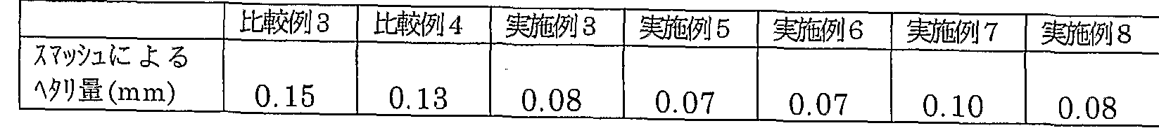
- the smash resistance was measured as follows. An underlay was attached to the blanket trunk, the blanket was stretched over the trunk, and then rotated for a few minutes and tightened again to adjust the compression amount of the blanket to 0.10 mm in the nip. After that, a gauge film having a thickness of 0.5 mm and a size of 50 mm x 50 mm is attached to the surface of the impression cylinder. Rotate the testing machine at a high speed of 100 rpm, stop the testing machine after 100 rpm, and let it recover for 30 minutes. After 30 minutes, the part that was in contact with the gauge film attached to the blanket impression cylinder (A) and the part that was not in contact (B) The amount of settling was measured with a cylinder gauge. (A)-(B) is the amount of hemming by Smash. Table 11 shows the test results.
- Example 7 in which the bottom cloth was made of a woven cloth using vinylon yarn which is a spun yarn by a solvent wet cooling gel spinning method for the warp was used for the smash resistance compared to the comparative example.
- the amount of settling is small.
- Example 8 in which vinylon yarn, which is a spun yarn by a solvent wet cooling gel spinning method, was used for the warp of the bottom fabric and the second fabric, the amount of settling caused by smash was clearly reduced. Therefore, it can be seen that as the number of layers of woven fabric using vinylon yarn, which is a spun yarn obtained by solvent wet cooling gel spinning, is increased as the warp, the amount of smashing decreases.
- the present invention improves the penetration of the binder into the woven fabric by using vinylon yarn which is a spun yarn by a solvent wet cooling gel spinning method for the warp of the woven fabric constituting the reinforcing layer.
- the amount of dusk is small and smash resistance when cutting paper is improved.
- vinylon yarn which is a spun yarn by a solvent wet cooling gel spinning method, is used for the warp of the woven fabric (top fabric) laminated on the lower surface of the surface layer and serving as the support layer, the smoothness is not impaired.
- the adhesiveness to the surface layer is improved, and the effect of the texture on printing can be reduced. Further, according to the configuration of the present invention, it is possible to obtain a planket having excellent durability against repeated compression during high-speed printing, that is, excellent press life.
- the printing planket according to the present invention improves the adhesion between the surface layer serving as the printing surface and the support layer, or between the reinforcing layers, and therefore has excellent durability against repeated compression. It can be used as a blanket for high-speed printing presses.
Landscapes
- Engineering & Computer Science (AREA)
- Textile Engineering (AREA)
- Printing Plates And Materials Therefor (AREA)
Description


Claims
Priority Applications (3)
| Application Number | Priority Date | Filing Date | Title |
|---|---|---|---|
| DE60129773T DE60129773T2 (de) | 2000-04-28 | 2001-04-27 | Verfahren zur herstellung eines drucktuchs |
| EP01926069A EP1195263B1 (en) | 2000-04-28 | 2001-04-27 | A method for manufacturing a blanket for printing |
| US10/018,357 US20030066449A1 (en) | 2000-04-28 | 2001-04-27 | Blanket for printing |
Applications Claiming Priority (4)
| Application Number | Priority Date | Filing Date | Title |
|---|---|---|---|
| JP2000-130205 | 2000-04-28 | ||
| JP2000130205A JP2001310570A (ja) | 2000-04-28 | 2000-04-28 | 印刷用ブランケット |
| JP2000171581A JP2001347771A (ja) | 2000-06-08 | 2000-06-08 | 印刷用ブランケット |
| JP2000-171581 | 2000-06-08 |
Publications (1)
| Publication Number | Publication Date |
|---|---|
| WO2001083236A1 true WO2001083236A1 (en) | 2001-11-08 |
Family
ID=26591174
Family Applications (1)
| Application Number | Title | Priority Date | Filing Date |
|---|---|---|---|
| PCT/JP2001/003744 WO2001083236A1 (en) | 2000-04-28 | 2001-04-27 | Blanket for printing |
Country Status (4)
| Country | Link |
|---|---|
| US (1) | US20030066449A1 (ja) |
| EP (1) | EP1195263B1 (ja) |
| DE (1) | DE60129773T2 (ja) |
| WO (1) | WO2001083236A1 (ja) |
Families Citing this family (5)
| Publication number | Priority date | Publication date | Assignee | Title |
|---|---|---|---|---|
| US6536342B2 (en) * | 2001-06-28 | 2003-03-25 | Macdermid Graphic Arts, Inc. | Low resilience, high ink releasing printing surface |
| AU2003211400A1 (en) * | 2003-02-27 | 2004-09-17 | Kinyosha Co., Ltd. | Rubber blanket for printing |
| JP5250184B2 (ja) * | 2006-01-19 | 2013-07-31 | 株式会社金陽社 | 印刷用ゴムブランケット |
| US10647108B2 (en) * | 2018-04-02 | 2020-05-12 | Canon Kabushiki Kaisha | Image recording apparatus |
| CN110626022B (zh) * | 2019-10-31 | 2021-03-16 | 南通市辉鑫玻璃纤维有限公司 | 一种玻璃纤维纱复合布及其制备方法 |
Citations (2)
| Publication number | Priority date | Publication date | Assignee | Title |
|---|---|---|---|---|
| JPH10272860A (ja) * | 1997-03-31 | 1998-10-13 | Kin Yosha Kk | 印刷用シート状ブランケット |
| JP2000086823A (ja) * | 1998-09-17 | 2000-03-28 | Toyo Tire & Rubber Co Ltd | タイヤ用ゴム組成物 |
Family Cites Families (6)
| Publication number | Priority date | Publication date | Assignee | Title |
|---|---|---|---|---|
| JPS6012959B2 (ja) * | 1976-06-04 | 1985-04-04 | 株式会社エム・エム・テイ | 水棒ロ−ラ−用筒織加湿筒 |
| JPS56164893A (en) * | 1980-05-22 | 1981-12-18 | Nichiyou Keori Kk | Cylindrical cloth for printing water stop |
| JPS6434794A (en) * | 1987-07-30 | 1989-02-06 | Nichiyou Keori Kk | Tubular fabric for dampening roller for printing |
| JP3062302B2 (ja) * | 1991-06-19 | 2000-07-10 | 藤倉ゴム工業株式会社 | オフセット印刷用ブランケットおよびその製造方法 |
| JP2747198B2 (ja) * | 1993-06-07 | 1998-05-06 | 住友ゴム工業株式会社 | 印刷用オフセットブランケット |
| JP3614581B2 (ja) * | 1996-10-08 | 2005-01-26 | 株式会社金陽社 | 印刷用ブランケット |
-
2001
- 2001-04-27 DE DE60129773T patent/DE60129773T2/de not_active Expired - Lifetime
- 2001-04-27 US US10/018,357 patent/US20030066449A1/en not_active Abandoned
- 2001-04-27 EP EP01926069A patent/EP1195263B1/en not_active Expired - Lifetime
- 2001-04-27 WO PCT/JP2001/003744 patent/WO2001083236A1/ja active IP Right Grant
Patent Citations (2)
| Publication number | Priority date | Publication date | Assignee | Title |
|---|---|---|---|---|
| JPH10272860A (ja) * | 1997-03-31 | 1998-10-13 | Kin Yosha Kk | 印刷用シート状ブランケット |
| JP2000086823A (ja) * | 1998-09-17 | 2000-03-28 | Toyo Tire & Rubber Co Ltd | タイヤ用ゴム組成物 |
Non-Patent Citations (1)
| Title |
|---|
| See also references of EP1195263A4 * |
Also Published As
| Publication number | Publication date |
|---|---|
| US20030066449A1 (en) | 2003-04-10 |
| EP1195263A1 (en) | 2002-04-10 |
| DE60129773D1 (de) | 2007-09-20 |
| DE60129773T2 (de) | 2008-04-30 |
| EP1195263A4 (en) | 2006-05-17 |
| EP1195263B1 (en) | 2007-08-08 |
Similar Documents
| Publication | Publication Date | Title |
|---|---|---|
| JP5043141B2 (ja) | 印刷用ゴムブランケット | |
| JP2003527985A (ja) | 非伸長性裏打ち体を備えた可撓性を有する画像転写ブランケット | |
| US20070119320A1 (en) | Printing blanket having improved dynamic thickness stability | |
| WO2001083236A1 (en) | Blanket for printing | |
| EP1810837B1 (en) | Printing rubber blanket | |
| CN111421976B (zh) | 一种油墨转移介质及其制备方法 | |
| JP2907695B2 (ja) | 印刷用ブランケット | |
| US8623774B2 (en) | Printing blanket construction | |
| US6884498B2 (en) | Rubber blanket for offset printing | |
| US7562624B2 (en) | Printing blanket | |
| JP2001310570A (ja) | 印刷用ブランケット | |
| JP2001347771A (ja) | 印刷用ブランケット | |
| JP4172017B2 (ja) | 印刷用ブランケット | |
| JP6903309B2 (ja) | 印刷用ゴムブランケット | |
| JP4264936B2 (ja) | 印刷用ブランケット | |
| JP4927815B2 (ja) | 織物及び印刷用ブランケット | |
| US6207597B1 (en) | Printing blanket | |
| JP2008290275A (ja) | 印刷用ブランケット | |
| JP2863681B2 (ja) | 印刷用ゴムブランケットの製造方法 | |
| JPH11170725A (ja) | 印刷用ブランケット |
Legal Events
| Date | Code | Title | Description |
|---|---|---|---|
| AK | Designated states |
Kind code of ref document: A1 Designated state(s): US |
|
| AL | Designated countries for regional patents |
Kind code of ref document: A1 Designated state(s): DE FR GB IT |
|
| WWE | Wipo information: entry into national phase |
Ref document number: 2001926069 Country of ref document: EP Ref document number: 10018357 Country of ref document: US |
|
| 121 | Ep: the epo has been informed by wipo that ep was designated in this application | ||
| WWP | Wipo information: published in national office |
Ref document number: 2001926069 Country of ref document: EP |
|
| WWG | Wipo information: grant in national office |
Ref document number: 2001926069 Country of ref document: EP |