WO1995005332A1 - Appareil de traitement d'une matiere tissee sous forme de bande - Google Patents
Appareil de traitement d'une matiere tissee sous forme de bande Download PDFInfo
- Publication number
- WO1995005332A1 WO1995005332A1 PCT/JP1994/001369 JP9401369W WO9505332A1 WO 1995005332 A1 WO1995005332 A1 WO 1995005332A1 JP 9401369 W JP9401369 W JP 9401369W WO 9505332 A1 WO9505332 A1 WO 9505332A1
- Authority
- WO
- WIPO (PCT)
- Prior art keywords
- roller
- rollers
- processing
- belt
- fabric
- Prior art date
Links
Classifications
-
- B—PERFORMING OPERATIONS; TRANSPORTING
- B65—CONVEYING; PACKING; STORING; HANDLING THIN OR FILAMENTARY MATERIAL
- B65H—HANDLING THIN OR FILAMENTARY MATERIAL, e.g. SHEETS, WEBS, CABLES
- B65H20/00—Advancing webs
- B65H20/24—Advancing webs by looping or like devices
-
- B—PERFORMING OPERATIONS; TRANSPORTING
- B65—CONVEYING; PACKING; STORING; HANDLING THIN OR FILAMENTARY MATERIAL
- B65H—HANDLING THIN OR FILAMENTARY MATERIAL, e.g. SHEETS, WEBS, CABLES
- B65H23/00—Registering, tensioning, smoothing or guiding webs
- B65H23/04—Registering, tensioning, smoothing or guiding webs longitudinally
- B65H23/32—Arrangements for turning or reversing webs
-
- B—PERFORMING OPERATIONS; TRANSPORTING
- B65—CONVEYING; PACKING; STORING; HANDLING THIN OR FILAMENTARY MATERIAL
- B65H—HANDLING THIN OR FILAMENTARY MATERIAL, e.g. SHEETS, WEBS, CABLES
- B65H27/00—Special constructions, e.g. surface features, of feed or guide rollers for webs
-
- D—TEXTILES; PAPER
- D06—TREATMENT OF TEXTILES OR THE LIKE; LAUNDERING; FLEXIBLE MATERIALS NOT OTHERWISE PROVIDED FOR
- D06B—TREATING TEXTILE MATERIALS USING LIQUIDS, GASES OR VAPOURS
- D06B19/00—Treatment of textile materials by liquids, gases or vapours, not provided for in groups D06B1/00 - D06B17/00
- D06B19/0005—Fixing of chemicals, e.g. dyestuffs, on textile materials
- D06B19/0011—Fixing of chemicals, e.g. dyestuffs, on textile materials by heated air
- D06B19/0017—Fixing of chemicals, e.g. dyestuffs, on textile materials by heated air the textile material passing through a chamber
-
- D—TEXTILES; PAPER
- D06—TREATMENT OF TEXTILES OR THE LIKE; LAUNDERING; FLEXIBLE MATERIALS NOT OTHERWISE PROVIDED FOR
- D06B—TREATING TEXTILE MATERIALS USING LIQUIDS, GASES OR VAPOURS
- D06B23/00—Component parts, details, or accessories of apparatus or machines, specially adapted for the treating of textile materials, not restricted to a particular kind of apparatus, provided for in groups D06B1/00 - D06B21/00
- D06B23/02—Rollers
- D06B23/023—Guiding rollers
-
- B—PERFORMING OPERATIONS; TRANSPORTING
- B65—CONVEYING; PACKING; STORING; HANDLING THIN OR FILAMENTARY MATERIAL
- B65H—HANDLING THIN OR FILAMENTARY MATERIAL, e.g. SHEETS, WEBS, CABLES
- B65H2401/00—Materials used for the handling apparatus or parts thereof; Properties thereof
- B65H2401/10—Materials
-
- B—PERFORMING OPERATIONS; TRANSPORTING
- B65—CONVEYING; PACKING; STORING; HANDLING THIN OR FILAMENTARY MATERIAL
- B65H—HANDLING THIN OR FILAMENTARY MATERIAL, e.g. SHEETS, WEBS, CABLES
- B65H2404/00—Parts for transporting or guiding the handled material
- B65H2404/10—Rollers
- B65H2404/13—Details of longitudinal profile
- B65H2404/132—Details of longitudinal profile arrangement of segments along axis
- B65H2404/1321—Segments juxtaposed along axis
-
- B—PERFORMING OPERATIONS; TRANSPORTING
- B65—CONVEYING; PACKING; STORING; HANDLING THIN OR FILAMENTARY MATERIAL
- B65H—HANDLING THIN OR FILAMENTARY MATERIAL, e.g. SHEETS, WEBS, CABLES
- B65H2408/00—Specific machines
- B65H2408/20—Specific machines for handling web(s)
- B65H2408/21—Accumulators
- B65H2408/217—Accumulators of rollers type, e.g. with at least one fixed and one movable roller
- B65H2408/2173—Accumulators of rollers type, e.g. with at least one fixed and one movable roller the rollers wrapped by the web being rotationally driven otherwise than by web
-
- B—PERFORMING OPERATIONS; TRANSPORTING
- B65—CONVEYING; PACKING; STORING; HANDLING THIN OR FILAMENTARY MATERIAL
- B65H—HANDLING THIN OR FILAMENTARY MATERIAL, e.g. SHEETS, WEBS, CABLES
- B65H2408/00—Specific machines
- B65H2408/20—Specific machines for handling web(s)
- B65H2408/21—Accumulators
- B65H2408/217—Accumulators of rollers type, e.g. with at least one fixed and one movable roller
- B65H2408/2174—Accumulators of rollers type, e.g. with at least one fixed and one movable roller belt or similar device for carrying web through the accumulator
Definitions
- the present invention relates to a band fabric processing apparatus, and more particularly, to dyeing, heat treatment, and refining of a narrow band fabric such as a sheet belt.
- the present invention relates to a processing apparatus used in a step of performing processing such as finishing and finishing. Background art
- the present inventor has proposed a single band woven fabric as disclosed in Japanese Patent Application Laid-Open No. We have proposed a method in which processing is performed by running and passing in a spiral shape (spiral shape) within the processing area.
- ADVANTAGE OF THE INVENTION it becomes possible for a single band-shaped woven fabric to travel and stay in a predetermined processing area for a long time, so that the processing time is shortened and the traveling speed can be drastically increased.
- Productivity has been improved compared to the conventional parallel driving method.
- good results were obtained in which the quality of hue difference, density difference, elongation difference, etc. was stable.
- rubber rollers used for this type of processing include, for example, natural rubber, SBR, NBR, CR chloroprene rubber, IIR Conventionally known rubber materials such as butyl rubber, FPM, urethane rubber and silicon rubber are used. Usually, such a rubber roller is disposed close to the entrance and exit of the heated processing area. The rubber roller is directly affected by the temperature of the processing area, and the higher the processing temperature, the higher the rubber roller.
- the rubber roller with low heat resistance deteriorates the rubber in a short period of time and becomes unusable, and the rubber roller installed at the exit of the heating processing area is pressed Since the band-shaped fabric heated and processed on the rubber surface to be sandwiched is pulled out, the temperature of the rubber roller in particular rises and the rubber deteriorates remarkably.
- the belt-like woven fabric passes at a high speed through a certain portion of an inlet or outlet rubber port provided at an entrance / exit of the heat processing area.
- the temperature of the band-shaped fabric 2 at a position outside the processing area is about 180 ° C, and the passing speed is about 72 mZ. Therefore, the surface temperature of the belt-like woven fabric passing position on the draw-out roller also rises to about 180 ° C. Therefore, as long as the conventional rubber roller is used, the rubber roller takes about several hours to about 10 hours. Was in a state where it could not be used due to wear and deterioration.
- the rubber roller is contaminated by the attachment of dyes and the like, and the contaminants are reattached to the material to be dyed, causing the color of the material to be changed. Or contaminate it.
- the dyeing material to be dyed in order from the lighter dyeing material to the darker color dyeing material. It is necessary to consider the order in which the dyed materials are put in advance, and if the rubber roller needs to be cleaned frequently, and cleaning cannot be performed, the rubber roller should be replaced every two to three months. Decreased work efficiency and increased production costs, such as the necessity of replacement, were inevitable. .
- a plurality of belt-like fabrics are usually run in parallel on a plurality of running rollers arranged at intervals above and below the tank to perform processing.
- the belt-like fabric passes through each roller sequentially from the entrance to the exit.
- the belt-shaped fabric shrinks due to heat, it corresponds to a change in the traveling speed caused by the shrinkage, from the traveling guide port near the entrance to the traveling roller near the exit in the processing area. Although it was passive, it was possible to correspond to the rotation speed of the roller sequentially.
- the conventional running roller has disadvantages.
- the reason is described below.
- the band-shaped fabric shrinks with heating over time, usually for about 90 seconds.
- the belt-like woven fabric travels in the processing area so as not to hinder the contraction of the belt-like woven fabric during the contraction time. Need to be passed.
- the band-like woven fabric becomes significantly large.
- the running area of the right half which runs for about 90 seconds in the first half, is almost all of the contraction of the left half. If the running speed of the belt-like fabric is not increased faster than the second half running area, the first half shrinkage is hindered. Actually, even within the contraction area in the right half of the first half.
- the belt-shaped woven fabric traveling on one traveling roller has the same rotational speed at any traveling position on one roller. Therefore, if this kind of running roller is to be processed in a spiral run, the adjacent belt-shaped fabrics are prevented from freely shrinking due to friction with the roller despite the different shrinkage, resulting in high elongation. The purpose of obtaining a belt-like woven fabric cannot be achieved.
- the problems are the contamination and durability of the rubber roller, which have not been solved by the conventional parallel processing method. Contamination and durability of the discharge outlet, running rollers in the heat treatment area, and these solutions were demanded. Disclosure of the invention
- An object of the present invention is to improve the above-mentioned drawbacks of the prior art, and to reduce the work efficiency by replacing or cleaning the rollers of the introduction / discharge device rollers provided at the entrance and exit of each processing area due to wear, thermal deterioration, etc.
- high-quality products with a uniform, high efficiency fast degree it is an object to provide a processing apparatus that may be produced by (the present invention for achieving the above object, techniques as described below It adopts a configuration.
- the band-shaped fabric is passed through a single processing region in a parallel or spiral shape and passed through the band-shaped fabric.
- a processing device that applies a load under a predetermined tension and speed, the band provided at the entrance and the exit of the band-shaped fabric to the processing region; at least a part of the introduction and discharge roller device of the fabric
- a plurality of metal surface rollers whose surface portions are made of metal, and the plurality of metal surface rollers are arranged such that their surfaces are not in contact with each other. And each of the metal surface rollers can be positively driven and rotated through appropriate driving means.
- a processing apparatus for processing a single band-shaped woven fabric spirally in a single processing region and performing processing on the band-shaped woven fabric under a heating condition
- a plurality of traveling rollers for forming a predetermined guide passage for the band-shaped fabric are provided, and at least a part of the traveling guide rollers is provided.
- the divided roller part is connected and fixed to the rotating shaft of the traveling roller, or attached so that it can freely rotate with respect to the rotating shaft. It is a processing apparatus for a band-shaped woven fabric.
- a driving means for connecting a part of the divided rollers to a rotating shaft and positively rotating the shaft is provided.
- the processing apparatus for the band-shaped woven fabric according to the present invention employs the above-described technical configuration, the rollers at the entrance and the exit of the entrance and exit of the heating processing area are worn by high tension or high heat. Or thermal degradation Not at all. Further, there is no problem in applying the tension necessary for processing of the belt-shaped fabric, and the technical problem which has been a problem in the past is solved. In addition, the effect of the spiral running is remarkably exhibited, thereby improving the working efficiency and increasing the processing speed. In addition to speeding up, the processing conditions in the processing area can be made uniform, so that the quality of the band-shaped woven product can be improved.
- the belt-shaped fabric to be processed is processed by adopting a positively driven traveling roller divided on one axis in the processing region. Since the friction between the running roller and the belt-like fabric based on the heat shrinkage of the belt-like fabric can be eliminated, it is possible to easily process even the belt-like fabric having high shrinkage.
- FIGS. 1 (A) and 1 (B) are views showing the configuration of one specific example of the discharge section of the band-shaped woven fabric processing apparatus according to the present invention.
- FIG. 2 is a side view showing a configuration example of a conventional belt-shaped fabric processing apparatus.
- FIG. 3 is a side view showing the configuration of a specific example of a processing apparatus having a belt-shaped woven fabric introduction portion and a discharge portion according to the present invention in front and behind.
- FIG. 4 is a graph showing a contracted state of the band-shaped woven fabric in the processing apparatus under high temperature of dry heat according to the present invention.
- FIG. 5 is a view showing a configuration of a traveling roller provided with a divided and positive drive mechanism in the band-shaped fabric processing apparatus according to the present invention.
- FIGS. 6 (A) to 6 (C) are diagrams showing an example of the configuration of a divided traveling roller used in the band-shaped woven fabric processing apparatus according to the present invention.
- FIG. 1 is a side view and a front view showing a configuration example of a specific example of a band-shaped fabric processing apparatus 1 according to the present invention.
- a processing apparatus 1 for performing predetermined processing on the band-shaped fabric 2 by passing the band-shaped fabric 2 in a spiral shape a discharge portion 4 of the band-shaped fabric 2 to the processing region 3 is illustrated.
- FIG. 1 (B) is a front view of FIG. 1 (A).
- the roller group 5 (—1 to 5—4) uses a metal surface roller 5 having at least the surface portion made of metal. —;! 5 to 4 are arranged in a non-contact state with each other, and the respective metal surface rollers are positively driven to rotate by appropriate driving means 6. ing.
- the space 3 on the right side of the frame 18 in FIG. 1 (A) constitutes a part of the processing apparatus 1 according to the present invention. It shows a processing area.
- the band-shaped woven fabric 2 which has been subjected to the predetermined processing is once coming out of the area constituting the outlet 4 of the processing area 3, but the lower traveling guide roller in FIG.
- the belt-like woven fabric 2 is bent downward by 1 2, passes through the downward traveling guide roller 13, reaches the upward traveling guide roller 16, and the belt-like woven fabric 2 is turned upside down by the guide roller 16, and
- a metal surface roller 5 composed of a group of rollers 5 (5— ;!
- the above-described belt-shaped woven fabric conveying method is repeated a plurality of times and a predetermined processing is performed, which is called a so-called spiral running method.
- a predetermined processing is performed, which is called a so-called spiral running method.
- Kaisho 6 4 — 3 4 8 4 5 for details.
- the belt-like woven fabric 2 leaves the final running line of the metal surface roller 5-1, and the appropriate guide rollers 15 and 10; It is carried out from the carry-out part 4 of the processing area 3 to the next step via the dancer roller 8 for sensing the tension of the fabric 2 and the guide roller 11.
- each of the metal surface rollers 5-1 to 5-4 is rotated at a predetermined rotational speed by a driving means 6 having an appropriate configuration, and each of the metal surface rollers 5-1 to 5-.
- Each of the rotation shafts 4 is configured to rotate at an equal speed to each other by appropriate power transmission means 17, for example, a chain, a gear, a belt, or the like.
- reference numeral 9 denotes a pressure adjusting device for adjusting the driving motion of the dancer roller 8, which is used, for example, for detecting the tension of a belt-shaped fabric made of a hydraulic cylinder or the like. It is possible.
- FIG. 2 shows a conventional outlet section 4 of the processing area 3.
- FIG. 2 is a view showing a configuration of a nip roller, in which a belt-like fabric 2 pulled out from a guide roller 20 is provided with a tension applying mechanism composed of an appropriate roller group 21 and a dancer roller group 22; It is guided to a nip roller section composed of a guide roller 23 and two rubber rollers 24, and then passes through the nip roller 24, passes through another guide roller 25, and undergoes predetermined processing It is configured to be introduced into the processing area 3.
- the conventional Nipple roller 24 of the processing apparatus 1 has a rubber roller 24 on the surface, and is a pair of rubber rollers 2. 4 and 24 are in close contact with each other under a predetermined pressing force, and the strip-shaped woven fabric 2 as the workpiece is sandwiched between the nip rollers 24 and 24 and conveyed. It has become.
- Such a conventional processing apparatus has the problems described in the prior art, and in order to solve these problems, the present invention basically has the configuration described in the description of FIG. More specifically, the processing region 3 belongs to any one of the dyeing step, the coloring step, the heat treatment step, and the like.
- the apparatus is particularly effective when the processing area is, for example, a thermosol setter which is processed at a dry heat and high temperature.
- the metal surface rollers 5 according to the present invention need to be arranged in a non-contact state with each other, but the interval is not particularly limited and can be arbitrarily determined.
- the number of the metal rollers 5 is not particularly limited, and a slip is generated when the belt-shaped fabric 2 is transported due to a balance between the configuration of the belt-shaped fabric 2 and the surface state of the metal roller 5. It must be designed so that it does not occur.
- the metal surface roller 5 be made entirely of metal.
- only the surface portion of the roller that comes into contact with the belt-like fabric 2 may be made of metal.
- the metal constituting at least the surface of the metal surface roller 5 is preferably provided with a hard chrome jack. Further, the surface of the metal surface roller 5 is preferably It is preferable to be as smooth as possible and preferably mirror-like.
- the belt-shaped woven fabric 2 since the belt-shaped woven fabric 2 has such a configuration, the belt-shaped woven fabric 2 comes into contact with the metal surface roller “5” at many points and on multiple surfaces while being transported through the roller. Even if the front roller 5 has a mirror-like surface, no slip occurs.
- the surface of the metal surface roller 5 is not contaminated, and even if contaminated, it can be easily cleaned.
- the surface of the roller has sufficient abrasion resistance and heat resistance, and can be used semi-permanently.
- the metal surface roller group is maintained in a non-contact state with each other, even if the belt-like woven fabric 2 is partially sewn and connected, the metal-surface roller group is not sewn. It is possible to pass between metal surface rollers without any problem.
- the belt-like fabric 2 since the surface of the metal surface roller 5 is smooth and there is no point contact, the belt-like fabric 2 slightly stretches or contracts between the rollers. It can sufficiently cope with the phenomenon and can contribute to the improvement of the quality because there is no local pressure on the belt-like fabric.
- the roller group including the metal rollers can sufficiently cope with a high load.
- NBR rubber acrylonitrile / butadiene copolymer
- Rubber with a hardness of 80 to 90 is used.
- the roller diameter of the roller is 220 mm.
- the air pressure of the two rollers is 4 kg.
- the load is about 150 kg. It is normal that it is hung.
- the rubber roller to which such a large contact pressure is applied is deformed and locally applies an abnormal force.
- the metal surface roller since there is no deformation of the metal surface roller, after the processing of the belt-shaped woven fabric, There is no concern that the quality and physical properties of the product will be adversely affected.
- the metal surface roller 15 in the processing apparatus according to the present invention has a built-in cooling means for cooling the surface of the metal roller therein.
- the belt-like fabric can be cooled, and it is not necessary to separately provide a device for cooling the belt-like fabric 2 as in the related art.
- the apparatus for processing a belt-like woven fabric according to the present invention has been described as being effective when the belt-like woven fabric 2 is transported in a spiral manner.
- the basic technical idea of the present invention is as follows. Needless to say, the present invention can be applied to the case where the fabric 2 is transported in a parallel manner.
- a press roller that partially presses the belt-like woven fabric 2 against the metal surface roller portion of the introduction and discharge roller device of each of the processing regions 3 or a pretension immediately before the metal surface roller Since the frictional force of the belt-like woven fabric against the metal surface roller increases when the nip roller for imparting the nip roller is provided, it is desirable to provide such a mechanism.
- the band-shaped fabric 2 is run in a single band and spirally runs through one processing region 3.
- the band-shaped fabric 2 is placed in the processing region 3 for a predetermined length or for a predetermined time.
- a plurality of pairs of rollers 51 to 57 and a pair of traveling position shift ports 14-1 and 14-2 are provided, and a part of the traveling plan rollers 51 to 57 has the traveling guide port.
- Belt-like woven fabric provided with driving means 5 1 ′ to 5 7 ′ for positively rotating a part of the rollers 51 to 57 The processing equipment is shown.
- reference numeral 3 denotes various processing areas according to the present invention, and before and after the processing area, an introduction section 9 and an unloading section 4 of the processing area 3 are provided.
- the configuration of the introduction unit and the unloading unit is the same as the configuration of the unloading unit 4 described in the first embodiment in FIG. 1 described above.
- the processing area 3 in FIG. 3 shows a case where the processing area 3 is a thermosol setter, and the band-shaped woven fabric 2 has an introduction section 9, an unloading section 4 and a processing area 3 respectively.
- the spiral running method the material is circulated and predetermined processing is performed.
- an appropriate band-shaped fabric passage 31 is formed by guide rollers 37, 38, 39, 40 and running rollers 51 to 57,
- the traveling rollers 51 to 57 are sandwiched between the heating means 35 and the upper traveling rollers 52, 54, 56 and the lower traveling rollers.
- Row rollers 51, 53, 55, 57 are arranged separately.
- the strip-shaped woven fabric 2 as the workpiece is moved in a zigzag manner between the upper traveling rollers 52, 54, 56 and the lower traveling rollers 51, 53, 55, 57. Then, it undergoes a predetermined heat treatment.
- the belt-shaped woven fabric 2 having a predetermined configuration is run in the region 3 to perform predetermined processing, for example, heat treatment, as described above, the belt-shaped woven fabric 2 force Depending on the type, texture, density, heat treatment temperature, etc., of the fibers constituting the woven fabric 2, the shrinkage behaviors are slightly different from each other.
- the heat shrinkage behavior is related to the time factor. As described above, with the negatively rotated traveling roller, it was not possible to take sufficient measures against the heat shrinkage behavior as described above.
- the present inventors used a thermosol setter as the processing region 3 and used a high elongation-compatible strip H (1.130 kgf elongation of 15%) and a low elongation corresponding strip L ( (1130 K gf elongation at 5%), the heat treatment is performed, and the shrinkage rate of each band-like fabric and the time that the band-like fabric stays in the processing area 3 was measured to obtain the graph shown in FIG.
- the temperature in the processing area 3 was set at about 220 ° C.
- both the strips rapidly shrink in about 10 to 40 seconds after being loaded into the processing area 3, and during this time, the possible shrinkage of each strip was reduced. It was found that the contraction of the band-shaped fabric was completed up to about 80%, and that the band-shaped fabric was contracted in about 90 seconds after the band-shaped fabric was carried into the processing area 3.
- the exit is The discharge rate at It is expected to vary between 68 and 75 m / min due to the tension generated by shrinkage of the woven fabric.
- the driving means 51 ′ to 57 ′ for rotating the running roller are not particularly limited, but for example, a torque motor can be used.
- traveling rollers which of the above-mentioned traveling rollers is actively driven is not particularly limited, and may be a part of the traveling rollers or all the traveling rollers may be actively driven. It may be the one that was made.
- the contraction greatly occurs in consideration of the occurrence of the contraction state. It is desirable that the running roller corresponding to the portion to be produced is positively rotated so that the belt-like fabric is actively fed. In other words, it is not necessary to positively drive the running roller in any of the running rollers, but it is necessary to rotate the band-shaped woven fabric 2 into the processing area 3 for about 10 seconds. During 40 seconds, it was found that it was desirable to positively rotate the running roller 1 so as to forcibly feed the belt-like fabric 2.
- thermosol setter shown in FIG. 3, the present inventors set the traveling rollers 51 to 57 to a passive rotation type as in the past and actually run the belt-shaped fabric in a spiral manner.
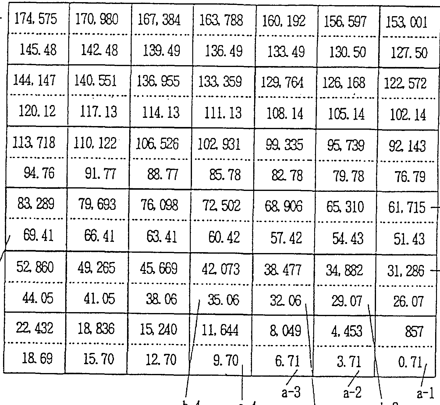
- the traveling time was measured for each traveling roller 51 to 57, and the length (mm) of the belt-like woven fabric passed through the traveling roller up to that point was measured. It is shown in Table 1.
- the predetermined band-shaped fabric 2 is introduced into the thermosol setter 3 shown in Fig. 3 at a speed of about 71.6 mZ by the spiral method into the thermosol setter 3 set at 220 ° C.
- the result of the measurement is shown below.
- the belt-shaped woven fabric 2 was sent into the processing area 3 from the entrance indicated by S in FIG. 3, and was once passed between the running rollers 51-57 in a meandering manner. Later (that is, in the first pass, this step is indicated as column A in Table 1). The strip-shaped woven fabric 2 returns to the traveling roller 51 again and passes between the traveling port rollers 51 to 57 groups. The second pass is made while meandering up and down. This step is designated as column B in Table 1. The specific description of such a spiral running method is carried out in the same manner as that described in the above-mentioned JP-B-64-34845.
- the belt-shaped woven fabric 2 is further circulated in the same processing region 3 five more times (from the same row to the next row), and then discharged to the outside from the outlet E.
- a 1 ⁇ in Table 1 indicates that, when the belt-shaped woven fabric 2 travels the first spiral after passing through the introduction section, the traveling roller provided in the processing region 3
- the elapsed time (seconds) after passing through the entrance S when the vehicle reached the inner roller 51 and the traveling amount (mm) of the belt-shaped fabric 2 were measured.
- the upper part shows the traveling distance (mm) of the band-shaped fabric 2, and the lower part shows the elapsed time (second).
- the column b 4 indicates that the belt-like woven fabric 2 is attached to the traveling roller 54 provided on the upper side of the traveling guide rollers provided in the processing area 3 in the second spiral traveling.
- 5 shows the measurement results of the elapsed time (seconds) after passing through the entrance section S and the travel amount (mm) of the band-shaped woven fabric 2 at the time of arrival.
- the most desirable form is to drive the traveling roller 56 positively. More preferably, the influence of the change in the shrinkage rate is taken into account in view of the change in the shrinkage rate in FIG. It is recommended that the traveling guide rollers 52 and 54 are also driven positively in order to disperse the power. Based on this finding, the present inventors show in Table 2 the results of specific experiments on positive driving speed. Table 2
- Table 2 shows that, in the thermosol setter whose internal set temperature shown in Fig. 3 is set to 230 ° C, the introduction speed of a high elongation sound band-like woven fabric with an elongation of 15% is 7 1.
- the traveling rollers 51, 5 3.5, 5 and 5 7 were passive during the heat treatment.
- the rotation speed of the traveling rollers 52, 54, 56 is reduced by , 53, 55.57 are set to be higher than the negative rotation speed.
- the running rollers have the same diameter.
- the number of revolutions of the roller of the introduction roller device at the entrance of the processing area 3 is set to 91.2 rpm
- the surface speed of the roller is set to 71.6 m
- the processing area 3 The rotation speed of the roller of the discharge unit at the exit of the device is set to 11.0 rpm
- the surface speed of the roller is set to 69.1 m
- the traveling rollers 52, 54 The rotation speed of 56, the voltage of the torque motor is set to 140 V, and the rotation speed is changed in the usual manner.
- the running roller 52 has a rotation speed of 12.0 rpm, The surface speed of the roller is 70.4 m, the running roller 54 has a roller rotation speed of 11.1 O rpm, the surface speed of the roller is 69.7 m, and the running roller For 56, the number of revolutions of the roller was set to 1 13.6 rpm, and the surface speed of the roller was set to 71.4 m.
- the rotation speed of each of the negatively rotating traveling rollers 51, 53, and 55 becomes 0.101 rpm, and the surface speed of the roller is 69.1 m.
- the running roller 57 had a rotation speed of 110.3 rpm and the surface speed of the roller was 69.3 m.
- the heat storage temperature of the belt-shaped woven fabric 2 was 200.2 ° C, and the tension value at the time of the measurement was 78 kg.
- FIG. 5 A specific example will be described as a third embodiment with reference to FIGS. 5 and 6.
- FIG. 5 A specific example will be described as a third embodiment with reference to FIGS. 5 and 6.
- the traveling rollers 51 to 57 is provided with driving means 51 'to 57' for positively rotating the traveling rollers.
- the traveling roller is 1 It has a plurality of divided roller portions on the rotating shaft of the book, and the divided roller portions can be fixed to the rotating shaft of the traveling roller, or can be freely rotatable with respect to the rotating shaft. It is configured so that it is attached as follows. The whole may be rotatable, and if necessary, a part may be connected and fixed to the shaft. In order to cope with the various shrinkage behaviors of various belt-like fabrics, it is desirable to have a mechanism for connecting and fixing as necessary.
- the roller main body is divided into at least two portions 62, 63, and one of the portions, that is, the portion 62 is driven.
- the driving member 17 engaged with the means 51 ′ to 57 ′ is configured so as to be fixedly disposed on the rotating shaft 61 to which it is fixed, while the other portion, that is, the portion of 63 Is provided so as to perform rotatable passive rotation with respect to the rotating shaft 61.
- the belt-shaped woven fabric 2 running according to the spiral running method is configured to pass through the roller portion 62 fixed to the rotating shaft five times, and the roller portion 6 that rotates in a depolarizing manner.
- the band-shaped woven fabric 2 is configured to pass once.
- Such a configuration is merely a specific example in the present invention, and it goes without saying that the range of the mouth to be divided, the number thereof, the number of times of passage of the band-shaped fabric, and the like can be arbitrarily set.
- FIGS. 6 (A) to 6 (C) show examples of the division of the positive rotation roller according to the second embodiment of the present invention
- FIG. FIG. 6 (B) shows that the roller is divided into three parts, the central part 64 is fixed to the rotating shaft 61, and the parts 65 on both sides are matched.
- 6 6 is a negative rotation roller.
- the division length of this mouthpiece can be set arbitrarily.
- Fig. 6 (C) shows the roller divided into 5 parts and the right end 6 Is fixed to the rotating shaft 61, and the remaining portions 68 to 71 are depolarized rotating rollers.
- the split length of each part of the roller is arbitrarily set.
- a roller shown in FIG. 6 (C) is adopted as the traveling guide roller 56, and a spiral traveling belt is provided on the fixed portion 67. It is desirable to set the roller width so that the first stage and the second stage of the fabric 2 can pass through.
- the abrasion resistance and heat resistance of the roller are completely and semi-permanent durability is obtained, and the practicality of the spiral running system is established.
- the divided running roller and positively driving it it is possible to respond to any shrinkage behavior of the band-like fabric, completely solving the conventional problems, and It is possible to provide an apparatus for processing and processing strip-shaped fabrics capable of high-speed processing, and to efficiently and inexpensively produce strip-shaped fabrics that are processed and have a uniform value in the quality of the strip-shaped fabric. Becomes possible.
- the present invention for example, in the case of sheet-belt rubbing, it is possible to process a high elongation product of 17% or more at 110 kgf, which could not be processed at all by the spiral running method. In addition, it is possible to process high elongation products as high as 22%, so that the processable range can be expanded.
Description


Claims
Priority Applications (7)
| Application Number | Priority Date | Filing Date | Title |
|---|---|---|---|
| DE69418693T DE69418693T2 (de) | 1993-08-18 | 1994-08-18 | Apparat zum behandeln von gurtartigem gewebematerial |
| EP94924388A EP0666233B1 (en) | 1993-08-18 | 1994-08-18 | Belt type woven material processing apparatus |
| CA002146540A CA2146540A1 (en) | 1993-08-18 | 1994-08-18 | Belt type woven material processing apparatus |
| KR1019950701469A KR100338061B1 (ko) | 1993-08-18 | 1994-08-18 | 대상직물의가공처리장치 |
| NO951435A NO951435L (no) | 1993-08-18 | 1995-04-12 | Apparat for behandling av töybånd |
| US08/807,195 US6041989A (en) | 1993-08-18 | 1997-02-27 | Apparatus for the treatment of cloth strip |
| NO971835A NO304222B1 (no) | 1993-08-18 | 1997-04-21 | Apparat for behandling av t°ybÕnd |
Applications Claiming Priority (2)
| Application Number | Priority Date | Filing Date | Title |
|---|---|---|---|
| JP5204207A JP2654907B2 (ja) | 1993-08-18 | 1993-08-18 | 帯状織物の加工処理装置 |
| JP5/204207 | 1993-08-18 |
Related Child Applications (1)
| Application Number | Title | Priority Date | Filing Date |
|---|---|---|---|
| US41174195A Continuation | 1993-08-18 | 1995-04-02 |
Publications (1)
| Publication Number | Publication Date |
|---|---|
| WO1995005332A1 true WO1995005332A1 (fr) | 1995-02-23 |
Family
ID=16486611
Family Applications (1)
| Application Number | Title | Priority Date | Filing Date |
|---|---|---|---|
| PCT/JP1994/001369 WO1995005332A1 (fr) | 1993-08-18 | 1994-08-18 | Appareil de traitement d'une matiere tissee sous forme de bande |
Country Status (9)
| Country | Link |
|---|---|
| US (1) | US6041989A (ja) |
| EP (2) | EP0843038B1 (ja) |
| JP (1) | JP2654907B2 (ja) |
| KR (1) | KR100338061B1 (ja) |
| CA (2) | CA2146540A1 (ja) |
| DE (2) | DE69418693T2 (ja) |
| ES (2) | ES2132421T3 (ja) |
| NO (2) | NO951435L (ja) |
| WO (1) | WO1995005332A1 (ja) |
Families Citing this family (4)
| Publication number | Priority date | Publication date | Assignee | Title |
|---|---|---|---|---|
| EP0942090B1 (en) * | 1996-09-13 | 2003-05-14 | Kikuchi Web Tech Co., Ltd. | Band-like cloth processing apparatus |
| KR100902983B1 (ko) * | 2006-05-11 | 2009-06-15 | 가부시끼가이샤 도시바 | 지엽류 분리 취출 장치 |
| WO2016151701A1 (ja) * | 2015-03-20 | 2016-09-29 | Jdc株式会社 | スリット帯板の巻取り張力付与装置 |
| CN108315925A (zh) * | 2018-01-30 | 2018-07-24 | 大源无纺新材料(天津)有限公司 | 一种新型无纺布后处理涂覆工艺 |
Citations (4)
| Publication number | Priority date | Publication date | Assignee | Title |
|---|---|---|---|---|
| JPS5795415A (en) * | 1980-12-05 | 1982-06-14 | Toray Ind Inc | Transfer of resin sheet |
| JPS5892245U (ja) * | 1981-12-17 | 1983-06-22 | 昭和アルミニウム株式会社 | 複写機用冷却ロ−ラ |
| JPS6434845A (en) * | 1987-07-27 | 1989-02-06 | Kikuchi Kogyo | Device for displacing running position of narrow width web |
| JPH01162451U (ja) * | 1988-04-27 | 1989-11-13 |
Family Cites Families (13)
| Publication number | Priority date | Publication date | Assignee | Title |
|---|---|---|---|---|
| DE169016C (ja) * | ||||
| DE1089720B (de) * | 1959-07-25 | 1960-09-29 | Masch Fabriken Tillm Gerber So | Einrichtung zum Fuehren von bandfoermigem Gut |
| DE1604248A1 (de) * | 1965-05-20 | 1970-08-27 | Winkler Fallert & Co Maschf | Kuehl- und Heizwalze |
| US4055612A (en) * | 1972-02-15 | 1977-10-25 | Peter Zimmer | Treating of travelling webs |
| US3964658A (en) * | 1974-09-04 | 1976-06-22 | Edwards Edwin L | Roller replacing |
| JPS5892245A (ja) * | 1981-11-28 | 1983-06-01 | Mitsubishi Electric Corp | 内部整合型トランジスタ素子 |
| US4545544A (en) * | 1982-09-10 | 1985-10-08 | Figge International, Inc. | Fabric handling apparatus and method |
| US4825517A (en) * | 1984-11-15 | 1989-05-02 | Phillips Petroleum Company | Apparatus for drawing and interlacing |
| JPS61217416A (ja) * | 1985-03-19 | 1986-09-27 | Yokohama Rubber Co Ltd:The | 高温押出し物の冷却搬送装置 |
| JPH01134845A (ja) * | 1987-11-20 | 1989-05-26 | Hitachi Ltd | 自動非点収差補正装置 |
| JP2563193B2 (ja) * | 1987-12-18 | 1996-12-11 | 松下電送株式会社 | ファクシミリ装置 |
| DE3833733A1 (de) * | 1988-10-04 | 1990-04-05 | Agfa Gevaert Ag | Verfahren und vorrichtung zur koppelung von verschiedenartigen maschinen zur verarbeitung von bandfoermigen, lichtempfindlichen fotografischen materialien |
| DE9300761U1 (ja) * | 1993-01-21 | 1993-03-11 | Stang Forschungs- Und Entwicklungsgesellschaft D.B.R., 5550 Bernkastel-Kues, De |
-
1993
- 1993-08-18 JP JP5204207A patent/JP2654907B2/ja not_active Expired - Fee Related
-
1994
- 1994-08-18 DE DE69418693T patent/DE69418693T2/de not_active Expired - Fee Related
- 1994-08-18 ES ES94924388T patent/ES2132421T3/es not_active Expired - Lifetime
- 1994-08-18 WO PCT/JP1994/001369 patent/WO1995005332A1/ja active IP Right Grant
- 1994-08-18 ES ES97121998T patent/ES2176597T3/es not_active Expired - Lifetime
- 1994-08-18 EP EP97121998A patent/EP0843038B1/en not_active Expired - Lifetime
- 1994-08-18 EP EP94924388A patent/EP0666233B1/en not_active Expired - Lifetime
- 1994-08-18 KR KR1019950701469A patent/KR100338061B1/ko not_active IP Right Cessation
- 1994-08-18 CA CA002146540A patent/CA2146540A1/en not_active Abandoned
- 1994-08-18 DE DE69430592T patent/DE69430592T2/de not_active Expired - Fee Related
-
1995
- 1995-04-12 NO NO951435A patent/NO951435L/no unknown
-
1996
- 1996-09-13 CA CA002205434A patent/CA2205434C/en not_active Expired - Fee Related
-
1997
- 1997-02-27 US US08/807,195 patent/US6041989A/en not_active Expired - Fee Related
- 1997-04-21 NO NO971835A patent/NO304222B1/no unknown
Patent Citations (4)
| Publication number | Priority date | Publication date | Assignee | Title |
|---|---|---|---|---|
| JPS5795415A (en) * | 1980-12-05 | 1982-06-14 | Toray Ind Inc | Transfer of resin sheet |
| JPS5892245U (ja) * | 1981-12-17 | 1983-06-22 | 昭和アルミニウム株式会社 | 複写機用冷却ロ−ラ |
| JPS6434845A (en) * | 1987-07-27 | 1989-02-06 | Kikuchi Kogyo | Device for displacing running position of narrow width web |
| JPH01162451U (ja) * | 1988-04-27 | 1989-11-13 |
Non-Patent Citations (1)
| Title |
|---|
| See also references of EP0666233A4 * |
Also Published As
| Publication number | Publication date |
|---|---|
| KR100338061B1 (ko) | 2002-10-09 |
| CA2205434C (en) | 2000-11-07 |
| JPH0753103A (ja) | 1995-02-28 |
| EP0666233B1 (en) | 1999-05-26 |
| DE69418693D1 (de) | 1999-07-01 |
| JP2654907B2 (ja) | 1997-09-17 |
| DE69418693T2 (de) | 1999-10-07 |
| ES2132421T3 (es) | 1999-08-16 |
| EP0843038A1 (en) | 1998-05-20 |
| US6041989A (en) | 2000-03-28 |
| EP0843038B1 (en) | 2002-05-08 |
| NO951435L (no) | 1995-06-14 |
| DE69430592T2 (de) | 2002-11-07 |
| NO971835L (no) | 1995-06-14 |
| ES2176597T3 (es) | 2002-12-01 |
| CA2205434A1 (en) | 1998-03-14 |
| NO971835D0 (no) | 1997-04-21 |
| DE69430592D1 (de) | 2002-06-13 |
| NO304222B1 (no) | 1998-11-16 |
| EP0666233A1 (en) | 1995-08-09 |
| EP0666233A4 (en) | 1996-03-06 |
| CA2146540A1 (en) | 1995-02-23 |
| NO951435D0 (no) | 1995-04-12 |
Similar Documents
| Publication | Publication Date | Title |
|---|---|---|
| US5546856A (en) | Method for finishing a continuous sheet of paper | |
| WO1995005332A1 (fr) | Appareil de traitement d'une matiere tissee sous forme de bande | |
| AU699803B2 (en) | Belt-type woven material processing apparatus | |
| KR19980701686A (ko) | 플라스틱 필름의 압연장치 | |
| US5706995A (en) | Apparatus for the treatment of cloth strip with metal-surface rollers | |
| US3237316A (en) | Apparatus for drying continuous lengths of film or paper or the like | |
| US6203307B1 (en) | System for finishing surface of a web of paper having an improved continuous finishing belt | |
| EP3868898B1 (en) | Machine for finishing hides | |
| US1981411A (en) | Annealing and pickling plant | |
| US6007921A (en) | Continuous finishing belt capable of finishing surface of a web of paper | |
| JPH061380Y2 (ja) | ゴムシートの連続加硫機 | |
| JP2923213B2 (ja) | ロールアイロナー | |
| GB1577686A (en) | Continuous treatment of cloth material | |
| US662910A (en) | Apparatus for applying coatings. | |
| US4029201A (en) | Conveyor apparatus | |
| JPH0576934A (ja) | テンシヨンローラレベラ | |
| JP5113452B2 (ja) | 無端ベルトの製造方法及び無端ベルトの研磨装置 | |
| JP5257664B2 (ja) | 転写装置、及びこれを備えた画像形成装置 | |
| US6116794A (en) | Apparatus for cooling a thermally processed material | |
| US1002473A (en) | Machine for laundrying. | |
| US914965A (en) | Ironing-machine. | |
| JPH10316287A (ja) | 布帛の搬送装置 | |
| JPH0679734B2 (ja) | 耐スリツプ性の優れた搬送ロ−ル | |
| JPH0567368U (ja) | 紙面艶出機 | |
| JPH03255874A (ja) | 回転円筒型処理装置 |
Legal Events
| Date | Code | Title | Description |
|---|---|---|---|
| AK | Designated states |
Kind code of ref document: A1 Designated state(s): CA KR NO US |
|
| AL | Designated countries for regional patents |
Kind code of ref document: A1 Designated state(s): AT BE CH DE DK ES FR GB GR IE IT LU MC NL PT SE |
|
| ENP | Entry into the national phase |
Ref document number: 1995 411741 Country of ref document: US Date of ref document: 19950406 Kind code of ref document: A |
|
| WWE | Wipo information: entry into national phase |
Ref document number: 2146540 Country of ref document: CA Ref document number: 1994924388 Country of ref document: EP |
|
| 121 | Ep: the epo has been informed by wipo that ep was designated in this application | ||
| WWP | Wipo information: published in national office |
Ref document number: 1994924388 Country of ref document: EP |
|
| ENP | Entry into the national phase |
Ref document number: 1997 807195 Country of ref document: US Date of ref document: 19970227 Kind code of ref document: A |
|
| WWG | Wipo information: grant in national office |
Ref document number: 1994924388 Country of ref document: EP |