EP0843038B1 - Apparatus for the treatment of a single cloth strip - Google Patents
Apparatus for the treatment of a single cloth strip Download PDFInfo
- Publication number
- EP0843038B1 EP0843038B1 EP97121998A EP97121998A EP0843038B1 EP 0843038 B1 EP0843038 B1 EP 0843038B1 EP 97121998 A EP97121998 A EP 97121998A EP 97121998 A EP97121998 A EP 97121998A EP 0843038 B1 EP0843038 B1 EP 0843038B1
- Authority
- EP
- European Patent Office
- Prior art keywords
- cloth strip
- conveying rollers
- treatment
- roller
- cloth
- Prior art date
- Legal status (The legal status is an assumption and is not a legal conclusion. Google has not performed a legal analysis and makes no representation as to the accuracy of the status listed.)
- Expired - Lifetime
Links
Images


Classifications
-
- B—PERFORMING OPERATIONS; TRANSPORTING
- B65—CONVEYING; PACKING; STORING; HANDLING THIN OR FILAMENTARY MATERIAL
- B65H—HANDLING THIN OR FILAMENTARY MATERIAL, e.g. SHEETS, WEBS, CABLES
- B65H20/00—Advancing webs
- B65H20/24—Advancing webs by looping or like devices
-
- B—PERFORMING OPERATIONS; TRANSPORTING
- B65—CONVEYING; PACKING; STORING; HANDLING THIN OR FILAMENTARY MATERIAL
- B65H—HANDLING THIN OR FILAMENTARY MATERIAL, e.g. SHEETS, WEBS, CABLES
- B65H23/00—Registering, tensioning, smoothing or guiding webs
- B65H23/04—Registering, tensioning, smoothing or guiding webs longitudinally
- B65H23/32—Arrangements for turning or reversing webs
-
- B—PERFORMING OPERATIONS; TRANSPORTING
- B65—CONVEYING; PACKING; STORING; HANDLING THIN OR FILAMENTARY MATERIAL
- B65H—HANDLING THIN OR FILAMENTARY MATERIAL, e.g. SHEETS, WEBS, CABLES
- B65H27/00—Special constructions, e.g. surface features, of feed or guide rollers for webs
-
- D—TEXTILES; PAPER
- D06—TREATMENT OF TEXTILES OR THE LIKE; LAUNDERING; FLEXIBLE MATERIALS NOT OTHERWISE PROVIDED FOR
- D06B—TREATING TEXTILE MATERIALS USING LIQUIDS, GASES OR VAPOURS
- D06B19/00—Treatment of textile materials by liquids, gases or vapours, not provided for in groups D06B1/00 - D06B17/00
- D06B19/0005—Fixing of chemicals, e.g. dyestuffs, on textile materials
- D06B19/0011—Fixing of chemicals, e.g. dyestuffs, on textile materials by heated air
- D06B19/0017—Fixing of chemicals, e.g. dyestuffs, on textile materials by heated air the textile material passing through a chamber
-
- D—TEXTILES; PAPER
- D06—TREATMENT OF TEXTILES OR THE LIKE; LAUNDERING; FLEXIBLE MATERIALS NOT OTHERWISE PROVIDED FOR
- D06B—TREATING TEXTILE MATERIALS USING LIQUIDS, GASES OR VAPOURS
- D06B23/00—Component parts, details, or accessories of apparatus or machines, specially adapted for the treating of textile materials, not restricted to a particular kind of apparatus, provided for in groups D06B1/00 - D06B21/00
- D06B23/02—Rollers
- D06B23/023—Guiding rollers
-
- B—PERFORMING OPERATIONS; TRANSPORTING
- B65—CONVEYING; PACKING; STORING; HANDLING THIN OR FILAMENTARY MATERIAL
- B65H—HANDLING THIN OR FILAMENTARY MATERIAL, e.g. SHEETS, WEBS, CABLES
- B65H2401/00—Materials used for the handling apparatus or parts thereof; Properties thereof
- B65H2401/10—Materials
-
- B—PERFORMING OPERATIONS; TRANSPORTING
- B65—CONVEYING; PACKING; STORING; HANDLING THIN OR FILAMENTARY MATERIAL
- B65H—HANDLING THIN OR FILAMENTARY MATERIAL, e.g. SHEETS, WEBS, CABLES
- B65H2404/00—Parts for transporting or guiding the handled material
- B65H2404/10—Rollers
- B65H2404/13—Details of longitudinal profile
- B65H2404/132—Details of longitudinal profile arrangement of segments along axis
- B65H2404/1321—Segments juxtaposed along axis
-
- B—PERFORMING OPERATIONS; TRANSPORTING
- B65—CONVEYING; PACKING; STORING; HANDLING THIN OR FILAMENTARY MATERIAL
- B65H—HANDLING THIN OR FILAMENTARY MATERIAL, e.g. SHEETS, WEBS, CABLES
- B65H2408/00—Specific machines
- B65H2408/20—Specific machines for handling web(s)
- B65H2408/21—Accumulators
- B65H2408/217—Accumulators of rollers type, e.g. with at least one fixed and one movable roller
- B65H2408/2173—Accumulators of rollers type, e.g. with at least one fixed and one movable roller the rollers wrapped by the web being rotationally driven otherwise than by web
-
- B—PERFORMING OPERATIONS; TRANSPORTING
- B65—CONVEYING; PACKING; STORING; HANDLING THIN OR FILAMENTARY MATERIAL
- B65H—HANDLING THIN OR FILAMENTARY MATERIAL, e.g. SHEETS, WEBS, CABLES
- B65H2408/00—Specific machines
- B65H2408/20—Specific machines for handling web(s)
- B65H2408/21—Accumulators
- B65H2408/217—Accumulators of rollers type, e.g. with at least one fixed and one movable roller
- B65H2408/2174—Accumulators of rollers type, e.g. with at least one fixed and one movable roller belt or similar device for carrying web through the accumulator
Definitions
- the present invention relates to an apparatus for the treatment of a single cloth strip, more specifically to an apparatus used in a process for carrying out the dyeing, heat treatment, scouring, finishing or the like of a narrow cloth strip such as a seat belt material.
- a narrow cloth strip to be used as a safety belt a seat belt or a sling is subjected to a treatment such as dyeing, heat treatment, scouring or finishing, a plurality of cloth strips run continuously in a side-by-side manner, i.e., in parallel with, through a series of processes, which normally start the supply of greige fabric and include scouring, dyeing, rinsing, drying, heat-setting and the application of a surface agent.
- the present inventors proposed a treatment method as disclosed in Japanese Unexamined Patent Publication (Kokai) No. 1-34845 "Apparatus for Shifting Running Position of Narrow Width Fabric" wherein a single cloth strip runs along a spiral path in a predetermined treatment zone.
- this proposal it is possible to keep a longer length of cloth strip in the predetermined treatment zone, whereby it is possible to shorten the treatment time and remarkably increase the running speed.
- the productivity has been improved compared with the conventional parallel running system.
- differences in hue, color density, elongation or others have been reduced to stabilize the product quality.
- the cloth strip gradually contracts due to heat during the first 90 seconds.
- the thermal treatment in which the cloth strip runs along a spiral path to give the strip a high elongation it is necessary to allow the cloth strip passing the thermal treatment to contract during the contraction period.
- Document DE 93 00 761U discloses an apparatus according to the preamble of claim 1.
- the object of the present invention is to solve the above drawbacks in the prior art and provide a thermal treatment apparatus capable of producing a high elongation product by preventing the contraction of a cloth strip from being disturbed during the treatment, and of treating cloth strips having wide range elongations, whereby the products having uniform high grade qualities are effectively obtainable at a high rate.
- the present invention has the following constitution:
- a first aspect of the present invention is an apparatus for treating a single cloth strip wherein the cloth strip is subjected to a treatment in a heated state while running along a spiral path through a treatment zone, wherein a plurality of conveying rollers are provided in the treatment zone for forming a predetermined path for the cloth strip; each one of at least a part of the conveying rollers comprises a plurality of roller sections and one or some of said roller sections of said conveying rollers being fixedly mounted on a common positively driven rotary shaft, while the remaining roller sections thereof, other than said roller sections fixedly coupled to said shaft, are freely rotatable relative to the rotary shaft.
- the apparatus for treating a cloth strip according to the present invention has the abovesaid constitution, the wear and deterioration of the introduction/withdrawal rollers at the entrance and exit zones of the thermal treatment zone due to high tension and high temperature are completely avoided.
- the drawbacks in the prior art can be solved and the remarkable effects due to the spiral running, such as an improvement in working efficiency, an acceleration of the treating rate or the equalization of treatment conditions in the treatment zone are obtainable.
- an improvement in the quality of cloth strip is achievable.
- conveying rollers each are divided into a plurality of sections and mounted onto the positively driven common shaft, are used in the treatment zone, it is possible to eliminate friction between the conveying roller and the cloth strip caused by thermal contraction of the cloth strip to be treated, whereby the treatment can be easily carried out even on a highly shrinkable cloth strip.
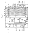
- the first aspect of the present invention is an apparatus 1 for treating a single cloth strip 2 while running the same through a treatment zone 3 along a spiral path as shown in Fig. 1, wherein a plurality of conveying rollers 51 through 57 and a plurality of pairs of shifting rollers 14-1 and 14-2 are provided for forming a predetermined path 31, and drive means 51' through 57' are also provided for positively rotating at least part of the conveying rollers 51 through 57.
- the treatment zone 3 in which one of various treatments is carried out on the cloth strip has an entrance part 9' and an exit part 4 on the front and rear sides thereof, respectively, having the following structure:
- a group of rollers 5 (5-1 trough 5-4) are arranged in a non-contacted state with each other. These rollers are positively driven to rotate.
- the cloth strip 2 emerges from the main treatment zone 3, it is introduced into the exit part 4 via a downward guide roller while being deflected downward and via another upward guide roller, at which it reverses the running direction upward and reaches the group of the rollers 5 (5-1 through 5-4).
- the cloth strip 2 is twisted at 90° via a pair of shifting rollers 14-1 and 14-2 and reaches another downward guide roller while being shifted at a predetermined distance in the axial direction of the downward guide roller.
- the close strip 2 reverses the running direction downward to the upward guide roller again and returns to the downward guide roller while shifting the running position thereon via the pair of shifting rollers 14-1, 14-2.
- the cloth strip 2 is withdrawn, away from the final roller 5-1, from the exit part 4 of the main treatment zone 3 into the next process via suitable guide rollers and a dancer roller for detecting a tension of the cloth strip 2.
- Fig. 1 illustrates a thermosol setter wherein the cloth strip 2 is subjected to a predetermined treatment in the entrance part 9', exit part 4 and main treatment zone 3 while running through the respective zones along a spiral path.
- the running path 31 is formed by deflection rollers 37, 38, 39, 40 and the conveying rollers 51 through 57.
- the conveying rollers 51 through 57 are grouped into upper conveying rollers 52, 54 and 56 and lower conveying rollers 51, 53, 55 and 57 with an intervening heating means 57 therebetween.
- the cloth strip to be treated runs between the upper conveying rollers 52, 54 and 56 and the lower conveying rollers 51, 53, 55 and 57 in a zigzag manner and subjected to a predetermined treatment.
- the cloth strip 2 When the cloth strip 2 is subjected to the predetermined treatment such as heat treatment while running through the above treatment zone 3, the cloth strip exhibits a thermal contraction behavior which is delicately different from that of others in accordance with the fiber composition, weave structure or yarn density of the cloth strip 2, thermal treatment temperature or others, as described before. Since such thermal behavior is also related to a time factor, it is impossible to take a proper countermeasure to such thermal behavior by passively rotating the conveying rollers of the conventional system.
- the predetermined treatment such as heat treatment while running through the above treatment zone 3
- the cloth strip exhibits a thermal contraction behavior which is delicately different from that of others in accordance with the fiber composition, weave structure or yarn density of the cloth strip 2, thermal treatment temperature or others, as described before. Since such thermal behavior is also related to a time factor, it is impossible to take a proper countermeasure to such thermal behavior by passively rotating the conveying rollers of the conventional system.
- the present inventors made a study on the relationship between the contraction of cloth strip and the dwelling time of a cloth strip in the treatment zone 3 of thermosol setter while using a cloth strip H (having 15% elongation at 1130 kgf) in a field requiring a high elongation and a cloth strip L (having 5% elongation at 1130 kgf), in a field requiring a low elongation, and obtained a graph shown in Fig. 2.
- the temperature in the treatment zone 3 is maintained at about 220 °C.
- both of the cloth strips rapidly contract within about 10 seconds through 40 seconds after being introduced into the treatment zone 3; i.e., about 80% of the expected maximum contraction was reached in this period, and the contraction was completed within about 90 seconds.
- a torque motor is preferably used as drive means 51' through 57' used for rotating the conveying rollers.
- conveying rollers are to be positively driven; i.e., either part thereof or all thereof may be positively driven.
- the conveying rollers provided in an area wherein the contraction remarkably occurs are positively rotated while taking the amount of contraction into consideration. That is, it was found that any of the conveying rollers do not need to be rotated in a positive manner in about 10 seconds after the introduction of cloth strip 2 into the treatment zone 3, but is preferably to positively rotate the rollers in a period of about 10 seconds through 40 seconds so that the cloth strip 2 is forcibly conveyed.
- thermosol setter shown in Fig. 1, wherein the conveying rollers 51 through 57 are passively rotated in the conventional manner so that the cloth strip runs along a spiral path. Periods (sec) required for the cloth strip to reach the respective rollers 51 through 57 and lengths (mm) of the cloth strip passing over the respective rollers for these periods were measured. Results thereof were listed in Table 1.
- the above table shows the results of measurement when the cloth strip 1 was introduced into the thermosol setter 3 of Fig. 1, wherein the internal temperature is maintained at 220 °C, at a speed of about 71.6 m/min.
- the cloth strip 2 was supplied to the treatment zone 3 from an entrance part S in Fig. 1 and passed over the group of conveying rollers 51 through 57 in a meandering manner in the upward and downward directions (this is called as a first passage and referred to as series A in Table 1). Thereafter, the cloth strip 2 returned to the initial conveying roller 51 and a second passage was repeated between the conveying rollers 51 through 57 in a similar manner as the first passage. This is referred to as series B in Table 1.
- the cloth strip 2 is circulated through the same treatment zone 3 while similarly repeating the above path a further five times (series C through series F) and was withdrawn from an exit part E.
- column b-4 shows a period (seconds) required for the cloth strip 2 to reach the second conveying roller 54 provided in the upper area of the treatment zone 3 after passing over the entrance part S and the length (mm) thereof moved during this period.
- Table 1 it is apparent that the position of a cloth strip 2 ten seconds after introduction into the treatment zone 3 is at the conveying roller 55 during the first spiral passage, and that a position corresponding to 40 seconds is at the conveying roller 56 during the second spiral passage. As stated before, a remarkable contraction occurs in the short period between 10 seconds and 40 seconds.
- the conveying roller 56 is preferably positively driven and, more preferably, the conveying rollers 52 and 54 are also positively driven for the purpose of distributing the influence of contraction while taking into account the Variation of contraction shown in Fig. 2.
- the rotational speed of an introduction roller in the entrance part of the treatment zone 3 is set at 91.2 rpm so that the peripheral speed thereof is 71.6m/min, while a withdrawal roller in the exit part of the treatment zone 3 is set at 110.0 rpm so that the peripheral speed thereof is 69.1 m/min.
- the conveying rollers 52, 54, 56 were driven by torque motors set at 140 V and the rotational speeds thereof were adjusted in a usual manner so that the conveying roller 52 is driven at the rotational speed of 112.0 rpm and the peripheral speed of 70.4 m/min; the conveying roller 54 at 111.0 rpm and 69.7 m/min; and the conveying roller 56 at 113.6 rpm and 71.4 m/min.
- the passive conveying rollers 51, 53 and 55 were driven at a rotational speed of 110.0 rpm and a peripheral speed of 69.1 m/min but the conveying roller 57 was driven at a rotational speed of 110.3 rpm and a peripheral speed of 69.3 m/min.
- the temperature of cloth strip 2 was 200.2 °C and the tension thereof was 78 kg during the measurement.
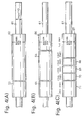
- the conveying rollers 51 through 57 are structured so that a plurality of divided roller sections are mounted onto a common rotary shaft in a fixed manner or a freely rotatable manner relative to the shaft. All the divided roller sections may be rotatable, while some of them may be fixedly coupled to the shaft if necessary. In order to conform to various contraction behaviors of the cloth strips, the latter mechanism is preferable.
- the conveying roller 52 is divided into at least two sections 62, 63, and the one section 62 is fixedly mounted to the rotary shaft 61, to which is fastened a driving member 17 engaged with one of driving means 51' through 57'.
- the other section 63 is mounted to the rotary shaft 61 in a passively rotatable manner.
- the conveying roller 52 is structured so that the cloth strip 2 running along a spiral path is made to pass five times over the roller section 62 fixed to the rotary shaft, while passing only once over the passively rotated roller section 63.
- Such a structure is one of embodiments of the conveying roller according to the present invention, in which the divided areas or the number of the conveying rollers, or the times the cloth strip passes over the roller can be optionally selected.
- Figs. 4(A) through 4(C) illustrate other embodiments of the conveying roller according to the present invention.
- Fig. 4(A) coincides with the above embodiment shown in Fig. 3.
- Fig. 4(B) the conveying roller is divided into three sections wherein a middle section 64 is fixedly mounted to the rotary shaft 61 and side sections 65, 66 are structured as passively rotatable rollers. In this connection, the divided lengths of the conveying roller may be optionally selected.
- the conveying roller is divided into five sections wherein the right end section 67 is fixedly mounted to the rotary shaft 61 and the remaining sections 68 through 71 are passively rotatable rollers.
- the lengths of the respective sections can be optionally selected.
- cloth strips including both lower and higher elongation strips can be treated without any limitations.
- a seat belt webbing of a high elongation type having an elongation of more than 17% and reaching 22% under a load of 11081 N (1130 kgf), can be treated.
Applications Claiming Priority (4)
| Application Number | Priority Date | Filing Date | Title |
|---|---|---|---|
| JP5204207A JP2654907B2 (ja) | 1993-08-18 | 1993-08-18 | 帯状織物の加工処理装置 |
| JP20420793 | 1993-08-18 | ||
| JP204207/93 | 1993-08-18 | ||
| EP94924388A EP0666233B1 (en) | 1993-08-18 | 1994-08-18 | Belt type woven material processing apparatus |
Related Parent Applications (1)
| Application Number | Title | Priority Date | Filing Date |
|---|---|---|---|
| EP94924388A Division EP0666233B1 (en) | 1993-08-18 | 1994-08-18 | Belt type woven material processing apparatus |
Publications (2)
| Publication Number | Publication Date |
|---|---|
| EP0843038A1 EP0843038A1 (en) | 1998-05-20 |
| EP0843038B1 true EP0843038B1 (en) | 2002-05-08 |
Family
ID=16486611
Family Applications (2)
| Application Number | Title | Priority Date | Filing Date |
|---|---|---|---|
| EP97121998A Expired - Lifetime EP0843038B1 (en) | 1993-08-18 | 1994-08-18 | Apparatus for the treatment of a single cloth strip |
| EP94924388A Expired - Lifetime EP0666233B1 (en) | 1993-08-18 | 1994-08-18 | Belt type woven material processing apparatus |
Family Applications After (1)
| Application Number | Title | Priority Date | Filing Date |
|---|---|---|---|
| EP94924388A Expired - Lifetime EP0666233B1 (en) | 1993-08-18 | 1994-08-18 | Belt type woven material processing apparatus |
Country Status (9)
| Country | Link |
|---|---|
| US (1) | US6041989A (ja) |
| EP (2) | EP0843038B1 (ja) |
| JP (1) | JP2654907B2 (ja) |
| KR (1) | KR100338061B1 (ja) |
| CA (2) | CA2146540A1 (ja) |
| DE (2) | DE69418693T2 (ja) |
| ES (2) | ES2176597T3 (ja) |
| NO (2) | NO951435L (ja) |
| WO (1) | WO1995005332A1 (ja) |
Families Citing this family (4)
| Publication number | Priority date | Publication date | Assignee | Title |
|---|---|---|---|---|
| KR100255295B1 (ko) * | 1996-09-13 | 2000-05-01 | 기꾸찌 고이찌 | 벨트형상 직물의 가공처리장치 |
| KR100902983B1 (ko) | 2006-05-11 | 2009-06-15 | 가부시끼가이샤 도시바 | 지엽류 분리 취출 장치 |
| WO2016151701A1 (ja) * | 2015-03-20 | 2016-09-29 | Jdc株式会社 | スリット帯板の巻取り張力付与装置 |
| CN108315925A (zh) * | 2018-01-30 | 2018-07-24 | 大源无纺新材料(天津)有限公司 | 一种新型无纺布后处理涂覆工艺 |
Citations (3)
| Publication number | Priority date | Publication date | Assignee | Title |
|---|---|---|---|---|
| DE169016C (ja) * | ||||
| GB1091053A (en) * | 1965-05-20 | 1967-11-15 | Winkler Fallert & Co A C Masch | Cooling or heating roll |
| US3964658A (en) * | 1974-09-04 | 1976-06-22 | Edwards Edwin L | Roller replacing |
Family Cites Families (14)
| Publication number | Priority date | Publication date | Assignee | Title |
|---|---|---|---|---|
| DE1089720B (de) * | 1959-07-25 | 1960-09-29 | Masch Fabriken Tillm Gerber So | Einrichtung zum Fuehren von bandfoermigem Gut |
| US4055612A (en) * | 1972-02-15 | 1977-10-25 | Peter Zimmer | Treating of travelling webs |
| JPS5795415A (en) * | 1980-12-05 | 1982-06-14 | Toray Ind Inc | Transfer of resin sheet |
| JPS5892245A (ja) * | 1981-11-28 | 1983-06-01 | Mitsubishi Electric Corp | 内部整合型トランジスタ素子 |
| JPS5892245U (ja) * | 1981-12-17 | 1983-06-22 | 昭和アルミニウム株式会社 | 複写機用冷却ロ−ラ |
| US4545544A (en) * | 1982-09-10 | 1985-10-08 | Figge International, Inc. | Fabric handling apparatus and method |
| US4825517A (en) * | 1984-11-15 | 1989-05-02 | Phillips Petroleum Company | Apparatus for drawing and interlacing |
| JPS61217416A (ja) * | 1985-03-19 | 1986-09-27 | Yokohama Rubber Co Ltd:The | 高温押出し物の冷却搬送装置 |
| JPS6434845A (en) * | 1987-07-27 | 1989-02-06 | Kikuchi Kogyo | Device for displacing running position of narrow width web |
| JPH01134845A (ja) * | 1987-11-20 | 1989-05-26 | Hitachi Ltd | 自動非点収差補正装置 |
| JP2563193B2 (ja) * | 1987-12-18 | 1996-12-11 | 松下電送株式会社 | ファクシミリ装置 |
| JPH0515480Y2 (ja) * | 1988-04-27 | 1993-04-23 | ||
| DE3833733A1 (de) * | 1988-10-04 | 1990-04-05 | Agfa Gevaert Ag | Verfahren und vorrichtung zur koppelung von verschiedenartigen maschinen zur verarbeitung von bandfoermigen, lichtempfindlichen fotografischen materialien |
| DE9300761U1 (ja) * | 1993-01-21 | 1993-03-11 | Stang Forschungs- Und Entwicklungsgesellschaft D.B.R., 5550 Bernkastel-Kues, De |
-
1993
- 1993-08-18 JP JP5204207A patent/JP2654907B2/ja not_active Expired - Fee Related
-
1994
- 1994-08-18 DE DE69418693T patent/DE69418693T2/de not_active Expired - Fee Related
- 1994-08-18 DE DE69430592T patent/DE69430592T2/de not_active Expired - Fee Related
- 1994-08-18 EP EP97121998A patent/EP0843038B1/en not_active Expired - Lifetime
- 1994-08-18 KR KR1019950701469A patent/KR100338061B1/ko not_active IP Right Cessation
- 1994-08-18 CA CA002146540A patent/CA2146540A1/en not_active Abandoned
- 1994-08-18 WO PCT/JP1994/001369 patent/WO1995005332A1/ja active IP Right Grant
- 1994-08-18 ES ES97121998T patent/ES2176597T3/es not_active Expired - Lifetime
- 1994-08-18 ES ES94924388T patent/ES2132421T3/es not_active Expired - Lifetime
- 1994-08-18 EP EP94924388A patent/EP0666233B1/en not_active Expired - Lifetime
-
1995
- 1995-04-12 NO NO951435A patent/NO951435L/no unknown
-
1996
- 1996-09-13 CA CA002205434A patent/CA2205434C/en not_active Expired - Fee Related
-
1997
- 1997-02-27 US US08/807,195 patent/US6041989A/en not_active Expired - Fee Related
- 1997-04-21 NO NO971835A patent/NO304222B1/no unknown
Patent Citations (3)
| Publication number | Priority date | Publication date | Assignee | Title |
|---|---|---|---|---|
| DE169016C (ja) * | ||||
| GB1091053A (en) * | 1965-05-20 | 1967-11-15 | Winkler Fallert & Co A C Masch | Cooling or heating roll |
| US3964658A (en) * | 1974-09-04 | 1976-06-22 | Edwards Edwin L | Roller replacing |
Also Published As
| Publication number | Publication date |
|---|---|
| NO951435D0 (no) | 1995-04-12 |
| CA2205434C (en) | 2000-11-07 |
| CA2205434A1 (en) | 1998-03-14 |
| DE69418693D1 (de) | 1999-07-01 |
| ES2176597T3 (es) | 2002-12-01 |
| DE69418693T2 (de) | 1999-10-07 |
| DE69430592T2 (de) | 2002-11-07 |
| WO1995005332A1 (fr) | 1995-02-23 |
| JP2654907B2 (ja) | 1997-09-17 |
| JPH0753103A (ja) | 1995-02-28 |
| KR100338061B1 (ko) | 2002-10-09 |
| EP0843038A1 (en) | 1998-05-20 |
| US6041989A (en) | 2000-03-28 |
| NO304222B1 (no) | 1998-11-16 |
| NO971835D0 (no) | 1997-04-21 |
| CA2146540A1 (en) | 1995-02-23 |
| EP0666233B1 (en) | 1999-05-26 |
| EP0666233A4 (en) | 1996-03-06 |
| EP0666233A1 (en) | 1995-08-09 |
| NO971835L (no) | 1995-06-14 |
| NO951435L (no) | 1995-06-14 |
| DE69430592D1 (de) | 2002-06-13 |
| ES2132421T3 (es) | 1999-08-16 |
Similar Documents
| Publication | Publication Date | Title |
|---|---|---|
| EP0621357B1 (en) | Method and apparatus for producing polyester fiber | |
| EP0942090B1 (en) | Band-like cloth processing apparatus | |
| EP0843038B1 (en) | Apparatus for the treatment of a single cloth strip | |
| CA1250413A (en) | Method and apparatus for heat treating a heat- shrinkable tape-like object | |
| CN1099486C (zh) | 对织物带进行处理、染色、整理以及清洗等的汽蒸装置 | |
| DE1660484A1 (de) | Verfahren zum gleichfoermigen Orientieren von synthetischen Faeden in Form von Kabeln oder Tauen mit grossem Titer | |
| AU596335B1 (en) | Process and apparatus for continuous dyeing of elongate textile material | |
| US5706995A (en) | Apparatus for the treatment of cloth strip with metal-surface rollers | |
| EP0644957B1 (en) | Process for the production of uniform yarns via reduced tension-induced slippage | |
| US5062220A (en) | Textile fabric dryer and method | |
| EP0370816B1 (en) | Process for preparing polyester filamentary material | |
| US5467534A (en) | Procedure for drying a paper web and a drying part for a paper machine | |
| EP0201521B1 (en) | Method and apparatus for thermally treating tape | |
| US4198735A (en) | Method for forming temporary fabrics | |
| US2877636A (en) | Enclosure for treating web material | |
| US3818607A (en) | Process and apparatus for the treatment of material lengths | |
| SU1359352A1 (ru) | Штапелирующее устройство | |
| JPH0735606B2 (ja) | ポリエステル熱収縮差混繊糸の製造方法 | |
| DE59300985D1 (de) | Verfahren zum Verstrecken. | |
| JPH0545502B2 (ja) | ||
| KR19990072197A (ko) | 연속합성필라멘트실로무늬실을만들기위한방법및장치 | |
| GB1181768A (en) | Process and Apparatus for Drawing and Heat-setting a Warp of Polyester Yarns | |
| JPH0376861A (ja) | 液流処理装置の布引上げ部を構成するノーテンション搬送装置 | |
| JP2000073241A (ja) | 仮撚加工機 |
Legal Events
| Date | Code | Title | Description |
|---|---|---|---|
| PUAI | Public reference made under article 153(3) epc to a published international application that has entered the european phase |
Free format text: ORIGINAL CODE: 0009012 |
|
| 17P | Request for examination filed |
Effective date: 19971213 |
|
| AC | Divisional application: reference to earlier application |
Ref document number: 666233 Country of ref document: EP |
|
| AK | Designated contracting states |
Kind code of ref document: A1 Designated state(s): BE CH DE ES FR GB IT LI NL SE |
|
| RIN1 | Information on inventor provided before grant (corrected) |
Inventor name: TSUKAMOTO, TADASHI Inventor name: KIKUCHI, KOICHI |
|
| RIN1 | Information on inventor provided before grant (corrected) |
Inventor name: TSUKAMOTO, TADASHI Inventor name: KIKUCHI, KOICHI |
|
| 17Q | First examination report despatched |
Effective date: 19990416 |
|
| GRAG | Despatch of communication of intention to grant |
Free format text: ORIGINAL CODE: EPIDOS AGRA |
|
| GRAG | Despatch of communication of intention to grant |
Free format text: ORIGINAL CODE: EPIDOS AGRA |
|
| GRAH | Despatch of communication of intention to grant a patent |
Free format text: ORIGINAL CODE: EPIDOS IGRA |
|
| RAP1 | Party data changed (applicant data changed or rights of an application transferred) |
Owner name: KIKUCHI KOGYO CO., LTD. |
|
| GRAH | Despatch of communication of intention to grant a patent |
Free format text: ORIGINAL CODE: EPIDOS IGRA |
|
| REG | Reference to a national code |
Ref country code: GB Ref legal event code: IF02 |
|
| GRAA | (expected) grant |
Free format text: ORIGINAL CODE: 0009210 |
|
| AC | Divisional application: reference to earlier application |
Ref document number: 666233 Country of ref document: EP |
|
| AK | Designated contracting states |
Kind code of ref document: B1 Designated state(s): BE CH DE ES FR GB IT LI NL SE |
|
| REG | Reference to a national code |
Ref country code: CH Ref legal event code: EP |
|
| REF | Corresponds to: |
Ref document number: 69430592 Country of ref document: DE Date of ref document: 20020613 |
|
| REG | Reference to a national code |
Ref country code: CH Ref legal event code: NV Representative=s name: RIEDERER HASLER & PARTNER PATENTANWAELTE AG |
|
| PGFP | Annual fee paid to national office [announced via postgrant information from national office to epo] |
Ref country code: CH Payment date: 20020812 Year of fee payment: 9 |
|
| PGFP | Annual fee paid to national office [announced via postgrant information from national office to epo] |
Ref country code: SE Payment date: 20020814 Year of fee payment: 9 |
|
| ET | Fr: translation filed | ||
| REG | Reference to a national code |
Ref country code: ES Ref legal event code: FG2A Ref document number: 2176597 Country of ref document: ES Kind code of ref document: T3 |
|
| PLBE | No opposition filed within time limit |
Free format text: ORIGINAL CODE: 0009261 |
|
| STAA | Information on the status of an ep patent application or granted ep patent |
Free format text: STATUS: NO OPPOSITION FILED WITHIN TIME LIMIT |
|
| 26N | No opposition filed |
Effective date: 20030211 |
|
| PG25 | Lapsed in a contracting state [announced via postgrant information from national office to epo] |
Ref country code: SE Free format text: LAPSE BECAUSE OF NON-PAYMENT OF DUE FEES Effective date: 20030819 |
|
| PGFP | Annual fee paid to national office [announced via postgrant information from national office to epo] |
Ref country code: GB Payment date: 20030826 Year of fee payment: 10 |
|
| PGFP | Annual fee paid to national office [announced via postgrant information from national office to epo] |
Ref country code: NL Payment date: 20030828 Year of fee payment: 10 |
|
| PGFP | Annual fee paid to national office [announced via postgrant information from national office to epo] |
Ref country code: ES Payment date: 20030829 Year of fee payment: 10 |
|
| PG25 | Lapsed in a contracting state [announced via postgrant information from national office to epo] |
Ref country code: LI Free format text: LAPSE BECAUSE OF NON-PAYMENT OF DUE FEES Effective date: 20030831 Ref country code: CH Free format text: LAPSE BECAUSE OF NON-PAYMENT OF DUE FEES Effective date: 20030831 |
|
| PGFP | Annual fee paid to national office [announced via postgrant information from national office to epo] |
Ref country code: BE Payment date: 20030912 Year of fee payment: 10 |
|
| EUG | Se: european patent has lapsed | ||
| REG | Reference to a national code |
Ref country code: CH Ref legal event code: PL |
|
| PG25 | Lapsed in a contracting state [announced via postgrant information from national office to epo] |
Ref country code: GB Free format text: LAPSE BECAUSE OF NON-PAYMENT OF DUE FEES Effective date: 20040818 |
|
| PG25 | Lapsed in a contracting state [announced via postgrant information from national office to epo] |
Ref country code: ES Free format text: LAPSE BECAUSE OF NON-PAYMENT OF DUE FEES Effective date: 20040819 |
|
| PGFP | Annual fee paid to national office [announced via postgrant information from national office to epo] |
Ref country code: FR Payment date: 20040824 Year of fee payment: 11 |
|
| PG25 | Lapsed in a contracting state [announced via postgrant information from national office to epo] |
Ref country code: BE Free format text: LAPSE BECAUSE OF NON-PAYMENT OF DUE FEES Effective date: 20040831 |
|
| PGFP | Annual fee paid to national office [announced via postgrant information from national office to epo] |
Ref country code: DE Payment date: 20040922 Year of fee payment: 11 |
|
| BERE | Be: lapsed |
Owner name: *KIKUCHI KOGYO CO. LTD Effective date: 20040831 |
|
| PG25 | Lapsed in a contracting state [announced via postgrant information from national office to epo] |
Ref country code: NL Free format text: LAPSE BECAUSE OF NON-PAYMENT OF DUE FEES Effective date: 20050301 |
|
| GBPC | Gb: european patent ceased through non-payment of renewal fee |
Effective date: 20040818 |
|
| NLV4 | Nl: lapsed or anulled due to non-payment of the annual fee |
Effective date: 20050301 |
|
| PG25 | Lapsed in a contracting state [announced via postgrant information from national office to epo] |
Ref country code: IT Free format text: LAPSE BECAUSE OF NON-PAYMENT OF DUE FEES;WARNING: LAPSES OF ITALIAN PATENTS WITH EFFECTIVE DATE BEFORE 2007 MAY HAVE OCCURRED AT ANY TIME BEFORE 2007. THE CORRECT EFFECTIVE DATE MAY BE DIFFERENT FROM THE ONE RECORDED. Effective date: 20050818 |
|
| REG | Reference to a national code |
Ref country code: ES Ref legal event code: FD2A Effective date: 20040819 |
|
| PG25 | Lapsed in a contracting state [announced via postgrant information from national office to epo] |
Ref country code: DE Free format text: LAPSE BECAUSE OF NON-PAYMENT OF DUE FEES Effective date: 20060301 |
|
| PG25 | Lapsed in a contracting state [announced via postgrant information from national office to epo] |
Ref country code: FR Free format text: LAPSE BECAUSE OF NON-PAYMENT OF DUE FEES Effective date: 20060428 |
|
| REG | Reference to a national code |
Ref country code: FR Ref legal event code: ST Effective date: 20060428 |
|
| BERE | Be: lapsed |
Owner name: *KIKUCHI KOGYO CO. LTD Effective date: 20040831 |