US9966739B2 - Container energy storage system - Google Patents
Container energy storage system Download PDFInfo
- Publication number
- US9966739B2 US9966739B2 US15/298,655 US201615298655A US9966739B2 US 9966739 B2 US9966739 B2 US 9966739B2 US 201615298655 A US201615298655 A US 201615298655A US 9966739 B2 US9966739 B2 US 9966739B2
- Authority
- US
- United States
- Prior art keywords
- energy storage
- storage system
- functional assemblies
- container
- main body
- Prior art date
- Legal status (The legal status is an assumption and is not a legal conclusion. Google has not performed a legal analysis and makes no representation as to the accuracy of the status listed.)
- Active, expires
Links
Images


Classifications
-
- H—ELECTRICITY
- H02—GENERATION; CONVERSION OR DISTRIBUTION OF ELECTRIC POWER
- H02B—BOARDS, SUBSTATIONS OR SWITCHING ARRANGEMENTS FOR THE SUPPLY OR DISTRIBUTION OF ELECTRIC POWER
- H02B1/00—Frameworks, boards, panels, desks, casings; Details of substations or switching arrangements
- H02B1/26—Casings; Parts thereof or accessories therefor
- H02B1/30—Cabinet-type casings; Parts thereof or accessories therefor
- H02B1/32—Mounting of devices therein
- H02B1/34—Racks
-
- A—HUMAN NECESSITIES
- A47—FURNITURE; DOMESTIC ARTICLES OR APPLIANCES; COFFEE MILLS; SPICE MILLS; SUCTION CLEANERS IN GENERAL
- A47B—TABLES; DESKS; OFFICE FURNITURE; CABINETS; DRAWERS; GENERAL DETAILS OF FURNITURE
- A47B53/00—Cabinets or racks having several sections one behind the other
-
- B—PERFORMING OPERATIONS; TRANSPORTING
- B65—CONVEYING; PACKING; STORING; HANDLING THIN OR FILAMENTARY MATERIAL
- B65D—CONTAINERS FOR STORAGE OR TRANSPORT OF ARTICLES OR MATERIALS, e.g. BAGS, BARRELS, BOTTLES, BOXES, CANS, CARTONS, CRATES, DRUMS, JARS, TANKS, HOPPERS, FORWARDING CONTAINERS; ACCESSORIES, CLOSURES, OR FITTINGS THEREFOR; PACKAGING ELEMENTS; PACKAGES
- B65D90/00—Component parts, details or accessories for large containers
- B65D90/004—Contents retaining means
- B65D90/0046—Contents retaining means fixed on the top of the container
-
- B—PERFORMING OPERATIONS; TRANSPORTING
- B65—CONVEYING; PACKING; STORING; HANDLING THIN OR FILAMENTARY MATERIAL
- B65D—CONTAINERS FOR STORAGE OR TRANSPORT OF ARTICLES OR MATERIALS, e.g. BAGS, BARRELS, BOTTLES, BOXES, CANS, CARTONS, CRATES, DRUMS, JARS, TANKS, HOPPERS, FORWARDING CONTAINERS; ACCESSORIES, CLOSURES, OR FITTINGS THEREFOR; PACKAGING ELEMENTS; PACKAGES
- B65D90/00—Component parts, details or accessories for large containers
- B65D90/004—Contents retaining means
- B65D90/0053—Contents retaining means fixed on the side wall of the container
-
- E—FIXED CONSTRUCTIONS
- E04—BUILDING
- E04H—BUILDINGS OR LIKE STRUCTURES FOR PARTICULAR PURPOSES; SWIMMING OR SPLASH BATHS OR POOLS; MASTS; FENCING; TENTS OR CANOPIES, IN GENERAL
- E04H5/00—Buildings or groups of buildings for industrial or agricultural purposes
-
- E—FIXED CONSTRUCTIONS
- E04—BUILDING
- E04H—BUILDINGS OR LIKE STRUCTURES FOR PARTICULAR PURPOSES; SWIMMING OR SPLASH BATHS OR POOLS; MASTS; FENCING; TENTS OR CANOPIES, IN GENERAL
- E04H5/00—Buildings or groups of buildings for industrial or agricultural purposes
- E04H5/02—Buildings or groups of buildings for industrial purposes, e.g. for power-plants or factories
- E04H5/04—Transformer houses; Substations or switchgear houses
-
- H01M2/10—
-
- H—ELECTRICITY
- H01—ELECTRIC ELEMENTS
- H01M—PROCESSES OR MEANS, e.g. BATTERIES, FOR THE DIRECT CONVERSION OF CHEMICAL ENERGY INTO ELECTRICAL ENERGY
- H01M50/00—Constructional details or processes of manufacture of the non-active parts of electrochemical cells other than fuel cells, e.g. hybrid cells
- H01M50/20—Mountings; Secondary casings or frames; Racks, modules or packs; Suspension devices; Shock absorbers; Transport or carrying devices; Holders
- H01M50/204—Racks, modules or packs for multiple batteries or multiple cells
-
- H—ELECTRICITY
- H01—ELECTRIC ELEMENTS
- H01M—PROCESSES OR MEANS, e.g. BATTERIES, FOR THE DIRECT CONVERSION OF CHEMICAL ENERGY INTO ELECTRICAL ENERGY
- H01M50/00—Constructional details or processes of manufacture of the non-active parts of electrochemical cells other than fuel cells, e.g. hybrid cells
- H01M50/20—Mountings; Secondary casings or frames; Racks, modules or packs; Suspension devices; Shock absorbers; Transport or carrying devices; Holders
- H01M50/271—Lids or covers for the racks or secondary casings
-
- H—ELECTRICITY
- H02—GENERATION; CONVERSION OR DISTRIBUTION OF ELECTRIC POWER
- H02B—BOARDS, SUBSTATIONS OR SWITCHING ARRANGEMENTS FOR THE SUPPLY OR DISTRIBUTION OF ELECTRIC POWER
- H02B1/00—Frameworks, boards, panels, desks, casings; Details of substations or switching arrangements
- H02B1/20—Bus-bar or other wiring layouts, e.g. in cubicles, in switchyards
-
- H—ELECTRICITY
- H02—GENERATION; CONVERSION OR DISTRIBUTION OF ELECTRIC POWER
- H02B—BOARDS, SUBSTATIONS OR SWITCHING ARRANGEMENTS FOR THE SUPPLY OR DISTRIBUTION OF ELECTRIC POWER
- H02B1/00—Frameworks, boards, panels, desks, casings; Details of substations or switching arrangements
- H02B1/26—Casings; Parts thereof or accessories therefor
- H02B1/28—Casings; Parts thereof or accessories therefor dustproof, splashproof, drip-proof, waterproof or flameproof
-
- H—ELECTRICITY
- H02—GENERATION; CONVERSION OR DISTRIBUTION OF ELECTRIC POWER
- H02B—BOARDS, SUBSTATIONS OR SWITCHING ARRANGEMENTS FOR THE SUPPLY OR DISTRIBUTION OF ELECTRIC POWER
- H02B1/00—Frameworks, boards, panels, desks, casings; Details of substations or switching arrangements
- H02B1/26—Casings; Parts thereof or accessories therefor
- H02B1/30—Cabinet-type casings; Parts thereof or accessories therefor
- H02B1/306—Accessories, e.g. windows
-
- H—ELECTRICITY
- H05—ELECTRIC TECHNIQUES NOT OTHERWISE PROVIDED FOR
- H05K—PRINTED CIRCUITS; CASINGS OR CONSTRUCTIONAL DETAILS OF ELECTRIC APPARATUS; MANUFACTURE OF ASSEMBLAGES OF ELECTRICAL COMPONENTS
- H05K7/00—Constructional details common to different types of electric apparatus
- H05K7/14—Mounting supporting structure in casing or on frame or rack
- H05K7/1422—Printed circuit boards receptacles, e.g. stacked structures, electronic circuit modules or box like frames
- H05K7/1427—Housings
- H05K7/1432—Housings specially adapted for power drive units or power converters
-
- H—ELECTRICITY
- H05—ELECTRIC TECHNIQUES NOT OTHERWISE PROVIDED FOR
- H05K—PRINTED CIRCUITS; CASINGS OR CONSTRUCTIONAL DETAILS OF ELECTRIC APPARATUS; MANUFACTURE OF ASSEMBLAGES OF ELECTRICAL COMPONENTS
- H05K7/00—Constructional details common to different types of electric apparatus
- H05K7/14—Mounting supporting structure in casing or on frame or rack
- H05K7/1485—Servers; Data center rooms, e.g. 19-inch computer racks
- H05K7/1497—Rooms for data centers; Shipping containers therefor
-
- B—PERFORMING OPERATIONS; TRANSPORTING
- B65—CONVEYING; PACKING; STORING; HANDLING THIN OR FILAMENTARY MATERIAL
- B65D—CONTAINERS FOR STORAGE OR TRANSPORT OF ARTICLES OR MATERIALS, e.g. BAGS, BARRELS, BOTTLES, BOXES, CANS, CARTONS, CRATES, DRUMS, JARS, TANKS, HOPPERS, FORWARDING CONTAINERS; ACCESSORIES, CLOSURES, OR FITTINGS THEREFOR; PACKAGING ELEMENTS; PACKAGES
- B65D90/00—Component parts, details or accessories for large containers
- B65D90/004—Contents retaining means
- B65D90/0073—Storage racks
-
- H—ELECTRICITY
- H01—ELECTRIC ELEMENTS
- H01M—PROCESSES OR MEANS, e.g. BATTERIES, FOR THE DIRECT CONVERSION OF CHEMICAL ENERGY INTO ELECTRICAL ENERGY
- H01M2220/00—Batteries for particular applications
- H01M2220/10—Batteries in stationary systems, e.g. emergency power source in plant
-
- Y—GENERAL TAGGING OF NEW TECHNOLOGICAL DEVELOPMENTS; GENERAL TAGGING OF CROSS-SECTIONAL TECHNOLOGIES SPANNING OVER SEVERAL SECTIONS OF THE IPC; TECHNICAL SUBJECTS COVERED BY FORMER USPC CROSS-REFERENCE ART COLLECTIONS [XRACs] AND DIGESTS
- Y02—TECHNOLOGIES OR APPLICATIONS FOR MITIGATION OR ADAPTATION AGAINST CLIMATE CHANGE
- Y02E—REDUCTION OF GREENHOUSE GAS [GHG] EMISSIONS, RELATED TO ENERGY GENERATION, TRANSMISSION OR DISTRIBUTION
- Y02E60/00—Enabling technologies; Technologies with a potential or indirect contribution to GHG emissions mitigation
- Y02E60/10—Energy storage using batteries
Definitions
- Taiwan Patent Application No. 105105381 filed on Feb. 24, 2016, the disclosure of which is hereby incorporated by reference herein in its entirety.
- the application relates in general to a container energy storage system, and in particular, to a container energy storage system having a splitting plate.
- a container energy storage system comprises a container, a plurality of energy storage members, and at least one system controller, wherein the energy storage members and the system controller are disposed in a container.
- a passage is also provided in the container for moving, entering and leaving. The user can move to the aforementioned energy storage members or the system controller along the passage to operate, maintain or replace.
- a plurality of holes should be formed on the container. Therefore, the wall of the container may be broken when forming the holes, and the water resistance of the container may be reduced. Water and foreign matter may enter the interior of the container during transportation and damage the energy storage members and the system controller.
- an embodiment of the invention provides a container energy storage system, including a container, a plurality of functional assemblies, and a splitting plate, wherein the splitting plate has a connecting port electrically connected to the functional assemblies.
- the container includes a hollow main body having an opening and two doors pivotally connected to the hollow main body.
- the functional assemblies are disposed in the hollow main body, and the splitting plate is disposed between the functional assemblies and the opening. When the doors are in a closed position, the doors cover the opening.
- the hollow main body has a cross section, and the dimensions of the cross section are substantially the same as that of the splitting plate.
- the splitting plate comprises a water-resistant material.
- the container energy storage system further comprises a waterproof tape disposed between the splitting plate and an inner surface of the hollow main body.
- the splitting plate when the doors are in the closed position, the splitting plate is substantially parallel to the doors.
- the functional assemblies are parallel to each other.
- the functional assemblies are parallel to the splitting plate.
- the splitting plate has an entrance, and at least a part of the functional assemblies forms a passage, wherein the passage is aligned with the entrance.
- the splitting plate has a board and a hatch.
- the entrance is formed on the board, and the hatch is pivotally connected to the board to close the entrance.
- At least a part of the functional assemblies comprises a first rack and a second rack, and the passage is formed between the first rack and second rack.
- each of the functional assemblies further comprises a fixing mechanism, comprising a first nut, a second nut, a pole having screw thread, and a contacting member connected to an end of the pole.
- the pole pass through the first nut, a side wall of the functional assembly, and the second nut to be fixed on the functional assembly, wherein the side wall is situated between the first nut and the second nut.
- the contacting member contacts the inner surface of the hollow main body.
- the distance between the contacting member and the side wall is adjustable.
- the contacting member has a disc structure.
- the container energy storage system further comprises a plurality of wires, connecting the adjacent functional assemblies.
- the container energy storage system further comprises a busbar, connecting the functional assemblies and the splitting plate.
- the splitting plate further comprises an input unit, electrically connected to the functional assemblies.
- the splitting plate further comprises a display unit, electrically connected to the functional assemblies for displaying the data and condition of the functional assemblies.
- the functional assembly comprises an energy storage member, a power converter, a fire box, a switchboard, a transformer, or a system controller.
- the walls of the hollow main body have no hole.
- the container is an equivalent unit.
- FIG. 1A is a schematic diagram of a container energy storage system according to an embodiment of the invention.
- FIG. 1B is an exploded-view diagram of a container energy storage system according to an embodiment of the invention.
- FIG. 1C is a schematic diagram of functional assemblies, a splitting plate, and a busbar according to an embodiment of the invention
- FIG. 2A is a schematic diagram of a functional assembly according to an embodiment of the invention.
- FIG. 2B is a schematic diagram of electronic connectors of the functional assemblies connected to each other according to an embodiment of the invention.
- FIG. 2C is a schematic diagram of a fixing mechanism according to an embodiment of the invention.
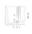
- FIG. 2D is a schematic diagram of a contacting member contacted to an inner surface of a hollow main body according to an embodiment of the invention.
- FIG. 3 is a schematic diagram of a splitting plate according to an embodiment of the invention.
- FIG. 4 is a schematic diagram of a container energy storage system connected to an electronic device according to an embodiment of the invention.
- FIG. 1A is a schematic diagram of a container energy storage system according to an embodiment of the invention
- FIG. 1B is an exploded-view diagram of the container energy storage system
- FIG. 1C is a schematic diagram of functional assemblies, a splitting plate, and a busbar.
- a container energy storage system primarily comprises a container 100 , a plurality of functional assemblies 200 , a splitting plate 300 , and a busbar 400 .
- the container 100 comprises a hollow main body 110 and two doors 120 .
- the hollow main body 110 has a hollow cuboid structure, and an accommodating space 111 is formed therein.
- An opening 112 communicating with the accommodating space 111 is formed on an end of the hollow main body 110 .
- the functional assemblies 200 , the splitting plate 300 , and the busbar 400 are disposed in the accommodating space 111 , and the splitting plate 300 is disposed between the opening 112 and the functional assemblies 200 .
- the busbar 400 connects the functional assemblies 200 with the splitting plate 300 , such that the power and the signal can be transmitted therebetween.
- Two doors 120 are pivotally connected to the hollow main body 110 , such that the doors 120 can rotate relative to the hollow main body 110 . When the doors 120 are in an open position relative to the hollow main body 110 , the user can enter the accommodating space 111 through the opening 112 to operate, replace or maintain the functional assemblies 200 and the splitting plate 300 . When the doors 120 are in the closed position relative to the hollow main body 110 , the doors 120 can cover the opening 112 .
- the container 100 is an equivalent unit, such as a twenty-foot equivalent unit (TEU) or a forty-foot equivalent unit (FEU).
- the walls of the hollow main body 110 are made of a water-resistant material and have no hole formed by secondary processing.
- the waterproof tape (not shown) is further disposed in the connecting portion between the walls. Therefore, when the doors 120 are in the closed position, the container 100 can prevent water or foreign matter from entering the accommodating space 111 , and breakage of the splitting plate 300 or the functional assemblies 200 can be avoided.
- each of the functional assemblies 200 comprises a first rack 210 , a second rack 220 , a base 230 , at least one connecting member 240 , and at least one fixing mechanism 250 .
- the first rack 210 and the second rack 220 are detachably disposed on the base 230 , and situated at opposite sides of the base 230 .
- a gap 260 can be formed between the first rack 210 and the second rack 220 .
- the appearance of the functional assemblies 200 are substantially the same, and the functional assemblies 200 are parallel and aligned with each other when the functional assemblies 200 are disposed in the accommodating space 111 of the hollow main body 110 .
- the gaps 260 of the functional assemblies 200 can be substantially aligned with each other and form a passage P. After the user enters the accommodating space 111 of the container 100 , he can pass through the passage P and access the functional assembly 200 when it needs to be maintained or replaced.
- the connecting member 240 connects the first rack 210 and the second rack 220 for preventing the first rack 210 and second rack 220 from sloping toward the gap 260 .
- the busbar 400 can be fixed on the connecting member 240 .
- the busbar 400 can be directly attached on the inner surface of the hollow main body 110 .
- the functional assembly 200 may comprise an energy storage member, a power converter, a fire box, a switchboard, a transformer, or a system controller.
- a plurality of electronic elements can be disposed on the first and second racks 210 , 220 corresponding to the different types of functional assembly 200 .
- the electronic elements can be the batteries or the power generators disposed on the first and second racks 210 , 220 .
- the electronic elements can be the smoke detectors or extinguishing units disposed on the first and second racks 210 , 220 .
- the first rack 210 and the second rack 220 of each of the functional assemblies 200 may each have an electronic connector C.
- the electronic connector C is electrically connected to the electronic elements in the functional assemblies 200 , and connected to the adjacent electronic connector C by a wire W. Therefore, the power and the signal can be rapidly transmitted between the functional assemblies 200 .
- the fixing mechanism 250 of the functional assembly 200 comprises a first nut 251 , a second nut 252 , a pole 253 , and a contacting member 254 , wherein the screw thread is formed on the pole 253 .
- the pole 253 can pass through the first nut 251 , the side wall 201 of the functional assembly 200 , and the second nut 252 , and can be fixed on the functional assembly 200 by the first nut 251 and the second nut 252 .
- the side wall 201 is situated between the first nut 251 and the second nut 252 .
- the contacting member 254 has a disc structure, and connects an end of the pole 253 .
- the contacting member 254 of the fixing mechanism 250 can contact the inner surface of the hollow main body 110 ( FIG. 2D ).
- fixing mechanisms 250 are formed on the left side, right side, and top of the functional assembly 200 ( FIG. 2A ). Therefore, the functional assemblies 200 can be fixed in the accommodating space 110 by friction without breaking any walls of the container 100 .
- the contacting member 254 has a disc structure, the contacting area between the contacting member 254 and the hollow main body 110 can be increased.
- the functional assemblies 200 can be fixed steadily in the hollow main body 110 .
- the normal container 100 has a wall with a corrugated structure.
- the distance between the contacting member 254 and the side wall 201 of the functional assembly 200 is adjustable.
- the contacting member 254 can contact the inner surface of the hollow main body 110 .
- fixing mechanisms 250 merely disposed on the left side and right side of the functional assembly 200 (the fixing mechanism 250 on the top can be omitted). In some embodiments, the fixing mechanism 250 is merely disposed on the top of the functional assembly 200 (the fixing mechanisms 250 on the left side and right side can be omitted). In some embodiments, the fixing mechanism 250 is merely disposed on the left side or the right side of the functional assembly 200 (the fixing mechanisms 250 on the other side and top can be omitted), and the other side of the functional assembly 200 can be attached on the inner surface of the hollow main body 110 .
- the splitting plate 300 electrically connected to the functional assemblies 200 comprises a board 310 and a hatch 320 , wherein an entrance 315 is formed on the board 310 and corresponds to the passage P formed by the functional assemblies 200 .
- the hatch 320 is pivotally connected to the board 310 for closing the entrance 315 .
- the dimensions of the cross section of the hollow main body 110 is substantially the same as the dimensions of the splitting plate 300 .
- the splitting plate 300 comprises a water-resistant material, and the waterproof tape (not shown) is filled between the inner surface of the hollow main body 100 and the splitting plate 300 .
- the container energy storage system of the invention can still protect the functional assemblies 200 therein from the ingress of water and foreign matter.
- the splitting plate 300 is substantially parallel to the functional assemblies 200 .
- the splitting plate 300 is substantially parallel to the doors 120 .
- the board 310 has at least one connecting port 311 , at least one input unit 312 , a display unit 313 , and a lock unit 314 .
- the connecting port 311 is used to connect the external electronic device E for providing the power thereto (as shown in FIG. 4 ).
- the input unit 312 is used to input the control signal, so that the user can change the parameters of the functional assemblies 200 without entering the passage P.
- the display unit 313 displays the data and condition of the functional assemblies 200 .
- the lock unit 314 controls the hatch 320 to open or to close.
- the display unit 313 can perform the functions of an input unit 312 , such as a touch screen.
- a container energy storage system is provided.
- the splitting plate is electrically connected to the functional assemblies and disposed between the opening and the functional assemblies, and the container energy storage system can provide power via the functional assemblies without breaking the walls of the container. Therefore, when the doors of the container are in the closed position, water and foreign matter cannot enter the interior of the container through the wall of the container.
Priority Applications (1)
| Application Number | Priority Date | Filing Date | Title |
|---|---|---|---|
| US15/945,213 US10439372B2 (en) | 2016-02-24 | 2018-04-04 | Container energy storage system |
Applications Claiming Priority (3)
| Application Number | Priority Date | Filing Date | Title |
|---|---|---|---|
| TW105105381A TWI619426B (zh) | 2016-02-24 | 2016-02-24 | 貨櫃式儲能系統 |
| TW105105381 | 2016-02-24 | ||
| TW105105381A | 2016-02-24 |
Related Child Applications (1)
| Application Number | Title | Priority Date | Filing Date |
|---|---|---|---|
| US15/945,213 Continuation US10439372B2 (en) | 2016-02-24 | 2018-04-04 | Container energy storage system |
Publications (2)
| Publication Number | Publication Date |
|---|---|
| US20170244225A1 US20170244225A1 (en) | 2017-08-24 |
| US9966739B2 true US9966739B2 (en) | 2018-05-08 |
Family
ID=59629542
Family Applications (2)
| Application Number | Title | Priority Date | Filing Date |
|---|---|---|---|
| US15/298,655 Active 2036-11-08 US9966739B2 (en) | 2016-02-24 | 2016-10-20 | Container energy storage system |
| US15/945,213 Active US10439372B2 (en) | 2016-02-24 | 2018-04-04 | Container energy storage system |
Family Applications After (1)
| Application Number | Title | Priority Date | Filing Date |
|---|---|---|---|
| US15/945,213 Active US10439372B2 (en) | 2016-02-24 | 2018-04-04 | Container energy storage system |
Country Status (3)
| Country | Link |
|---|---|
| US (2) | US9966739B2 (zh) |
| JP (2) | JP6367901B2 (zh) |
| TW (1) | TWI619426B (zh) |
Cited By (4)
| Publication number | Priority date | Publication date | Assignee | Title |
|---|---|---|---|---|
| US20180066485A1 (en) * | 2015-03-24 | 2018-03-08 | Fmc Kongsberg Subsea As | Modular system and method for controlling subsea operations |
| US10439372B2 (en) * | 2016-02-24 | 2019-10-08 | Delta Electronics | Container energy storage system |
| US11034511B2 (en) | 2019-04-01 | 2021-06-15 | Irish Dawg Industries, LLC | Module integrated cargo securement system |
| US11167915B1 (en) | 2021-03-26 | 2021-11-09 | Irish Dawg Industries, LLC | Multipurpose relocatable structure and lifting systems and methods |
Families Citing this family (9)
| Publication number | Priority date | Publication date | Assignee | Title |
|---|---|---|---|---|
| KR20190048081A (ko) * | 2017-10-30 | 2019-05-09 | 엘에스산전 주식회사 | 일체형 전력변환 및 계통연계 시스템 |
| DE102018114183A1 (de) | 2018-06-13 | 2019-12-19 | Hofer Mechatronik Gmbh | Testeinrichtung für elektrochemische Konverter sowie Betriebsverfahren hierfür |
| DE102019201408B3 (de) * | 2019-02-04 | 2020-07-30 | Atlas Elektronik Gmbh | Elektronikmodul |
| DE102019102639A1 (de) | 2019-02-04 | 2020-08-06 | Sma Solar Technology Ag | Behälter für eine Energieversorgungsanlage, Energieversorgungsanlage und Verfahren zu deren Bereitstellung |
| CN112615273B (zh) * | 2020-12-25 | 2022-04-22 | 广东艾尔凯电力科技有限公司 | 一种基于物联网的节能散热型高低压成套配电柜 |
| KR20220117355A (ko) | 2021-02-15 | 2022-08-24 | 주식회사 엘지에너지솔루션 | 이중문을 포함하는 에너지 저장장치 |
| US20230138106A1 (en) * | 2021-10-28 | 2023-05-04 | Caterpillar Inc. | Containerized battery system and anti-condensation control system for same |
| CN115207803B (zh) * | 2022-06-23 | 2023-09-19 | 江苏富士特电气技术有限公司 | 一种集电子设备于一体的多功能储能系统 |
| CN115207438B (zh) * | 2022-09-09 | 2022-12-20 | 佛山市天劲新能源科技有限公司 | 一种电池组底板组装装置 |
Citations (22)
| Publication number | Priority date | Publication date | Assignee | Title |
|---|---|---|---|---|
| US3963290A (en) * | 1975-03-20 | 1976-06-15 | Johann Birkart, Internationale Spedition | Hanging fitting for freight receptacles, known as containers |
| US4639005A (en) * | 1985-06-03 | 1987-01-27 | Birkley Adrian N | Carriage apparatus for saw tables |
| US4951823A (en) * | 1989-11-16 | 1990-08-28 | Container Corporation Of America | Paperboard load block |
| US20090007823A1 (en) * | 2007-07-06 | 2009-01-08 | Ben Yu | Work table with leveling screws |
| US20090229194A1 (en) * | 2008-03-11 | 2009-09-17 | Advanced Shielding Technologies Europe S.I. | Portable modular data center |
| US20100091449A1 (en) * | 2006-06-01 | 2010-04-15 | Jimmy Clidaras | Modular Computing Environments |
| US8047904B2 (en) * | 2006-09-13 | 2011-11-01 | Oracle America, Inc. | Cooling method for a data center in a shipping container |
| TW201144997A (en) | 2009-12-17 | 2011-12-16 | Delta Electronics Inc | Air conditioning system of portable data center |
| JP2012053747A (ja) | 2010-09-02 | 2012-03-15 | Ntt Facilities Inc | コンテナ型データセンター |
| JP2012072999A (ja) | 2010-09-29 | 2012-04-12 | Nsk Corp | 情報処理関連機器用空調システム |
| US20130032310A1 (en) * | 2011-08-02 | 2013-02-07 | Power Distribution Inc. | Transportable, environmentally-controlled equipment enclosure |
| TW201318935A (zh) | 2011-08-15 | 2013-05-16 | George E Kochanowski | 可逆式可折合貨櫃 |
| JP2013131416A (ja) | 2011-12-22 | 2013-07-04 | Sekisui Chem Co Ltd | 蓄電池の設置構造 |
| WO2013111426A1 (ja) | 2012-01-24 | 2013-08-01 | 日本碍子株式会社 | 電力貯蔵装置及び電力貯蔵装置の運転方法 |
| US8613364B2 (en) * | 2009-10-26 | 2013-12-24 | Dell Products, Lp | Modular datacenter server rack retention |
| US20140185209A1 (en) * | 2012-12-28 | 2014-07-03 | Hon Hai Precision Industry Co., Ltd. | Container data center with server cabinet assembly |
| US8947879B2 (en) * | 2010-12-16 | 2015-02-03 | Smartcube, Llc | Portable computer server enclosure |
| GB2518843A (en) * | 2013-10-01 | 2015-04-08 | Cannon Technologies Ltd | Shock attenuation system |
| US9038838B2 (en) * | 2013-01-07 | 2015-05-26 | Eirik Smedsrud Skeid | Intermodal container |
| US9101210B2 (en) * | 2010-11-30 | 2015-08-11 | Wistron Corporation | Track type supporting mechanism and supporting system |
| US20170210555A1 (en) * | 2014-07-24 | 2017-07-27 | Deutsche Post Ag | Air freight container and/or air freight pallet |
| US9828172B2 (en) * | 2013-01-07 | 2017-11-28 | Eirik Skeid | Intermodal container |
Family Cites Families (16)
| Publication number | Priority date | Publication date | Assignee | Title |
|---|---|---|---|---|
| JP2986293B2 (ja) * | 1992-08-31 | 1999-12-06 | 株式会社日立製作所 | 可搬形交換設備および収容箱 |
| EP0959011B1 (en) * | 1998-05-20 | 2009-05-13 | Coca-Cola Enterprises Inc. | Shipping pallet |
| JP3104190U (ja) | 2004-03-24 | 2004-09-02 | 株式会社エヌ・ティ・ティ・ドコモ北陸 | 無線機器収容局舎 |
| JP3104189U (ja) * | 2004-03-24 | 2004-09-02 | 株式会社エヌ・ティ・ティ・ドコモ北陸 | 無線機器収容局舎 |
| RU2011118460A (ru) * | 2008-10-07 | 2012-11-20 | Премиум Пауэр Корпорейшн (Us) | Система и способ для транспортировки энергии |
| JP5546122B2 (ja) * | 2008-12-08 | 2014-07-09 | ジャパンマリンユナイテッド株式会社 | 蓄電池パッケージ |
| US7944692B2 (en) * | 2009-06-12 | 2011-05-17 | American Power Conversion Corporation | Method and apparatus for installation and removal of overhead cooling equipment |
| FR2973579B1 (fr) * | 2011-04-01 | 2014-04-18 | Accumulateurs Fixes | Implantation de baies batteries en conteneur |
| KR101255243B1 (ko) * | 2011-04-15 | 2013-04-16 | 삼성에스디아이 주식회사 | 랙 하우징 조립체 및 이를 구비한 전력저장장치 |
| KR101473385B1 (ko) * | 2011-05-31 | 2014-12-16 | 주식회사 엘지화학 | 전력 저장 장치, 이를 이용한 전력 저장 시스템 및 전력 저장 시스템의 구성 방법 |
| JP5927702B2 (ja) * | 2012-09-12 | 2016-06-01 | 株式会社日立製作所 | 電池パック及びそれを備えたコンテナ |
| EP2940754A1 (en) * | 2012-12-28 | 2015-11-04 | Hitachi, Ltd. | Power storage apparatus |
| JP5762645B2 (ja) * | 2013-04-24 | 2015-08-12 | 株式会社日立システムズ | コンテナ型データセンター |
| WO2015186343A1 (ja) | 2014-06-06 | 2015-12-10 | パナソニックIpマネジメント株式会社 | 電池室 |
| TWI619426B (zh) * | 2016-02-24 | 2018-03-21 | 台達電子工業股份有限公司 | 貨櫃式儲能系統 |
| GB2564411A (en) * | 2017-07-06 | 2019-01-16 | Htl Group Ltd | Containerised system with modules |
-
2016
- 2016-02-24 TW TW105105381A patent/TWI619426B/zh active
- 2016-10-20 US US15/298,655 patent/US9966739B2/en active Active
- 2016-12-15 JP JP2016243469A patent/JP6367901B2/ja active Active
-
2018
- 2018-04-04 US US15/945,213 patent/US10439372B2/en active Active
- 2018-07-05 JP JP2018127933A patent/JP6622357B2/ja active Active
Patent Citations (26)
| Publication number | Priority date | Publication date | Assignee | Title |
|---|---|---|---|---|
| US3963290A (en) * | 1975-03-20 | 1976-06-15 | Johann Birkart, Internationale Spedition | Hanging fitting for freight receptacles, known as containers |
| US4639005A (en) * | 1985-06-03 | 1987-01-27 | Birkley Adrian N | Carriage apparatus for saw tables |
| US4951823A (en) * | 1989-11-16 | 1990-08-28 | Container Corporation Of America | Paperboard load block |
| US8218322B2 (en) * | 2006-06-01 | 2012-07-10 | Google Inc. | Modular computing environments |
| US8743543B2 (en) * | 2006-06-01 | 2014-06-03 | Google Inc. | Modular computing environments |
| US20100091449A1 (en) * | 2006-06-01 | 2010-04-15 | Jimmy Clidaras | Modular Computing Environments |
| US7738251B2 (en) * | 2006-06-01 | 2010-06-15 | Google Inc. | Modular computing environments |
| US8047904B2 (en) * | 2006-09-13 | 2011-11-01 | Oracle America, Inc. | Cooling method for a data center in a shipping container |
| US20090007823A1 (en) * | 2007-07-06 | 2009-01-08 | Ben Yu | Work table with leveling screws |
| US20090229194A1 (en) * | 2008-03-11 | 2009-09-17 | Advanced Shielding Technologies Europe S.I. | Portable modular data center |
| US9144176B2 (en) * | 2009-10-26 | 2015-09-22 | Dell Products, Lp | Modular datacenter server rack retention |
| US8613364B2 (en) * | 2009-10-26 | 2013-12-24 | Dell Products, Lp | Modular datacenter server rack retention |
| TW201144997A (en) | 2009-12-17 | 2011-12-16 | Delta Electronics Inc | Air conditioning system of portable data center |
| JP2012053747A (ja) | 2010-09-02 | 2012-03-15 | Ntt Facilities Inc | コンテナ型データセンター |
| JP2012072999A (ja) | 2010-09-29 | 2012-04-12 | Nsk Corp | 情報処理関連機器用空調システム |
| US9101210B2 (en) * | 2010-11-30 | 2015-08-11 | Wistron Corporation | Track type supporting mechanism and supporting system |
| US8947879B2 (en) * | 2010-12-16 | 2015-02-03 | Smartcube, Llc | Portable computer server enclosure |
| US20130032310A1 (en) * | 2011-08-02 | 2013-02-07 | Power Distribution Inc. | Transportable, environmentally-controlled equipment enclosure |
| TW201318935A (zh) | 2011-08-15 | 2013-05-16 | George E Kochanowski | 可逆式可折合貨櫃 |
| JP2013131416A (ja) | 2011-12-22 | 2013-07-04 | Sekisui Chem Co Ltd | 蓄電池の設置構造 |
| WO2013111426A1 (ja) | 2012-01-24 | 2013-08-01 | 日本碍子株式会社 | 電力貯蔵装置及び電力貯蔵装置の運転方法 |
| US20140185209A1 (en) * | 2012-12-28 | 2014-07-03 | Hon Hai Precision Industry Co., Ltd. | Container data center with server cabinet assembly |
| US9038838B2 (en) * | 2013-01-07 | 2015-05-26 | Eirik Smedsrud Skeid | Intermodal container |
| US9828172B2 (en) * | 2013-01-07 | 2017-11-28 | Eirik Skeid | Intermodal container |
| GB2518843A (en) * | 2013-10-01 | 2015-04-08 | Cannon Technologies Ltd | Shock attenuation system |
| US20170210555A1 (en) * | 2014-07-24 | 2017-07-27 | Deutsche Post Ag | Air freight container and/or air freight pallet |
Cited By (7)
| Publication number | Priority date | Publication date | Assignee | Title |
|---|---|---|---|---|
| US20180066485A1 (en) * | 2015-03-24 | 2018-03-08 | Fmc Kongsberg Subsea As | Modular system and method for controlling subsea operations |
| US10570682B2 (en) * | 2015-03-24 | 2020-02-25 | Fmc Kongsberg Subsea As | Modular system and method for controlling subsea operations |
| US10439372B2 (en) * | 2016-02-24 | 2019-10-08 | Delta Electronics | Container energy storage system |
| US11034511B2 (en) | 2019-04-01 | 2021-06-15 | Irish Dawg Industries, LLC | Module integrated cargo securement system |
| US11767162B2 (en) | 2019-04-01 | 2023-09-26 | Irish Dawg Industries, LLC | Modular facility formation system and shipping method |
| US11167915B1 (en) | 2021-03-26 | 2021-11-09 | Irish Dawg Industries, LLC | Multipurpose relocatable structure and lifting systems and methods |
| US11655098B2 (en) | 2021-03-26 | 2023-05-23 | Irish Dawg Industries, LLC | Multipurpose relocatable structure and lifting systems and methods |
Also Published As
| Publication number | Publication date |
|---|---|
| JP2019009128A (ja) | 2019-01-17 |
| US10439372B2 (en) | 2019-10-08 |
| US20170244225A1 (en) | 2017-08-24 |
| JP6622357B2 (ja) | 2019-12-18 |
| TW201731368A (zh) | 2017-09-01 |
| JP2017153341A (ja) | 2017-08-31 |
| TWI619426B (zh) | 2018-03-21 |
| JP6367901B2 (ja) | 2018-08-01 |
| US20180226774A1 (en) | 2018-08-09 |
Similar Documents
| Publication | Publication Date | Title |
|---|---|---|
| US10439372B2 (en) | Container energy storage system | |
| WO2015025489A1 (ja) | ケーブルダクト内蔵型電気機器 | |
| WO2017206594A1 (zh) | 一种电路板拼板、电路板和移动终端 | |
| US10297933B2 (en) | Wire plug-in aid sleeve structure for wire connection terminal | |
| WO2014073224A1 (ja) | 電気的接続部材、携帯電子機器、及び電気コネクタ | |
| US20170325353A1 (en) | Rack sidecar for additional it equipment and cable management | |
| EP1854288B1 (en) | Display base with forward facing interconnect panel | |
| US10290981B2 (en) | Power outlet device | |
| US20150022969A1 (en) | Computer case with recorded open and closed states | |
| US20140218844A1 (en) | Rack for Electronic Devices | |
| WO2014073225A1 (ja) | コネクタ接続構造、画像処理装置、携帯電子機器、及び電気コネクタ | |
| CN110489296B (zh) | 一种自动化测试平台 | |
| CN202363307U (zh) | 一种墙壁开关 | |
| CN101630432B (zh) | 光触发的动封检测机构以及具有光触发的电子封 | |
| EP2840669B1 (en) | Connector and electronic device including the same | |
| CN219286907U (zh) | 一种电气设备工作环境信息监测装置 | |
| CN207884135U (zh) | 一种插座式配电箱 | |
| JP5780360B2 (ja) | コンテナ及びコンテナ型情報処理装置 | |
| CN209402035U (zh) | 一种带温度检测和报警功能的配电箱 | |
| US6426458B1 (en) | Control cabinet for a tablet press | |
| ITMI981279A1 (it) | Dispositivo serracavi e di drenaggio verso massa delle correnti parassite indotte su cavi schermati all'attraversamento di una | |
| JP2021071828A (ja) | ガス警報器 | |
| CN207473009U (zh) | 测试柜及自动化测试系统 | |
| CN208062566U (zh) | 一种防盗配电箱装置 | |
| JP2017005173A (ja) | 電気機器収納用ラック |
Legal Events
| Date | Code | Title | Description |
|---|---|---|---|
| AS | Assignment |
Owner name: DELTA ELECTRONICS, INC., TAIWAN Free format text: ASSIGNMENT OF ASSIGNORS INTEREST;ASSIGNORS:CHEN, CHIN-MING;LIN, MU-MIN;REEL/FRAME:040266/0875 Effective date: 20160415 |
|
| STCF | Information on status: patent grant |
Free format text: PATENTED CASE |
|
| MAFP | Maintenance fee payment |
Free format text: PAYMENT OF MAINTENANCE FEE, 4TH YEAR, LARGE ENTITY (ORIGINAL EVENT CODE: M1551); ENTITY STATUS OF PATENT OWNER: LARGE ENTITY Year of fee payment: 4 |