US9921525B2 - Image forming apparatus - Google Patents
Image forming apparatus Download PDFInfo
- Publication number
- US9921525B2 US9921525B2 US15/163,136 US201615163136A US9921525B2 US 9921525 B2 US9921525 B2 US 9921525B2 US 201615163136 A US201615163136 A US 201615163136A US 9921525 B2 US9921525 B2 US 9921525B2
- Authority
- US
- United States
- Prior art keywords
- forming apparatus
- image forming
- transfer
- damping
- rubbing
- Prior art date
- Legal status (The legal status is an assumption and is not a legal conclusion. Google has not performed a legal analysis and makes no representation as to the accuracy of the status listed.)
- Active
Links
Images


Classifications
-
- G—PHYSICS
- G03—PHOTOGRAPHY; CINEMATOGRAPHY; ANALOGOUS TECHNIQUES USING WAVES OTHER THAN OPTICAL WAVES; ELECTROGRAPHY; HOLOGRAPHY
- G03G—ELECTROGRAPHY; ELECTROPHOTOGRAPHY; MAGNETOGRAPHY
- G03G15/00—Apparatus for electrographic processes using a charge pattern
- G03G15/14—Apparatus for electrographic processes using a charge pattern for transferring a pattern to a second base
- G03G15/16—Apparatus for electrographic processes using a charge pattern for transferring a pattern to a second base of a toner pattern, e.g. a powder pattern, e.g. magnetic transfer
- G03G15/1605—Apparatus for electrographic processes using a charge pattern for transferring a pattern to a second base of a toner pattern, e.g. a powder pattern, e.g. magnetic transfer using at least one intermediate support
- G03G15/1615—Apparatus for electrographic processes using a charge pattern for transferring a pattern to a second base of a toner pattern, e.g. a powder pattern, e.g. magnetic transfer using at least one intermediate support relating to the driving mechanism for the intermediate support, e.g. gears, couplings, belt tensioning
Definitions
- the present invention relates to an image forming apparatus, such as a copier, a printer, a facsimile, or a multifunction machine, configured to form an image on a sheet.
- an image forming apparatus such as a copier, a printer, a facsimile, or a multifunction machine, configured to form an image on a sheet.
- Some related-art electrophotographic image forming apparatuses such as a copier or a printer, employ intermediate transfer belts as transfer belts.
- a full-color image is formed through a primary-transfer step and a secondary-transfer step.
- a toner image formed on a surface of an electrophotographic photoconductive member is primarily transferred to the intermediate transfer belt.
- the primary-transfer step is performed for forming each of a plurality of toner images in different colors, whereby a combination of toner images in different colors is formed on the intermediate transfer belt.
- the combination of toner images in different colors is transferred to a surface of a transfer material such as a piece of paper. The combination of toner images thus transferred to the transfer material is then fixed by a fixing device. Thus, a full-color image is obtained.
- a transfer device included in such an image forming apparatus includes a transfer member in the form of a roller, a blade, a brush, or the like.
- the transfer member is a contact member that is provided in contact with the inner peripheral surface of the intermediate transfer belt at a position across from the photoconductive member.
- Japanese Patent Laid-Open No. 2011-248385 an image forming apparatus including a brush-type transfer member as a transfer device is disclosed.
- the brush-type transfer member according to Japanese Patent Laid-Open No. 2011-248385 includes a stainless-steel metal holder (a supporting member) that supports a brush thereon with the aid of two-sided adhesive tape.
- the brush include a plurality of conductive fibers. That is, the transfer member according to Japanese Patent Laid-Open No. 2011-248385 is disclosed as a brush-type rubbing member that is unrotatably in contact with the intermediate transfer belt and thus rubs the intermediate transfer belt.
- the present invention provides a simple mechanism that damps the vibration of a supporting member due to a frictional force generated between a rubbing member and a rubbed member.
- an image forming apparatus including an image bearing member configured to bear a toner image, a rotatable transfer belt to which the toner image on the image bearing member is transferred to a transfer material, and a transfer device provided in contact with the transfer belt and configured to transfer the toner image from the image bearing member to the transfer belt.
- the transfer device includes a rubbing member provided in contact with the transfer belt, a supporting member supporting the rubbing member, and a damping member configured to damp vibration of the transfer device.
- the damping member is fastened to the supporting member, and an end of the damping member in a width direction that is orthogonal to a direction of rotation of the transfer belt is a free end.
- FIG. 1 is a schematic sectional view of an image forming apparatus according to a first embodiment of the present invention.
- FIG. 2 is a schematic sectional view of an intermediate transfer unit according to the first embodiment.
- FIG. 3 is a schematic perspective view of the intermediate transfer unit.
- FIG. 4 is a schematic top view of a primary-transfer unit according to the first embodiment.
- FIG. 5 is a schematic diagram illustrating the relationship between the primary-transfer unit and a photoconductive drum according to the first embodiment.
- FIG. 6A is a diagram illustrating dimensions of a transfer member in a belt-width direction according to the first embodiment.
- FIG. 6B is a schematic perspective view of the transfer member.
- FIG. 7 is a perspective view of one end of the primary-transfer unit according to the first embodiment.
- FIG. 8 is a sectional view of the one end of the primary-transfer unit according to the first embodiment.
- FIG. 9 is a schematic sectional view of the primary-transfer unit that is seen in the axial direction thereof according to the first embodiment.
- FIG. 10 is a perspective view of the primary-transfer unit that is seen from the downstream side in a direction of belt rotation according to the first embodiment.
- FIG. 11A is a side view of a damping member according to the first embodiment and illustrates dimensions thereof.
- FIG. 11B is a diagram illustrating the angle of the damping member.
- FIG. 12 is another schematic top view of the primary-transfer unit according to the first embodiment.
- FIG. 13A is a perspective view of a primary-transfer unit according to a first comparative example.
- FIG. 13B is a perspective view of a primary-transfer unit according to a second comparative example.
- FIG. 14 is a graph given for comparison of acceleration among the first embodiment, the first comparative example, and the second comparative example.
- FIG. 15 is a schematic diagram of a primary-transfer unit according to a first modification of the first embodiment.
- FIG. 16 is a schematic diagram of a primary-transfer unit according to a second modification of the first embodiment.
- FIGS. 17A and 17B are schematic diagrams of primary-transfer units according to third and fourth modifications, respectively, of the first embodiment.
- FIGS. 18A and 18B are schematic diagrams of a primary-transfer unit according to a fifth modification of the first embodiment.
- FIGS. 19A and 19B are schematic diagrams of a charging unit according to a second embodiment of the present invention.
- FIG. 20 is a schematic diagram of a primary-transfer unit according to a sixth modification of the first embodiment.
- FIG. 21 is a schematic diagram of a sheet feeding mechanism according to a third embodiment of the present invention.
- FIG. 22 is a sectional view of the sheet feeding mechanism.
- FIG. 23 is a perspective view of the sheet feeding mechanism.
- FIG. 1 is a schematic sectional view of an image forming apparatus 1 according to a first embodiment of the present invention.
- the image forming apparatus 1 according to the first embodiment is an electrophotographic full-color laser-beam printer.
- the image forming apparatus 1 electrophotographically forms an image on a transfer material, such as a recording sheet or an overhead-projector (OHP) sheet, in accordance with a signal transmitted to the image forming apparatus 1 from an external apparatus, such as a personal computer, communicably connected to the image forming apparatus 1 .
- a transfer material such as a recording sheet or an overhead-projector (OHP) sheet
- surfaces of photoconductive drums (image bearing members) 103 y, 103 m , 103 c, and 103 k are charged by charging rollers 105 y, 105 m , 105 c, and 105 k, respectively.
- the charged surfaces of the photoconductive drums 103 y, 103 m, 103 c, and 103 k are exposed to light emitted from a laser scanner 104 , serving as an exposure device, in accordance with image information, whereby electrostatic latent images are formed on the respective photoconductive drums 103 y, 103 m, 103 c, and 103 k .
- the electrostatic latent images are developed with yellow, magenta, cyan, and black toners by developing members 112 y , 112 m, 112 c, and 112 k, respectively, whereby toner images in the respective colors are formed.
- the toner images thus formed on the respective photoconductive drums 103 y, 103 m , 103 c, and 103 k are primarily transferred to an intermediate transfer belt 106 , which is in the form of an endless transfer belt, in such a manner as to be superposed one on top of another.
- one of transfer materials S stacked in a cassette 10 is conveyed by a feed roller 12 , a conveying roller 13 , a separating roller 14 , and a pair of registration rollers 100 to a nip (secondary-transfer part) defined between a secondary-transfer counter roller 101 and a secondary-transfer roller 102 .
- the transfer material S thus conveyed to the secondary-transfer part undergoes the secondary transfer, in which the toner images superposed on the intermediate transfer belt 106 are secondarily transferred to the transfer material S.
- the transfer material S now having the toner images is heated and pressed by a fixing device (including a fixing film 200 and a pressing roller 201 ), whereby the toner images on the transfer material S are fixed.
- the transfer material S now having the fixed toner images is discharged onto a discharge tray 204 by a discharge roller 202 and a discharge follower roller 203 .
- Residual toner particles on the surface of the intermediate transfer belt 106 that has undergone the secondary transfer are charged by a residual-toner-charging unit 120 .
- the residual toner particles are charged by the residual-toner-charging unit 120 to a polarity opposite to the normal polarity and are then moved from the intermediate transfer belt 106 to the photoconductive drums 103 y, 103 m, 103 c, and 103 k at respective primary-transfer parts.
- the above steps of charging, exposure, development, and primary transfer are performed in first to fourth stations Sa, Sb, Sc, and Sd in that order from the upstream side in a direction of rotation of the intermediate transfer belt 106 .
- a full-color image that is composed of toner images having the four colors of yellow, magenta, cyan, and black and superposed one on top of another on the intermediate transfer belt 106 is formed on the transfer material S.
- the steps of charging, exposure, development, and primary transfer are performed in any one of the first to fourth stations Sa, Sb, Sc, and Sd.
- FIG. 2 is a schematic sectional view of the intermediate transfer unit 130 .
- FIG. 3 is a schematic perspective view of the intermediate transfer unit 130 .
- the intermediate transfer unit 130 according to the first embodiment illustrated in FIGS. 2 and 3 is attachable to and detachable from the body of the image forming apparatus 1 .
- the intermediate transfer belt 106 having an endless shape and being rotatable is stretched around three stretching rollers: namely, the secondary-transfer counter roller 101 , a tension roller 110 , and an assist roller 111 .
- the secondary-transfer counter roller 101 , the tension roller 110 , and the assist roller 111 are each rotatably supported by a left side plate 108 and a right side plate 109 .
- the primary-transfer units 112 y, 112 m, 112 c, and 112 k are supported by a unit frame 107 at respective positions facing the respective photoconductive drums 103 y, 103 m, 103 c, and 103 k.
- the tension roller 110 urges the intermediate transfer belt 106 from the inner side of the intermediate transfer belt 106 with a tension spring (not illustrated) and thus defines, with the aid of the assist roller 111 , a belt surface along which the transfer material S is guided to the secondary-transfer part.
- the primary-transfer units 112 y, 112 m, 112 c, and 112 k are provided for the respective colors and all have the same configuration. Therefore, the suffixes y, m, c, and k in the reference numerals given to associated elements are omitted in the following description.
- the primary-transfer units 112 are each a transfer device that transfers a toner image from a corresponding one of the photoconductive drums 103 to the intermediate transfer belt 106 (the transfer belt).
- FIG. 4 is a schematic top view of the primary-transfer unit 112 .
- FIG. 5 is a schematic diagram illustrating the relationship between the primary-transfer unit 112 and the photoconductive drum 103 .
- the primary-transfer unit 112 includes a transfer member 113 that is in contact with the inner peripheral surface of the intermediate transfer belt 106 , and a supporting member 114 that supports the transfer member 113 .
- the transfer member 113 is fixed to the supporting member 114 in such a manner as to be unrotatable with respect to the intermediate transfer belt 106 , which is rotatable.
- the transfer member 113 in such a state is in contact with the intermediate transfer belt 106 . Therefore, the transfer member 113 rubs the intermediate transfer belt 106 .
- the primary-transfer unit 112 further includes positioning portions 115 , pressing members 116 as compression springs, a contact member 117 as a power feeding unit, and a damping member 118 .
- the positioning portions 115 determine the position of the transfer member 113 with respect to the photoconductive drum 103 in the direction of rotation of the intermediate transfer belt 106 .
- the transfer member 113 is pressed toward the photoconductive drum 103 by the pressing members 116 .
- the photoconductive drum 103 and the intermediate transfer belt 106 are closely in contact with each other, and the intermediate transfer belt 106 and the transfer member 113 are closely in contact with each other.
- a length L of the transfer member 113 in the long-side direction thereof (a widthwise direction of the intermediate transfer belt 106 that is orthogonal to the direction of rotation of the intermediate transfer belt 106 ) is 238 mm.
- a width W of the transfer member 113 in the short-side direction thereof (corresponding to the direction of rotation of the intermediate transfer belt 106 ) is 4 mm.
- the transfer member 113 is a brush member that includes a base fabric portion (not illustrated) and a nap portion ⁇ .
- the nap portion ⁇ includes a plurality of conductive fibers (for example, conductive nylon fibers) and is fixed to the base fabric portion.
- the base fabric portion is supported by the supporting member 114 .
- the transfer member 113 is sectioned in the long-side direction thereof, i.e., in the widthwise direction of the intermediate transfer belt 106 , into the nap portion ⁇ and two welded end parts ⁇ .
- the nap portion ⁇ of the transfer member 113 has a length L1 of 216 mm, and the welded end parts ⁇ of the transfer member 113 at the two ends of the nap portion ⁇ each have a length L2 of 11 mm.
- the nap portion a has a thickness H1 of about 1.5 mm, and the welded end parts ⁇ each have a thickness H2 of about 0.5 mm.
- the nap portion ⁇ has elasticity and is in contact with the intermediate transfer belt 106 .
- the transfer member 113 may be made of any of the following materials: conductive urethane foam, an ultrahigh-molecular-weight polyethylene transfer material, and the like; and any combination of the foregoing materials.
- the transfer member 113 is fixedly attached to the top surface of the supporting member 114 with two-sided adhesive tape (not illustrated) and is thus supported by the supporting member 114 .
- the supporting member 114 is made of a steel plate having a thickness of 0.8 mm and has a rectangular U shape in cross-sectional view.
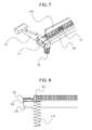
- FIG. 7 is a perspective view of one end of the primary-transfer unit 112 .
- FIG. 8 is a sectional view of the one end of the primary-transfer unit 112 .
- the contact member 117 is a leaf-spring-type member having a rectangular U shape.
- the positioning portions 115 are each connected to a corresponding one of the two ends of the supporting member 114 .
- the contact member 117 pinches the welded end part ⁇ (a part of the transfer member 113 ) and the positioning portion 115 at the one end of the primary-transfer unit 112 .
- the upper inner surface of the contact member 117 is in contact with the welded end part ⁇ of the transfer member 113 .
- the lower outer surface of the contact member 117 is in contact with the pressing member 116 at the one end of the primary-transfer unit 112 .
- the transfer member 113 is pressed by the pressing member 116 with the positioning portion 115 and the supporting member 114 interposed therebetween.
- the pressing member 116 is a conductive compression spring.
- the other end of the primary-transfer unit 112 has the same configuration, except the contact member 117 , which is provided only at the one end of the primary-transfer
- each of the pressing members 116 is electrically connected to the transfer member 113 , and a primary-transfer voltage is allowed to be applied from an electrical board (not illustrated) provided on the body of the image forming apparatus 1 to the transfer member 113 through the pressing members 116 and the contact member 117 .
- the supporting member 114 and each of the positioning portions 115 are fixed to each other by light press-fitting.
- the positioning portions 115 are made of resin and are provided at the two respective ends of the supporting member 114 in the widthwise direction of the intermediate transfer belt 106 (the direction is hereinafter referred to as “the belt-width direction”).
- FIG. 9 is a schematic sectional view of the primary-transfer unit 112 that is seen in the axial direction thereof.
- the positioning portions 115 are each in engagement with a supporting portion 107 a of the unit frame 107 , thereby being positioned in the direction of rotation of the intermediate transfer belt 106 (the direction of the arrow illustrated in FIG. 9 , the direction is hereinafter referred to as “the direction of belt rotation”).
- the positioning portion 115 is rotatable about the point of engagement.
- FIG. 10 is a perspective view of the primary-transfer unit 112 that is seen from the downstream side in the direction of belt rotation.
- the primary-transfer unit 112 includes the damping member 118 .
- the damping member 118 is supported by the supporting member 114 .
- the damping member 118 is made of a steel plate having a thickness of 1.2 mm.
- the damping member 118 is fastened to a central part, in the belt-width direction, of a side face of the supporting member 114 with a screw 180 , thereby being connected to the supporting member 114 .
- the damping member 118 is fastened to the above position.
- FIG. 11A is a side view of the damping member 118 and illustrates the dimensions thereof.
- FIG. 11B is a diagram illustrating the angle of the damping member 118 .
- the damping member 118 has a length l of 210 mm in the belt-width direction and has a hole for connection to the supporting member 114 at the center thereof in thebelt-width direction.
- the damping member 118 has a length w of 9 mm in the direction of belt rotation.
- the two ends of the damping member 118 in the belt-width direction are free ends and are each shifted by an angle D of 3° with respect to the belt-width-direction center of the damping member 118 .
- the damping member 118 has a curved shape that is bent at the belt-width-direction center thereof by a predetermined angle. Hence, the damping member 118 is out of contact with any members including the supporting member 114 , except at the center thereof.
- FIG. 12 is a schematic top view of the primary-transfer unit 112 illustrated for explaining the mechanism of vibration that occurs therein.
- a frictional force and an electrostatic attractive force that is generated by the application of the transfer voltage to the transfer member 113 act between the transfer member 113 and the intermediate transfer belt 106 .
- the frictional force and the electrostatic attractive force cause the transfer member 113 and the supporting member 114 to bend in a bow-like shape that is convex in the direction of belt rotation (the direction of the arrow A in FIG. 12 ), with the positioning portions 115 at the two ends serving as fixed ends.
- the supporting member 114 exerts a restoring force with its own stiffness. Then, the moment the restoring force exceeds the resultant of the frictional force and the attractive force, a slip occurs between the transfer member 113 and the intermediate transfer belt 106 . Consequently, the supporting member 114 returns to its initial position. With repetitions of the above motion, the supporting member 114 vibrates by being repeatedly bent in a bow-like shape, and the vibration generates noise.
- the first embodiment features the damping member 118 attached to the primary-transfer unit 112 .
- the primary-transfer unit 112 vibrates by being repeatedly bent in a bow-like shape, the vibration is transmitted from the supporting member 114 to the damping member 118 .
- the two free ends of the damping member 118 vibrate and consume some kinetic energy. Consequently, the amplitude of vibration of the supporting member 114 is suppressed to be small, and damage to associated members and noise generation caused by the vibration are suppressed more than in the related-art apparatus. Note that there is a delay in the vibration of the damping member 118 with respect to the vibration of the supporting member 114 , and the damping member 118 therefore vibrates with a phase different from that of the supporting member 114 .
- FIG. 13A is a perspective view of a primary-transfer unit 112 according to a first comparative example in which no damping member is provided.
- FIG. 13B is a perspective view of a primary-transfer unit 112 according to a second comparative example in which the damping member 118 is replaced with a reinforcing member 119 .
- the reinforcing member 119 is fastened to the supporting member 114 at three points (the center and the two ends) in the belt-width direction with screws.
- FIG. 14 is a graph illustrating the results of the experiment.
- the vertical axis represents the acceleration in the direction of belt rotation.
- the horizontal axis represents the position of the supporting member 114 in the belt-width direction.
- the acceleration was 5 m/s 2 at each of the two ends C and D and 8 m/s 2 at the center B.
- the acceleration was 60 to 65 m/s 2 at each of the two ends C and D and 140 m/s 2 at the center B.
- the acceleration was 22 to 24 m/s 2 at each of the two ends C and D and 42 m/s 2 at the center B.
- the acceleration measured in the first embodiment is lower by about 94% than that measured in the first comparative example and by about 80% than that measured in the second comparative example. Comparing the three cases at the ends C and D, the acceleration measured in the first embodiment is lower by about 92% than that measured in the first comparative example and by about 77% than that measured in the second comparative example.
- the above results show that the effect of vibration damping is enhanced by employing the damping member 118 having free ends.
- the reinforcing member 119 needs to have a large mass and a large size so as to damp the vibration.
- the reinforcing member 119 is not deformable and withstands the vibration. Therefore, if a certain stress is applied to the reinforcing member 119 repeatedly, the reinforcing member 119 may suffer from fatigue and may be damaged.
- the damping member 118 according to the first embodiment is bendable by having the two free ends and thus consumes some kinetic energy. Therefore, the occurrence of damage to the damping member 118 after repeated application of a certain stress thereto is suppressed.
- the primary-transfer unit 112 can have a light and simple configuration while the vibration of the primary-transfer unit 112 is damped.
- the damping member 118 is made of sheet metal and the thicknesswise direction thereof corresponds to the direction of vibration, air resistance that occurs when the damping member 118 vibrates increases the effect of vibration damping. While the first embodiment concerns a case where the damping member 118 is made of sheet metal, the damping member 118 is not limited to be made of sheet metal and may be made of, for example, a plastic plate with weights attached to the free ends of the plate.
- the damping member 118 may be formed of a plurality of members.
- the damping member 118 may be divided into two members, with one end of each of the two members that is nearer to the belt-width-direction center of the damping member 118 being fastened to the supporting member 114 and with the other end of each of the two members being a free end.
- the damping member 118 is not limited to a member that is fastened only at the belt-width-direction center thereof.
- FIG. 15 illustrates a modification of the primary-transfer unit 112 according to the first embodiment, in which the damping member 118 is fastened in a different manner.
- the primary-transfer unit 112 illustrated in FIG. 15 differs from the primary-transfer unit 112 illustrated in FIG. 10 in that the damping member 118 is fastened to the supporting member 114 at two belt-width-direction points thereof with two screws, respectively. Yet, the two belt-width-direction ends of the damping member 118 of the primary-transfer unit 112 illustrated in FIG. 15 are free ends. Therefore, the damping member 118 illustrated in FIG. 15 can also damp the vibration of the primary-transfer unit 112 .
- the damping member 118 may be provided on the downstream side of the supporting member 114 in the direction of belt rotation.
- the damping member 118 may be attached to the supporting member 114 with a viscoelastic member 122 such as two-sided adhesive tape, instead of being fastened with a screw or the like.
- a viscoelastic member 122 such as two-sided adhesive tape
- the damping member 118 as a whole vibrates with a phase different from that of the vibration of the supporting member 114
- the free ends at the two ends of the damping member 118 each vibrate with a phase yet different from that of the overall vibration of the damping member 118 . Therefore, the vibration of the primary-transfer unit 112 can be damped more effectively.
- FIG. 18A illustrates a primary-transfer unit 222 according to another modification of the first embodiment.
- FIG. 18B is a sectional view of the primary-transfer unit 222 .
- the primary-transfer unit 222 includes a damping portion 123 B and a supporting portion 123 A that are integrated into a single unit. If the damping portion 123 B has free ends, the damping portion 123 B produces the same advantageous effect as that produced by the primary-transfer unit 112 .
- FIG. 20 illustrates a yet another modification of the primary-transfer unit 112 .
- the damping member 118 illustrated in FIG. 20 includes folded parts 118 a at two respective ends thereof. Since the damping member 118 includes the folded parts 118 a, the natural frequency of the primary-transfer unit 112 is adjusted by the weight of the folded parts 118 a even if there is not enough space in the belt-width direction.
- the transfer member 113 that is in contact with the inner peripheral surface of the intermediate transfer belt 106 is employed as a rubbing member, and the damping member 118 is fastened to the supporting member 114 that supports the transfer member 113 .
- a damping member 133 is fastened to a supporting member 132 that supports a charging brush 131 .
- the charging brush 131 corresponds to a rubbing member and is provided in contact with the outer peripheral surface of the intermediate transfer belt 106 .
- the other elements of the second embodiment are the same as those of the first embodiment, and such elements are denoted by corresponding ones of the reference numerals used in the first embodiment.
- FIG. 19A is a schematic diagram of a toner charging unit 130 according to the second embodiment.
- FIG. 19B is a schematic top view of the toner charging unit 130 .
- the toner charging unit 130 includes the charging brush 131 that is in contact with and thus rubs the outer peripheral surface of the intermediate transfer belt 106 , the supporting member 132 that supports the charging brush 131 , and the damping member 133 that is fastened to the supporting member 132 .
- the supporting member 132 is made of a steel plate and has a rectangular U shape in cross-sectional view.
- the charging brush 131 is fixedly attached to the bottom surface of the supporting member 132 with two-sided adhesive tape (not illustrated) and is thus supported by the supporting member 132 .
- the charging brush 131 is a rubbing member that keeps in contact with the intermediate transfer belt 106 in such a manner as to be unrotatable with respect to the supporting member 132 .
- the charging brush 131 is provided across the intermediate transfer belt 106 from the secondary-transfer counter roller 101 and is in contact with the outer peripheral surface of the intermediate transfer belt 106 over the entirety in the belt-width direction.
- the supporting member 132 is fastened to the transfer unit or a body frame (not illustrated) at the two belt-width-direction ends thereof with screws or the like and is thus positioned.
- the damping member 133 which is made of a steel plate or the like, is fastened to the belt-width-direction center of a side face of the supporting member 132 with a screw or the like.
- the damping member 133 needs to be fastened at a position where the amplitude of vibration of the supporting member 132 in the direction of belt rotation is substantially largest.
- the damping member 133 is fastened at the above position.
- the two belt-width-direction ends of the damping member 133 are free ends and are out of contact with any components including the supporting member 132 .
- the transfer belt is not limited to the intermediate transfer belt 106 and may be a conveying belt that bears and conveys a transfer material.
- the transfer belt may be any other member.
- a photoconductive belt may be employed as an endless rotating member, and the outer peripheral surface of the photoconductive belt may be provided in contact with and rubbed by a charging brush (a rubbing member) supported by a supporting member to which a damping member is fastened.
- a damping member having free ends damps the vibration of the rubbing member that rubs the photoconductive belt.
- the transfer member 113 that is in contact with the inner peripheral surface of the intermediate transfer belt 106 is employed as a rubbing member, and the damping member 118 is fastened to the supporting member 114 that supports the transfer member 113 .
- a damping member is attached to a supporting member that supports a separating pad serving as a rubbing member that rubs a transfer material that is moved in an image forming operation.
- an image forming apparatus according to the third embodiment is a typical monochrome laser-beam printer 20 , detailed description of which is omitted herein.
- a transfer material S such as a sheet
- a sheet feeding mechanism 320 is a rubbing unit that includes a rubbing member.
- a toner image formed on a photoconductive drum is primarily transferred to the transfer material S, and the toner image on the transfer material S is fixed by a fixing device.
- the transfer material S having the fixed toner image is then discharged to the outside of the printer 20 .
- FIG. 22 is a sectional view of the sheet feeding mechanism 320 according to the third embodiment.
- a feed roller 50 When a feed roller 50 receives a driving force from a drive source (not illustrated), the feed roller 50 rotates while being in contact with the transfer material S.
- the transfer material S that is in contact with the feed roller 50 is conveyed toward the image forming section by the feed roller 50 .
- a subsequent transfer material S comes into contact with a separating pad 51 , whereby the preceding transfer material S is separated from the subsequent transfer material S and is conveyed while being rubbed by the separating pad 51 .
- the separating pad 51 is supported by a supporting member 52 and is urged toward the feed roller 50 by a spring 53 .
- the separating pad 51 serves as a rubbing member that rubs the transfer material S (a moving member) that is moved, and the separating pad 51 is vibrated by the rubbing of the transfer material S, as with the transfer member 113 of the first embodiment. Consequently, the supporting member 52 that supports the separating pad 51 also vibrates, as with the supporting member 114 of the first embodiment.
- a damping member 54 (see FIG. 23 ) is fastened to the supporting member 52 , whereby the vibration of the separating pad 51 is damped, as with the case of the first embodiment.
- FIG. 23 is a perspective view of the sheet feeding mechanism 320 .
- the separating pad 51 is provided at a position facing the feed roller 50 , and the separating pad 51 is in contact with the feed roller 50 over the entirety in the belt-width direction that is orthogonal to the direction of conveyance of the transfer material S.
- the separating pad 51 is supported by the supporting member 52 .
- the supporting member 52 includes a fastening portion 52 a .
- the damping member 54 is fastened to the fastening portion 52 a.
- the two belt-width-direction ends of the damping member 54 are positioned within an area where the feed roller 50 is in contact with the transfer material S.
- the damping member 54 is not fixed excluding at the position where the damping member 54 is fastened to the fastening portion 52 a. That is, the damping member 54 has free ends as with the damping member 118 of the first embodiment. Thus, the effect of damping is enhanced. As with the case of the first embodiment, employing the damping member 54 damps the vibration of the separating pad 51 and reduces the weight and the complexity of the sheet feeding mechanism 320 .
- the damping member 54 is made of sheet metal and its thicknesswise direction corresponds to the direction of vibration, air resistance that occurs when the damping member 54 vibrates enhances the effect of damping. While the third embodiment concerns a case where the damping member 54 is made of sheet metal, the damping member 54 is not limited to be made of sheet metal and may alternatively be made of, for example, a plastic plate with weights attached to the free ends of the plate.
Landscapes
- Physics & Mathematics (AREA)
- General Physics & Mathematics (AREA)
- Electrostatic Charge, Transfer And Separation In Electrography (AREA)
Priority Applications (1)
| Application Number | Priority Date | Filing Date | Title |
|---|---|---|---|
| US15/887,704 US10359718B2 (en) | 2015-05-28 | 2018-02-02 | Image forming apparatus |
Applications Claiming Priority (2)
| Application Number | Priority Date | Filing Date | Title |
|---|---|---|---|
| JP2015-109182 | 2015-05-28 | ||
| JP2015109182A JP6639108B2 (ja) | 2015-05-28 | 2015-05-28 | 画像形成装置 |
Related Child Applications (1)
| Application Number | Title | Priority Date | Filing Date |
|---|---|---|---|
| US15/887,704 Continuation US10359718B2 (en) | 2015-05-28 | 2018-02-02 | Image forming apparatus |
Publications (2)
| Publication Number | Publication Date |
|---|---|
| US20160349673A1 US20160349673A1 (en) | 2016-12-01 |
| US9921525B2 true US9921525B2 (en) | 2018-03-20 |
Family
ID=57397508
Family Applications (2)
| Application Number | Title | Priority Date | Filing Date |
|---|---|---|---|
| US15/163,136 Active US9921525B2 (en) | 2015-05-28 | 2016-05-24 | Image forming apparatus |
| US15/887,704 Active US10359718B2 (en) | 2015-05-28 | 2018-02-02 | Image forming apparatus |
Family Applications After (1)
| Application Number | Title | Priority Date | Filing Date |
|---|---|---|---|
| US15/887,704 Active US10359718B2 (en) | 2015-05-28 | 2018-02-02 | Image forming apparatus |
Country Status (3)
| Country | Link |
|---|---|
| US (2) | US9921525B2 (https=) |
| JP (1) | JP6639108B2 (https=) |
| CN (1) | CN106200319B (https=) |
Families Citing this family (1)
| Publication number | Priority date | Publication date | Assignee | Title |
|---|---|---|---|---|
| CN112804623B (zh) * | 2019-11-13 | 2022-09-02 | 华为技术有限公司 | 扬声器及电子设备 |
Citations (39)
| Publication number | Priority date | Publication date | Assignee | Title |
|---|---|---|---|---|
| JPH0680266A (ja) | 1992-08-31 | 1994-03-22 | Fuji Xerox Co Ltd | 給紙装置 |
| US5985499A (en) * | 1993-05-20 | 1999-11-16 | Eastman Kodak Company | Method and apparatus for forming two toner images in a single frame |
| US6349192B1 (en) * | 1999-11-30 | 2002-02-19 | Fuji Xerox Co., Ltd. | Tandem type image forming apparatus |
| US20050158085A1 (en) * | 2004-01-16 | 2005-07-21 | Susumu Murakami | Transfer device |
| US20070059054A1 (en) * | 2005-09-09 | 2007-03-15 | Kabushiki Kaisha Toshiba | Image forming apparatus |
| JP2007322515A (ja) | 2006-05-30 | 2007-12-13 | Ricoh Co Ltd | 画像形成装置及びこれに用いられる転写装置 |
| US20080152399A1 (en) * | 2006-12-25 | 2008-06-26 | Takao Umeda | Transfer apparatus, method of manufacturing the transfer apparatus and image forming apparatus using the transfer apparatus |
| JP2008203669A (ja) | 2007-02-21 | 2008-09-04 | Ricoh Co Ltd | 画像形成装置 |
| US20080292338A1 (en) * | 2007-05-22 | 2008-11-27 | Yoshihiro Fujiwara | Image forming apparatus |
| US20090317146A1 (en) * | 2008-06-23 | 2009-12-24 | Murata Machinery, Ltd. | Image forming apparatus |
| US20110064464A1 (en) * | 2009-09-15 | 2011-03-17 | Samsung Electronics Co., Ltd. | Transfer unit and image forming apparatus having the same |
| US20110188890A1 (en) * | 2010-01-29 | 2011-08-04 | Fuji Xerox Co., Ltd. | Transfer device and image forming device |
| US20110211871A1 (en) * | 2010-03-01 | 2011-09-01 | Canon Kabushiki Kaisha | Image forming apparatus |
| JP2011248385A (ja) | 2005-06-30 | 2011-12-08 | Ricoh Co Ltd | ブラシ部材、並びにこれを用いる転写装置及び画像形成装置 |
| US20110318048A1 (en) * | 2010-06-29 | 2011-12-29 | Canon Kabushiki Kaisha | Belt driving apparatus and image forming apparatus |
| US20120045245A1 (en) * | 2010-08-20 | 2012-02-23 | Canon Kabushiki Kaisha | Belt unit and image forming apparatus having the belt unit |
| US20120045228A1 (en) * | 2010-08-20 | 2012-02-23 | Canon Kabushiki Kaisha | Color image forming apparatus |
| US20120045256A1 (en) * | 2010-08-20 | 2012-02-23 | Canon Kabushiki Kaisha | Image forming apparatus that employs electrophotographic method |
| US20120057908A1 (en) * | 2010-09-07 | 2012-03-08 | Ricoh Company, Ltd. | Belt unit, transfer unit including the belt unit, and image forming apparatus including the transfer unit |
| US20120251193A1 (en) * | 2011-03-28 | 2012-10-04 | Fuji Xerox Co., Ltd. | Transfer device and image forming apparatus |
| US20130164049A1 (en) * | 2011-11-30 | 2013-06-27 | Canon Kabushiki Kaisha | Image forming apparatus |
| US20130216260A1 (en) * | 2012-02-21 | 2013-08-22 | Seiichi Kogure | Image forming apparatus |
| US20140147178A1 (en) * | 2012-11-29 | 2014-05-29 | Canon Kabushiki Kaisha | Belt conveying apparatus and image forming apparatus |
| US20140209437A1 (en) * | 2013-01-25 | 2014-07-31 | Yoshiki Hozumi | Belt tracking system, roller assembly, and image forming apparatus including same |
| US20140286686A1 (en) * | 2013-03-25 | 2014-09-25 | Brother Kogyo Kabushiki Kaisha | Image Forming Apparatus |
| US20140334856A1 (en) * | 2013-05-09 | 2014-11-13 | Canon Kabushiki Kaisha | Belt driving apparatus and image forming apparatus |
| US20150027857A1 (en) * | 2013-07-25 | 2015-01-29 | Fuji Xerox Co., Ltd. | Belt-deviation suppression structure, transfer device, and image forming apparatus |
| JP2015087486A (ja) | 2013-10-29 | 2015-05-07 | キヤノン株式会社 | 給電装置、画像形成装置、及び給電装置の製造方法 |
| US20150346643A1 (en) * | 2014-05-30 | 2015-12-03 | Takahiro Konishi | Transfer assembly and image forming apparatus including same |
| US20160054685A1 (en) * | 2014-08-22 | 2016-02-25 | Fuji Xerox Co., Ltd. | Belt circling device, transfer device, and image forming apparatus |
| US20160091835A1 (en) * | 2014-09-25 | 2016-03-31 | Canon Kabushiki Kaisha | Image forming apparatus |
| US20160091837A1 (en) * | 2014-09-29 | 2016-03-31 | Yoshiaki Morita | Drive transmitter, driving device incorporating the drive transmitter, and image forming apparatus incorporating the driving device |
| US20160103404A1 (en) * | 2014-10-08 | 2016-04-14 | Ryo Hasegawa | Transfer unit and image forming apparatus including same |
| US20160170363A1 (en) * | 2014-12-12 | 2016-06-16 | Seiichi Kogure | Image forming apparatus |
| US20160216650A1 (en) * | 2015-01-23 | 2016-07-28 | Canon Kabushiki Kaisha | Image forming apparatus |
| US20160259284A1 (en) * | 2015-03-02 | 2016-09-08 | Konica Minolta, Inc. | Image forming apparatus |
| US20160266522A1 (en) * | 2015-03-09 | 2016-09-15 | Kyocera Document Solutions Inc. | Image forming apparatus capable of preventing displacement of transfer unit |
| US20160357129A1 (en) * | 2015-06-02 | 2016-12-08 | Canon Kabushiki Kaisha | Image forming apparatus |
| US20160370737A1 (en) * | 2015-06-19 | 2016-12-22 | Canon Kabushiki Kaisha | Image forming apparatus |
Family Cites Families (8)
| Publication number | Priority date | Publication date | Assignee | Title |
|---|---|---|---|---|
| JPS5382419A (en) * | 1976-12-28 | 1978-07-20 | Canon Inc | Blade cleaning device |
| JPH0526293A (ja) * | 1991-07-26 | 1993-02-02 | Kobe Steel Ltd | 振動抑制装置 |
| JP2008019601A (ja) * | 2006-07-12 | 2008-01-31 | Tokai Rubber Ind Ltd | マルチモードダンパ |
| KR20110072252A (ko) * | 2009-12-22 | 2011-06-29 | 삼성전자주식회사 | 화상형성장치와 그 전사장치 |
| JP2014215354A (ja) * | 2013-04-23 | 2014-11-17 | キヤノン株式会社 | 画像形成装置 |
| JP6226607B2 (ja) * | 2013-07-24 | 2017-11-08 | キヤノン株式会社 | 転写手段を備える画像形成装置又は転写手段の固定方法 |
| JP2015075513A (ja) * | 2013-10-07 | 2015-04-20 | キヤノン株式会社 | 画像形成装置 |
| CN104389247B (zh) * | 2014-10-31 | 2016-01-27 | 西南交通大学 | 适用于中低速磁浮车f轨的动力吸振装置及f轨结构 |
-
2015
- 2015-05-28 JP JP2015109182A patent/JP6639108B2/ja active Active
-
2016
- 2016-05-24 CN CN201610346296.1A patent/CN106200319B/zh active Active
- 2016-05-24 US US15/163,136 patent/US9921525B2/en active Active
-
2018
- 2018-02-02 US US15/887,704 patent/US10359718B2/en active Active
Patent Citations (40)
| Publication number | Priority date | Publication date | Assignee | Title |
|---|---|---|---|---|
| JPH0680266A (ja) | 1992-08-31 | 1994-03-22 | Fuji Xerox Co Ltd | 給紙装置 |
| US5985499A (en) * | 1993-05-20 | 1999-11-16 | Eastman Kodak Company | Method and apparatus for forming two toner images in a single frame |
| US6349192B1 (en) * | 1999-11-30 | 2002-02-19 | Fuji Xerox Co., Ltd. | Tandem type image forming apparatus |
| US20050158085A1 (en) * | 2004-01-16 | 2005-07-21 | Susumu Murakami | Transfer device |
| JP2011248385A (ja) | 2005-06-30 | 2011-12-08 | Ricoh Co Ltd | ブラシ部材、並びにこれを用いる転写装置及び画像形成装置 |
| US20070059054A1 (en) * | 2005-09-09 | 2007-03-15 | Kabushiki Kaisha Toshiba | Image forming apparatus |
| JP2007322515A (ja) | 2006-05-30 | 2007-12-13 | Ricoh Co Ltd | 画像形成装置及びこれに用いられる転写装置 |
| US20080152399A1 (en) * | 2006-12-25 | 2008-06-26 | Takao Umeda | Transfer apparatus, method of manufacturing the transfer apparatus and image forming apparatus using the transfer apparatus |
| JP2008203669A (ja) | 2007-02-21 | 2008-09-04 | Ricoh Co Ltd | 画像形成装置 |
| US20080292338A1 (en) * | 2007-05-22 | 2008-11-27 | Yoshihiro Fujiwara | Image forming apparatus |
| US20090317146A1 (en) * | 2008-06-23 | 2009-12-24 | Murata Machinery, Ltd. | Image forming apparatus |
| US20110064464A1 (en) * | 2009-09-15 | 2011-03-17 | Samsung Electronics Co., Ltd. | Transfer unit and image forming apparatus having the same |
| US20110188890A1 (en) * | 2010-01-29 | 2011-08-04 | Fuji Xerox Co., Ltd. | Transfer device and image forming device |
| US20110211871A1 (en) * | 2010-03-01 | 2011-09-01 | Canon Kabushiki Kaisha | Image forming apparatus |
| US20110318048A1 (en) * | 2010-06-29 | 2011-12-29 | Canon Kabushiki Kaisha | Belt driving apparatus and image forming apparatus |
| US20120045245A1 (en) * | 2010-08-20 | 2012-02-23 | Canon Kabushiki Kaisha | Belt unit and image forming apparatus having the belt unit |
| US20120045228A1 (en) * | 2010-08-20 | 2012-02-23 | Canon Kabushiki Kaisha | Color image forming apparatus |
| US20120045256A1 (en) * | 2010-08-20 | 2012-02-23 | Canon Kabushiki Kaisha | Image forming apparatus that employs electrophotographic method |
| US20120057908A1 (en) * | 2010-09-07 | 2012-03-08 | Ricoh Company, Ltd. | Belt unit, transfer unit including the belt unit, and image forming apparatus including the transfer unit |
| US20120251193A1 (en) * | 2011-03-28 | 2012-10-04 | Fuji Xerox Co., Ltd. | Transfer device and image forming apparatus |
| US20130164049A1 (en) * | 2011-11-30 | 2013-06-27 | Canon Kabushiki Kaisha | Image forming apparatus |
| US20130216260A1 (en) * | 2012-02-21 | 2013-08-22 | Seiichi Kogure | Image forming apparatus |
| US20140147178A1 (en) * | 2012-11-29 | 2014-05-29 | Canon Kabushiki Kaisha | Belt conveying apparatus and image forming apparatus |
| US20140209437A1 (en) * | 2013-01-25 | 2014-07-31 | Yoshiki Hozumi | Belt tracking system, roller assembly, and image forming apparatus including same |
| US20140286686A1 (en) * | 2013-03-25 | 2014-09-25 | Brother Kogyo Kabushiki Kaisha | Image Forming Apparatus |
| US20140334856A1 (en) * | 2013-05-09 | 2014-11-13 | Canon Kabushiki Kaisha | Belt driving apparatus and image forming apparatus |
| US20150027857A1 (en) * | 2013-07-25 | 2015-01-29 | Fuji Xerox Co., Ltd. | Belt-deviation suppression structure, transfer device, and image forming apparatus |
| JP2015087486A (ja) | 2013-10-29 | 2015-05-07 | キヤノン株式会社 | 給電装置、画像形成装置、及び給電装置の製造方法 |
| US20150346643A1 (en) * | 2014-05-30 | 2015-12-03 | Takahiro Konishi | Transfer assembly and image forming apparatus including same |
| US20160054685A1 (en) * | 2014-08-22 | 2016-02-25 | Fuji Xerox Co., Ltd. | Belt circling device, transfer device, and image forming apparatus |
| US20160091835A1 (en) * | 2014-09-25 | 2016-03-31 | Canon Kabushiki Kaisha | Image forming apparatus |
| US20160091837A1 (en) * | 2014-09-29 | 2016-03-31 | Yoshiaki Morita | Drive transmitter, driving device incorporating the drive transmitter, and image forming apparatus incorporating the driving device |
| US20160103404A1 (en) * | 2014-10-08 | 2016-04-14 | Ryo Hasegawa | Transfer unit and image forming apparatus including same |
| US20160170363A1 (en) * | 2014-12-12 | 2016-06-16 | Seiichi Kogure | Image forming apparatus |
| US20160216650A1 (en) * | 2015-01-23 | 2016-07-28 | Canon Kabushiki Kaisha | Image forming apparatus |
| US9557690B2 (en) * | 2015-01-23 | 2017-01-31 | Canon Kabushiki Kaisha | Image forming apparatus |
| US20160259284A1 (en) * | 2015-03-02 | 2016-09-08 | Konica Minolta, Inc. | Image forming apparatus |
| US20160266522A1 (en) * | 2015-03-09 | 2016-09-15 | Kyocera Document Solutions Inc. | Image forming apparatus capable of preventing displacement of transfer unit |
| US20160357129A1 (en) * | 2015-06-02 | 2016-12-08 | Canon Kabushiki Kaisha | Image forming apparatus |
| US20160370737A1 (en) * | 2015-06-19 | 2016-12-22 | Canon Kabushiki Kaisha | Image forming apparatus |
Also Published As
| Publication number | Publication date |
|---|---|
| CN106200319B (zh) | 2020-06-30 |
| US20160349673A1 (en) | 2016-12-01 |
| US10359718B2 (en) | 2019-07-23 |
| JP6639108B2 (ja) | 2020-02-05 |
| US20180157197A1 (en) | 2018-06-07 |
| CN106200319A (zh) | 2016-12-07 |
| JP2016224195A (ja) | 2016-12-28 |
Similar Documents
| Publication | Publication Date | Title |
|---|---|---|
| US10228639B2 (en) | Image forming apparatus with a support to adjust a rotator and a guide | |
| US8543045B2 (en) | Fixing device and image forming apparatus | |
| US9804535B2 (en) | Image forming apparatus | |
| US20100239337A1 (en) | Fixing device and image forming apparatus incorporating same | |
| US9904214B2 (en) | Image forming apparatus having transfer belt configured to avoid image defects | |
| US10359718B2 (en) | Image forming apparatus | |
| US7614622B2 (en) | Sheet feeding apparatus and image forming apparatus | |
| JP2005067852A (ja) | 給紙装置およびそれを備えた画像形成装置 | |
| US20150346645A1 (en) | Image forming apparatus | |
| JP2013228506A (ja) | 画像形成装置 | |
| JP2012177746A (ja) | 画像形成装置 | |
| US20150261140A1 (en) | Transfer device and image forming apparatus including same | |
| US10429772B2 (en) | Image forming apparatus | |
| JP6044869B2 (ja) | 転写ユニット、及び画像形成装置 | |
| JP2013250307A (ja) | クリーニング装置、画像形成装置 | |
| US20250244697A1 (en) | Image forming apparatus | |
| JP2014238504A (ja) | 画像形成装置 | |
| JP7519026B2 (ja) | 駆動伝達部材、駆動装置及び画像形成装置 | |
| JP2020148829A (ja) | ベルト装置、及び、画像形成装置 | |
| US7945347B2 (en) | Inertia compensated tension roll in closed loop belt systems | |
| JP6590594B2 (ja) | 画像形成装置 | |
| JP4985681B2 (ja) | 画像形成装置 | |
| JP2007039149A (ja) | シート搬送装置及び画像形成装置 | |
| JP2011169950A (ja) | 画像形成装置 | |
| JP2007292989A (ja) | 電子写真装置の画像形成用のローラを有する処理装置 |
Legal Events
| Date | Code | Title | Description |
|---|---|---|---|
| AS | Assignment |
Owner name: CANON KABUSHIKI KAISHA, JAPAN Free format text: ASSIGNMENT OF ASSIGNORS INTEREST;ASSIGNORS:MITSUMATA, AKINORI;KAWANAMI, TAKEO;YAMAGUCHI, NORITOMO;REEL/FRAME:039286/0751 Effective date: 20160516 |
|
| STCF | Information on status: patent grant |
Free format text: PATENTED CASE |
|
| MAFP | Maintenance fee payment |
Free format text: PAYMENT OF MAINTENANCE FEE, 4TH YEAR, LARGE ENTITY (ORIGINAL EVENT CODE: M1551); ENTITY STATUS OF PATENT OWNER: LARGE ENTITY Year of fee payment: 4 |
|
| MAFP | Maintenance fee payment |
Free format text: PAYMENT OF MAINTENANCE FEE, 8TH YEAR, LARGE ENTITY (ORIGINAL EVENT CODE: M1552); ENTITY STATUS OF PATENT OWNER: LARGE ENTITY Year of fee payment: 8 |