US9913084B2 - Hands-free speech communication device for an emergency call system - Google Patents
Hands-free speech communication device for an emergency call system Download PDFInfo
- Publication number
- US9913084B2 US9913084B2 US15/650,086 US201715650086A US9913084B2 US 9913084 B2 US9913084 B2 US 9913084B2 US 201715650086 A US201715650086 A US 201715650086A US 9913084 B2 US9913084 B2 US 9913084B2
- Authority
- US
- United States
- Prior art keywords
- microphone
- housing
- microphones
- speaker
- communication device
- Prior art date
- Legal status (The legal status is an assumption and is not a legal conclusion. Google has not performed a legal analysis and makes no representation as to the accuracy of the status listed.)
- Active
Links
Images


Classifications
-
- H—ELECTRICITY
- H04—ELECTRIC COMMUNICATION TECHNIQUE
- H04W—WIRELESS COMMUNICATION NETWORKS
- H04W4/00—Services specially adapted for wireless communication networks; Facilities therefor
- H04W4/02—Services making use of location information
-
- B—PERFORMING OPERATIONS; TRANSPORTING
- B60—VEHICLES IN GENERAL
- B60Q—ARRANGEMENT OF SIGNALLING OR LIGHTING DEVICES, THE MOUNTING OR SUPPORTING THEREOF OR CIRCUITS THEREFOR, FOR VEHICLES IN GENERAL
- B60Q1/00—Arrangement of optical signalling or lighting devices, the mounting or supporting thereof or circuits therefor
- B60Q1/26—Arrangement of optical signalling or lighting devices, the mounting or supporting thereof or circuits therefor the devices being primarily intended to indicate the vehicle, or parts thereof, or to give signals, to other traffic
- B60Q1/50—Arrangement of optical signalling or lighting devices, the mounting or supporting thereof or circuits therefor the devices being primarily intended to indicate the vehicle, or parts thereof, or to give signals, to other traffic for indicating other intentions or conditions, e.g. request for waiting or overtaking
- B60Q1/52—Arrangement of optical signalling or lighting devices, the mounting or supporting thereof or circuits therefor the devices being primarily intended to indicate the vehicle, or parts thereof, or to give signals, to other traffic for indicating other intentions or conditions, e.g. request for waiting or overtaking for indicating emergencies
-
- B—PERFORMING OPERATIONS; TRANSPORTING
- B60—VEHICLES IN GENERAL
- B60R—VEHICLES, VEHICLE FITTINGS, OR VEHICLE PARTS, NOT OTHERWISE PROVIDED FOR
- B60R21/00—Arrangements or fittings on vehicles for protecting or preventing injuries to occupants or pedestrians in case of accidents or other traffic risks
- B60R21/01—Electrical circuits for triggering passive safety arrangements, e.g. airbags, safety belt tighteners, in case of vehicle accidents or impending vehicle accidents
-
- G—PHYSICS
- G01—MEASURING; TESTING
- G01S—RADIO DIRECTION-FINDING; RADIO NAVIGATION; DETERMINING DISTANCE OR VELOCITY BY USE OF RADIO WAVES; LOCATING OR PRESENCE-DETECTING BY USE OF THE REFLECTION OR RERADIATION OF RADIO WAVES; ANALOGOUS ARRANGEMENTS USING OTHER WAVES
- G01S19/00—Satellite radio beacon positioning systems; Determining position, velocity or attitude using signals transmitted by such systems
- G01S19/01—Satellite radio beacon positioning systems transmitting time-stamped messages, e.g. GPS [Global Positioning System], GLONASS [Global Orbiting Navigation Satellite System] or GALILEO
- G01S19/13—Receivers
- G01S19/14—Receivers specially adapted for specific applications
- G01S19/17—Emergency applications
-
- G—PHYSICS
- G08—SIGNALLING
- G08G—TRAFFIC CONTROL SYSTEMS
- G08G1/00—Traffic control systems for road vehicles
- G08G1/20—Monitoring the location of vehicles belonging to a group, e.g. fleet of vehicles, countable or determined number of vehicles
- G08G1/205—Indicating the location of the monitored vehicles as destination, e.g. accidents, stolen, rental
-
- H—ELECTRICITY
- H04—ELECTRIC COMMUNICATION TECHNIQUE
- H04M—TELEPHONIC COMMUNICATION
- H04M1/00—Substation equipment, e.g. for use by subscribers
- H04M1/60—Substation equipment, e.g. for use by subscribers including speech amplifiers
- H04M1/6033—Substation equipment, e.g. for use by subscribers including speech amplifiers for providing handsfree use or a loudspeaker mode in telephone sets
- H04M1/6041—Portable telephones adapted for handsfree use
- H04M1/6075—Portable telephones adapted for handsfree use adapted for handsfree use in a vehicle
-
- H—ELECTRICITY
- H04—ELECTRIC COMMUNICATION TECHNIQUE
- H04M—TELEPHONIC COMMUNICATION
- H04M19/00—Current supply arrangements for telephone systems
- H04M19/02—Current supply arrangements for telephone systems providing ringing current or supervisory tones, e.g. dialling tone or busy tone
- H04M19/04—Current supply arrangements for telephone systems providing ringing current or supervisory tones, e.g. dialling tone or busy tone the ringing-current being generated at the substations
-
- B—PERFORMING OPERATIONS; TRANSPORTING
- B60—VEHICLES IN GENERAL
- B60R—VEHICLES, VEHICLE FITTINGS, OR VEHICLE PARTS, NOT OTHERWISE PROVIDED FOR
- B60R21/00—Arrangements or fittings on vehicles for protecting or preventing injuries to occupants or pedestrians in case of accidents or other traffic risks
- B60R21/01—Electrical circuits for triggering passive safety arrangements, e.g. airbags, safety belt tighteners, in case of vehicle accidents or impending vehicle accidents
- B60R2021/0104—Communication circuits for data transmission
- B60R2021/01047—Architecture
- B60R2021/01054—Bus
- B60R2021/01061—Bus between the airbag system and other vehicle electronic systems
-
- G—PHYSICS
- G08—SIGNALLING
- G08B—SIGNALLING OR CALLING SYSTEMS; ORDER TELEGRAPHS; ALARM SYSTEMS
- G08B25/00—Alarm systems in which the location of the alarm condition is signalled to a central station, e.g. fire or police telegraphic systems
- G08B25/01—Alarm systems in which the location of the alarm condition is signalled to a central station, e.g. fire or police telegraphic systems characterised by the transmission medium
- G08B25/10—Alarm systems in which the location of the alarm condition is signalled to a central station, e.g. fire or police telegraphic systems characterised by the transmission medium using wireless transmission systems
-
- H—ELECTRICITY
- H04—ELECTRIC COMMUNICATION TECHNIQUE
- H04M—TELEPHONIC COMMUNICATION
- H04M9/00—Arrangements for interconnection not involving centralised switching
- H04M9/08—Two-way loud-speaking telephone systems with means for conditioning the signal, e.g. for suppressing echoes for one or both directions of traffic
- H04M9/082—Two-way loud-speaking telephone systems with means for conditioning the signal, e.g. for suppressing echoes for one or both directions of traffic using echo cancellers
-
- H—ELECTRICITY
- H04—ELECTRIC COMMUNICATION TECHNIQUE
- H04W—WIRELESS COMMUNICATION NETWORKS
- H04W4/00—Services specially adapted for wireless communication networks; Facilities therefor
- H04W4/16—Communication-related supplementary services, e.g. call-transfer or call-hold
Definitions
- the present invention relates to a hands-free speech communication device for an emergency call system and, in particular, to a hands-free speech communication device for an emergency call system of a speaker and microphone integrated type in which the speaker and the microphone are housed in the same housing.
- An emergency call system which establishes a communication line to an emergency call center when an emergency happens to a vehicle or the occupant (for example, see Japanese Patent Application Laid-Open No. 2009-290789).
- an emergency call system the occupant of a vehicle is able to talk hands-free with an operator of an emergency call center, using a speaker and a microphone installed in the vehicle cabin; however, when a conversation sound emitted from the speaker comes into the microphone, the sound returned to the communication party as an echo and hampers the conversation.
- an echo canceller employing an adaptive filter is used.
- the speaker and the microphone are separately disposed in the vehicle cabin, and the distance between the speaker and the microphone is different between vehicle models; therefore, it is necessary to adjust sound processing on an echo canceller and the like, depending on the vehicle model.
- a hands-free speech communication device for an emergency call system which is of a speaker and microphone integrated type in which a speaker and a microphone are housed in the same housing so that the speaker and the microphone can be fixed at the same distance regardless of a vehicle model and there is no need for adjustment of sound processing, depending on the vehicle model.
- the hands-free speech communication device for an emergency call system of a speaker and microphone integrated type in which the speaker and the microphone are housed in the same housing, because the distance between the speaker and the microphone is so short that the echo coming into the microphone from the speaker is larger; therefore, it is difficult to control the echo canceller. In addition, the vibration from the speaker is easily transferred to the microphone through the housing.
- the hands-free speech communication device for an emergency call system of a speaker and microphone integrated type in which the speaker and the microphone are housed in the same housing, there is a problem that a sound quality is likely to be deteriorated with the microphone strongly affected by the speaker.
- the present invention is made in view of such a problem, and an object of the present invention is to provide a hands-free speech communication device for an emergency call system of a speaker and microphone integrated type in which the speaker and the microphone are housed in the same housing while reducing the influence of the speaker to the microphone.
- a hands-free speech communication device for an emergency call system includes: a housing disposed in a vehicle cabin; a speaker which is housed in the housing and outputs from a first surface of the housing a reception sound of a communication party; and a microphone which is housed in the housing and collects sound from the first surface of the housing.
- the microphone includes: first and second omnidirectional microphones disposed at positions which are axisymmetric with a line segment as a symmetric axis, where the line segment extends in a radial direction from a center of a diaphragm of the speaker; and a third omnidirectional microphone disposed at a position which is on the symmetric axis and is closer to the speaker than the first and second omnidirectional microphones are.
- the hands-free speech communication device further includes a sound processor including: a beam former which is connected to the first and second omnidirectional microphones and forms a bidirectionality in which directionality is strong in two directions each perpendicular to the symmetric axis and is weak in two directions each along the symmetric axis; and an echo cancel unit which is connected to the beam former and the third omnidirectional microphone and removes a sound signal having been output from the third omnidirectional microphone from a sound signal having been output from the beam former.
- a sound processor including: a beam former which is connected to the first and second omnidirectional microphones and forms a bidirectionality in which directionality is strong in two directions each perpendicular to the symmetric axis and is weak in two directions each along the symmetric axis; and an echo cancel unit which is connected to the beam former and the third omnidirectional microphone and removes a sound signal having been output from the third omnidirectional microphone from a sound signal having been output from the beam former.
- the sound processor causes the beam former connected to the first and second omnidirectional microphones to form the bidirectionality in which directionality is strong in the two directions each perpendicular to the symmetric axis and is weak in the two direction each along the symmetric axis, in other words, the sound processor weakens the directionality of the microphone in the direction toward the speaker; therefore, it is possible to reduce an echo coming into the microphone from the speaker.
- the sound processor causes the echo cancel unit connected to the beam former and the third omnidirectional microphone to remove the sound signal having been output from the third omnidirectional microphone from the sound signal having been output from the beam former; therefore, it is possible to extract only a voice generated by an occupant with high quality.
- the housing is disposed at a ceiling central part between right and left sun visors in the vehicle cabin such that the first surface of the housing is directed downward, the microphone is located behind the speaker, and the symmetric axis extends in a front and back direction of a vehicle.
- the directionality is weakened in the front and back direction viewed from the ceiling central part between the right and left sun visors in the vehicle cabin and is strengthened in the right and left direction; therefore, it is possible to collect voices of occupants behind the wheel and in the passenger's seat.
- Item 3 In the hands-free speech communication device for an emergency call system according to Item 1, on the first surface of the housing, there are provided a sound emission hole provided at a position facing the diaphragm of the speaker; a microphone housing recessed part which houses the microphone; a microphone cover which covers the microphone housing recessed part; and sound collection holes provided in the microphone cover.
- the microphones can be put into the microphone housing recessed part from the first surface side of the housing; therefore, it is easy to assemble.
- Item 4 In the hands-free speech communication device for an emergency call system according to Item 3, in the microphone housing recessed part, there are provided first, second, and third microphone housing parts each of which separately houses each of the microphones.
- the hands-free speech communication device for an emergency call system includes microphone holders which are made of a resilient material and are respectively housed, together with the microphones, in the first, second, and third microphone housing parts such that the microphone holders are fit on outer circumferences of the microphones and are respectively held between outer circumferential surfaces of the microphones and inner peripheral surfaces of the first, second, and third microphone housing parts.
- the hands-free speech communication device for an emergency call system includes first, second, and third microphone housing parts each of which is provided in the microphone cover to house each of the microphones such that the first, second, and the third microphone housing parts project from an inner surface of the microphone cover; and a cushion member both surfaces of which are given adhesiveness and which is provided to fix the microphone cover on the microphone housing recessed part.
- a gap is provided between the microphone housing recessed part and the microphone cover.
- the hands-free speech communication device for an emergency call system includes: an air permeable cushion member which is to be fit in the microphone housing recessed part; and first, second, and third microphone housing parts provided on the cushion member such that the first, second, and third microphone housing parts each house each of the microphones.
- the microphone is disposed such that a diaphragm of the microphone vibrates in two directions each perpendicular to a vibration direction of the diaphragm of the speaker.
- a hands-free speech communication device for an emergency call system of a speaker and microphone integrated type in which the speaker and the microphone are housed in the same housing, and at the same time, it is possible to reduce influence of the speaker to the microphone.
- FIG. 1 is a schematic configuration diagram of an emergency call system
- FIG. 2 is a block diagram of the emergency call device
- FIG. 3 is a diagram showing how a speech communication device of a first embodiment is installed
- FIG. 4A is an exploded perspective view of the speech communication device, viewed from above with the front surface directed upward;
- FIG. 4B is an exploded perspective view of the speech communication device, viewed from below with the front surface directed upward;
- FIG. 5 is a front view of the speech communication device
- FIG. 6 is a side view of the speech communication device
- FIG. 7 is a sectional view taken along line A-A in FIG. 5 ;
- FIG. 8 is a sectional view taken along line B-B in FIG. 5 ;
- FIG. 9 is a sectional view taken along line C-C in FIG. 5 ;
- FIG. 10 is a sectional view showing a configuration of first, second, and third omnidirectional microphones
- FIG. 11 is an exploded perspective view showing a structure for housing the microphone when a front surface of the speech communication device is directed upward;
- FIG. 12 is a perspective view, viewed from below, of a microphone cover, microphone holders, and the microphones which are exploded in FIG. 11 ;
- FIGS. 13A to 13C are exploded front views showing a structure for housing the microphones
- FIG. 13A shows a front view of a microphone housing recessed part (front view of the microphone cover)
- FIG. 13B shows a front view of the microphone housing recessed part when the microphone cover 80 in FIG. 13A is drawn transparent
- FIG. 13C shows a front view of the microphone housing recessed part when the microphone holders and the microphones in FIG. 13B are drawn transparent;
- FIGS. 14A and 14B are diagrams each showing an inner surface of the housing, FIG. 14A is a rear view of a front case, and FIG. 14B is a front view of a rear case;
- FIG. 15 is a sectional view taken along line D-D in FIG. 6 ;
- FIG. 16 is a circuit configuration diagram of a sound processor
- FIG. 17 is a front view showing directionalities of the microphones
- FIG. 18 is a front view of a speech communication device of a second embodiment
- FIG. 19 is an exploded perspective view showing a structure for housing microphones when a front surface of the speech communication device is directed upward;
- FIG. 20 is a perspective view, viewed from below, of a microphone cover, microphone holders, microphones, a plate, and cushion members which are exploded in FIG. 19 .
- FIGS. 21A to 21D are exploded front views showing a structure for housing the microphones
- FIG. 21A shows a front view of a microphone housing recessed part (a front view of the microphone cover)
- FIG. 21B shows a front view of the microphone housing recessed part when the microphone cover in FIG. 21A is drawn transparent
- FIG. 21C shows a front view of the microphone housing recessed part when the microphone holders and the microphones in FIG. 21B are drawn transparent
- FIG. 21D shows a front view of the microphone housing recessed part when the fixing plate and the cushion members in FIG. 21C are drawn transparent;
- FIG. 22 is a sectional view taken along line A-A in FIG. 18 ;
- FIG. 23 is a sectional view taken along line B-B in FIG. 18 ;
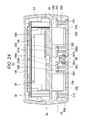
- FIG. 24 is a sectional view taken along line C-C in FIG. 18 .
- FIG. 25 is a sectional view corresponding to FIG. 15 of the first embodiment
- FIG. 26 is a front view of a speech communication device of a third embodiment
- FIG. 27 is an exploded perspective view showing a structure for housing microphones when a front surface of the speech communication device is directed upward;
- FIGS. 28A to 28D are exploded front views showing the structure for housing the microphones
- FIG. 28A shows a front view of a microphone housing recessed part (a front view of a microphone cover)
- FIG. 28B shows a front view of the microphone housing recessed part when the microphone cover in FIG. 28A is drawn transparent
- FIG. 28C shows a front view of the microphone housing recessed part when a microphone front face pressing sponge in FIG. 28B is drawn transparent
- FIG. 28D shows a front view of the microphone housing recessed part when a microphone fixing sponge, the microphones, and a microphone back face pressing sponge in FIG. 28C are drawn transparent;
- FIG. 29 is a sectional view taken along line A-A in FIG. 26 ;
- FIG. 30 is a sectional view taken along line B-B in FIG. 26 ;
- FIG. 31 is a sectional view corresponding to FIG. 15 of the first embodiment
- FIG. 32 is a front view of a speech communication device of a fourth embodiment
- FIG. 33 is an exploded perspective view showing a structure for housing microphones when a front surface of the speech communication device is directed upward;
- FIGS. 34A to 34C are exploded front views showing a structure for housing the microphones
- FIG. 34A shows a front view of a microphone housing recessed part (a front view of a microphone cover)
- FIG. 34B shows a front view of the microphone housing recessed part when the microphone cover in FIG. 34A is drawn transparent
- FIG. 34C shows a front view of the microphone housing recessed part when the microphones and microphone holders in FIG. 34B are drawn transparent;
- FIG. 35 is a sectional view taken along line A-A in FIG. 32 ;
- FIG. 36 is a sectional view taken along line B-B in FIG. 32 ;
- FIG. 37 is a sectional view taken along line C-C in FIG. 32 ;
- FIG. 38 is a sectional view corresponding to FIG. 15 of the first embodiment.
- FIG. 1 shows a schematic configuration diagram of an emergency call system 1 .
- a vehicle 2 is equipped with an emergency call device 10 , which can communicate by radio with an emergency call center 5 , and connects to the emergency call center 5 through a portable telephone network, a base station 3 in a public telephone line network, and a network 4 at a time of emergency so that the occupant can talk with an operator at the emergency call center 5 .
- the operator at the emergency call center 5 asks a fire department 6 , a police station 7 , or Japan Automobile Federation (JAF) 8 to hurry to the vehicle.
- JAF Japan Automobile Federation
- FIG. 2 shows a block diagram of the emergency call device 10 .
- the emergency call device 10 is controlled by an emergency call ECU 11 .
- the emergency call ECU 11 is connected to: a GPS receiver 12 which detects a position of the vehicle 2 , based on a radio wave from a GPS satellite; an air-bag switch 13 which detects an operation of an air-bag; a communication start switch 14 which is operated by the occupant to start a speech communication with the emergency call center 5 ; a communication device 15 used to connect to the emergency call center 5 ; and a hands-free speech communication device 20 for an emergency call system of a speaker and microphone integrated type (hereinafter, referred to as a “speech communication device”) of the present embodiment in which a speaker SP and a microphone M are housed together in the same housing 30 .
- a speech communication device a speaker and microphone integrated type
- the emergency call ECU 11 is configured as a computer equipped with a CPU, a ROM, a RAM, and an input/output interface.
- the communication device 15 is, for example, a data communication unit with a speech function or an occupant's smartphone.
- the communication device 15 can establish a data link according to, for example, the PPP protocol to send and receive data through the network 4 and through the upper layer TCP/IP protocol or the like.
- a data set is automatically transferred to the emergency call center 5 , and the data set includes information such as a vehicle model and a fuel type previously registered in the emergency call ECU 11 , position information of the vehicle 2 acquired by the GPS receiver 12 , and the like.
- the emergency call ECU 11 and the communication device 15 are detachably connected to each other by wire or radio.
- wire When connected by wire, a USB cable is used for connection, for example; and when connected by radio, the Bluetooth (registered trade mark) communication standard is used for connection, for example.
- the emergency call ECU 11 is equipped with an input device such as a switch, and in response to a user's operation on the input device, the emergency call ECU 11 performs a process to relay the on-hook/off-hook instruction to the communication device 15 and to make the communication device 15 perform an on-hook/off-hook operation.
- an input device such as a switch
- the emergency call ECU 11 sets the previously registered phone number as a connection destination and then connects to the emergency call center 5 .
- the communication device 15 outputs to the emergency call ECU 11 a reception sound signal received from the emergency call center 5 through the network 4 and transmits a transmission sound signal input from the emergency call ECU 11 to the emergency call center 5 through the network 4 .
- the emergency call ECU 11 outputs the reception sound signal input from the communication device 15 to the speech communication device 20 and outputs a transmission sound signal input from the speech communication device 20 to the communication device 15 .
- FIG. 3 shows how the speech communication device 20 is installed.
- the speech communication device 20 is disposed at a ceiling central part 2 c between the left sun visor 2 a and the right sun visor 2 b in a vehicle cabin.
- the drawing shows an example in which the speech communication device 20 is built into an overhead console 2 d at the ceiling central part 2 c .
- a sound passage (air passage) 2 e for emitting a reception sound output from the speaker SP of the speech communication device 20 into the vehicle cabin and for causing the microphone M of the speech communication device 20 to collect a sound spoken by an occupant.
- FIGS. 4A and 4B show exploded perspective views of the speech communication device 20
- FIG. 5 shows a front view of the speech communication device 20
- FIG. 6 shows a side view of the speech communication device 20
- FIG. 7 shows a sectional view taken along line A-A in FIG. 5
- FIG. 8 shows a sectional view taken along line B-B in FIG. 5
- FIG. 9 shows a sectional view taken along line C-C in FIG. 5 .
- the speech communication device 20 is configured mainly with the housing 30 defining an outline of the speech communication device 20 (a box shape of width 60 mm ⁇ height 65 mm ⁇ depth 30 mm) and with the speaker SP, the microphone M, and the sound processor 100 housed in the housing 30 .
- the housing 30 is configured with a front case 40 and a rear case 50 .
- the front case 40 is made by molding insulating synthetic resin material and includes a rectangular front face plate (front surface plate) 41 and a rectangular frame-shaped side wall 42 rising backward (toward the back surface side) from a peripheral edge of the front face plate 41 .
- the rear case 50 is made by molding insulating synthetic resin material and includes a rectangular rear face plate (rear surface plate) 51 and a rectangular frame-shaped side wall 52 rising forward (toward the front surface side) from a peripheral edge of the rear face plate 51 .
- the speaker SP, the microphone M, and the sound processor 100 are mounted on the front case 40 , and the front case 40 and the rear case 50 are connected and fixed to make up the housing 30 in the state that a connection cable (not shown) drawn from a printed circuit board 104 , on which the sound processor 100 is assembled, is drawn to the outside through a cable leading hole 43 provided in the side wall 42 of the front case 40 , in other words, at the end of the assemble process of the speech communication device 20 , so that the speech communication device 20 is assembled.
- the front case 40 and the rear case 50 are fixed by fastening the four corners of each of the two cases with four tapping screws (not shown).
- the speaker SP outputs from a front surface of the housing 30 a reception sound of a communication party (an operator at the emergency call center 5 ) and is mounted, as shown in FIG. 5 and FIG. 7 , on the inside of the front face plate 41 of the front case 40 so as to face the front surface of the housing 30 , in other words, to face a circular sound emission hole 44 provided in the front case 40 .
- the speaker SP is equipped, as shown in FIG. 7 , with a cylindrical frame 60 in which a cylindrical magnetic circuit holder 60 b having a smaller diameter than a vibration system holder 60 a is integrally molded on a rear edge of the cylindrical vibration system holder 60 a .
- a vibration system is made up of: a dome-shaped diaphragm 61 with a diameter of 40 mm whose outer circumference edge part is fixed on a front-end opening of the vibration system holder 60 a ; a cylindrical bobbin 62 fixed on a rear surface of the diaphragm 61 ; and a voice coil 63 provided on a rear end of the bobbin 62 , so that the vibration system can vibrate in a front and back direction.
- the speaker SP is configured with the vibration system and the magnetic circuit fixed on the magnetic circuit holder 60 b by fitting.
- the magnetic circuit is configured as an inner and outer magnet type with: a disc-shaped yoke 64 ; a cylinder-shaped inner permanent magnet 65 fixedly mounted at a central part of a yoke 64 ; a circular ring-shaped outer permanent magnet 66 fixedly mounted on an outer side of the yoke 64 and disposed to have a predetermined gap on the periphery of the inner permanent magnet 65 ; a disc-shaped inner polepiece 67 fixedly mounted on the inner permanent magnet 65 ; and a circular ring-shaped outer polepiece 68 fixedly mounted on the outer permanent magnet 66 and disposed to have a predetermined gap on an periphery of the inner polepiece 67 .
- a magnetic gap 69 is formed between the inner permanent magnet 65 and the outer permanent magnet 66 , and the voice coil 63 is disposed in the magnetic gap 69 .
- the front end of the vibration system holder 60 a of the frame 60 is fit in a plurality of arc-shaped ribs 45 for mounting the speaker SP which are protrudingly provided on the periphery of the sound emission hole 44 from an inner surface of the front face plate 41 of the front case 40 and fixed with an adhesive; thus, the speaker SP is mounted on the front case 40 through the frame 60 such that a front face of the diaphragm 61 is opposite to the sound emission hole 44 .
- a pair of lead wires (not shown) drawn from the voice coil 63 is connected to the printed circuit board 104 on which the sound processor 100 (to be described later) is mounted, and when a reception sound signal is input to the voice coil 63 from the sound processor 100 through the lead wires, an electromagnetic force is generated on the voice coil 63 by a current of the reception sound signal and a magnetic field of the inner and outer permanent magnets 65 and 66 ; thus, the bobbin 62 is vibrated together with the diaphragm 61 in the front and back direction. At this time, a reception sound depending on the reception sound signal is emitted from the diaphragm 61 to the front of the housing 30 through the sound emission hole 44 . That is, an electrodynamic speaker SP is configured.
- the electrodynamic speaker SP is equipped with, as the magnetic circuit, a magnetic circuit of the inner and outer magnet type, and it is thus easy to obtain a high sound pressure level than a magnetic circuit of the inner magnet type or the outer magnet type; therefore, the electrodynamic speaker SP is preferable as the speaker SP which outputs a reception sound of a communication party (an operator at the emergency call center 5 ) at a time of emergency.
- the magnetic circuit may be of the inner magnet type or the outer magnet type.
- a center O of the diaphragm 61 which is the center of the speaker SP, is disposed as shown in FIG. 5 at a position on a centerline CL of the width direction of the housing 30 when the speech communication device 20 is viewed from the front side. Further, the sound emission hole 44 is disposed at a coaxial position with the diaphragm 61 . In addition, line A-A in FIG. 5 coincides with the centerline CL.
- the microphone M collects sounds through the front surface of the housing 30 and is configured with three of first, second, and third omnidirectional microphones M 1 , M 2 , and M 3 as shown in FIG. 5 and FIGS. 7 to 9 .
- These first, second, and third omnidirectional microphones M 1 , M 2 , and M 3 (hereinafter, simply referred to as the “microphone M 1 ,” the “microphone M 2 ,” and the “microphone M 3 ”) each have the same configuration.
- FIG. 10 shows the configuration of the microphones M 1 , M 2 , and M 3 .
- Each of the microphones M 1 , M 2 , and M 3 is configured as an electret condenser microphone of a back electret type with a diameter of 4 mm and the thickness of 1.5 mm.
- a ring 71 disposed on a printed circuit board 70 supports an electrode 72 made of brass, and a brass ring 73 is provided between the electrode 72 and the printed circuit board 70 .
- a vibration film 74 made of Teflon (registered trade mark) is disposed to face the electrode 72 , and a vibration film 74 is supported by a brass ring 75 .
- a spacer 76 In an air gap formed between the electrode 72 and the vibration film 74 , there is provided a spacer 76 . Further, a case 77 above the printed circuit board 70 covers the above respective components, so that an outline of an electret condenser microphone is formed, and an amplified sound signal is output through a junction FET 78 disposed on the printed circuit board 70 .
- Such microphones M 1 , M 2 , and M 3 each have a diaphragm 74 disposed in the vicinity of and parallel to the electrode 72 , and the electrode 72 is configured with an electret film in which electric charge is enclosed (in other words, charged). Then, when an external acoustic signal vibrates the diaphragm 74 in the two directions each perpendicular to the printed circuit board 70 (the vertical direction in FIG. 10 ), the distance between the diaphragm 74 and the electrode 72 fluctuates, and the capacitance between the diaphragm 74 and the electrode 72 thus changes depending on the acoustic signal.
- the electrode 72 is made of a metal film such as a brass film or a plastic film to which metal is attached by a vapor deposition process or another process and to which electric charge is injected by a corona discharge process or the like and which has a property to semi-permanently hold the electric charge.
- the microphone cover 80 is formed by molding insulating synthetic resin material.
- the microphones M 1 and M 2 are disposed at the positions which are axisymmetric with the centerline CL in the width direction of the housing 30 as a symmetric axis, and the microphone M 3 is disposed on the symmetric axis at a position which is closer to the speaker SP than the microphones M 1 and M 2 are.
- the centerline CL in the width direction of the housing 30 corresponds to a line segment extending in the radial direction from the center O of the diaphragm 61 of the speaker SP.
- FIG. 11 is an exploded perspective view showing a structure for housing the microphones M 1 , M 2 , and M 3 when the front surface of the speech communication device 20 is directed upward
- FIG. 12 shows an exploded perspective view, viewed from below, of the microphone cover 80 , the microphone holders 90 a , 90 b , and 90 c , and the microphones M 1 , M 2 , and M 3
- FIGS. 13A to 13C are front views showing a structure for housing the microphones M 1 , M 2 , and M 3
- FIG. 13A shows a front view of the microphone housing recessed part 46 (a front view of the microphone cover)
- FIG. 13B shows a front view of the microphone housing recessed part 46 when the microphone cover 80 in FIG.
- FIG. 13A is drawn transparent
- FIG. 13C shows a front view of the microphone housing recessed part 46 when the microphone holders 90 a , 90 b , and 90 c and the microphones M 1 , M 2 , and M 3 in FIG. 13B are drawn transparent.
- the microphone housing recessed part 46 is formed, above the sound emission hole 44 in the front surface of the housing 30 , in a rectangular recessed part such that the microphone cover 80 formed in a rectangular plate-shape is closely fit therein; and in the bottom of the rectangular recessed part, there are provided: three of first, second, and third microphone housing parts 47 a , 47 b , and 47 c (hereinafter, simply referred to as the “microphone housing part 47 a ,” the “microphone housing part 47 b ,” and the “microphone housing part 47 c ”) each constituted by a circular-shaped recessed part for housing each of the microphones M 1 , M 2 , and M 3 ; and a plurality of recessed parts 48 into which a plurality of boss parts 82 protrudingly provided from the inner surface of the microphone cover 80 for screw fixing are to be inserted.
- first, second, and third lead wire holes 49 a , 49 b , and 49 c (hereinafter, simply referred to as the “lead wire hole 49 a ,” the “lead wire hole 49 b ,” and the “lead wire hole 49 c ”) for drawing lead wires (not shown) led from the printed circuit boards 70 of the microphones M 1 , M 2 , and M 3 into the inner surface side of the housing 30 (the inner surface side of the front face plate 41 of the front case 40 ); and on the bottom surfaces of the recessed parts 48 , there are provided bolt insertion holes 48 a.
- the microphones M 1 , M 2 , and M 3 are housed in the microphone housing parts 47 a , 47 b , and 47 c in such postures that the diaphragms 74 of the microphones M 1 , M 2 , and M 3 vibrate in the same direction as the vibration direction of the diaphragm 61 of the speaker SP (the front and back direction) and that sound collection surfaces of the microphones M 1 , M 2 , and M 3 are provided to face the same direction as the sound direction output from the speaker SP (the forward direction).
- the microphone cover 80 is fit into the microphone housing recessed part 46 from the front surface side of the housing 30 to fix the microphone cover 80 on the housing 30 ; thus, the microphones M 1 , M 2 , and M 3 are disposed to be held in the microphone housing recessed part 46 at the above-described positions and in the above-described postures while the microphones M 1 , M 2 , and M 3 are pressed by the inner surface of the microphone cover 80 and while the sound collection holes 81 a , 81 b , and 81 c are opposite to the sound collection surfaces of the microphones M 1 , M 2 , and M 3 .
- the microphone cover 80 is fixed by screwing in tapping screws (not shown) from behind the front face plate 41 of the front case 40
- the first, second, and third cylindrical microphone holders 90 a , 90 b , and 90 c which are made of a resilient rubber material (elastomer) and are housed in the microphone housing parts 47 a , 47 b , and 47 c together with the microphones M 1 , M 2 , and M 3 while being fit on the outer circumferences on the microphones M 1 , M 2 , and M 3 and being held between the outer circumferential surfaces of the microphones M 1 , M 2 , and M 3 and the microphone housing parts 47 a , 47 b , and 47 c ; thus, the microphone holders 90 a , 90 b , and 90 c can absorb and reduce the vibration transferred from the speaker SP to the microphones M 1 , M 2 , and M 3 through the housing 30 .
- a resilient rubber material elastomer
- FIGS. 14A and 14B are diagram each showing an inner surface of the housing 30
- FIG. 14A is a rear view of the front case 40
- FIG. 14B is a front view of the rear case 50
- FIG. 15 shows a sectional view taken along line D-D in FIG. 6 .
- honeycomb reinforcement ribs 40 a On the inner surface of the front face plate 41 of the front case 40 and on the periphery of the arc-shaped ribs 45 for mounting the speaker, there are provided honeycomb reinforcement ribs 40 a as shown in FIG. 14A and FIG. 15 ; and also on the inner surface of the rear face plate 51 of the rear case 50 , there are provided honeycomb reinforcement ribs 50 a .
- the reinforcement ribs 40 a and 50 a increase stiffness of the housing 30 , and it is thus possible to reduce the vibration transferred from the speaker SP to the microphones M 1 , M 2 , and M 3 through the housing 30 .
- FIG. 16 shows a circuit configuration diagram of the sound processor 100 .
- the sound processor 100 is configured with an IC equipped with an amplifier 101 , the beam former 102 , and an echo cancel unit 103 , and a reception sound signal received by the communication device 15 and input through the emergency call ECU 11 is amplified by the amplifier 101 and is then output from the speaker SP. Further, sound signals input from the microphones M 1 , M 2 , and M 3 are subjected to signal processing (to be described later) on the beam former 102 and the echo cancel unit 103 and are then output to the communication device 15 through the emergency call ECU 11 , thereby being transmitted to the emergency call center 5 .
- the beam former 102 is connected to the microphones M 1 and M 2 and is equipped with: a delay unit 102 a which delays the output from one microphone M 2 by the time period corresponding to the distance X (43 mm in the present embodiment) between the centers of the sound collection surfaces of the microphone M 1 and M 2 ; and an accumulator 102 b which adds the output from the delay unit 102 a to the output from the other microphone M 1 ; thus, as shown in FIG.
- the beam former 102 forms a bidirectionality 102 c in which the directionality is strong in the two directions perpendicular to the centerline CL in the width direction of the housing 30 (the width direction of the housing 30 and the right and left direction in the arrangement direction of the microphone M 1 and M 2 ) and the directionality is weak in the two directions along the centerline CL in the width direction of the housing 30 (the height direction of the housing 30 and the vertical direction in the arrangement direction of the speaker SP and the microphone M).
- the distance from the center O of the diaphragm 61 of the speaker SP to an intersection point between a straight line connecting the centers of the sound collection surfaces of the microphones M 1 and M 2 and the centerline CL in the width direction of the housing 30 is 31.5 mm.
- the sound processor 100 is housed in the housing 30 , being mounted on the printed circuit board 104 .
- the printed circuit board 104 is mounted on the front case 40 and is housed in a gap between a rear end of the speaker SP in the housing 30 and the rear face plate 51 of a rear case 50 , as shown in FIGS. 7 to 9 .
- the speech communication device 20 is disposed in the following manner; the front surface of the housing 30 (the outer surface of the front face plate 41 of the front case 40 ) is directed downward to face a sound passing part 2 e right under the front surface of the housing 30 ; the microphone M is located behind the speaker SP with the front side surface and the rear side surface of the housing 30 being directed in the front and back direction of the vehicle 2 ; and the centerline CL in the width direction of the housing 30 extends in the front and back direction of the vehicle 2 .
- a speech communication device 20 of the present embodiment includes: a housing 30 disposed in a vehicle cabin; a speaker SP which is housed in the housing 30 and outputs from a front surface of the housing 30 a reception sound of a communication party; and a microphone M which is housed in the housing 30 and collects sounds from the front surface of the housing 30 .
- the microphone M is constituted by: first and second microphones M 1 and M 2 disposed at positions which are axisymmetric with a centerline CL in the width direction of the housing 30 as a symmetric axis; and a third microphone M 3 disposed at a position which is on the centerline CL and is closer to the speaker SP than the first and second microphones M 1 and M 2 are.
- the speech communication device 20 further includes a sound processor 100 which includes: a beam former 102 which is connected to the first and second microphones M 1 and M 2 and forms a bidirectionality 102 c in which directionality is strong in two directions each perpendicular to the centerline CL and is weak in two directions each along the centerline CL; and an echo cancel unit 103 which is connected to the beam former 102 and the third microphone M 3 and removes a sound signal having been output from the third microphone M 3 from a sound signal having been output from the beam former 102 .
- a sound processor 100 which includes: a beam former 102 which is connected to the first and second microphones M 1 and M 2 and forms a bidirectionality 102 c in which directionality is strong in two directions each perpendicular to the centerline CL and is weak in two directions each along the centerline CL; and an echo cancel unit 103 which is connected to the beam former 102 and the third microphone M 3 and removes a sound signal having been output from the third microphone M 3 from a sound signal having been output from
- the sound processor 100 causes the beam former 102 connected to the first and second microphones M 1 and M 2 to form the bidirectionality 102 c in which directionality is strong in the two directions each perpendicular to the centerline CL and is weak in the two direction each along the centerline CL, in other words, the sound processor 100 weakens the directionality of the microphone M 1 and M 2 in the direction toward the speaker SP; therefore, it is possible to reduce an echo coming into the microphones M 1 and M 2 from the speaker SP.
- the sound processor 100 causes the echo cancel unit 103 connected to the beam former 102 and the third microphone M 3 to remove the sound signal having been output from the third microphone M 3 from the sound signal having been output from the beam former 102 ; therefore, it is possible to extract only a voice generated by an occupant with high quality.
- the housing 30 is disposed at a ceiling central part 2 c between a left sun visor 2 a and a right sun visor 2 b in the vehicle cabin such that the front surface of the housing 30 is directed downward, the microphone M is located behind the speaker SP, and the centerline CL extends in the front and back direction of the vehicle 2 .
- the directionality is weakened in the front and back direction viewed from the ceiling central part 2 c between the left sun visor 2 a and the right sun visor 2 b in the vehicle cabin and is strengthened in the right and left direction; therefore, it is possible to collect voices of the occupants behind the wheel and in the passenger's seat.
- a sound emission hole 44 provided at a position facing the diaphragm 61 of the speaker SP; a microphone housing recessed part 46 which houses the microphone M; a microphone cover 80 which covers the microphone housing recessed part 46 ; and sound collection holes 81 a , 81 b , and 81 c provided in the microphone cover 80 .
- This arrangement enables the microphone M to be put into the microphone housing recessed part 46 from the front surface side of the housing 30 ; therefore, it is easy to assemble.
- microphone housing recessed part 46 there are provided microphone housing parts 47 a , 47 b , and 47 c each of which separately houses each of the microphones M 1 , M 2 , and M 3 .
- This arrangement enable the microphones M 1 , M 2 , and M 3 to be easily positioned.
- microphone holders 90 a , 90 b , and 90 c which are made of a resilient rubber material and are respectively housed, together with the microphones M 1 , M 2 , and M 3 , in the first, second, and third microphone housing parts 47 a , 47 b , and 47 c such that the microphone holders 90 a , 90 b , and 90 c are respectively held between outer circumferential surfaces of the microphones M 1 , M 2 , and M 3 and inner peripheral surfaces of the first, second, and third microphone housing parts 47 a , 47 b , and 47 c while being fit on outer circumferences of the microphones M 1 , M 2 , and M 3 .
- this arrangement it is possible to reduce the vibration transferred from the speaker SP to the microphones M 1 , M 2 , and M 3 through the housing 30 by means of the microphone holders 90 a , 90 b , and 90 c.
- FIG. 18 shows a front view of a speech communication device 200 of a second embodiment.
- FIG. 19 shows an exploded perspective view showing a structure for housing microphones M 1 , M 2 , and M 3 when a front surface of the speech communication device 200 is directed upward.
- FIG. 20 shows an exploded perspective view, viewed from below, of a microphone cover 280 , microphone holders 90 a , 90 b , and 90 c , the microphones M 1 , M 2 , and M 3 , a fixing plate 203 , and cushion members 202 in FIG. 19 .
- FIGS. 21A to 21D show exploded front views showing a structure for housing the microphones M 1 , M 2 , and M 3 , FIG.
- FIG. 21A shows a front view of a microphone housing recessed part 246 (a front view of the microphone cover 280 )
- FIG. 21B shows a front view of the microphone housing recessed part 246 when the microphone cover 280 in FIG. 21A is drawn transparent
- FIG. 21C shows a front view of the microphone housing recessed part 246 when the microphone holders 90 a , 90 b , and 90 c and the microphones M 1 , M 2 , and M 3 in FIG. 21B are drawn transparent
- FIG. 21D shows a front view of the microphone housing recessed part 246 when the fixing plate 203 and the cushion members 202 in FIG. 21C are drawn transparent.
- FIG. 22 shows a sectional view taken along line A-A in FIG. 18 , FIG.
- FIG. 23 shows a sectional view taken along line B-B in FIG. 18
- FIG. 24 shows a sectional view taken along line C-C in FIG. 18
- a side view of the speech communication device 200 is identical to the side view shown in FIG. 6 of the first embodiment.
- FIG. 25 is a sectional view corresponding to FIG. 15 (the sectional view taken along line D-D in FIG. 6 ) of the first embodiment.
- the microphone cover 280 is formed in a rectangular shape a little smaller than the shape of an opening of the microphone housing recessed part 246 so that a gap 201 will be created around the microphone cover 280 so as to prevent the microphone cover 280 from being in contact with the housing 30 when the microphone cover 280 is put in the microphone housing recessed part 246 .
- the microphones M 1 , M 2 , and M 3 are attached to the microphone cover 280 , and the microphone cover 280 is fixed on the microphone housing recessed part 246 with cushion members 202 each of which has adhesiveness on the both sides. With this arrangement, the vibration transferred from the speaker SP to the microphones M 1 , M 2 , and M 3 through the housing 30 is reduced by means of the cushion members 202 .
- the microphones M 1 , M 2 , and M 3 are attached to the microphone cover 280 in such a manner that the microphones M 1 , M 2 , and M 3 are held between the microphone cover 280 and the fixing plate 203 which is provided on the back surface side of the microphone cover 280 and is to be fixed thereon with a predetermined distance therebetween.
- the fixing plate 203 is formed by molding insulating synthetic resin material.
- first, second, and third sound collection holes 281 a , 281 b , and 281 c (hereinafter, simply referred to as the “sound collection hole 281 a ,” the “sound collection hole 281 b ,” and the “sound collection hole 281 c ”) provided in the microphone cover 280 , there are protrudingly provided three of first, second, and third cylindrical boss parts 282 a , 282 b , and 282 c (hereinafter, simply referred to as the “boss part 282 a ,” the “boss part 282 b ,” and the “boss part 282 c ”); and in rear end faces of the boss parts 282 a , 282 b , and 282 c , in the axis direction, there are provided three of first, second, and third microphone housing parts 247 a , 247 b , and 247 c (her
- the fixing plate 203 On a front surface of the fixing plate 203 facing the inner surface of the microphone cover 280 , at three positions facing the microphone housing parts 247 a , 247 b , and 247 c , there are protrudingly provided three of first, second, and third microphone pressing parts 206 a , 206 b , and 206 c (hereinafter, simply referred to as the “microphone pressing part 206 a ,” the “microphone pressing part 206 b ,” and the “microphone pressing part 206 c ”) which are constituted by projecting parts. Further, in the fixing plate 203 , there are provided a plurality of positioning holes 207 corresponding to the positioning pins 204 and a plurality of bolt insertion holes 208 corresponding to the boss parts 205 for screw fixing.
- the microphones M 1 , M 2 , and M 3 are housed in the microphone housing parts 247 a , 247 b , and 247 c of the microphone cover 280 , and the fixing plate 203 is then parallely fixed on the back surface side of the microphone cover 280 with a predetermined distance therebetween; thus, the microphones M 1 , M 2 , and M 3 are pressed by the end faces of the microphone pressing parts 206 a , 206 b , and 206 c of the fixing plate 203 and are held in the microphone housing parts 247 a , 247 b , and 247 c of the microphone cover 280 such that the sound collection surfaces of the microphones M 1 , M 2 , and M 3 are opposite to the sound collection holes 281 a , 281 b , and 281 c of the microphone cover 280 .
- the microphones M 1 , M 2 , and M 3 are housed in the microphone housing parts 247 a , 247 b , and 247 c of the microphone cover 280 with the microphone holders 90 a , 90 b , and 90 c being fit on the outer circumferences of the microphones M 1 , M 2 , and M 3 .
- the fixing plate 203 is fixed on the microphone cover 280 by screwing in tapping screws (not shown) from the back surface side of the fixing plate 203 through the bolt insertion holes 208 into the boss parts 205 of the microphone cover 280 while the positioning pins 204 of the microphone cover 280 are positioned being fit in the positioning holes 207 of the fixing plate 203 .
- the microphone cover 280 is put into the microphone housing recessed part 246 from the front surface side of the housing 30 (from ahead of the front face plate 41 of the front case 40 ) so as to fix the microphone cover 80 on the housing 30 ; thus, the microphones M 1 , M 2 , and M 3 are disposed to be housed in the microphone housing recessed part 46 of the housing 30 at the same position and in the same posture as in the first embodiment.
- cover abutting parts 209 on three positions which include a position on an upper central part and two positions on lower both end parts on a peripheral wall part of the microphone housing recessed part 246 , and the cover abutting parts 209 are provided to have a constant width to support the microphone cover 280 at the opening of the microphone housing recessed part 246 so that, when the microphone cover 280 is put into the microphone housing recessed part 246 , an outer peripheral part of the inner surface of the microphone cover 280 will be in contact with the cover abutting parts 209 and the outer surface of the microphone cover 280 is flush with the front surface of the housing 30 .
- Front end surfaces of the cover abutting parts 209 are stuck with the cushion members 202 each having a tape-like shape with a constant width and adhesiveness on the both sides.
- the cushion members 202 are formed by, for example, sticking two-sided adhesive tapes on or applying adhesive to both sides of a tape-like spongy base material with a constant width so as to form adhesive layers.
- the microphone cover 280 is put into the microphone housing recessed part 246 from the front surface side of the housing 30 ; thus, the outer peripheral part of the inner surface of the microphone cover 280 is adhered to the cushion members 202 . Because the microphone cover 280 is fixed on the microphone housing recessed part 246 with the cushion members 202 and because the microphone cover 280 is not directly in contact with the housing 30 , the vibration transferred from the speaker SP to the microphones M 1 , M 2 , and M 3 through the housing 30 is reduced.
- the fixing plate 203 is formed in the same rectangular shape as the microphone cover 280 so that the fixing plate 203 will not be in contact with the housing 30 when put in the microphone housing recessed part 246 together with the microphone cover 280 . Further, in the outer edge part of the microphone cover 280 , there are provided notch parts 210 so as to prevent the microphone cover 280 from interfering (being in contact) with the cover abutting part 209 .
- first, second, and third lead wire holes 211 a , 211 b , and 211 c (hereinafter, simply referred to as the “lead wire hole 211 a ,” the “lead wire hole 211 b ,” and the “lead wire hole 211 c ”) through which lead wires of the microphones M 1 , M 2 , and M 3 are drawn out to a bottom part of the microphone housing recessed part 246 of the back surface side of the fixing plate 203 ; and in a bottom surface of the microphone housing recessed part 246 facing the back surface of the fixing plate 203 , there are provided three of first, second, and third lead wire holes 249 a , 249 b , and 249 c to face the lead wire holes 211 a , 211 b , and 211 c so that the lead wires of the microphones M
- the microphone housing parts 247 a , 247 b , and 247 c are provided on the microphone cover 280 so as to separately house the microphones M 1 , M 2 , and M 3 such that the microphone housing parts 247 a , 247 b , and 247 c protrude from the inner surface of the microphone cover 280 , the cushion members 202 are provided to have adhesiveness on the both sides so as to fix the microphone cover 280 on the microphone housing recessed part 246 , and the gap 201 is provided between the microphone housing recessed part 246 and the microphone cover 280 .
- the cushion members 202 With this arrangement, it is possible to reduce the vibration transferred from the speaker SP to the microphones M 1 , M 2 , and M 3 through the housing 30 by means of the cushion members 202 .
- FIG. 26 shows a front view of a speech communication device 300 of a third embodiment.
- FIG. 27 shows an exploded perspective view showing a structure for housing microphones M 1 , M 2 , and M 3 when a front surface of the speech communication device 300 is directed upward.
- FIGS. 28A to 28D show exploded front views showing a structure for housing the microphones M 1 , M 2 , and M 3 ,
- FIG. 28A shows a front view of a microphone housing recessed part 346 (a front view of a microphone cover 380 ),
- FIG. 28B shows a front view of the microphone housing recessed part 346 when the microphone cover 380 in FIG. 28A is drawn transparent, FIG.
- FIG. 28C shows a front view of the microphone housing recessed part 346 when a microphone front face pressing sponge 303 in FIG. 28B is drawn transparent
- FIG. 28D is a front view of the microphone housing recessed part 346 when a microphone fixing sponge 301 , the microphones M 1 , M 2 , and M 3 , and microphone back face pressing sponges 302 in FIG. 28C are drawn transparent
- FIG. 29 shows a sectional view taken along line A-A in FIG. 26
- FIG. 30 shows a sectional view taken along line B-B in FIG. 26
- a side view of the speech communication device 300 is identical to the side view shown in FIG. 6 of the first embodiment.
- FIG. 31 is a sectional view corresponding to FIG. 15 (the sectional view taken along line D-D in FIG. 6 ) of the first embodiment.
- a speech communication device 300 for an emergency call system of a speaker and microphone integrated type in which a speaker SP and a microphone M are housed in the same housing 30 , there is provided a block-like sponge 301 for fixing (positioning) a microphone, where the sponge 301 is an air permeable cushion member and is formed approximately in the same outer shape as the microphone housing recessed part 346 such that the sponge 301 can be fit into the microphone housing recessed part 346 in a free state.
- the microphone fixing sponge 301 there are provided three of first, second, and third microphone housing parts 347 a , 347 b , and 347 c (hereinafter, simply referred to as the “microphone housing part 347 a ,” the “microphone housing part 347 b ,” and the “microphone housing part 347 c ”), and the microphone housing parts 347 a , 347 b , and 347 c are constituted by circular through holes which have approximately the same diameters as the microphones M 1 , M 2 , and M 3 and can separately house the microphones M 1 , M 2 , and M 3 in a free state.
- the microphone fixing sponge 301 reduces the vibration transferred from the speaker SP to the microphones M 1 , M 2 , and M 3 through the housing 30 .
- cylinder-shaped microphone back face pressing sponges 302 which have approximately the same diameters as the microphones M 1 , M 2 , and M 3 and are put into the microphone housing parts 347 a , 347 b , and 347 c prior to the microphones M 1 , M 2 , and M 3 in a free state so as to press the back surfaces of the microphones M 1 , M 2 , and M 3 ; and plate-shaped microphone front face pressing sponge 303 which is formed to have approximately the same outer shape as the microphone housing recessed part 346 and is stacked in front of the microphone fixing sponge 301 so as to press sound collection surfaces (front surfaces) of the microphones M 1 , M 2 , and M 3 .
- the microphone fixing sponge 301 is put into the microphone housing recessed part 346 from the front surface side of the housing 30 (from ahead of the front face plate 41 of the front case 40 ), the microphone back face pressing sponges 302 is put into the microphone housing parts 347 a , 347 b , and 347 c of the microphone fixing sponge 301 , and the microphones M 1 , M 2 , and M 3 is put into the microphone housing parts 347 a , 347 b , and 347 c .
- the microphone cover 380 is put into the microphone housing recessed part 346 from the front surface side of the housing 30 , and the microphone cover 380 is then fixed on the housing 30 , so that the microphones M 1 , M 2 , and M 3 are disposed to be housed in the microphone housing recessed part 346 of the housing 30 at the same position and in the same posture as in the first embodiment.
- cover abutting parts 304 on a peripheral wall part of the microphone housing recessed part 346 , and the cover abutting parts 304 are provided to support the microphone cover 380 at an opening of the microphone housing recessed part 346 such that, when the microphone cover 380 is put into the microphone housing recessed part 346 from the front surface side of the housing 30 , an outer peripheral part of the inner surface of the microphone cover 380 is in contact with the cover abutting parts 304 and the outer surface of the microphone cover 380 is flush with the front surface of the housing 30 .
- the microphone cover 380 is fixed with two-sided adhesive tape (not shown) stuck to front end surfaces of the cover abutting parts 304 .
- the microphone cover 380 there are provided sound collection holes 381 constituted by many small holes on the area except the outer peripheral part of the microphone cover 380 .
- first, second, and third lead wire holes 349 a , 349 b , and 349 c to face rear end faces of the microphone back face pressing sponges 302 so that the lead wires of the microphones M 1 , M 2 , and M 3 can be drawn into the inner surface side (the inner surface side of the front face plate 41 of the front case 40 ) of the housing 30 .
- the air permeable microphone fixing sponge 301 which can be fit into the microphone housing recessed part 346 ; and in the microphone fixing sponge 301 , the microphone housing parts 347 a , 347 b , and 347 c are provided so as to separately house the microphones M 1 , M 2 , and M 3 .
- the microphone fixing sponge 301 can reduce the vibration transferred from the speaker SP to the microphones M 1 , M 2 , and M 3 through the housing 30 .
- FIG. 32 shows a front view of a speech communication device 400 of a fourth embodiment.
- FIG. 33 shows an exploded perspective view showing a structure for housing microphones M 1 , M 2 , and M 3 when a front surface of the speech communication device 400 is directed upward.
- FIGS. 34A to 34C show exploded front views showing a structure for housing the microphones M 1 , M 2 , and M 3 ,
- FIG. 34A shows a front view of a microphone housing recessed part 446 (a front view of a microphone cover 480 ),
- FIG. 34B shows a front view of the microphone housing recessed part 446 when the microphone cover 480 in FIG. 34A is drawn transparent, and
- FIG. 34A shows a front view of a speech communication device 400 of a fourth embodiment.
- FIG. 33 shows an exploded perspective view showing a structure for housing microphones M 1 , M 2 , and M 3 when a front surface of the speech communication device 400 is directed upward.
- FIGS. 34A to 34C show
- FIG. 34C shows a front view of the microphone housing recessed part 446 when the microphones M 1 , M 2 , and M 3 and microphone holders 90 a , 90 b , and 90 c in FIG. 34B are drawn transparent.
- FIG. 35 shows a sectional view taken along line A-A in FIG. 32
- FIG. 36 shows a sectional view taken along line B-B in FIG. 32
- FIG. 37 shows a sectional view taken along line C-C in FIG. 32 .
- a side view of the speech communication device 400 is approximately identical to the side view shown in FIG. 6 of the first embodiment.
- FIG. 38 is a sectional view corresponding to FIG. 15 (the sectional view taken along line D-D in FIG. 6 ) of the first embodiment.
- the microphones M 1 , M 2 , and M 3 are disposed such that the diaphragms 74 of the microphones vibrate in the same direction as the vibration direction of the diaphragm 61 of the speaker SP (the front and back direction).
- the microphones M 1 , M 2 , and M 3 are disposed to be housed in the microphone housing parts 47 a , 47 b , and 47 c ; 247 a , 247 b , and 247 c ; and 347 a , 347 b , and 347 c of the microphone housing recessed parts 46 , 246 , and 346 such that the sound collection surfaces (front surfaces) of the microphones M 1 , M 2 , and M 3 are directed toward the front surface of the housing 30 .
- the microphones M 1 , M 2 , and M 3 are disposed to be housed in the microphone housing recessed part 446 such that the diaphragms 74 of the microphones M 1 , M 2 , and M 3 vibrate in the direction perpendicular to the vibration direction of the diaphragm 61 of the speaker SP (a right and left direction and a vertical direction), in other words, such that the side surfaces of the microphones M 1 , M 2 , and M 3 are directed to the front surface of the housing 30 .
- This arrangement reduces the influence of the vibration transferred from the speaker SP to the microphones M 1 , M 2 , and M 3 through the housing 30 to the microphones M 1 , M 2 , and M 3 .
- the microphone housing recessed part 446 is formed, above the sound emission hole 44 in the front surface of the housing 30 , in a rectangular recessed part in which the microphone cover 480 formed in a rectangular plate-shape is closely fit.
- a rectangular recessed part in which the microphone cover 480 formed in a rectangular plate-shape is closely fit.
- the bottom of the rectangular recessed part there are provided: three of first, second, and third microphone housing parts 447 a , 447 b , and 447 c (hereinafter, simply referred to as the “microphone housing part 447 a ,” the “microphone housing part 447 b ,” and the “microphone housing part 447 c ”) which are constituted by recessed parts in rectangular shapes (the shapes when the housing 30 is viewed from the front surface) and respectively house the microphones M 1 , M 2 , and M 3 and the microphone holders 90 a , 90 b , and 90 c externally fit on the microphones M 1 , M 2 , and M 3 ;
- first, second, and third lead wire holes 449 a , 449 b , and 449 c for drawing lead wires (not shown) led from the printed circuit boards 70 of the microphones M 1 , M 2 , and M 3 into the inner surface side (the inner surface side of the front face plate 41 of the front case 40 ) of the housing 30 .
- sound collection holes 481 a , 481 b , and 481 c of the microphone cover 480 are provided at three positions facing the sound paths 301 a , 301 b , and 301 c.
- the microphone housing parts 447 a and 447 b for housing the microphones M 1 and M 2 for beamforming are formed such that the first side surfaces forming the sound paths 301 a and 301 b of the microphone housing parts 447 a and 447 b are formed to face each other in the width direction (right and left direction) of the housing 30 , and the microphones M 1 and M 2 are housed such that the sound collection surfaces of the microphones M 1 and M 2 face each other in the width direction of the housing 30 .
- the microphone housing part 447 c for housing the microphone M 3 for cancelling echo is formed such that the first side surface forming the sound path 301 c of the microphone housing part 447 c is directed in the direction opposite to the speaker SP (upward), and the microphone M 3 is housed with the back surface of the microphone M 3 directed to the side of the speaker SP (downward).
- the microphone cover 480 is fit into the microphone housing recessed part 446 from the front surface side of the housing 30 to fix the microphone cover 480 on the housing 30 ; thus, the microphones M 1 , M 2 , and M 3 are disposed to be held in the microphone housing recessed part 446 at the same positions as in the first embodiment while the microphones M 1 , M 2 , and M 3 are pressed by the inner surface of the microphone cover 480 and while the sound collection holes 81 a , 81 b , and 81 c are opposite to the sound paths 301 a , 301 b , and 301 c .
- the microphone cover 480 is fit into the microphone housing recessed part 446 from the front surface side of the housing 30 to fix the microphone cover 480 on the housing 30 ; thus, the microphones M 1 , M 2 , and M 3 are disposed to be held in the microphone housing recessed part 446 at the same positions as in the first embodiment while the microphones M 1 , M 2 , and M 3 are pressed by the
- the microphones M 1 , M 2 , and M 3 are disposed such that the diaphragms 74 of the microphones M 1 , M 2 , and M 3 vibrate in the direction perpendicular to the vibration direction of the diaphragm 61 of the speaker SP (a right and left direction and a vertical direction).
- This arrangement can reduce influence of the vibration transferred from the speaker SP to the microphones M 1 , M 2 , and M 3 through the housing 30 to the microphones M 1 , M 2 , and M 3 .
Landscapes
- Engineering & Computer Science (AREA)
- Signal Processing (AREA)
- Computer Networks & Wireless Communication (AREA)
- General Physics & Mathematics (AREA)
- Remote Sensing (AREA)
- Physics & Mathematics (AREA)
- Radar, Positioning & Navigation (AREA)
- Mechanical Engineering (AREA)
- Telephone Function (AREA)
- Telephone Set Structure (AREA)
- Fittings On The Vehicle Exterior For Carrying Loads, And Devices For Holding Or Mounting Articles (AREA)
- Details Of Audible-Bandwidth Transducers (AREA)
- Obtaining Desirable Characteristics In Audible-Bandwidth Transducers (AREA)
- Circuit For Audible Band Transducer (AREA)
Applications Claiming Priority (2)
| Application Number | Priority Date | Filing Date | Title |
|---|---|---|---|
| JP2016142334A JP6634354B2 (ja) | 2016-07-20 | 2016-07-20 | 緊急通報システム用ハンズフリー通話装置 |
| JP2016-142334 | 2016-07-20 |
Publications (2)
| Publication Number | Publication Date |
|---|---|
| US20180027369A1 US20180027369A1 (en) | 2018-01-25 |
| US9913084B2 true US9913084B2 (en) | 2018-03-06 |
Family
ID=59315424
Family Applications (1)
| Application Number | Title | Priority Date | Filing Date |
|---|---|---|---|
| US15/650,086 Active US9913084B2 (en) | 2016-07-20 | 2017-07-14 | Hands-free speech communication device for an emergency call system |
Country Status (6)
| Country | Link |
|---|---|
| US (1) | US9913084B2 (fr) |
| EP (1) | EP3273671B1 (fr) |
| JP (1) | JP6634354B2 (fr) |
| KR (1) | KR102187061B1 (fr) |
| CN (1) | CN107645584B (fr) |
| TW (1) | TWI722150B (fr) |
Cited By (2)
| Publication number | Priority date | Publication date | Assignee | Title |
|---|---|---|---|---|
| EP4009658A1 (fr) * | 2020-12-01 | 2022-06-08 | Alps Alpine Co., Ltd. | Dispositif d'émission sonore d'un véhicule |
| US11689850B2 (en) | 2018-10-11 | 2023-06-27 | Semiconductor Energy Laboratory Co., Ltd. | Sound source separation device, semiconductor device, and electronic device |
Families Citing this family (4)
| Publication number | Priority date | Publication date | Assignee | Title |
|---|---|---|---|---|
| JP6528975B2 (ja) * | 2016-04-19 | 2019-06-12 | マツダ株式会社 | 緊急通報装置及び緊急通報システム |
| WO2018216694A1 (fr) * | 2017-05-24 | 2018-11-29 | 株式会社トランストロン | Dispositif embarqué |
| EP3650275B1 (fr) * | 2018-11-06 | 2024-02-28 | Harman Becker Automotive Systems GmbH | Microphone invisible de ciel de toit |
| JP7139272B2 (ja) * | 2019-03-20 | 2022-09-20 | 株式会社トランストロン | 車載装置 |
Citations (5)
| Publication number | Priority date | Publication date | Assignee | Title |
|---|---|---|---|---|
| US20030063759A1 (en) * | 2001-08-08 | 2003-04-03 | Brennan Robert L. | Directional audio signal processing using an oversampled filterbank |
| US20070165875A1 (en) * | 2005-12-01 | 2007-07-19 | Behrooz Rezvani | High fidelity multimedia wireless headset |
| JP2009290789A (ja) | 2008-05-30 | 2009-12-10 | Toyota Motor Corp | 緊急通報システム、緊急通報方法 |
| US20150016642A1 (en) * | 2013-07-15 | 2015-01-15 | Dts, Inc. | Spatial calibration of surround sound systems including listener position estimation |
| US20160275961A1 (en) * | 2015-03-18 | 2016-09-22 | Qualcomm Technologies International, Ltd. | Structure for multi-microphone speech enhancement system |
Family Cites Families (22)
| Publication number | Priority date | Publication date | Assignee | Title |
|---|---|---|---|---|
| JP2000184051A (ja) * | 1998-12-15 | 2000-06-30 | Nec Corp | 音声会議装置及び集音方法 |
| GB2367730B (en) * | 2000-10-06 | 2005-04-27 | Mitel Corp | Method and apparatus for minimizing far-end speech effects in hands-free telephony systems using acoustic beamforming |
| JP4161685B2 (ja) * | 2002-11-11 | 2008-10-08 | 株式会社デンソー | 音声入出力装置 |
| JP2004309536A (ja) * | 2003-04-02 | 2004-11-04 | Tokai Rika Co Ltd | 音声処理装置 |
| JP4966658B2 (ja) * | 2003-05-19 | 2012-07-04 | ジェンテックス コーポレイション | ハンドフリー電話機構成要素を組み込んだバックミラー・アセンブリ |
| US7403611B1 (en) * | 2004-04-13 | 2008-07-22 | Fortemedia, Inc. | Small size hands-free speakerphone apparatus |
| JP4802808B2 (ja) * | 2006-03-28 | 2011-10-26 | パナソニック電工株式会社 | 通話装置 |
| JP2007336132A (ja) * | 2006-06-14 | 2007-12-27 | Matsushita Electric Ind Co Ltd | エコー抑圧装置 |
| CN101198235B (zh) * | 2006-12-08 | 2011-05-18 | 美商富迪科技股份有限公司 | 电子装置以及将麦克风安装于该电子装置中的方法 |
| JP4700673B2 (ja) * | 2007-11-15 | 2011-06-15 | 日本電信電話株式会社 | エコー消去方法、装置、プログラム、および記録媒体 |
| US8538749B2 (en) * | 2008-07-18 | 2013-09-17 | Qualcomm Incorporated | Systems, methods, apparatus, and computer program products for enhanced intelligibility |
| US8401178B2 (en) * | 2008-09-30 | 2013-03-19 | Apple Inc. | Multiple microphone switching and configuration |
| CN101510426B (zh) * | 2009-03-23 | 2013-03-27 | 北京中星微电子有限公司 | 一种噪声消除方法及系统 |
| KR20110106715A (ko) * | 2010-03-23 | 2011-09-29 | 삼성전자주식회사 | 후방 잡음 제거 장치 및 방법 |
| US9025782B2 (en) * | 2010-07-26 | 2015-05-05 | Qualcomm Incorporated | Systems, methods, apparatus, and computer-readable media for multi-microphone location-selective processing |
| FR2974655B1 (fr) * | 2011-04-26 | 2013-12-20 | Parrot | Combine audio micro/casque comprenant des moyens de debruitage d'un signal de parole proche, notamment pour un systeme de telephonie "mains libres". |
| JP5545676B2 (ja) * | 2011-11-07 | 2014-07-09 | 株式会社ホンダアクセス | 車室内のマイクアレイ配置構造 |
| US10229697B2 (en) * | 2013-03-12 | 2019-03-12 | Google Technology Holdings LLC | Apparatus and method for beamforming to obtain voice and noise signals |
| JPWO2014203380A1 (ja) * | 2013-06-20 | 2017-02-23 | 株式会社トランストロン | ハンズフリー通話補助装置及びハンズフリー通話補助システム |
| TW201507489A (zh) * | 2013-08-09 | 2015-02-16 | Nat Univ Tsing Hua | 利用陣列麥克風消除迴聲的方法 |
| CN104464739B (zh) * | 2013-09-18 | 2017-08-11 | 华为技术有限公司 | 音频信号处理方法及装置、差分波束形成方法及装置 |
| EP2996112B1 (fr) * | 2014-09-10 | 2018-08-22 | Harman Becker Automotive Systems GmbH | Système adaptatif de contrôle de bruit avec une robustesse améliorée |
-
2016
- 2016-07-20 JP JP2016142334A patent/JP6634354B2/ja active Active
-
2017
- 2017-03-22 KR KR1020170036111A patent/KR102187061B1/ko active IP Right Grant
- 2017-03-23 TW TW106109754A patent/TWI722150B/zh active
- 2017-07-07 EP EP17180309.1A patent/EP3273671B1/fr active Active
- 2017-07-14 US US15/650,086 patent/US9913084B2/en active Active
- 2017-07-20 CN CN201710596128.2A patent/CN107645584B/zh active Active
Patent Citations (5)
| Publication number | Priority date | Publication date | Assignee | Title |
|---|---|---|---|---|
| US20030063759A1 (en) * | 2001-08-08 | 2003-04-03 | Brennan Robert L. | Directional audio signal processing using an oversampled filterbank |
| US20070165875A1 (en) * | 2005-12-01 | 2007-07-19 | Behrooz Rezvani | High fidelity multimedia wireless headset |
| JP2009290789A (ja) | 2008-05-30 | 2009-12-10 | Toyota Motor Corp | 緊急通報システム、緊急通報方法 |
| US20150016642A1 (en) * | 2013-07-15 | 2015-01-15 | Dts, Inc. | Spatial calibration of surround sound systems including listener position estimation |
| US20160275961A1 (en) * | 2015-03-18 | 2016-09-22 | Qualcomm Technologies International, Ltd. | Structure for multi-microphone speech enhancement system |
Cited By (3)
| Publication number | Priority date | Publication date | Assignee | Title |
|---|---|---|---|---|
| US11689850B2 (en) | 2018-10-11 | 2023-06-27 | Semiconductor Energy Laboratory Co., Ltd. | Sound source separation device, semiconductor device, and electronic device |
| EP4009658A1 (fr) * | 2020-12-01 | 2022-06-08 | Alps Alpine Co., Ltd. | Dispositif d'émission sonore d'un véhicule |
| US11750976B2 (en) | 2020-12-01 | 2023-09-05 | Alps Alpine Co., Ltd | In-vehicle sound emitting device |
Also Published As
| Publication number | Publication date |
|---|---|
| CN107645584A (zh) | 2018-01-30 |
| TWI722150B (zh) | 2021-03-21 |
| JP2018014588A (ja) | 2018-01-25 |
| EP3273671A1 (fr) | 2018-01-24 |
| KR20180010126A (ko) | 2018-01-30 |
| TW201804780A (zh) | 2018-02-01 |
| US20180027369A1 (en) | 2018-01-25 |
| JP6634354B2 (ja) | 2020-01-22 |
| CN107645584B (zh) | 2020-09-25 |
| EP3273671B1 (fr) | 2019-03-13 |
| KR102187061B1 (ko) | 2020-12-04 |
Similar Documents
| Publication | Publication Date | Title |
|---|---|---|
| US9913084B2 (en) | Hands-free speech communication device for an emergency call system | |
| WO2005096664A1 (fr) | Haut-parleur hybride et unité de haut-parleur hybride | |
| US20050271236A1 (en) | Coaxial speaker device and manufacturing method thereof | |
| CN111655537B (zh) | 用于车辆座椅的具有扬声器的头枕 | |
| WO2015147190A1 (fr) | Terminal mobile | |
| WO2009051347A1 (fr) | Haut-parleur plat | |
| US6560344B1 (en) | Miniature surface mounted directional microphone assembly | |
| EP2120483A2 (fr) | Dispositif transducteur électroacoustique | |
| US6741718B1 (en) | Near-field speaker/microphone acoustic/seismic dampening communication device | |
| CN102316405B (zh) | 用于与售后车主加装的无线电话信息通讯单元一起使用的扩音器组件 | |
| CN111630875B (zh) | 车载用音响装置 | |
| US20190289402A1 (en) | Electroacoustic transducer and display apparatus | |
| CN107124686B (zh) | 一种扬声器、装配方法及电子设备 | |
| CN213126465U (zh) | 发声单体及扬声器 | |
| JP4379215B2 (ja) | 電気音響変換器およびこれを用いたモジュール、電子機器および装置 | |
| JP2006526927A (ja) | 結合されたマイクロフォン及びラウドスピーカ | |
| JP3868851B2 (ja) | 電気音響変換器 | |
| JP2642725B2 (ja) | ハンドフリー電話機 | |
| CN115412787A (zh) | 电子设备及其控制方法 | |
| KR20180107601A (ko) | 지향성 기능을 구비한 스피커 및 이를 이용한 소음 차단 시스템 | |
| JPH02196599A (ja) | 圧電形送受話器及びその製造方法 |
Legal Events
| Date | Code | Title | Description |
|---|---|---|---|
| AS | Assignment |
Owner name: HOSIDEN CORPORATION, JAPAN Free format text: ASSIGNMENT OF ASSIGNORS INTEREST;ASSIGNORS:OKUTANI, JUNICHI;FUJII, EIKI;MIYAZAWA, KIYOSHI;AND OTHERS;REEL/FRAME:043011/0684 Effective date: 20170626 |
|
| STCF | Information on status: patent grant |
Free format text: PATENTED CASE |
|
| MAFP | Maintenance fee payment |
Free format text: PAYMENT OF MAINTENANCE FEE, 4TH YEAR, LARGE ENTITY (ORIGINAL EVENT CODE: M1551); ENTITY STATUS OF PATENT OWNER: LARGE ENTITY Year of fee payment: 4 |