US9912935B2 - Stereo camera device - Google Patents
Stereo camera device Download PDFInfo
- Publication number
- US9912935B2 US9912935B2 US14/420,382 US201314420382A US9912935B2 US 9912935 B2 US9912935 B2 US 9912935B2 US 201314420382 A US201314420382 A US 201314420382A US 9912935 B2 US9912935 B2 US 9912935B2
- Authority
- US
- United States
- Prior art keywords
- image pickup
- substrate
- connection unit
- pickup device
- communication connection
- Prior art date
- Legal status (The legal status is an assumption and is not a legal conclusion. Google has not performed a legal analysis and makes no representation as to the accuracy of the status listed.)
- Expired - Fee Related, expires
Links
Images


Classifications
-
- H—ELECTRICITY
- H04—ELECTRIC COMMUNICATION TECHNIQUE
- H04N—PICTORIAL COMMUNICATION, e.g. TELEVISION
- H04N13/00—Stereoscopic video systems; Multi-view video systems; Details thereof
- H04N13/20—Image signal generators
- H04N13/204—Image signal generators using stereoscopic image cameras
- H04N13/239—Image signal generators using stereoscopic image cameras using two two-dimensional [2D] image sensors having a relative position equal to or related to the interocular distance
-
- H04N13/0239—
-
- G—PHYSICS
- G03—PHOTOGRAPHY; CINEMATOGRAPHY; ANALOGOUS TECHNIQUES USING WAVES OTHER THAN OPTICAL WAVES; ELECTROGRAPHY; HOLOGRAPHY
- G03B—APPARATUS OR ARRANGEMENTS FOR TAKING PHOTOGRAPHS OR FOR PROJECTING OR VIEWING THEM; APPARATUS OR ARRANGEMENTS EMPLOYING ANALOGOUS TECHNIQUES USING WAVES OTHER THAN OPTICAL WAVES; ACCESSORIES THEREFOR
- G03B35/00—Stereoscopic photography
- G03B35/08—Stereoscopic photography by simultaneous recording
-
- H04N13/0296—
-
- H—ELECTRICITY
- H04—ELECTRIC COMMUNICATION TECHNIQUE
- H04N—PICTORIAL COMMUNICATION, e.g. TELEVISION
- H04N13/00—Stereoscopic video systems; Multi-view video systems; Details thereof
- H04N13/20—Image signal generators
- H04N13/296—Synchronisation thereof; Control thereof
-
- H—ELECTRICITY
- H04—ELECTRIC COMMUNICATION TECHNIQUE
- H04N—PICTORIAL COMMUNICATION, e.g. TELEVISION
- H04N23/00—Cameras or camera modules comprising electronic image sensors; Control thereof
- H04N23/50—Constructional details
- H04N23/51—Housings
-
- H—ELECTRICITY
- H04—ELECTRIC COMMUNICATION TECHNIQUE
- H04N—PICTORIAL COMMUNICATION, e.g. TELEVISION
- H04N23/00—Cameras or camera modules comprising electronic image sensors; Control thereof
- H04N23/50—Constructional details
- H04N23/54—Mounting of pick-up tubes, electronic image sensors, deviation or focusing coils
-
- H04N5/2252—
-
- H04N5/2253—
Definitions
- the invention relates to a stereo camera device in which plural image pickup devices are mounted.
- a stereo camera device which calculates a distance to an object using a pair of images obtained with two image pickup means and performs recognition of the object based on the distance, to an on-vehicle system and the like to assist safe running of a vehicle is being increased.
- Stereo image processing utilized in these systems is obtaining the distance by applying trigonometrical survey technique to a pair of images captured with a positional interval therebetween.
- the device to realize this operation has a pair of image pickup means, and a stereo image processing LSI to perform trigonometrical survey processing on a pair of images outputted from these image pickup means (Patent Literature 1).
- this image processing camera is mounted on a vehicle front glass, it is required not to disturb a driver's view and to be located in a wiper area, as conditions. Further, downsizing, especially thickness reduction, is required of the camera.
- Patent Literature 2 As a device to realize the thickness reduction related to an image processing system using one camera, Patent Literature 2 or the like is known.
- Patent Literature 1 Japanese Unexamined Patent Application Laid-Open No. Hei 11-237684
- Patent Literature 2 Japanese Unexamined Patent Application Laid-Open No. 2008-306350
- the present invention has an object to provide a stereo camera device capable of maintaining performance and reliability while realizing thickness reduction.
- a stereo camera device comprises: a first image pickup device; a first communication connection unit that outputs a first image captured with the first image pickup device; a first image pickup substrate where the first image pickup device and the first communication connection unit are provided; a second image pickup device; a second communication connection unit that outputs a second image captured with the second image pickup device; a second image pickup substrate where the second image pickup device and the second communication connection unit are provided; and a housing where the first image pickup substrate is provided at one end while the second image pickup substrate is provided at another end, wherein in the first image pickup substrate, the first image pickup device and the first communication connection unit are provided in parallel with each other in a lengthwise direction of the housing, and in the second image pickup substrate, the second image pickup device and the second communication connection unit are provided in parallel with each other in the lengthwise direction of the housing, further wherein the first image pickup substrate and the second image pickup substrate are symmetrically provided.
- a first image pickup device comprises: a first image pickup device; a first communication connection unit that outputs a first image captured with the first image pickup device; a first image pickup substrate where the first image pickup device and the first communication connection unit are provided; a second image pickup device; a second communication connection unit that outputs a second image captured with the second image pickup device; a second image pickup substrate where the second image pickup device and the second communication connection unit are provided; and a housing where the first image pickup substrate is provided at one end while the second image pickup substrate is provided at another end, wherein in the first image pickup substrate, the first image pickup device and the first communication connection unit are provided in parallel with each other in a lengthwise direction of the housing, and wherein in the second image pickup substrate, the second image pickup device and the second communication connection unit are provided in parallel with each other in the lengthwise direction of the housing, further wherein the first image pickup substrate and the second image pickup substrate are point-symmetrically provided.
- FIG. 1 is a diagram showing arrangement of image pickup substrates and main substrates of a stereo camera device according to the present invention.
- FIG. 2 is a diagram showing the stereo camera device viewed from a direction A in FIG. 1 .
- FIG. 3 is a diagram showing the stereo camera device viewed from a direction B in FIG. 1 .
- FIG. 4 is a diagram showing the stereo camera device viewed from a direction C in FIG. 1 .
- FIG. 5 is a diagram showing the overview of an embodiment of the stereo camera device according to the present invention.
- FIG. 6 is a diagram explaining left and right image screens when the image pickup substrates are point-symmetrically mounted.
- FIG. 7 is a diagram showing the stereo camera device viewed from a direction D in FIG. 1 .
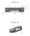
- FIG. 8 is a diagram showing the stereo camera device viewed from a direction E in FIG. 5 .
- FIG. 9 is a diagram showing a cross section of the stereo camera device between A-A in FIG. 8 .
- FIG. 1 to FIG. 9 An example of a stereo camera device according to the present invention will be described using FIG. 1 to FIG. 9 .
- FIG. 5 is a diagram showing an overview of the stereo camera device according to the present invention.
- FIG. 1 shows the internal structure.
- the diagram shows two image pickup substrates 1 (a first image pickup substrate and a second image pickup substrate), and two main substrates 2 (a first main substrate and a second main substrate).
- FIG. 2 shows a diagram viewed from a direction A in FIG. 1 ;
- FIG. 3 shows a diagram viewed from a direction B;
- FIG. 4 shows a diagram viewed from a direction C;
- FIG. 7 shows a diagram viewed from a direction D.
- FIG. 8 shows a diagram viewed from a direction E in FIG. 5 ; and
- FIG. 9 shows a cross-sectional diagram between A-A in FIG. 8 .
- FIG. 7 is also a cross-sectional diagram between B-B in FIG. 8 .
- the stereo camera device has a first image pickup unit 50 (left image pickup unit), a second image pickup unit 51 (right image pickup unit), and a case 5 as a housing in which the first image pickup unit 50 is provided at one end while the second image pickup unit 51 is provided at the other end.
- a parallax is calculated and a distance image is generated.
- an object in front of the vehicle is recognized.
- it is possible to improve recognition accuracy by arranging the elements such that the optical axis of the first image pickup unit 50 and the optical axis of the second image pickup unit 51 are parallel with each other.
- two image pickup substrates 1 (a first image pickup substrate (left image pickup substrate) and a second image pickup substrate (right image pickup substrate)), having two image pickup devices 3 (a first image pickup device (left image pickup device) and a second image pickup device (right image pickup device)) and communication connection units 4 (a first communication connection unit and a second communication connection unit) to output images captured with the image pickup devices 3 to the outside of the device, are provided in the case 5 .
- the two image pickup substrates 1 are provided symmetrically with respect to the center of the case as a housing.
- the communication connection unit 4 is provided in parallel with the left or right of the image pickup device 3 , that is, it is provided in parallel with a lengthwise direction of the case 5 as a housing.
- a main connector 12 (first connection unit) and a main connector 13 (second connection unit) as connection units for connection to two main substrates 2 (a first main substrate (power source substrate) and a second main substrate (signal processing substrate)) are provided between the two image pickup substrates 1 .
- the two main substrates 2 are overlaid in a thickness direction of the stereo camera device.
- the thickness is set as a margin of the image pickup device 3 and the image pickup substrate 1 and the case 5 , however, ideally, it is possible to reduce the thickness to the thickness of the image pickup device 3 .
- FIG. 4 is a diagram viewed from a direction C in FIG. 1 .
- lenses 6 are provided in front of (in an image pickup direction) the image pickup devices 3 , and the two main substrates 2 are overlaid therebetween.
- a power source unit 7 in the main substrates 2 , a power source unit 7 , a video processing unit 8 , and a recognition processing unit 9 are provided on one main substrate. It is possible to realize improved noise reduction by separating the substrates as a power source system and a signal processing system by providing the power source unit 7 on the first main substrate, while providing the video processing unit 8 and the recognition processing unit 9 on the second main substrate. Further, the surface of the first main substrate where the power source unit 7 is provided and the surface of the second main substrate where the video processing unit 8 and the recognition processing unit 9 are provided are arranged to be opposite to each other.
- the flow of signals will be described using FIG. 4 .
- the external information is captured through the lenses 6 as captured images into the image pickup devices 3 , and the captured image signals are transmitted via the communication connection units 4 to the main substrates 2 .
- the main substrates 2 have the power source unit 7 , the video processing unit 8 , and the recognition processing unit 9 .
- the image signals from the image pickup substrates 1 are first subjected to optical correction with the video processing unit 8 . Further, stereo matching processing is performed to obtain three dimensional information (hereinafter, a parallax image). Extraction of information necessary for the recognition processing unit 9 is performed using these corrected images and the parallax image, and a recognition object is recognized.
- the two image pickup devices 3 are provided outside the image pickup substrates 1 with respect to the position of center of gravity of the stereo camera device, or the center of the case 5 as a housing, and the communication connection units 4 are provided inside the image pickup substrates 1 , i.e., symmetrically provided with respect to the position of center of gravity. Accordingly, the distance between the two image pickup devices 3 , i.e., the length of the base length is the longest in the case 5 , and the parallax value calculated in the stereo camera device is a great value. It is possible to ensure the performance while realizing thickness reduction.
- the two image pickup substrates 1 may be point-symmetrically provided.
- it is not necessary to manufacture two types of image pickup substrates 1 it is advantageous in the point of mass production management.
- the captured images are laterally inverted as shown in FIG. 6 since the image pickup substrates are point-symmetrically provided.
- any one of the left and right image signals is rotated at 1800 so as to ensure the performance. The rotating processing is performed with any one of the image pickup devices 3 , the video processing unit 8 and the recognition processing unit 9 .
- the scan directions and reading start pixels of the left and right image pickup devices 3 are different as shown in FIG. 2 .
- the scan direction of the first image pickup device (left image pickup device) is rightward, while the scan direction of the second image pickup device (right image pickup device) is leftward. It is not possible to extract corresponding points in the left and right images due to the same problem as described above. Accordingly, it is possible to ensure the performance by setting the scan directions and the reading start pixels of the left and right image pickup devices 3 to the same position.
- the arrangement of the main substrates 2 will be described. As shown in FIGS. 2 to 4 , it is possible to realize thickness reduction by arranging the power source substrate and the signal processing substrate as the main substrates 2 in parallel in the thickness direction of the case 5 between the two image pickup substrates 1 .
- the structure has excellence in stabled relative positional relation between the left and right image pickup devices 3 , since on the both sides of any of the above-described image pickup devices 3 , thermal expansion of the left and right image pickup substrates 1 occurs from a low temperature to a high temperature as vehicle environment, mainly in the image pickup devices 3 , by fixing the image pickup substrate 1 to a fixing tool 11 with a screw A 15 .
- the screw A 15 is described as first fixing means, however, the fixing means is not selected.
- the fixing position is on horizontal both sides of the image pickup device 3 , however, it may be on vertical both sides. Note that it is possible to suppress degradation of the accuracy of the parallax image by using the same fixing means as left and right fixing means, and further, setting the fixing position symmetrically in the left and right image pickup substrates 1 .
- the structure has excellence in ensuring the performance.
- the image pickup substrate 1 is fixed to the fixing tool 11 by fixing the inner part of the image pickup substrate 1 with a screw B 16 as second fixing means, however, the fixing means is not selected. Further, regarding the fixing force of the screw B 16 (second fixing means), since fixing is performed with the screw B 16 with a smaller force than the fixing force of the screw A 15 (first fixing means) on the both sides of the image pickup device 3 , shift of the center of the image pickup substrate 1 from the center of the image pickup device 3 due to thermal expansion is further prevented. Accordingly, the structure has excellence in ensuring the performance.
- the fixing tool 11 in FIG. 4 may be a metal plate.
- the image pickup substrate 1 has a slim shape.
- the substrate is fixed to the metal plate, to improve vibration proof property. Accordingly, the structure has excellence in ensuring the reliability while realizing thickness reduction.
- the number of the main substrates 2 is two or more, and provided with at least one connector as a connection unit from each substrate.
- One main substrate 2 has the main connector 12 as the power-source related first connection unit, and the other main substrate 2 has the main connector 13 as the video-related second connection unit.
- the noise is large
- the video-related connection unit in which the large amount of signals from the image pickup devices 3 are communicated at a high speed, is week to noise. Accordingly, it is possible to ensure the performance by means of separate mounting.
- the structure has excellence in ensuring reliability while realizing thickness reduction by providing the main connector 12 and the main connector 13 in a nested form.
- the structure has excellence in realizing thickness reduction with respect to the distance from the window upon mounting in a vehicle by providing the main substrates 2 in approximately parallel with a vehicle window 14 .
- the present embodiment having the two main substrates 2 , it is possible to realize thinning by providing the two main substrates 2 in approximately parallel with the vehicle window 14 . Since not one main substrate 2 but two main substrates 2 are overlaid in the thickness direction, it is possible to reduce the length in the lengthwise direction of the stereo camera device in comparison with a case where one main substrate 2 is used.
- the lens 6 is set, not in parallel with the vehicle window 14 , but in approximately parallel with the road surface so as to be directed to a vehicle frontward direction.
Landscapes
- Engineering & Computer Science (AREA)
- Multimedia (AREA)
- Signal Processing (AREA)
- Physics & Mathematics (AREA)
- General Physics & Mathematics (AREA)
- Studio Devices (AREA)
- Measurement Of Optical Distance (AREA)
- Testing, Inspecting, Measuring Of Stereoscopic Televisions And Televisions (AREA)
- Stereoscopic And Panoramic Photography (AREA)
- Cameras In General (AREA)
Applications Claiming Priority (3)
| Application Number | Priority Date | Filing Date | Title |
|---|---|---|---|
| JP2012-213387 | 2012-09-27 | ||
| JP2012213387A JP5961506B2 (ja) | 2012-09-27 | 2012-09-27 | ステレオカメラ装置 |
| PCT/JP2013/070270 WO2014050282A1 (ja) | 2012-09-27 | 2013-07-26 | ステレオカメラ装置 |
Publications (2)
| Publication Number | Publication Date |
|---|---|
| US20150215606A1 US20150215606A1 (en) | 2015-07-30 |
| US9912935B2 true US9912935B2 (en) | 2018-03-06 |
Family
ID=50387696
Family Applications (1)
| Application Number | Title | Priority Date | Filing Date |
|---|---|---|---|
| US14/420,382 Expired - Fee Related US9912935B2 (en) | 2012-09-27 | 2013-07-26 | Stereo camera device |
Country Status (4)
| Country | Link |
|---|---|
| US (1) | US9912935B2 (ja) |
| JP (1) | JP5961506B2 (ja) |
| DE (1) | DE112013003554B4 (ja) |
| WO (1) | WO2014050282A1 (ja) |
Cited By (1)
| Publication number | Priority date | Publication date | Assignee | Title |
|---|---|---|---|---|
| US20170341598A1 (en) * | 2014-12-24 | 2017-11-30 | Toyota Jidosha Kabushiki Kaisha | Imaging device |
Families Citing this family (10)
| Publication number | Priority date | Publication date | Assignee | Title |
|---|---|---|---|---|
| JP2016014564A (ja) * | 2014-07-01 | 2016-01-28 | 株式会社リコー | 撮像ユニット |
| JP6897750B2 (ja) * | 2014-07-01 | 2021-07-07 | 株式会社リコー | 撮像ユニット |
| JP6220754B2 (ja) * | 2014-08-26 | 2017-10-25 | 日立オートモティブシステムズ株式会社 | 車載用カメラ |
| WO2016170911A1 (ja) * | 2015-04-24 | 2016-10-27 | 日立オートモティブシステムズ株式会社 | 撮像装置 |
| KR102502451B1 (ko) | 2016-01-07 | 2023-02-22 | 삼성전자주식회사 | 깊이 추정 방법 및 장치, 및 거리 추정기 학습 방법 및 장치 |
| JP7020844B2 (ja) * | 2017-09-29 | 2022-02-16 | 株式会社デンソー | 車載カメラ装置 |
| DE102018218992B4 (de) * | 2017-11-10 | 2023-02-16 | Denso Corporation | Kameramodul |
| NO20201379A1 (en) | 2018-06-12 | 2020-12-16 | Baker Hughes Holdings Llc | Gas ratio volumetrics for reservoir navigation |
| JP7154120B2 (ja) * | 2018-12-11 | 2022-10-17 | 日立Astemo株式会社 | ステレオカメラ装置 |
| JP2025167780A (ja) * | 2024-04-26 | 2025-11-07 | ミツミ電機株式会社 | 駆動装置、カメラモジュールおよびカメラ搭載装置 |
Citations (9)
| Publication number | Priority date | Publication date | Assignee | Title |
|---|---|---|---|---|
| JPH11237684A (ja) | 1998-02-20 | 1999-08-31 | Fuji Heavy Ind Ltd | ステレオカメラ |
| JP2006033346A (ja) | 2004-07-15 | 2006-02-02 | Mitsubishi Electric Corp | 着脱型撮像装置 |
| JP2006101154A (ja) | 2004-09-29 | 2006-04-13 | Canon Inc | 撮像装置 |
| US20070296846A1 (en) * | 2006-06-06 | 2007-12-27 | Barman Roderick A | High accuracy stereo camera |
| US20080001727A1 (en) * | 2004-11-15 | 2008-01-03 | Hitachi, Ltd. | Stereo Camera |
| JP2008306350A (ja) | 2007-06-06 | 2008-12-18 | Hitachi Maxell Ltd | カメラモジュール及び撮像装置 |
| WO2011068139A1 (ja) | 2009-12-01 | 2011-06-09 | Inaba Minoru | 立体映像撮像装置 |
| JP2012173737A (ja) | 2011-02-17 | 2012-09-10 | Samsung Electro-Mechanics Co Ltd | ステレオカメラ及びその製造方法 |
| US9204041B1 (en) * | 2012-07-03 | 2015-12-01 | Gopro, Inc. | Rolling shutter synchronization |
Family Cites Families (7)
| Publication number | Priority date | Publication date | Assignee | Title |
|---|---|---|---|---|
| JP3353408B2 (ja) | 1993-08-02 | 2002-12-03 | 三菱電機株式会社 | 車載用撮影装置 |
| JP3631270B2 (ja) | 1994-10-13 | 2005-03-23 | オリンパス株式会社 | 電子機器 |
| JP3919321B2 (ja) * | 1998-03-10 | 2007-05-23 | キヤノン株式会社 | 撮像装置 |
| JP3894364B2 (ja) | 2002-02-04 | 2007-03-22 | 富士フイルム株式会社 | カメラ |
| JP4241013B2 (ja) * | 2002-11-26 | 2009-03-18 | 富士ゼロックス株式会社 | 画像形成装置並びにこれに用いられるフレーム構造及びその製造方法 |
| JP3684365B2 (ja) * | 2003-02-21 | 2005-08-17 | フジノン株式会社 | 立体電子内視鏡用撮像装置 |
| KR101149021B1 (ko) | 2010-10-08 | 2012-05-24 | 엘지이노텍 주식회사 | 3차원 촬상장치와 그 제조방법 |
-
2012
- 2012-09-27 JP JP2012213387A patent/JP5961506B2/ja not_active Expired - Fee Related
-
2013
- 2013-07-26 DE DE112013003554.5T patent/DE112013003554B4/de not_active Expired - Fee Related
- 2013-07-26 WO PCT/JP2013/070270 patent/WO2014050282A1/ja not_active Ceased
- 2013-07-26 US US14/420,382 patent/US9912935B2/en not_active Expired - Fee Related
Patent Citations (11)
| Publication number | Priority date | Publication date | Assignee | Title |
|---|---|---|---|---|
| JPH11237684A (ja) | 1998-02-20 | 1999-08-31 | Fuji Heavy Ind Ltd | ステレオカメラ |
| JP2006033346A (ja) | 2004-07-15 | 2006-02-02 | Mitsubishi Electric Corp | 着脱型撮像装置 |
| JP2006101154A (ja) | 2004-09-29 | 2006-04-13 | Canon Inc | 撮像装置 |
| US20080001727A1 (en) * | 2004-11-15 | 2008-01-03 | Hitachi, Ltd. | Stereo Camera |
| JP2011123078A (ja) | 2004-11-15 | 2011-06-23 | Hitachi Automotive Systems Ltd | ステレオカメラ |
| US20070296846A1 (en) * | 2006-06-06 | 2007-12-27 | Barman Roderick A | High accuracy stereo camera |
| JP2008306350A (ja) | 2007-06-06 | 2008-12-18 | Hitachi Maxell Ltd | カメラモジュール及び撮像装置 |
| US20120257024A1 (en) | 2009-01-12 | 2012-10-11 | Minoru Inaba | Stereoscopic imaging device |
| WO2011068139A1 (ja) | 2009-12-01 | 2011-06-09 | Inaba Minoru | 立体映像撮像装置 |
| JP2012173737A (ja) | 2011-02-17 | 2012-09-10 | Samsung Electro-Mechanics Co Ltd | ステレオカメラ及びその製造方法 |
| US9204041B1 (en) * | 2012-07-03 | 2015-12-01 | Gopro, Inc. | Rolling shutter synchronization |
Non-Patent Citations (1)
| Title |
|---|
| International Search Report (PCT/ISA/210), dated Sep. 10, 2013 with English-language translation (Four (4) pages). |
Cited By (2)
| Publication number | Priority date | Publication date | Assignee | Title |
|---|---|---|---|---|
| US20170341598A1 (en) * | 2014-12-24 | 2017-11-30 | Toyota Jidosha Kabushiki Kaisha | Imaging device |
| US10150427B2 (en) * | 2014-12-24 | 2018-12-11 | Kabushiki Kaisha Tokai-Rika-Denki-Seisakusho | Imaging unit support structure |
Also Published As
| Publication number | Publication date |
|---|---|
| JP5961506B2 (ja) | 2016-08-02 |
| DE112013003554B4 (de) | 2023-01-12 |
| US20150215606A1 (en) | 2015-07-30 |
| JP2014066948A (ja) | 2014-04-17 |
| WO2014050282A1 (ja) | 2014-04-03 |
| DE112013003554T5 (de) | 2015-04-09 |
Similar Documents
| Publication | Publication Date | Title |
|---|---|---|
| US20150215606A1 (en) | Stereo Camera Device | |
| US10298821B2 (en) | Lens mounting mechanism, lens mounting method, and image pickup device | |
| US10291902B2 (en) | Three-dimensional camera assembly, terminal apparatus and ranging method | |
| CN112840268B (zh) | 相机致动器和包括相机致动器的相机模块 | |
| US11225204B2 (en) | On-vehicle image processing device | |
| EP2418860A1 (en) | Image sensor for generating stereoscopic images | |
| US11102384B2 (en) | Camera substrate assembly, camera module, and terminal device | |
| US20150029313A1 (en) | Method for aligning two image recording elements of a stereo camera system | |
| US10992920B2 (en) | Stereo image processing device | |
| US12069226B2 (en) | Imaging device | |
| EP3288250B1 (en) | Imaging device | |
| CN110214376B (zh) | 半导体装置及电子设备 | |
| TWI514065B (zh) | 360 degree road traffic recorder | |
| JP2014065393A (ja) | ステレオカメラ装置 | |
| US10244154B2 (en) | Imaging collecting system, image collecting processing system and image collecting processing method | |
| JP5713125B2 (ja) | 撮像装置 | |
| KR20140037656A (ko) | 카메라 모듈 | |
| WO2024202957A1 (ja) | 複眼カメラモジュール及び電子機器 | |
| US9591287B2 (en) | Lens module applied to camera | |
| JP2016027335A (ja) | 車載画像処理装置 | |
| KR101983014B1 (ko) | 카메라 모듈 | |
| CN115380233A (zh) | 拍摄装置 | |
| JP2019060874A (ja) | 車用ステレオビジョンシステム | |
| JP2016031308A (ja) | 撮像装置、撮像システム、及び、移動体 |
Legal Events
| Date | Code | Title | Description |
|---|---|---|---|
| AS | Assignment |
Owner name: HITACHI AUTOMOTIVE SYSTEMS, LTD., JAPAN Free format text: ASSIGNMENT OF ASSIGNORS INTEREST;ASSIGNORS:SASADA, YOSHIYUKI;YAMAZAKI, SATOSHI;OHSUMI, KEN;SIGNING DATES FROM 20141211 TO 20141212;REEL/FRAME:034927/0089 |
|
| STCF | Information on status: patent grant |
Free format text: PATENTED CASE |
|
| AS | Assignment |
Owner name: HITACHI ASTEMO, LTD., JAPAN Free format text: CHANGE OF NAME;ASSIGNOR:HITACHI AUTOMOTIVE SYSTEMS, LTD.;REEL/FRAME:056299/0447 Effective date: 20210101 |
|
| MAFP | Maintenance fee payment |
Free format text: PAYMENT OF MAINTENANCE FEE, 4TH YEAR, LARGE ENTITY (ORIGINAL EVENT CODE: M1551); ENTITY STATUS OF PATENT OWNER: LARGE ENTITY Year of fee payment: 4 |
|
| FEPP | Fee payment procedure |
Free format text: MAINTENANCE FEE REMINDER MAILED (ORIGINAL EVENT CODE: REM.); ENTITY STATUS OF PATENT OWNER: LARGE ENTITY |
|
| LAPS | Lapse for failure to pay maintenance fees |
Free format text: PATENT EXPIRED FOR FAILURE TO PAY MAINTENANCE FEES (ORIGINAL EVENT CODE: EXP.); ENTITY STATUS OF PATENT OWNER: LARGE ENTITY |
|
| STCH | Information on status: patent discontinuation |
Free format text: PATENT EXPIRED DUE TO NONPAYMENT OF MAINTENANCE FEES UNDER 37 CFR 1.362 |
|
| FP | Lapsed due to failure to pay maintenance fee |
Effective date: 20260306 |