US9808898B2 - Sealing system for a tool holder - Google Patents
Sealing system for a tool holder Download PDFInfo
- Publication number
- US9808898B2 US9808898B2 US14/442,497 US201314442497A US9808898B2 US 9808898 B2 US9808898 B2 US 9808898B2 US 201314442497 A US201314442497 A US 201314442497A US 9808898 B2 US9808898 B2 US 9808898B2
- Authority
- US
- United States
- Prior art keywords
- tool
- seal
- adapter
- sealing system
- diameter
- Prior art date
- Legal status (The legal status is an assumption and is not a legal conclusion. Google has not performed a legal analysis and makes no representation as to the accuracy of the status listed.)
- Expired - Fee Related, expires
Links
Images


Classifications
-
- B—PERFORMING OPERATIONS; TRANSPORTING
- B23—MACHINE TOOLS; METAL-WORKING NOT OTHERWISE PROVIDED FOR
- B23B—TURNING; BORING
- B23B31/00—Chucks; Expansion mandrels; Adaptations thereof for remote control
- B23B31/02—Chucks
- B23B31/10—Chucks characterised by the retaining or gripping devices or their immediate operating means
- B23B31/12—Chucks with simultaneously-acting jaws, whether or not also individually adjustable
- B23B31/20—Longitudinally-split sleeves, e.g. collet chucks
- B23B31/201—Characterized by features relating primarily to remote control of the gripping means
- B23B31/2012—Threaded cam actuator
-
- B—PERFORMING OPERATIONS; TRANSPORTING
- B23—MACHINE TOOLS; METAL-WORKING NOT OTHERWISE PROVIDED FOR
- B23Q—DETAILS, COMPONENTS, OR ACCESSORIES FOR MACHINE TOOLS, e.g. ARRANGEMENTS FOR COPYING OR CONTROLLING; MACHINE TOOLS IN GENERAL CHARACTERISED BY THE CONSTRUCTION OF PARTICULAR DETAILS OR COMPONENTS; COMBINATIONS OR ASSOCIATIONS OF METAL-WORKING MACHINES, NOT DIRECTED TO A PARTICULAR RESULT
- B23Q11/00—Accessories fitted to machine tools for keeping tools or parts of the machine in good working condition or for cooling work; Safety devices specially combined with or arranged in, or specially adapted for use in connection with, machine tools
- B23Q11/10—Arrangements for cooling or lubricating tools or work
- B23Q11/1015—Arrangements for cooling or lubricating tools or work by supplying a cutting liquid through the spindle
- B23Q11/1023—Tool holders, or tools in general specially adapted for receiving the cutting liquid from the spindle
-
- B—PERFORMING OPERATIONS; TRANSPORTING
- B23—MACHINE TOOLS; METAL-WORKING NOT OTHERWISE PROVIDED FOR
- B23B—TURNING; BORING
- B23B31/00—Chucks; Expansion mandrels; Adaptations thereof for remote control
- B23B31/02—Chucks
-
- B—PERFORMING OPERATIONS; TRANSPORTING
- B23—MACHINE TOOLS; METAL-WORKING NOT OTHERWISE PROVIDED FOR
- B23B—TURNING; BORING
- B23B31/00—Chucks; Expansion mandrels; Adaptations thereof for remote control
- B23B31/02—Chucks
- B23B31/10—Chucks characterised by the retaining or gripping devices or their immediate operating means
- B23B31/12—Chucks with simultaneously-acting jaws, whether or not also individually adjustable
- B23B31/20—Longitudinally-split sleeves, e.g. collet chucks
-
- B—PERFORMING OPERATIONS; TRANSPORTING
- B23—MACHINE TOOLS; METAL-WORKING NOT OTHERWISE PROVIDED FOR
- B23Q—DETAILS, COMPONENTS, OR ACCESSORIES FOR MACHINE TOOLS, e.g. ARRANGEMENTS FOR COPYING OR CONTROLLING; MACHINE TOOLS IN GENERAL CHARACTERISED BY THE CONSTRUCTION OF PARTICULAR DETAILS OR COMPONENTS; COMBINATIONS OR ASSOCIATIONS OF METAL-WORKING MACHINES, NOT DIRECTED TO A PARTICULAR RESULT
- B23Q11/00—Accessories fitted to machine tools for keeping tools or parts of the machine in good working condition or for cooling work; Safety devices specially combined with or arranged in, or specially adapted for use in connection with, machine tools
- B23Q11/10—Arrangements for cooling or lubricating tools or work
- B23Q11/1015—Arrangements for cooling or lubricating tools or work by supplying a cutting liquid through the spindle
- B23Q11/103—Rotary joints specially adapted for feeding the cutting liquid to the spindle
-
- B—PERFORMING OPERATIONS; TRANSPORTING
- B23—MACHINE TOOLS; METAL-WORKING NOT OTHERWISE PROVIDED FOR
- B23B—TURNING; BORING
- B23B2231/00—Details of chucks, toolholder shanks or tool shanks
- B23B2231/24—Cooling or lubrication means
-
- B—PERFORMING OPERATIONS; TRANSPORTING
- B23—MACHINE TOOLS; METAL-WORKING NOT OTHERWISE PROVIDED FOR
- B23B—TURNING; BORING
- B23B2250/00—Compensating adverse effects during turning, boring or drilling
- B23B2250/12—Cooling and lubrication
-
- Y—GENERAL TAGGING OF NEW TECHNOLOGICAL DEVELOPMENTS; GENERAL TAGGING OF CROSS-SECTIONAL TECHNOLOGIES SPANNING OVER SEVERAL SECTIONS OF THE IPC; TECHNICAL SUBJECTS COVERED BY FORMER USPC CROSS-REFERENCE ART COLLECTIONS [XRACs] AND DIGESTS
- Y10—TECHNICAL SUBJECTS COVERED BY FORMER USPC
- Y10T—TECHNICAL SUBJECTS COVERED BY FORMER US CLASSIFICATION
- Y10T279/00—Chucks or sockets
- Y10T279/17—Socket type
- Y10T279/17111—Fluid-conduit drill holding
-
- Y—GENERAL TAGGING OF NEW TECHNOLOGICAL DEVELOPMENTS; GENERAL TAGGING OF CROSS-SECTIONAL TECHNOLOGIES SPANNING OVER SEVERAL SECTIONS OF THE IPC; TECHNICAL SUBJECTS COVERED BY FORMER USPC CROSS-REFERENCE ART COLLECTIONS [XRACs] AND DIGESTS
- Y10—TECHNICAL SUBJECTS COVERED BY FORMER USPC
- Y10T—TECHNICAL SUBJECTS COVERED BY FORMER US CLASSIFICATION
- Y10T408/00—Cutting by use of rotating axially moving tool
- Y10T408/44—Cutting by use of rotating axially moving tool with means to apply transient, fluent medium to work or product
- Y10T408/45—Cutting by use of rotating axially moving tool with means to apply transient, fluent medium to work or product including Tool with duct
-
- Y—GENERAL TAGGING OF NEW TECHNOLOGICAL DEVELOPMENTS; GENERAL TAGGING OF CROSS-SECTIONAL TECHNOLOGIES SPANNING OVER SEVERAL SECTIONS OF THE IPC; TECHNICAL SUBJECTS COVERED BY FORMER USPC CROSS-REFERENCE ART COLLECTIONS [XRACs] AND DIGESTS
- Y10—TECHNICAL SUBJECTS COVERED BY FORMER USPC
- Y10T—TECHNICAL SUBJECTS COVERED BY FORMER US CLASSIFICATION
- Y10T409/00—Gear cutting, milling, or planing
- Y10T409/30—Milling
- Y10T409/303976—Milling with means to control temperature or lubricate
- Y10T409/304032—Cutter or work
Definitions
- the present invention relates to fluid-assisted machining.
- a fluid such as a lubricant, notably a straight oil, a soluble oil, an oil/water mixture or a gas, to the tip of the tool.
- a sealing system at tool-holder level may be employed. This system then needs to perform both, on the one hand, the function of conveying the fluid to a manifold communicating with one or more internal passages of the tool that are able to convey it as far as the end thereof, to the region of the cutting zone in particular, and, on the other hand, the function of guiding and of transmitting the torque needed for rotating the tool.
- Seals are used and come into contact with the manifold in order to seal the circulation of fluid from a fluid inlet.
- the sizing of the tool holder to allow it to transmit the torque dictates the use of a manifold of relatively large diameter and the seals providing sealing come into contact with a rubbing surface, defined by the manifold, which is of a relatively large diameter.
- peripheral rubbing speed of the seals is therefore high and the direct consequence of this is a limit on the maximum rotational frequency of the tool, thereby preventing certain operating domains.
- This limit usually lies at around about 5000 revolutions per minute and becomes all the more problematical when the drilling is a small-diameter drilling, because rotational frequency is inversely proportional to the diameter of the tool.
- U.S. Pat. No. 7,147,410 discloses a tool holder in which the tool is engaged in a clamping ring against which two seals press in order to define a space in which a fluid coolant flows as far as the tool.
- a sealing system for a tool holder of a cutting fluid-assisted machine tool comprising:
- the invention can be applied equally to vibrational drilling methods and to conventional drilling methods and is quite particularly suitable for the fleets of machine tools that are not equipped with rotary seals and that work on a limited number of drilling diameters, entailing few, if any, changes of tool holder.
- the sealing may be achieved by virtue of the invention on rubbing surfaces the diameter of which is close to that of the tool, or even on the tool itself, thereby making it possible to reduce the rubbing speed and allow a higher rotational frequency.
- the two seals press against the tool or against the adapter according to the first variant a), which is preferred but may dictate the use of special-purpose tools.
- One of the seals presses against the tool and the other against a surface of the tool holder, according to the second variant b), which is easier to implement on the majority of the tools in existence in the marketplace.
- the surface against which the second seal presses in variant b) is defined by a wall of the tool holder, which wall is preferably defined by an adapter ring, which may preferably come into contact with a tool clamping means, notably an expanding collet.
- the adapter ring may be at least partially engaged inside a collet nut. Said wall is in contact on one side with the rubbing surface of the seal, and on the opposite side extends away from the tool to allow the fluid to circulate between the tool of the tool holder as far as said internal passage in the tool.
- This wall is preferably as thin as possible and as close as possible to the tool.
- the adapter ring may be replaced by another, adapted to the new diameter of tool.
- the surface against which the second seal presses in variant b) is defined by an adapter sleeve which fits around the tool and comes into contact with the expanding collet.
- the adapter sleeve is preferably deformable. As the collet is tightened, the adapter sleeve can deform, preferably elastically, and come into contact with the tool to grip it, transmitting the torque of the collet to it and holding it in place and centered. When the collet is loosened, the adapter sleeve preferably reverts to its previous shape and releases the tool.
- the adapter sleeve may comprise at least 3 longitudinal grooves, notably depending on the diameter of the tool. The larger the external diameter of the tool, the higher may be the number of grooves and the more the cutting fluid may circulate.
- the adapter sleeve may be replaced by another, adapted to the new diameter of tool.
- the adapter sleeve may comprise an annular groove intended to accept a snap ring (circlip) arranged between the collet and a seal-bearing ring.
- the snap ring allows the adapter sleeve to be immobilized axially and makes it possible to limit the depth to which it penetrates the tool holder.
- the sealing of the internal end of the sleeve may be performed by a seal arranged between an end plug and the inside surface of the sleeve.
- the seal may be an O-ring seal housed in an annular groove of the sleeve.
- the end plug may be fitted by sliding it into the adapter sleeve from the opposite end from the seal and it is held against the seal by the pressure of the cutting fluid in the adapter sleeve in order to seal the adapter sleeve closed.
- the end plug may comprise an annular groove of substantially quadrant shape, notably having an angular extent about the center of the section of slightly more than 90°, preferably of between 90° and 120°, in order to accept the O-ring seal.
- the fluid pressure in the adapter sleeve is preferably comprised between 1 bar and 10 bar, better between 1 bar and 7 bar.
- the seals are advantageously borne by the seal-bearing ring of the sealing system, which ring is adapted to the diameter of the tool or of the adapter bearing the tool, arranged in contact with a stator acting as a coupling for a fluid inlet, in pivoting connection with the collet nut via a rolling bearing.
- this seal-bearing ring may be replaced by a new ring adapted to the new diameter of the tool.
- the sealing system may be offered with components which are the same for all diameters of tool, notably the collet nut and certain parts of the stator, and with others which are changed according to the diameter of the tool, notably the seal-bearing ring, the seals, the adapter ring or the adapter sleeve, or even the collet (if the user does not already have same).
- All the components that are changed according to the diameter of the tool may thus define ranges of adapter rings or of adapter sleeves, of seal-bearing rings and of seals adapted to different diameters of tool, which are offered to the user together with the other components of the sealing system, which may themselves be invariable.
- Another subject of the invention in another aspect thereof, is a range of sealing systems or of components of a sealing system, which are adapted to respective tools of different diameters, including a tool or adapter of diameter D 1 and a tool or adapter of diameter D 2 greater than D 1 .
- Each sealing system also comprises a second seal likewise contributing to delimiting the space for the circulation of the fluid, the second seal of the first sealing system being intended to collaborate with the tool or adapter of diameter D 1 , the second seal of the first sealing system being of an inside diameter less than the inside diameter of the second seal of the second sealing system, intended to collaborate with the tool or adapter of diameter D 2 .
- the user can therefore be offered, in the same package, two sealing systems adapted to different diameters of tool, or, better, a first sealing system and the components that allow this first sealing system to be modified by reusing some of its components and supplementing them with components specific to the other diameters of tool or of adapter.
- the package may thus contain the stator of the sealing system and the collet nut, and ranges of seals, seal-bearing rings and of adapter rings or adapter seals adapted to the various diameters of tool.
- Yet another subject of the invention is a range of at least a first and a second sealing system, or a set of at least a first sealing system and a range of components that allow this first sealing system to be modified to form a second sealing system by reusing components of the first sealing system, the two sealing systems being intended for one and the same tool holder of a cutting fluid-assisted machine tool, adapted to different diameters D 1 and D 2 of tool or adapter, and to different diameters D 3 and D 4 of adapter rings or adapter sleeves mounted on the tools or adapters where D 2 is greater than D 1 , and D 4 greater than D 3 , each sealing system comprising at least a first seal contributing to delimiting a space for the circulation of the fluid toward at least one internal passage of the tool, the seal being interposed between surfaces to which a relative rotational movement is imparted, as the tool rotates, the first seal of the first sealing system being intended to press against the adapter ring or the adapter sleeve of diameter D 3 , and the first seal of the
- Yet another subject of the invention is a machining method, comprising the steps involving:
- the choice of components may be restricted, aside from the choice of an adapted clamping means such as an expanding collet, to the choice of a seal-bearing ring (with the seals) that is adapted to the diameter of the tool or of the adapter bearing the tool, notably when the two seals each come into contact with the tool or with an adapter to which the tool is fixed, or to the choice of a seal-bearing ring (with the seals) and of an adapter ring or an adapter sleeve, when just one of the seals presses directly against the tool and the other presses against the adapter ring or the adapter sleeve.
- an adapted clamping means such as an expanding collet
- FIG. 1 is a simplified diagram of one variant of the invention, given by way of introduction,
- FIGS. 2A, 3A, 4A, 5A, 6A are end-on views of tool holders according to the invention, with adapted tools and sealing systems,
- FIGS. 2B, 3B, 4B, 5B, 6B are views in longitudinal section, on IIB-IIB, IIIB-IIIB, IVB-IVB, VB-VB, VIB-VIB of FIGS. 2A, 3A, 4A, 5A, 6A , respectively, and
- FIGS. 2C, 3C, 4C, 5C, 6C are side views of the tool holders of FIGS. 2A, 3A, 4A, 5A, 6A , respectively, and
- FIGS. 7 and 8 are longitudinal sections of variants of tool-holder according to the invention.
- the tool has been depicted schematically in the figures.
- the invention is not restricted to one particular tool, and this tool may be something other than a drill bit.
- FIG. 1 is a simplified depiction of a tool-holder 10 produced in accordance with the invention, notably in accordance with variant b) defined above, in which one of the seals presses against a surface of the tool holder and the other presses directly against the tool.
- the tool holder 10 takes a tool 20 , depicted schematically, comprising an internal passage 21 that allows fluid to be conveyed from an inlet 22 , situated for example as illustrated at the proximal (shank) end of the tool, toward one or more outlets 23 situated near a cutting edge 24 of the tool.
- This fluid is typically a lubricant.
- the tool is held by the tool holder in such a way as to allow the transmission of torque and circulation of fluid to the inlet 22 and comprises a structure which defines a circulation space 41 .
- the latter is delimited notably by two seals 50 and 60 which press against respective surfaces 51 and 61 formed respectively on the structure and on the tool 20 .
- the seals 50 and 60 are borne by a stator 70 , depicted schematically.
- the surface 51 against which the seal 50 presses is of diameter D jmax and that 61 of the tool 20 on which the seal 60 presses is of diameter Do.
- Do and D jmax satisfy the relationship 0.3 ⁇ Do/Dj max for Do in the range [1; 3] in mm and 0.5 ⁇ Do/Dj max for Do in the range [3; 20] in mm, where Dj max is the internal diameter of the larger of the two seals, namely the seal referenced 50 .
- the rubbing speed is thus reduced and a higher rotational frequency, notably one greater than or equal to 5000 rpm, can be tolerated.
- the tool holder is produced in such a way as to minimize D jmax while at the same time leaving a sufficient passage for the fluid to pass as far as the inlet 22 into the tool 20 .
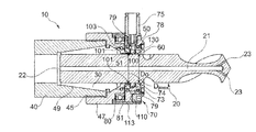
- the tool holder comprises a body 40 provided with a conical recess 49 collaborating with a collet 30 and a collet nut 47 that tightens the collet 30 is screwed onto a screw thread 45 of the body 40 .
- the body 40 rotates with the tool 20 guiding a rolling bearing 80 of which one of the rings, referenced 81 , the radially outermost one, is fixed with respect to the stator 70 .
- the tool holder comprises an adapter ring 101 having a thinned wall 100 against which the rubbing surface 51 of the seal 50 presses.
- This wall 100 extends a small distance away from the surface of the tool 20 , so as to minimize the internal diameter of the seal 50 .
- the adapter ring 101 is assembled with the collet nut 47 with the interposition of an O-ring seal 103 , in order to seal the assembly.
- the adapter ring 101 comes into contact with the end of the collet 30 , in the example being considered, and this ensures that it is completely immobilized in the tool holder.
- the seals 50 and 60 are borne by a seal-bearing ring 73 mounted on a body 78 of the stator 70 , the ring 73 defining, with the seals 50 and 60 , a chamber 74 into which the fluid from a coupling end fitting 75 is injected via orifices 130 .
- the seal-bearing ring 73 is held on the body 78 of the stator 70 with the interposition of O-ring seals 79 , in order to seal the assembly.
- Set screws 110 hold the rolling bearing 80 by collaborating with an outside ring 113 mounted on the body 78 of the stator 70 .
- the tool 20 is of a smaller diameter than in the example of FIGS. 2A to 2C , for example 16 mm instead of 20 mm.
- the collet 30 is different, being adapted to the new diameter of tool 20 .
- the body 40 is unchanged, as is the collet nut 47 .
- the adapter ring 101 is replaced by a new ring of smaller inside diameter, so as to compensate for the reduction in the diameter of the tool 20 . Replacing the adapter ring 101 means that the smallest possible clearance suited to the circulation of the fluid can be maintained between the thinned wall 100 and the surface of the tool 20 .
- the seal-bearing ring 73 is also replaced by a ring adapted to the seals that it is to hold and has bores of different diameters.
- the user has available several components adapted to different diameters of tool, such as a range of seal-bearing rings 73 (with their seals) and of adapter rings 101 which are adapted to specific diameters of tool.
- the tool holder comprises an adapter sleeve 140 against which the seal 50 presses.
- the adapter sleeve 140 fits around the tool 20 and is arranged radially between the collet 30 and the tool 20 .
- the adapter sleeve 140 extends longitudinally between the chamber 74 into which the fluid is injected by the coupling end piece 75 and the internal end of the tool holder.
- the adapter sleeve 140 is deformable and as the collet 30 is tightened, it can transmit the clamping force to the tool 20 in order to hold the latter in place.
- the adapter sleeve 140 relaxes and frees the tool 20 .
- the adapter sleeve 140 comprises, as illustrated in FIG. 7 , at least one longitudinal groove 143 , better a plurality of longitudinal grooves 143 , extending over its internal surface over its entire length.
- the longitudinal grooves 143 open out, at one end of the adapter sleeve 140 , onto the chamber 74 and, at the other end of the adapter sleeve 140 , onto a space 145 communicating with the inlet 22 of the internal passage 21 of the tool 20 .
- the longitudinal grooves 143 allow cutting fluid to circulate from the chamber 74 to the internal passage 21 of the tool in order to be fed to this tool.
- the internal end of the adapter sleeve 140 comprises a plug 148 adapted to the diameter of the tool 20 and bears an end seal 150 .
- the latter is positioned between the plug 148 and the adapter sleeve 140 and makes it possible to limit the losses of cutting fluid.
- the end seal 150 is positioned in the adapter sleeve 140 in a groove 151 of the adapter sleeve 140 .
- the plug 148 is inserted into the adapter sleeve 140 via the other end thereof so as to slide into the adapter sleeve 140 and become pressed against the end seal 150 in order to ensure sealed closure of the adapter sleeve 140 .
- the plug 148 comprises a groove 151 intended to accept the end seal 150 .
- the latter may clip into the groove 151 .
- the latter has a cross section slightly exceeding a quadrant, notably of between 90° and 120°. Because the groove 151 is open in the opposite direction to the end via which the plug is introduced into the sleeve, a greater space 149 is created behind the seal 150 between the plug 148 and the internal surface of the sleeve 140 .
- the end seal 150 restrains the plug 148 against the pressure of the cutting fluid in the adapter sleeve, comprised between 1 bar and 10 bar, better between 1 bar and 7 bar.
- the adapter sleeve 140 comprises an annular groove 153 which accepts a snap ring (circlip) 155 positioned between the collet 30 and the seal-bearing ring 73 .
- the snap ring 155 is positioned in the annular groove 153 and immobilizes the adapter sleeve 140 at a predetermined depth of penetration.
- the adapter sleeve 140 , the plug 148 , the end seal 150 and the snap ring 155 are adapted to the diameter of the tool 20 .
- FIGS. 4A to 4C is similar to that of FIGS. 3A to 3C , for another diameter of tool, which is smaller still, for example 12 mm.
- these seals press against an adapter to which the tool is fixed, as described later on.
- the latter in order to ensure the supply of fluid to the tool 20 , the latter is provided with at least one internal passage 27 opening into the fluid circulation space 74 , between the seals 50 and 60 .
- the tool 20 comprises several radial passages 24 communicating with the longitudinal internal passage 21 , which is plugged by a plug 28 at its proximal (tool shank) end.
- the adapter ring 101 of the examples of FIGS. 3A and 3B is no longer needed because the seals press directly against the tool 20 and because the fluid is no longer inlet via the proximal end thereof.
- the tool 20 is borne by an adapter 120 .
- the tool 20 has, for example, as illustrated, a shank 29 screwed into a tapping 121 of the adapter.
- the passage 21 of the tool communicates with a chamber 122 into which there open radial passages 127 of the adapter that perform the same function as the passages 27 described previously.
- the seals 50 and 60 press against the adapter 120 .
- Clamping means other than an expanding collet may be used, for example a shrink-fitted band, mechanical binding band, or radial clamping.
Landscapes
- Engineering & Computer Science (AREA)
- Mechanical Engineering (AREA)
- Auxiliary Devices For Machine Tools (AREA)
- Gripping On Spindles (AREA)
- Jigs For Machine Tools (AREA)
Applications Claiming Priority (3)
| Application Number | Priority Date | Filing Date | Title |
|---|---|---|---|
| FR1260796A FR2997878B1 (fr) | 2012-11-13 | 2012-11-13 | Systeme d'etancheite pour porte-outil |
| FR1260796 | 2012-11-13 | ||
| PCT/IB2013/060101 WO2014076641A1 (fr) | 2012-11-13 | 2013-11-13 | Systeme d'etancheite pour porte-outil |
Publications (2)
| Publication Number | Publication Date |
|---|---|
| US20160039064A1 US20160039064A1 (en) | 2016-02-11 |
| US9808898B2 true US9808898B2 (en) | 2017-11-07 |
Family
ID=47833153
Family Applications (1)
| Application Number | Title | Priority Date | Filing Date |
|---|---|---|---|
| US14/442,497 Expired - Fee Related US9808898B2 (en) | 2012-11-13 | 2013-11-13 | Sealing system for a tool holder |
Country Status (7)
| Country | Link |
|---|---|
| US (1) | US9808898B2 (https=) |
| EP (1) | EP2919943B1 (https=) |
| JP (1) | JP6487329B2 (https=) |
| CA (1) | CA2891468C (https=) |
| ES (1) | ES2761573T3 (https=) |
| FR (1) | FR2997878B1 (https=) |
| WO (1) | WO2014076641A1 (https=) |
Cited By (1)
| Publication number | Priority date | Publication date | Assignee | Title |
|---|---|---|---|---|
| US20210394285A1 (en) * | 2020-06-18 | 2021-12-23 | Ford Global Technologies, Llc | 3d printed gear cutting tools with capillaries for minimum quantity lubrication, gas or liquid |
Families Citing this family (3)
| Publication number | Priority date | Publication date | Assignee | Title |
|---|---|---|---|---|
| PL221286B1 (pl) * | 2013-05-29 | 2016-03-31 | Bomar Spółka Akcyjna | Oprawka do mocowania narzędzi tokarskich trzonkowych |
| CH709850A1 (de) * | 2014-07-07 | 2016-01-15 | Rego Fix Ag | Vorrichtung zur Zuführung von Kühl- oder Schmierflüssigkeit zu drehfesten, in Drehmaschinen eingespannten Werkzeugen. |
| JP7624793B2 (ja) | 2021-04-30 | 2025-01-31 | 株式会社ナカニシ | モータスピンドル |
Citations (13)
| Publication number | Priority date | Publication date | Assignee | Title |
|---|---|---|---|---|
| US904692A (en) * | 1907-12-28 | 1908-11-24 | Cleveland Pneumatic Tool Co | Stone-working tool. |
| US3229427A (en) * | 1963-07-29 | 1966-01-18 | Diagrit Electrometallics Ltd | Apparatus for performing a drilling operation on a workpiece |
| FR1568265A (https=) * | 1968-03-22 | 1969-05-23 | ||
| US3791660A (en) * | 1973-01-09 | 1974-02-12 | Bendix Corp | Device for gripping, driving and supplying coolant to a cutting tool having coolant passages therein |
| GB1366638A (en) | 1972-01-13 | 1974-09-11 | Tempered Tools Ltd | Drill lubrication adaptors |
| FR2295810A1 (fr) * | 1974-12-28 | 1976-07-23 | Beck August | Foret helicoidal |
| US4570952A (en) * | 1984-05-25 | 1986-02-18 | Thomas Heimbigner | Fluid collet chuck |
| US4693646A (en) * | 1986-02-18 | 1987-09-15 | Gemcor Engineering Corp. | Apparatus for lubricating a workpiece |
| EP0629462A2 (en) | 1993-06-18 | 1994-12-21 | Daishowa Seiki Co., Ltd. | Coolant feeder in a tool holder assembly |
| JPH09155614A (ja) * | 1995-12-12 | 1997-06-17 | Kanefusa Kk | シャンク付回転工具 |
| EP1541279A1 (en) | 2002-09-05 | 2005-06-15 | Kanefusa Kabushiki Kaisha | Mist feeding mechanism of rotary tool |
| US7147410B2 (en) | 2002-02-08 | 2006-12-12 | Wto Werkzeug-Einrichtungen Gmbh | Tool head for holding a tool in a machine tool |
| US20110222976A1 (en) * | 2010-03-12 | 2011-09-15 | Sugino Machine Limited | Working unit |
Family Cites Families (6)
| Publication number | Priority date | Publication date | Assignee | Title |
|---|---|---|---|---|
| JPH04111705A (ja) * | 1990-08-31 | 1992-04-13 | Toyoda Gosei Co Ltd | 内周切削工具 |
| JPH0825124B2 (ja) * | 1993-06-18 | 1996-03-13 | 大昭和精機株式会社 | 工具ホルダーにおける給油装置 |
| JP2529827Y2 (ja) * | 1993-10-27 | 1997-03-19 | ビッグアルファ株式会社 | 工具チャック用コレット |
| JPH08290346A (ja) * | 1995-02-22 | 1996-11-05 | Koyo Mach Ind Co Ltd | 遊星増速機構内蔵スピンドル装置 |
| JP4199842B2 (ja) * | 1998-01-22 | 2008-12-24 | 富士機械製造株式会社 | タレット装置およびそれに好適な開閉弁付接続装置 |
| JP2010064165A (ja) * | 2008-09-09 | 2010-03-25 | Kanzaki Kokyukoki Mfg Co Ltd | 深穴加工装置 |
-
2012
- 2012-11-13 FR FR1260796A patent/FR2997878B1/fr not_active Expired - Fee Related
-
2013
- 2013-11-13 CA CA2891468A patent/CA2891468C/fr active Active
- 2013-11-13 US US14/442,497 patent/US9808898B2/en not_active Expired - Fee Related
- 2013-11-13 EP EP13799111.3A patent/EP2919943B1/fr active Active
- 2013-11-13 WO PCT/IB2013/060101 patent/WO2014076641A1/fr not_active Ceased
- 2013-11-13 ES ES13799111T patent/ES2761573T3/es active Active
- 2013-11-13 JP JP2015541294A patent/JP6487329B2/ja not_active Expired - Fee Related
Patent Citations (13)
| Publication number | Priority date | Publication date | Assignee | Title |
|---|---|---|---|---|
| US904692A (en) * | 1907-12-28 | 1908-11-24 | Cleveland Pneumatic Tool Co | Stone-working tool. |
| US3229427A (en) * | 1963-07-29 | 1966-01-18 | Diagrit Electrometallics Ltd | Apparatus for performing a drilling operation on a workpiece |
| FR1568265A (https=) * | 1968-03-22 | 1969-05-23 | ||
| GB1366638A (en) | 1972-01-13 | 1974-09-11 | Tempered Tools Ltd | Drill lubrication adaptors |
| US3791660A (en) * | 1973-01-09 | 1974-02-12 | Bendix Corp | Device for gripping, driving and supplying coolant to a cutting tool having coolant passages therein |
| FR2295810A1 (fr) * | 1974-12-28 | 1976-07-23 | Beck August | Foret helicoidal |
| US4570952A (en) * | 1984-05-25 | 1986-02-18 | Thomas Heimbigner | Fluid collet chuck |
| US4693646A (en) * | 1986-02-18 | 1987-09-15 | Gemcor Engineering Corp. | Apparatus for lubricating a workpiece |
| EP0629462A2 (en) | 1993-06-18 | 1994-12-21 | Daishowa Seiki Co., Ltd. | Coolant feeder in a tool holder assembly |
| JPH09155614A (ja) * | 1995-12-12 | 1997-06-17 | Kanefusa Kk | シャンク付回転工具 |
| US7147410B2 (en) | 2002-02-08 | 2006-12-12 | Wto Werkzeug-Einrichtungen Gmbh | Tool head for holding a tool in a machine tool |
| EP1541279A1 (en) | 2002-09-05 | 2005-06-15 | Kanefusa Kabushiki Kaisha | Mist feeding mechanism of rotary tool |
| US20110222976A1 (en) * | 2010-03-12 | 2011-09-15 | Sugino Machine Limited | Working unit |
Non-Patent Citations (2)
| Title |
|---|
| Feb. 26, 2014 International Search Report issued in Application No. PCT/IB2013/060101. |
| Feb. 26, 2014 Written Opinion issued in Application No. PCT/IB2013/060101. |
Cited By (2)
| Publication number | Priority date | Publication date | Assignee | Title |
|---|---|---|---|---|
| US20210394285A1 (en) * | 2020-06-18 | 2021-12-23 | Ford Global Technologies, Llc | 3d printed gear cutting tools with capillaries for minimum quantity lubrication, gas or liquid |
| US11938551B2 (en) * | 2020-06-18 | 2024-03-26 | Ford Global Technologies, Llc | 3D printed gear cutting tools with capillaries for minimum quantity lubrication, gas or liquid |
Also Published As
| Publication number | Publication date |
|---|---|
| EP2919943B1 (fr) | 2019-10-23 |
| FR2997878B1 (fr) | 2017-12-22 |
| FR2997878A1 (fr) | 2014-05-16 |
| CA2891468C (fr) | 2020-12-22 |
| JP2016501134A (ja) | 2016-01-18 |
| CA2891468A1 (fr) | 2014-05-22 |
| WO2014076641A1 (fr) | 2014-05-22 |
| ES2761573T3 (es) | 2020-05-20 |
| JP6487329B2 (ja) | 2019-03-20 |
| EP2919943A1 (fr) | 2015-09-23 |
| US20160039064A1 (en) | 2016-02-11 |
Similar Documents
| Publication | Publication Date | Title |
|---|---|---|
| US8562001B2 (en) | Tool holder | |
| US9808898B2 (en) | Sealing system for a tool holder | |
| CA1314389C (en) | Spring collets | |
| US20110129313A1 (en) | Tool Holder and Method for Assembling the Same | |
| CN105290873B (zh) | 将冷却介质或润滑介质输送至旋转工具的装置 | |
| JP2003117767A (ja) | キャップ付きコレット及びコレット用キャップ | |
| US20060159532A1 (en) | Tool for machine tools | |
| CN103447599A (zh) | 端铣刀的柄部构造及工具夹持具 | |
| US20020176758A1 (en) | Spindlehead for tools | |
| US20130230361A1 (en) | Rotational locking collet machine tool holder | |
| JP2016522755A (ja) | 工具保持具 | |
| GB2417443A (en) | A tool holder assemby | |
| US7090448B2 (en) | Tool holder assembly | |
| US9505061B2 (en) | Chuck | |
| US11014177B2 (en) | Whirling device | |
| JP4971151B2 (ja) | 工具アダプタ | |
| JP2010142889A (ja) | 工具保持具、工具保持具用切削液供給プレート及び切削加工方法 | |
| KR101440822B1 (ko) | 풀스터드 볼트 체결용 척 및 그의 제조 방법 | |
| JP3154847U (ja) | 工具及び工具保持機構 | |
| KR20230019053A (ko) | 새로운 댐핑 기능을 갖는 수축 끼워맞춤 척 | |
| JP5475176B2 (ja) | 工具ホルダ | |
| JP2010082789A (ja) | 工具ホルダ | |
| CA2114659C (en) | Standard rotating bushing | |
| JPH02172651A (ja) | 冷却液誘導アダプタ | |
| EP3017907B1 (en) | Clamping device for the supply of process liquids to drill body |
Legal Events
| Date | Code | Title | Description |
|---|---|---|---|
| AS | Assignment |
Owner name: MITIS, FRANCE Free format text: ASSIGNMENT OF ASSIGNORS INTEREST;ASSIGNOR:LAPORTE, SYLVAIN;REEL/FRAME:035928/0079 Effective date: 20150526 |
|
| STCF | Information on status: patent grant |
Free format text: PATENTED CASE |
|
| MAFP | Maintenance fee payment |
Free format text: PAYMENT OF MAINTENANCE FEE, 4TH YEAR, LARGE ENTITY (ORIGINAL EVENT CODE: M1551); ENTITY STATUS OF PATENT OWNER: LARGE ENTITY Year of fee payment: 4 |
|
| FEPP | Fee payment procedure |
Free format text: MAINTENANCE FEE REMINDER MAILED (ORIGINAL EVENT CODE: REM.); ENTITY STATUS OF PATENT OWNER: LARGE ENTITY |
|
| LAPS | Lapse for failure to pay maintenance fees |
Free format text: PATENT EXPIRED FOR FAILURE TO PAY MAINTENANCE FEES (ORIGINAL EVENT CODE: EXP.); ENTITY STATUS OF PATENT OWNER: LARGE ENTITY |
|
| STCH | Information on status: patent discontinuation |
Free format text: PATENT EXPIRED DUE TO NONPAYMENT OF MAINTENANCE FEES UNDER 37 CFR 1.362 |
|
| FP | Lapsed due to failure to pay maintenance fee |
Effective date: 20251107 |