US9776641B2 - Travel control apparatus for vehicle - Google Patents
Travel control apparatus for vehicle Download PDFInfo
- Publication number
- US9776641B2 US9776641B2 US14/923,236 US201514923236A US9776641B2 US 9776641 B2 US9776641 B2 US 9776641B2 US 201514923236 A US201514923236 A US 201514923236A US 9776641 B2 US9776641 B2 US 9776641B2
- Authority
- US
- United States
- Prior art keywords
- travel
- vehicle
- overtaking
- lane
- failure
- Prior art date
- Legal status (The legal status is an assumption and is not a legal conclusion. Google has not performed a legal analysis and makes no representation as to the accuracy of the status listed.)
- Active
Links
- 230000008859 change Effects 0.000 claims description 78
- 230000004044 response Effects 0.000 claims description 12
- 230000003213 activating effect Effects 0.000 abstract description 8
- 230000001133 acceleration Effects 0.000 description 33
- 238000004891 communication Methods 0.000 description 11
- 230000002093 peripheral effect Effects 0.000 description 9
- 238000000034 method Methods 0.000 description 7
- 238000001514 detection method Methods 0.000 description 6
- 230000006870 function Effects 0.000 description 4
- 230000036461 convulsion Effects 0.000 description 3
- 238000010606 normalization Methods 0.000 description 3
- 230000002265 prevention Effects 0.000 description 3
- 238000012545 processing Methods 0.000 description 3
- 238000010276 construction Methods 0.000 description 2
- 230000002411 adverse Effects 0.000 description 1
- QVGXLLKOCUKJST-UHFFFAOYSA-N atomic oxygen Chemical compound [O] QVGXLLKOCUKJST-UHFFFAOYSA-N 0.000 description 1
- 238000010586 diagram Methods 0.000 description 1
- 238000002474 experimental method Methods 0.000 description 1
- 239000000284 extract Substances 0.000 description 1
- 239000012530 fluid Substances 0.000 description 1
- 239000000446 fuel Substances 0.000 description 1
- 238000003384 imaging method Methods 0.000 description 1
- 230000001771 impaired effect Effects 0.000 description 1
- 238000002347 injection Methods 0.000 description 1
- 239000007924 injection Substances 0.000 description 1
- 230000007246 mechanism Effects 0.000 description 1
- 230000004048 modification Effects 0.000 description 1
- 238000012986 modification Methods 0.000 description 1
- 229910052760 oxygen Inorganic materials 0.000 description 1
- 239000001301 oxygen Substances 0.000 description 1
- 239000007787 solid Substances 0.000 description 1
- 230000000087 stabilizing effect Effects 0.000 description 1
- 230000000007 visual effect Effects 0.000 description 1
- XLYOFNOQVPJJNP-UHFFFAOYSA-N water Substances O XLYOFNOQVPJJNP-UHFFFAOYSA-N 0.000 description 1
Images


Classifications
-
- B—PERFORMING OPERATIONS; TRANSPORTING
- B60—VEHICLES IN GENERAL
- B60W—CONJOINT CONTROL OF VEHICLE SUB-UNITS OF DIFFERENT TYPE OR DIFFERENT FUNCTION; CONTROL SYSTEMS SPECIALLY ADAPTED FOR HYBRID VEHICLES; ROAD VEHICLE DRIVE CONTROL SYSTEMS FOR PURPOSES NOT RELATED TO THE CONTROL OF A PARTICULAR SUB-UNIT
- B60W50/00—Details of control systems for road vehicle drive control not related to the control of a particular sub-unit, e.g. process diagnostic or vehicle driver interfaces
- B60W50/02—Ensuring safety in case of control system failures, e.g. by diagnosing, circumventing or fixing failures
- B60W50/0225—Failure correction strategy
-
- B—PERFORMING OPERATIONS; TRANSPORTING
- B60—VEHICLES IN GENERAL
- B60W—CONJOINT CONTROL OF VEHICLE SUB-UNITS OF DIFFERENT TYPE OR DIFFERENT FUNCTION; CONTROL SYSTEMS SPECIALLY ADAPTED FOR HYBRID VEHICLES; ROAD VEHICLE DRIVE CONTROL SYSTEMS FOR PURPOSES NOT RELATED TO THE CONTROL OF A PARTICULAR SUB-UNIT
- B60W10/00—Conjoint control of vehicle sub-units of different type or different function
- B60W10/04—Conjoint control of vehicle sub-units of different type or different function including control of propulsion units
- B60W10/06—Conjoint control of vehicle sub-units of different type or different function including control of propulsion units including control of combustion engines
-
- B—PERFORMING OPERATIONS; TRANSPORTING
- B60—VEHICLES IN GENERAL
- B60W—CONJOINT CONTROL OF VEHICLE SUB-UNITS OF DIFFERENT TYPE OR DIFFERENT FUNCTION; CONTROL SYSTEMS SPECIALLY ADAPTED FOR HYBRID VEHICLES; ROAD VEHICLE DRIVE CONTROL SYSTEMS FOR PURPOSES NOT RELATED TO THE CONTROL OF A PARTICULAR SUB-UNIT
- B60W10/00—Conjoint control of vehicle sub-units of different type or different function
- B60W10/18—Conjoint control of vehicle sub-units of different type or different function including control of braking systems
-
- B—PERFORMING OPERATIONS; TRANSPORTING
- B60—VEHICLES IN GENERAL
- B60W—CONJOINT CONTROL OF VEHICLE SUB-UNITS OF DIFFERENT TYPE OR DIFFERENT FUNCTION; CONTROL SYSTEMS SPECIALLY ADAPTED FOR HYBRID VEHICLES; ROAD VEHICLE DRIVE CONTROL SYSTEMS FOR PURPOSES NOT RELATED TO THE CONTROL OF A PARTICULAR SUB-UNIT
- B60W10/00—Conjoint control of vehicle sub-units of different type or different function
- B60W10/20—Conjoint control of vehicle sub-units of different type or different function including control of steering systems
-
- B—PERFORMING OPERATIONS; TRANSPORTING
- B60—VEHICLES IN GENERAL
- B60W—CONJOINT CONTROL OF VEHICLE SUB-UNITS OF DIFFERENT TYPE OR DIFFERENT FUNCTION; CONTROL SYSTEMS SPECIALLY ADAPTED FOR HYBRID VEHICLES; ROAD VEHICLE DRIVE CONTROL SYSTEMS FOR PURPOSES NOT RELATED TO THE CONTROL OF A PARTICULAR SUB-UNIT
- B60W30/00—Purposes of road vehicle drive control systems not related to the control of a particular sub-unit, e.g. of systems using conjoint control of vehicle sub-units
- B60W30/18—Propelling the vehicle
- B60W30/18009—Propelling the vehicle related to particular drive situations
- B60W30/18163—Lane change; Overtaking manoeuvres
-
- B—PERFORMING OPERATIONS; TRANSPORTING
- B60—VEHICLES IN GENERAL
- B60W—CONJOINT CONTROL OF VEHICLE SUB-UNITS OF DIFFERENT TYPE OR DIFFERENT FUNCTION; CONTROL SYSTEMS SPECIALLY ADAPTED FOR HYBRID VEHICLES; ROAD VEHICLE DRIVE CONTROL SYSTEMS FOR PURPOSES NOT RELATED TO THE CONTROL OF A PARTICULAR SUB-UNIT
- B60W2520/00—Input parameters relating to overall vehicle dynamics
- B60W2520/10—Longitudinal speed
-
- B—PERFORMING OPERATIONS; TRANSPORTING
- B60—VEHICLES IN GENERAL
- B60W—CONJOINT CONTROL OF VEHICLE SUB-UNITS OF DIFFERENT TYPE OR DIFFERENT FUNCTION; CONTROL SYSTEMS SPECIALLY ADAPTED FOR HYBRID VEHICLES; ROAD VEHICLE DRIVE CONTROL SYSTEMS FOR PURPOSES NOT RELATED TO THE CONTROL OF A PARTICULAR SUB-UNIT
- B60W2540/00—Input parameters relating to occupants
- B60W2540/18—Steering angle
-
- B—PERFORMING OPERATIONS; TRANSPORTING
- B60—VEHICLES IN GENERAL
- B60W—CONJOINT CONTROL OF VEHICLE SUB-UNITS OF DIFFERENT TYPE OR DIFFERENT FUNCTION; CONTROL SYSTEMS SPECIALLY ADAPTED FOR HYBRID VEHICLES; ROAD VEHICLE DRIVE CONTROL SYSTEMS FOR PURPOSES NOT RELATED TO THE CONTROL OF A PARTICULAR SUB-UNIT
- B60W2555/00—Input parameters relating to exterior conditions, not covered by groups B60W2552/00, B60W2554/00
- B60W2555/20—Ambient conditions, e.g. wind or rain
-
- B—PERFORMING OPERATIONS; TRANSPORTING
- B60—VEHICLES IN GENERAL
- B60W—CONJOINT CONTROL OF VEHICLE SUB-UNITS OF DIFFERENT TYPE OR DIFFERENT FUNCTION; CONTROL SYSTEMS SPECIALLY ADAPTED FOR HYBRID VEHICLES; ROAD VEHICLE DRIVE CONTROL SYSTEMS FOR PURPOSES NOT RELATED TO THE CONTROL OF A PARTICULAR SUB-UNIT
- B60W2556/00—Input parameters relating to data
- B60W2556/45—External transmission of data to or from the vehicle
- B60W2556/65—Data transmitted between vehicles
Definitions
- the present invention relates in particular to a travel control apparatus for a vehicle, with which a preceding vehicle in an identical lane can be overtaken using an automatic driving technique.
- Japanese Unexamined Patent Application Publication No. 2011-162132 discloses a technique employed in an automatic driving apparatus that performs automatic driving control to ensure that a vehicle follows a road on which the vehicle is traveling.
- a vehicle equipped with the apparatus is controlled to change lanes to a travel lane after detecting that the lane in which the vehicle is traveling is an overtaking lane.
- overtaking control is executed through a combination of complicated travel operations such as a lane change for the purpose of overtaking, acceleration following the lane change, and a lane change back to the original lane following overtaking acceleration, and unless failsafe control corresponding to conditions during each of the overtaking control operations is executed when the system failure occurs, it may be impossible to secure sufficient safety.
- An aspect of the present invention provides a travel control apparatus for a vehicle including: a travel environment information acquisition unit that acquires travel environment information relating to a travel environment in which the vehicle travels; a travel information detector that detects travel information relating to the vehicle; and an overtaking controller that detects an overtaking target vehicle in front of the vehicle in an identical travel lane on the basis of the travel environment information and the travel information, and overtakes the overtaking target vehicle using automatic driving control.
- the overtaking controller modifies the overtaking control by activating required substitute control in accordance with the travel environment information obtained most recently before detecting the acquisition failure in the travel environment information acquisition unit, information relating to the overtaking target vehicle, the travel information, and conditions during the overtaking control.
- FIG. 1 is an overall view illustrating a configuration of a travel control apparatus for a vehicle according to an implementation of the present invention
- FIG. 2 is a flowchart of an overtaking travel control program according to this implementation of the present invention.
- FIG. 3 is a flowchart of an overtaking travel failsafe program according to this implementation of the present invention.
- FIG. 4 is a flowchart following on from the flowchart of FIG. 3 and illustrating a failsafe program executed during an overtaking lane change;
- FIG. 5 is a flowchart following on from the flowchart of FIG. 3 and illustrating a failsafe program executed during acceleration following the lane change;
- FIG. 6 is a flowchart following on from the flowchart of FIG. 3 and illustrating a failsafe program executed during a lane change back to an original lane following overtaking acceleration;
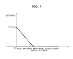
- FIG. 7 is an illustrative characteristic diagram illustrating a set target deceleration according to this implementation of the present invention.
- FIG. 8 is an illustrative view illustrating modification of a brake booster characteristic according to this implementation of the present invention.
- FIG. 9 is an illustrative view illustrating respective phases of the overtaking travel control according to this implementation of the present invention.
- FIG. 10 is an illustrative view illustrating a vehicle that returns to the original travel lane in response to failsafe control executed as the vehicle accelerates following a lane change, according to this implementation of the present invention.
- a reference numeral 1 denotes a travel control apparatus for a vehicle.
- input devices including a peripheral environment recognition device 11 , a travel parameter detection device 12 , a vehicle position information detection device 13 , a vehicle-to-vehicle communication device 14 , a road traffic information communication device 15 , and a switch group 16 , and output apparatuses including an engine control device 21 , a brake control device 22 , a steering control device 23 , a display device 24 , and a speaker/buzzer 25 are connected to a travel controller 10 .
- the peripheral environment recognition device 11 is constituted by a camera device (a stereo camera, a monocular camera, a color camera, or the like) that includes a solid state imaging device or the like and is provided in a vehicle cabin of a vehicle equipped with travel control apparatus 1 (hereinafter referred to as “the vehicle”) in order to obtain image information by photographing an external environment of the vehicle, a radar device (a laser radar, a millimeter wave radar, or the like) that receives reflection waves from three-dimensional objects existing on the periphery of the vehicle, a sonar, and so on (none of the above are illustrated in the drawings).
- a camera device a stereo camera, a monocular camera, a color camera, or the like
- the vehicle includes a solid state imaging device or the like and is provided in a vehicle cabin of a vehicle equipped with travel control apparatus 1 (hereinafter referred to as “the vehicle”) in order to obtain image information by photographing an external environment of the vehicle, a radar device (a laser radar, a millimeter wave radar
- the peripheral environment recognition device 11 performs known grouping processing, for example, in relation to distance information on the basis of the image information photographed by the camera device, and by comparing the grouped distance information with preset three-dimensional road shape data, three-dimensional object data, and so on, extracts positions (distances and angles), as well as speeds, of lane division line data, side wall data indicating guard rails and curbstones existing alongside a road, three-dimensional object data indicating vehicles and the like, and so on relative to a vehicle.
- the peripheral environment recognition device 11 also detects positions (distances and angles), as well as speeds, of three-dimensional objects from which reflection waves are received on the basis of reflection wave information obtained by the radar apparatus. Note that in this implementation, a maximum distance (a distance to a three-dimensional object or the farthest distance of the lane division line) that can be recognized by the peripheral environment recognition device 11 is set as a visibility limit. In one implementation, the peripheral environment recognition device 11 may serve as a travel environment information acquisition unit.
- the failure in the peripheral environment recognition device 11 is output to the travel controller 10 .
- the travel parameter detection device 12 detects travel information relating to the vehicle, more specifically a vehicle speed V, a steering torque Tdrv, a steering angle ⁇ H, a yaw rate ⁇ , an accelerator opening, a throttle opening, a road surface gradient Ug (an uphill gradient will be indicated by “+”) of a travel road surface, an estimated road surface friction coefficient value ⁇ e, and so on.
- the travel parameter detection device 12 may be provided as a travel information detector.
- the vehicle position information detection device 13 is a conventional navigation system, for example, which receives radio waves emitted by a global positioning system (GPS) satellite, detects a current position on the basis of the radio wave information, and specifies the position of the vehicle on map data stored in advance on a flash memory, a compact disc (CD), a digital versatile disc (DVD), a Blu-ray (registered trademark) disc, a hard disk drive (HDD), or the like, for example.
- GPS global positioning system
- CD compact disc
- DVD digital versatile disc
- HDD hard disk drive
- the pre-stored map data include road data and facility data.
- the road data include link position information, link type information, node position information, node type information, information indicating connection relationships between the nodes and the links, or in other words information indicating branching and convergence locations on the road, information indicating a maximum vehicle speed on branch roads, and so on.
- the facility data include a plurality of records relating to respective facilities, and each record includes information data indicating the name position and facility type (a department store, a store, a restaurant, a parking lot, a park, a location for repairing broken-down vehicles) of a subject facility.
- the vehicle position information detection device 13 may be provided as the travel environment information acquisition unit.
- the vehicle-to-vehicle communication device 14 is constituted by a short range wireless communication device having a communication area of approximately 100 [m], such as a wireless LAN, for example, and is capable of communicating directly with another vehicle without passing through a server or the like so as to exchange information with the other vehicle. Through mutual communication with the other vehicle, the vehicle-to-vehicle communication device 14 exchanges vehicle information, travel information, traffic environment information, and so on.
- the vehicle information includes unique information indicating a vehicle type (in this implementation, a passenger vehicle, a truck, a motorcycle, and so on).
- the travel information includes vehicle speed and vehicle position information, information indicating whether or not a brake lamp is illuminated, information indicating whether or not a direction indicator used to indicate a right or left turn is flashing, and information indicating whether or not a hazard lamp used during an emergency stop is flashing.
- the traffic environment information includes information that varies in accordance with the condition of road congestion information, construction work information, and so on.
- the vehicle-to-vehicle communication device 14 may be provided as the travel environment information acquisition unit.
- the road traffic information communication device 15 receives road traffic information relating to congestion, accidents, construction work, required times, and parking lots in real time from an FM multiplex broadcast or a transmitter disposed on the road using a so-called Vehicle Information and Communication System (VICS; registered trademark), and displays the received traffic information on the pre-stored map data described above.
- VICS Vehicle Information and Communication System
- the road traffic information communication device 15 may be provided as the travel environment information acquisition unit.
- the switch group 16 is a group of switches relating to control for assisting driving by a driver, and is constituted by, for example, a switch for executing travel control at a preset fixed speed or a switch for executing following control to maintain an inter-vehicle distance and an inter-vehicle time to a preceding vehicle at preset fixed values, a switch for executing lane keep control for controlling travel so that the vehicle stays in a set travel lane, a switch for executing lane deviation prevention control to prevent the vehicle from deviating from the travel lane, a switch for permitting execution of overtaking control in order to overtake a preceding vehicle (an overtaking target vehicle), a switch for executing automatic driving control, in which all of these control operations are performed in a coordinated fashion, a switch for setting the vehicle speed, inter-vehicle distance, inter-vehicle time, speed limit, and so on required in the respective control operations, a switch for canceling the respective control operations, and so on.
- the engine control device 21 is a conventional control unit that performs main control such as fuel injection control, ignition timing control, control of an electronically controlled throttle valve, and the like on an engine (not illustrated) of the vehicle on the basis of an intake air amount, a throttle opening, an engine water temperature, an intake air temperature, an oxygen concentration, a crank angle, the accelerator opening, and other vehicle information, for example.
- the brake control device 22 controls a braking system including a hydraulic unit and an electric booster, for example (neither of which are illustrated in the drawings).
- the hydraulic unit is capable of activating brake devices of four wheels independently of a brake operation performed by the driver, and the brake control device 22 uses the hydraulic unit to perform yaw moment control (yaw brake control) to apply a yaw moment to the vehicle by means of a conventional antilock brake system (ABS) function, an antiskid control function for stabilizing vehicle behavior, or the like on the basis of the brake switch, wheel speeds of the four wheels, the steering angle ⁇ H, the yaw rate ⁇ , and other vehicle information, for example.
- ABS antilock brake system
- the brake control device 22 can calculate a brake fluid pressure of each wheel on the basis of the brake forces, and generate braking force to decelerate the vehicle automatically and apply a yaw moment to the vehicle by means of yaw brake control.
- the brake control device 22 modifies a unique stability factor A of the vehicle (to a preset value Af that is larger than a normal value), calculates a target yaw rate ⁇ t using the stability factor Af, and executes yaw brake control to reduce the yaw rate ⁇ on the basis of the target yaw rate ⁇ t.
- the electric booster is basically used to assist a brake pedal depression force with thrust from an electric motor.
- the electric booster is capable of converting motor torque generated by the electric motor into assist thrust via a ball screw or the like, and applying the assist thrust to a master cylinder piston.
- the brake control device 22 can calculate the assist thrust on the basis of the brake force and generate braking force required for automatic deceleration control.
- the brake control device 22 modifies a braking force characteristic generated in accordance with the brake pedal depression force obtained in a brake operation performed by the driver from a normal characteristic in a direction for increasing the braking force value and a braking force generation response corresponding to the brake pedal depression force. The brake control device 22 then generates the braking force on the basis of the modified characteristic.
- the steering control device 23 is a conventional control device that controls an assist torque generated by an electric power steering motor (not illustrated) provided in the steering system of the vehicle on the basis of the vehicle speed, a steering torque, the steering angle, the yaw rate, and other vehicle information, for example.
- the steering control device 23 is also capable of lane keep control for controlling travel so that the vehicle stays in the set travel lane, and lane deviation prevention control to prevent the vehicle from deviating from the travel lane. Accordingly, when one of the steering angle and the steering torque required for the lane keep control and the lane deviation prevention control is calculated by the travel controller 10 and input into the steering control device 23 , the steering control device 23 drive-controls the electric power steering motor in accordance with the input control amounts. Further, the steering control device 23 detects a failure in the steering system, which includes a steering mechanism, a steering torque sensor, a steering angle sensor, and so on, and these failures are monitored by the travel controller 10 .
- the display device 24 is a device for providing the driver with visual warnings and notifications, such as a monitor, a display, or an alarm lamp, for example.
- the speaker/buzzer 25 is a device for providing the driver with aural warnings and notifications. When a failure occurs in one of various devices of the vehicle, the display device 24 and the speaker/buzzer 25 issue warnings to the driver as appropriate.
- the travel controller 10 detects an overtaking target vehicle in front of the vehicle in the same travel lane on the basis of the input signals from the respective devices 11 to 16 described above, and executes overtaking control to overtake the overtaking target vehicle using automatic driving control.
- the travel controller 10 modifies the overtaking control by activating required substitute control in accordance with the travel environment information obtained most recently before detecting the failure in the travel environment information acquisition unit, information relating to the overtaking target vehicle, the travel information, and conditions during the overtaking control.
- the yaw brake control is executed to reduce the yaw rate ⁇ of the vehicle.
- the vehicle is returned to the travel lane prior to the lane change by activating the yaw brake control to apply a yaw moment to the vehicle using a brake force, whereupon deceleration control is executed in accordance with the visibility limit of the most recently detected travel environment information.
- deceleration control is executed in accordance with the vehicle speed of the overtaking target vehicle in order to retreat to a predetermined relative position assumed to be behind the overtaking target vehicle.
- the vehicle is then returned to the travel lane prior to the lane change by activating the yaw brake control to apply a yaw moment to the vehicle using a brake force, whereupon deceleration control is executed in accordance with the visibility limit of the most recently detected travel environment information.
- a lane change is performed to the original travel lane by activating the yaw brake control to apply a yaw moment to the vehicle using a brake force.
- the travel controller 10 may be provided as an overtaking controller.
- the travel controller 10 executes overtaking travel control in four phases, namely an overtaking start lane change phase P 1 , an overtaking acceleration first half phase P 2 , an overtaking acceleration second half phase P 3 , and an original lane returning lane change phase P 4 . Travel control executed in each of these phases will be described below.
- FIG. 2 is a flowchart illustrating an overall overtaking travel control program.
- a vehicle trajectory of the vehicle during a lane change is assumed to be determined from a normalization polynomial of a minimum jerk ( ⁇ d 3 y/dx 3 ) trajectory on a two-dimensional coordinate system on which a travel distance is set as an x direction and a lateral movement amount (a lane change width) is set as a y direction, for example.
- Equations (2), (3), (4), illustrated below are obtained.
- dy/dx 30 ⁇ ( x 4 ⁇ 2 ⁇ x 3 +x 2 )
- d 2 y/dx 2 60 ⁇ (2 ⁇ x 3 ⁇ 3 ⁇ x 2 +x )
- d 3 y/dx 3 60 ⁇ (6 ⁇ x 2 ⁇ 6 ⁇ x+ 1)
- Equation (5) ( 3 ⁇ 3 1/2 )/6 (5)
- Equation (3) When d 2 y/dx 2 is calculated from this value of x using Equation (3), and a resulting normalized curvature value is set as an absolute value
- 10 ⁇ 3 1/2 /3 ⁇ 5.77 (6)
- Equation (8) (5.77 ⁇ W ⁇ V 2 /( d 2 Y/dt 2 )max_ c ) 1/2 (8)
- Equation (9) a distance L 1 required in the overtaking start lane change phase P 1 corresponds to Equation (9) illustrated below, in which the vehicle speed V at that time is V 1 .
- L 1 (5.77 ⁇ W ⁇ V 1 2 /( d 2 Y/dt 2 )max_ c ) 1/2 (9)
- Equation (12) A relationship between the target yaw rate ⁇ t, the vehicle speed V, and the lateral acceleration (d 2 y/dx 2 ) is expressed by Equation (11), illustrated below, and therefore the target yaw rate ⁇ t can be expressed by Equation (12), illustrated below, using Equation (3).
- ⁇ t ⁇ V ( d 2 y/dx 2 ) ⁇ W /( L/V ) 2 (11)
- ⁇ t 60 ⁇ (2 ⁇ xe 3 ⁇ 3 ⁇ xe 2 +xe ) ⁇ W ⁇ V/L 2 (12)
- Equation (13) the target steering angle ⁇ Ht required for the control (i.e. to be output to the steering control device 23 ) is determined.
- ⁇ Ht ⁇ t ⁇ n/G ⁇ (13)
- n is a steering gear ratio
- G ⁇ is a yaw rate gain.
- A is the unique stability factor of the vehicle, and 1 is a wheel base.
- the present invention is not limited to this example, and the vehicle trajectory may be approximated using another curve function or the like.
- the overtaking acceleration first half phase P 2 of FIG. 9 is executed in S 102 .
- a travel distance L 2 in the overtaking acceleration first half phase P 2 can be calculated using Equation (15), illustrated below, for example.
- L 2 (1/(2 ⁇ ( d 2 X/dt 2 ) t )) ⁇ ( V 2 2 ⁇ V 1 2 ) (15)
- V 2 is a target vehicle speed following overtaking acceleration, and takes the smaller value of a value (Vf+ ⁇ V) obtained by adding a preset predetermined speed (in other words, a (target) relative speed during overtaking) ⁇ V to a vehicle speed Vf of the overtaking target vehicle, and a speed limit Vlim (a preset speed limit or the speed limit of the road, which is recognized from the respective input signals described above), for example.
- a preset predetermined speed in other words, a (target) relative speed during overtaking
- Vlim a preset speed limit or the speed limit of the road, which is recognized from the respective input signals described above
- (d 2 X/dt 2 ) t is a target overtaking acceleration, which is set using Equation (16), illustrated below, for example.
- ( d 2 X/dt 2 ) t min(( d 2 X/dt 2 )0 ⁇ Kg ⁇ Ug, ⁇ e ⁇ g ) (16)
- min denotes a minimum function for selecting the smaller of ((d 2 X/dt 2 ) 0 ⁇ Kg ⁇ Ug) and ( ⁇ e ⁇ g), (d 2 X/dt 2 ) 0 denotes a preset reference value of the overtaking acceleration, Kg denotes the road surface gradient coefficient, and g denotes the gravitational acceleration.
- a travel distance L 3 in the overtaking acceleration second half phase P 3 can be calculated using Equation (17), illustrated below, for example.
- L 3 ( Lp ⁇ (1/(2 ⁇ ( d 2 X/dt 2 ) t )) ⁇ ( V 2 ⁇ V 1) 2 ) ⁇ V 2/( V 2 ⁇ V 1) (17)
- Lp is a value obtained by adding a target inter-vehicle distance following overtaking to the inter-vehicle distance relative to the overtaking target vehicle.
- a travel distance Lr covered during the overtaking control executed by the travel controller 10 according to this implementation is L 1 +L 2 +L 3 +L 4 .
- the routine advances to S 202 , and when the automatic driving condition is not established, the program is terminated.
- S 202 a determination is made as to whether or not an overtaking travel control condition is established.
- the routine advances to S 203 , and when it is determined that the overtaking travel control condition is not established, the program is terminated.
- S 203 a determination is made as to whether or not an acquisition failure of the travel environment information has been detected and a failure has been detected in the steering system of the vehicle.
- the routine advances to S 204 , and when either acquisition of the travel environment information or the steering system of the vehicle is normal, the program is terminated.
- a determination is made as to whether or not the original lane returning lane change phase P 4 is underway (whether or not Fp 4 1).
- a notification indicating that the lane change for overtaking the overtaking target vehicle by automatic driving is to be cancelled is issued through one of the display device 24 and the speaker/buzzer 25 .
- the routine then advances to S 302 , where the lane change for overtaking the overtaking target vehicle by automatic driving is cancelled.
- the routine is terminated as is.
- the routine advances to S 304 , where a signal is output to the brake control device 22 to instruct the brake control device 22 to execute the yaw brake control in order to reduce the yaw rate ⁇ by modifying the unique stability factor A of the vehicle (to the value Af that is larger than normal (in an under steering direction)). Accordingly, the brake control device 22 executes the yaw brake control to reduce the yaw rate ⁇ , whereby the vehicle behavior is stabilized.
- the brake control device 22 calculates the target yaw rate ⁇ t using Equation (19), illustrated below, for example, and then performs the yaw brake control to align the yaw rate ⁇ of the vehicle body with the target yaw rate ⁇ t.
- ⁇ t (1/(1+ Af ⁇ V 2 )) ⁇ ( V/ 1) ⁇ ( ⁇ H/n ) (19)
- a notification indicating that acceleration for overtaking the overtaking target vehicle by automatic driving is to be cancelled is issued through one of the display device 24 and the speaker/buzzer 25 .
- the routine then advances to S 402 , where acceleration for overtaking the overtaking target vehicle by automatic driving is cancelled.
- the routine advances to S 403 , where a determination is made as to whether or not the overtaking target vehicle exists in the original lane on the basis of the travel environment information detected most recently before the failure relating to acquisition of the travel environment information.
- the routine jumps to S 406 .
- the vehicle speed V of the vehicle is reduced by a predetermined (preset) deceleration until the vehicle speed V falls below the vehicle speed Vf of the overtaking target vehicle.
- the routine advances to S 405 . Note that a value detected most recently is used as the vehicle speed Vf of the overtaking target vehicle, while a value detected at regular intervals is used as the vehicle speed V of the vehicle.
- the routine returns to S 404 , and when the inter-vehicle distance LD between the overtaking target vehicle and the vehicle equals or exceeds the threshold LDt (LD ⁇ LDt), the routine advances to S 406 .
- LD ⁇ LDt threshold LDt
- the routine advances to S 407 , where the target steering angle ⁇ Ht is calculated on the basis of Equation (13) and so on, for example.
- a target yaw moment Mzt of the yaw brake control is calculated on the basis of Equation (20), illustrated below, for example.
- Mzt (2 ⁇ 1 ⁇ Kf ⁇ Kr )/( Kf+Kr ) ⁇ ( ⁇ Ht/n ) (20)
- Kf denotes an equivalent cornering power of the front wheels
- Kr denotes an equivalent cornering power of the rear wheels
- the routine advances to S 409 , where the target deceleration (d 2 X/dt 2 ) t is set on the basis of the visibility limit of the travel environment information detected most recently prior to the failure relating to acquisition of the travel environment information by referring to a map of the target deceleration (d 2 X/dt 2 ) t such as that illustrated in FIG. 7 , for example.
- the target deceleration (d 2 X/dt 2 ) t is set on the basis of the information indicating the most recently obtained visibility limit so as to increase steadily as the vehicle continues to travel.
- the vehicle when failures occur in the steering system and in relation to the travel environment information acquisition, the vehicle is decelerated at a steadily higher deceleration in accordance with the continuous travel distance, thereby ensuring that the vehicle can be stopped and safety can be secured reliably in the vehicle.
- the target deceleration (d 2 X/dt 2 ) t is set at zero, thereby avoiding a situation in which the lane change realized by performing the yaw brake control on the vehicle is impaired due to deceleration.
- a brake force of the respective wheels (a brake force Ffi of a turn inner side front wheel, a brake force Ffo of a turn outer side front wheel, a brake force Fri of a turn inner side rear wheel, and a brake force Fro of a turn outer side rear wheel) is calculated using Equations (21) to (24), illustrated below, and output to the brake control device 22 .
- Ffi ( drx/ 2) ⁇ Fx+dry ⁇ Fy (21)
- Ffo ( drx/ 2) ⁇ Fx ⁇ dry ⁇ Fy (22)
- Fri ((1 ⁇ drx )/2) ⁇ Fx +(1 ⁇ dry ) ⁇ Fy (23)
- Fro ((1 ⁇ drx )/2) ⁇ Fx ⁇ (1 ⁇ dry ) ⁇ Fy (24)
- Fx is a sum of brake forces corresponding to the target deceleration (d 2 X/dt 2 ) t, and is calculated using Equation (25) illustrated below, in which m denotes the vehicle mass.
- Fx ⁇ m ⁇ ( d 2 X/dt 2 ) t (25)
- Fy is a sum of left-right wheel brake force differences corresponding to the target yaw moment Mzt, and is calculated using Equation (26) illustrated below, in which d denotes the tread.
- Fy Mzt/d (26)
- drx is a front-rear braking force distribution ratio (front wheel side braking force/total braking force) of the deceleration control
- dry is a front-rear axle distribution (yaw moment of front axle/total yaw moment) of the yaw moment control.
- the routine then advances to S 411 , where the brake control device 22 is instructed to modify the characteristic of the braking force generated in accordance with the brake pedal depression force obtained by the driver during a brake operation from the normal characteristic in the direction (see FIG. 8 ) for increasing the braking force value and the braking force generation response corresponding to the brake pedal depression force.
- This processing is performed to ensure that a collision is reliably avoided in a region where no travel environment information has been obtained. Note that at the moment when the system failure occurs and the notification/warning is issued, the driver may panic and perform an emergency braking operation. Therefore, the braking force characteristic may be set at a normal characteristic of the electric booster within the most recently detected visibility range.
- a notification indicating that a lane change is to be performed back to the original lane of the overtaking operation by yaw brake control is issued through one of the display device 24 and the speaker/buzzer 25 .
- the routine advances to S 502 , where the target steering angle ⁇ Ht is calculated on the basis of Equation (13) and so on, for example.
- the routine advances to S 503 , where the target yaw moment Mzt of the yaw brake control is calculated on the basis of Equation (20), for example.
- the routine advances to S 504 , where the brake force of the respective wheels (the brake force Ffi of the turn inner side front wheel, the brake force Ffo of the turn outer side front wheel, the brake force Fri of the turn inner side rear wheel, and the brake force Fro of the turn outer side rear wheel) is calculated using Equations (21) to (24), for example, and output to the brake control device 22 .
- the routine advances to S 505 , where the brake control device 22 is instructed to modify the characteristic of the braking force generated in accordance with the brake pedal depression force obtained by the driver during a brake operation from the normal characteristic in the direction (see FIG. 8 ) for increasing the braking force value and the braking force generation response corresponding to the brake pedal depression force.
- the brake control device 22 is instructed to modify the characteristic of the braking force generated in accordance with the brake pedal depression force obtained by the driver during a brake operation from the normal characteristic in the direction (see FIG. 8 ) for increasing the braking force value and the braking force generation response corresponding to the brake pedal depression force.
- the braking force characteristic may be set at the normal characteristic of the electric booster within the most recently detected visibility range.
- the travel controller 10 detects the overtaking target vehicle ahead of the vehicle in the same travel lane, and executes overtaking control to overtake the overtaking target vehicle using automatic driving control.
- the travel controller 10 modifies the overtaking control by activating required substitute control in accordance with the travel environment information obtained most recently before detecting the acquisition failure in the travel environment information acquisition unit, the information relating to the overtaking target vehicle, the travel information, and conditions during the overtaking control (more specifically, conditions while changing lanes in order to overtake the overtaking target vehicle, conditions while accelerating following the lane change, and conditions while changing lanes back to the original lane following the overtaking acceleration).
- failsafe control can be performed appropriately, and as a result, sufficient safety can be secured.
Landscapes
- Engineering & Computer Science (AREA)
- Transportation (AREA)
- Mechanical Engineering (AREA)
- Chemical & Material Sciences (AREA)
- Combustion & Propulsion (AREA)
- Automation & Control Theory (AREA)
- Human Computer Interaction (AREA)
- Control Of Driving Devices And Active Controlling Of Vehicle (AREA)
- Steering Control In Accordance With Driving Conditions (AREA)
- Traffic Control Systems (AREA)
- Regulating Braking Force (AREA)
- Game Theory and Decision Science (AREA)
- Health & Medical Sciences (AREA)
- Artificial Intelligence (AREA)
- Evolutionary Computation (AREA)
- Business, Economics & Management (AREA)
- Medical Informatics (AREA)
- Aviation & Aerospace Engineering (AREA)
- Radar, Positioning & Navigation (AREA)
- Remote Sensing (AREA)
- Physics & Mathematics (AREA)
- General Physics & Mathematics (AREA)
Applications Claiming Priority (2)
| Application Number | Priority Date | Filing Date | Title |
|---|---|---|---|
| JP2014-218514 | 2014-10-27 | ||
| JP2014218514A JP6035306B2 (ja) | 2014-10-27 | 2014-10-27 | 車両の走行制御装置 |
Publications (2)
| Publication Number | Publication Date |
|---|---|
| US20160114811A1 US20160114811A1 (en) | 2016-04-28 |
| US9776641B2 true US9776641B2 (en) | 2017-10-03 |
Family
ID=55698608
Family Applications (1)
| Application Number | Title | Priority Date | Filing Date |
|---|---|---|---|
| US14/923,236 Active US9776641B2 (en) | 2014-10-27 | 2015-10-26 | Travel control apparatus for vehicle |
Country Status (4)
| Country | Link |
|---|---|
| US (1) | US9776641B2 (zh) |
| JP (1) | JP6035306B2 (zh) |
| CN (1) | CN105539441B (zh) |
| DE (1) | DE102015117907A1 (zh) |
Cited By (3)
| Publication number | Priority date | Publication date | Assignee | Title |
|---|---|---|---|---|
| US20180061236A1 (en) * | 2015-03-18 | 2018-03-01 | Nec Corporation | Driving control device, driving control method, and vehicle-to-vehicle communication system |
| US9956958B2 (en) * | 2015-09-10 | 2018-05-01 | Toyota Jidosha Kabushiki Kaisha | Vehicle driving control device and control device |
| US20190080609A1 (en) * | 2017-09-13 | 2019-03-14 | Subaru Corporation | Traveling control apparatus of vehicle |
Families Citing this family (56)
| Publication number | Priority date | Publication date | Assignee | Title |
|---|---|---|---|---|
| JP6103716B2 (ja) * | 2014-06-17 | 2017-03-29 | 富士重工業株式会社 | 車両の走行制御装置 |
| JP6303956B2 (ja) * | 2014-09-24 | 2018-04-04 | 株式会社デンソー | 軸ずれ量推定装置 |
| JP6087969B2 (ja) * | 2015-03-23 | 2017-03-01 | 富士重工業株式会社 | 車両の走行制御装置 |
| JP6319192B2 (ja) * | 2015-05-29 | 2018-05-09 | トヨタ自動車株式会社 | 車速制限装置 |
| US10000124B2 (en) * | 2015-11-04 | 2018-06-19 | Zoox, Inc. | Independent steering, power, torque control and transfer in vehicles |
| US9802661B1 (en) | 2015-11-04 | 2017-10-31 | Zoox, Inc. | Quadrant configuration of robotic vehicles |
| KR101788183B1 (ko) * | 2015-12-28 | 2017-10-20 | 현대자동차주식회사 | 차량 및 그 제어방법 |
| WO2017138517A1 (ja) * | 2016-02-12 | 2017-08-17 | 本田技研工業株式会社 | 車両制御システム、車両制御方法、および車両制御プログラム |
| US10967876B2 (en) | 2016-03-09 | 2021-04-06 | Honda Motor Co., Ltd. | Vehicle control system, vehicle control method, and vehicle control program |
| JP6524943B2 (ja) * | 2016-03-17 | 2019-06-05 | 株式会社デンソー | 走行支援装置 |
| JP6429203B2 (ja) * | 2016-05-19 | 2018-11-28 | 本田技研工業株式会社 | 車両制御システム、車両制御方法、および車両制御プログラム |
| JP6808992B2 (ja) * | 2016-06-17 | 2021-01-06 | 株式会社デンソー | 走行支援装置 |
| KR101899394B1 (ko) * | 2016-09-01 | 2018-09-17 | 국민대학교산학협력단 | 안전제한타원을 이용한 차량의 자율주행시스템 및 이를 이용한 자율주행방법 |
| CN106364486B (zh) * | 2016-09-08 | 2019-08-27 | 江苏大学 | 一种基于危害分析的智能车辆变道控制方法 |
| US20180143641A1 (en) * | 2016-11-23 | 2018-05-24 | Futurewei Technologies, Inc. | Motion controlling method for an autonomous vehicle and a computer device |
| JP6677822B2 (ja) * | 2016-12-07 | 2020-04-08 | 本田技研工業株式会社 | 車両制御装置 |
| JP6642399B2 (ja) * | 2016-12-07 | 2020-02-05 | トヨタ自動車株式会社 | 車両走行制御装置 |
| JP6583252B2 (ja) * | 2016-12-27 | 2019-10-02 | トヨタ自動車株式会社 | 運転支援装置 |
| CN106530833A (zh) * | 2016-12-29 | 2017-03-22 | 江苏大学 | 一种基于车联网的自动驾驶汽车智能变道系统及其控制方法 |
| US11307591B2 (en) | 2017-01-24 | 2022-04-19 | Honda Motor Co., Ltd. | Vehicle control system, vehicle control method, and vehicle control program |
| CN110290997B (zh) * | 2017-02-21 | 2022-06-17 | 日立安斯泰莫株式会社 | 车辆控制装置 |
| JP6773215B2 (ja) * | 2017-04-14 | 2020-10-21 | 日産自動車株式会社 | 車両制御方法及び車両制御装置 |
| JP6624158B2 (ja) | 2017-05-22 | 2019-12-25 | 株式会社デンソー | 電子制御装置 |
| JP6801591B2 (ja) | 2017-06-06 | 2020-12-16 | トヨタ自動車株式会社 | 操舵支援装置 |
| US10913495B2 (en) * | 2017-06-12 | 2021-02-09 | Steering Solutions Ip Holding Corporation | Vehicle safety steering system |
| JP6834805B2 (ja) | 2017-06-23 | 2021-02-24 | 株式会社デンソー | 電子制御装置 |
| DE102017212172B4 (de) | 2017-07-17 | 2021-01-28 | Audi Ag | Verfahren zum Betrieb eines Überholassistenzsystems eines Kraftfahrzeugs und Kraftfahrzeug |
| US10521974B2 (en) * | 2017-08-28 | 2019-12-31 | GM Global Technology Operations LLC | Method and apparatus for monitoring an autonomous vehicle |
| JP6898645B2 (ja) * | 2017-08-28 | 2021-07-07 | 株式会社Subaru | 自動操舵システム |
| JP6568560B2 (ja) * | 2017-09-15 | 2019-08-28 | 株式会社Subaru | 車両の走行制御装置 |
| JP6889274B2 (ja) * | 2017-10-17 | 2021-06-18 | 本田技研工業株式会社 | 走行モデル生成システム、走行モデル生成システムにおける車両、処理方法およびプログラム |
| CN107839687A (zh) * | 2017-10-18 | 2018-03-27 | 哈尔滨工业大学深圳研究生院 | 基于驾驶特性分析的最优自主超车控制方法 |
| CN107909837A (zh) * | 2017-10-24 | 2018-04-13 | 华为技术有限公司 | 一种车辆借道通行的方法和控制中心 |
| DE102017010716A1 (de) * | 2017-11-10 | 2019-05-16 | Knorr-Bremse Systeme für Nutzfahrzeuge GmbH | System zum wenigstens teilautonomen Betrieb eines Kraftfahrzeugs mit doppelter Redundanz |
| JP6907895B2 (ja) * | 2017-11-15 | 2021-07-21 | トヨタ自動車株式会社 | 自動運転システム |
| US20190168803A1 (en) * | 2017-12-06 | 2019-06-06 | Trw Automotive U.S. Llc | Method of controlling a vehicle in case of steering system failure |
| KR102037037B1 (ko) * | 2018-01-17 | 2019-10-28 | 현대모비스 주식회사 | 차량의 긴급 제동 제어 방법 |
| JP6979366B2 (ja) * | 2018-02-07 | 2021-12-15 | 本田技研工業株式会社 | 車両制御装置、車両制御方法、及びプログラム |
| JP7032178B2 (ja) * | 2018-03-02 | 2022-03-08 | トヨタ自動車株式会社 | 車両制御装置 |
| JP7152165B2 (ja) * | 2018-03-02 | 2022-10-12 | トヨタ自動車株式会社 | 車両制御装置 |
| US11521437B2 (en) * | 2018-03-05 | 2022-12-06 | Mitsubishi Electric Corporation | In-vehicle device, information processing method, and computer readable medium |
| JP7043295B2 (ja) * | 2018-03-07 | 2022-03-29 | 本田技研工業株式会社 | 車両制御装置、車両制御方法、およびプログラム |
| US10380897B1 (en) * | 2018-03-26 | 2019-08-13 | GM Global Technology Operations LLC | Vehicle systems and methods for sharing target vehicle video during passing events |
| DE102018204900B4 (de) * | 2018-03-29 | 2021-02-25 | Volkswagen Aktiengesellschaft | Bremssystem für ein Fahrzeug mit einer zumindest teilautomatisierten Steuerungsfunktion |
| CN108944866B (zh) * | 2018-07-06 | 2021-06-01 | 长春工业大学 | 一种改善转向与制动协同控制的自适应模型预测控制算法 |
| KR102474613B1 (ko) * | 2018-08-23 | 2022-12-06 | 현대자동차주식회사 | 차량의 어드밴스 관성주행제어방법 |
| KR102506879B1 (ko) * | 2018-11-23 | 2023-03-08 | 현대자동차주식회사 | 차량의 자율주행 제어 장치 및 방법 |
| KR102555915B1 (ko) * | 2018-12-12 | 2023-07-18 | 현대자동차주식회사 | 차량의 주행 제어장치 및 그 방법 |
| DE102018222670A1 (de) * | 2018-12-20 | 2020-06-25 | Robert Bosch Gmbh | Verfahren und Vorrichtung zum Bestimmen eines idealisierten Überholvorgangs |
| WO2020152778A1 (ja) * | 2019-01-22 | 2020-07-30 | 本田技研工業株式会社 | 同行移動体 |
| JP7194640B2 (ja) * | 2019-05-16 | 2022-12-22 | 本田技研工業株式会社 | 車両制御装置、車両制御方法、およびプログラム |
| CN113911133A (zh) * | 2020-07-07 | 2022-01-11 | 罗伯特·博世有限公司 | 具有故障处理单元的驾驶员辅助系统 |
| JP2022173929A (ja) * | 2021-05-10 | 2022-11-22 | 京セラ株式会社 | 観察装置 |
| CN113682303B (zh) * | 2021-09-27 | 2023-07-07 | 岚图汽车科技有限公司 | 车辆转向的方法及系统 |
| CN113978451A (zh) * | 2021-10-26 | 2022-01-28 | 浙江吉利控股集团有限公司 | 车辆摆动预警方法、装置及计算机可读存储介质 |
| CN113990107A (zh) * | 2021-11-26 | 2022-01-28 | 格林美股份有限公司 | 一种汽车自动驾驶调度系统 |
Citations (16)
| Publication number | Priority date | Publication date | Assignee | Title |
|---|---|---|---|---|
| US5521579A (en) * | 1993-04-26 | 1996-05-28 | Mercedes-Benz Ag | Method for providing guiding assistance for a vehicle in changing lane |
| US20040193374A1 (en) * | 2003-03-28 | 2004-09-30 | Hac Aleksander B. | Collision avoidance with active steering and braking |
| US20060009910A1 (en) * | 2004-06-17 | 2006-01-12 | Frank Ewerhart | Lane changing assistant for motor vehicles |
| US20090088925A1 (en) * | 2007-09-27 | 2009-04-02 | Hitachi, Ltd. | Drive Assist System |
| US20110196592A1 (en) * | 2010-01-14 | 2011-08-11 | Ford Global Technologies, Llc | Method and device for assisting a lane change of a vehicle |
| JP2011162132A (ja) | 2010-02-12 | 2011-08-25 | Toyota Motor Corp | 自動運転装置 |
| US20110241862A1 (en) * | 2010-03-30 | 2011-10-06 | GM Global Technology Operations LLC | Method and system for ensuring operation of limited-ability autonomous driving vehicles |
| US20120203435A1 (en) * | 2011-02-08 | 2012-08-09 | Volvo Car Corporation | Brake assist system |
| US20120283907A1 (en) * | 2011-05-05 | 2012-11-08 | GM Global Technology Operations LLC | Lane centering fail-safe control using differential braking |
| US20130253793A1 (en) * | 2011-05-05 | 2013-09-26 | GM Global Technology Operations LLC | Optimal Fusion Of Electric Park Brake And Hydraulic Brake Sub-System Functions To Control Vehicle Direction |
| US20140136015A1 (en) * | 2011-08-31 | 2014-05-15 | Nissan Motor Co., Ltd. | Vehicle driving support apparatus |
| US20150120124A1 (en) * | 2013-10-30 | 2015-04-30 | Volkswagen Ag | Process and device to enable or disable an automatic driving function |
| US20150360684A1 (en) * | 2014-06-17 | 2015-12-17 | Fuji Jukogyo Kabushiki Kaisha | Travel control apparatus for vehicle |
| US20150360721A1 (en) * | 2014-06-17 | 2015-12-17 | Fuji Jukogyo Kabushiki Kaisha | Travel control apparatus for vehicle |
| US20160031371A1 (en) * | 2014-07-29 | 2016-02-04 | Denso Corporation | In-vehicle apparatus |
| US20160121906A1 (en) * | 2014-10-31 | 2016-05-05 | Fuji Jukogyo Kabushiki Kaisha | Travel control apparatus for vehicle |
Family Cites Families (5)
| Publication number | Priority date | Publication date | Assignee | Title |
|---|---|---|---|---|
| JP2003157500A (ja) * | 2001-11-22 | 2003-05-30 | Fujitsu Ltd | 安全走行支援装置,安全走行支援プログラム,及び安全走行支援方法 |
| EP2032406B1 (en) * | 2006-06-11 | 2011-08-10 | Volvo Technology Corporation | Method and apparatus for using an automated lane keeping system to maintain lateral vehicle spacing |
| JP5313448B2 (ja) * | 2006-11-20 | 2013-10-09 | アイシン・エィ・ダブリュ株式会社 | 走行状況判定方法及び走行状況判定装置 |
| EP2017162B1 (en) * | 2007-07-19 | 2013-06-12 | Nissan Motor Co., Ltd. | In-lane running support system, automobile and in-lane running support method |
| CN103646298B (zh) * | 2013-12-13 | 2018-01-02 | 中国科学院深圳先进技术研究院 | 一种自动驾驶方法及系统 |
-
2014
- 2014-10-27 JP JP2014218514A patent/JP6035306B2/ja active Active
-
2015
- 2015-10-21 CN CN201510686509.0A patent/CN105539441B/zh active Active
- 2015-10-21 DE DE102015117907.5A patent/DE102015117907A1/de active Pending
- 2015-10-26 US US14/923,236 patent/US9776641B2/en active Active
Patent Citations (16)
| Publication number | Priority date | Publication date | Assignee | Title |
|---|---|---|---|---|
| US5521579A (en) * | 1993-04-26 | 1996-05-28 | Mercedes-Benz Ag | Method for providing guiding assistance for a vehicle in changing lane |
| US20040193374A1 (en) * | 2003-03-28 | 2004-09-30 | Hac Aleksander B. | Collision avoidance with active steering and braking |
| US20060009910A1 (en) * | 2004-06-17 | 2006-01-12 | Frank Ewerhart | Lane changing assistant for motor vehicles |
| US20090088925A1 (en) * | 2007-09-27 | 2009-04-02 | Hitachi, Ltd. | Drive Assist System |
| US20110196592A1 (en) * | 2010-01-14 | 2011-08-11 | Ford Global Technologies, Llc | Method and device for assisting a lane change of a vehicle |
| JP2011162132A (ja) | 2010-02-12 | 2011-08-25 | Toyota Motor Corp | 自動運転装置 |
| US20110241862A1 (en) * | 2010-03-30 | 2011-10-06 | GM Global Technology Operations LLC | Method and system for ensuring operation of limited-ability autonomous driving vehicles |
| US20120203435A1 (en) * | 2011-02-08 | 2012-08-09 | Volvo Car Corporation | Brake assist system |
| US20120283907A1 (en) * | 2011-05-05 | 2012-11-08 | GM Global Technology Operations LLC | Lane centering fail-safe control using differential braking |
| US20130253793A1 (en) * | 2011-05-05 | 2013-09-26 | GM Global Technology Operations LLC | Optimal Fusion Of Electric Park Brake And Hydraulic Brake Sub-System Functions To Control Vehicle Direction |
| US20140136015A1 (en) * | 2011-08-31 | 2014-05-15 | Nissan Motor Co., Ltd. | Vehicle driving support apparatus |
| US20150120124A1 (en) * | 2013-10-30 | 2015-04-30 | Volkswagen Ag | Process and device to enable or disable an automatic driving function |
| US20150360684A1 (en) * | 2014-06-17 | 2015-12-17 | Fuji Jukogyo Kabushiki Kaisha | Travel control apparatus for vehicle |
| US20150360721A1 (en) * | 2014-06-17 | 2015-12-17 | Fuji Jukogyo Kabushiki Kaisha | Travel control apparatus for vehicle |
| US20160031371A1 (en) * | 2014-07-29 | 2016-02-04 | Denso Corporation | In-vehicle apparatus |
| US20160121906A1 (en) * | 2014-10-31 | 2016-05-05 | Fuji Jukogyo Kabushiki Kaisha | Travel control apparatus for vehicle |
Cited By (5)
| Publication number | Priority date | Publication date | Assignee | Title |
|---|---|---|---|---|
| US20180061236A1 (en) * | 2015-03-18 | 2018-03-01 | Nec Corporation | Driving control device, driving control method, and vehicle-to-vehicle communication system |
| US10621869B2 (en) * | 2015-03-18 | 2020-04-14 | Nec Corporation | Driving control device, driving control method, and vehicle-to-vehicle communication system |
| US9956958B2 (en) * | 2015-09-10 | 2018-05-01 | Toyota Jidosha Kabushiki Kaisha | Vehicle driving control device and control device |
| US20190080609A1 (en) * | 2017-09-13 | 2019-03-14 | Subaru Corporation | Traveling control apparatus of vehicle |
| US10839689B2 (en) * | 2017-09-13 | 2020-11-17 | Subaru Corporation | Traveling control apparatus of vehicle |
Also Published As
| Publication number | Publication date |
|---|---|
| CN105539441B (zh) | 2017-09-29 |
| CN105539441A (zh) | 2016-05-04 |
| JP6035306B2 (ja) | 2016-11-30 |
| US20160114811A1 (en) | 2016-04-28 |
| JP2016084038A (ja) | 2016-05-19 |
| DE102015117907A1 (de) | 2016-04-28 |
Similar Documents
| Publication | Publication Date | Title |
|---|---|---|
| US9776641B2 (en) | Travel control apparatus for vehicle | |
| US9764640B2 (en) | Travel control apparatus for vehicle | |
| US10274962B2 (en) | Vehicle traveling control apparatus | |
| US11703858B2 (en) | Autonomous driving control device | |
| US10266174B2 (en) | Travel control device for vehicle | |
| US9944294B2 (en) | Vehicle traveling control apparatus | |
| US10131355B2 (en) | Vehicle traveling control apparatus | |
| US9452760B2 (en) | Driving control apparatus for vehicle | |
| US10360461B2 (en) | Travel control device for vehicle | |
| US9809164B2 (en) | Travel control apparatus for vehicle | |
| US10632993B2 (en) | Travel control apparatus for vehicle | |
| US20180162390A1 (en) | Vehicle Control Device and Vehicle Control Method | |
| JP6654907B2 (ja) | 車両の走行制御装置 | |
| JP2017165216A (ja) | 車両の走行制御装置 | |
| JP2016084093A (ja) | 車両の走行制御システム | |
| JP6624677B2 (ja) | 車両の走行制御装置 | |
| JP6867770B2 (ja) | 車両の走行制御装置 | |
| JP6820734B2 (ja) | 車両の走行制御装置 | |
| JP6959892B2 (ja) | 車両制御システム | |
| JP6322109B2 (ja) | 車両の走行制御装置 | |
| JP6391395B2 (ja) | 車両の走行制御装置 | |
| JP2017121851A (ja) | 車両の走行制御装置 | |
| JP2016124310A (ja) | 車両の走行制御装置 | |
| JP6691404B2 (ja) | 車両の走行制御装置 |
Legal Events
| Date | Code | Title | Description |
|---|---|---|---|
| AS | Assignment |
Owner name: FUJI JUKOGYO KABUSHIKI KAISHA, JAPAN Free format text: ASSIGNMENT OF ASSIGNORS INTEREST;ASSIGNORS:MATSUNO, KOJI;HORIGUCHI, HARUNOBU;OYAMA, HAJIME;AND OTHERS;SIGNING DATES FROM 20150908 TO 20151019;REEL/FRAME:036884/0778 |
|
| AS | Assignment |
Owner name: SUBARU CORPORATION, JAPAN Free format text: CHANGE OF NAME;ASSIGNOR:FUJI JUKOGYO KABUSHIKI KAISHA;REEL/FRAME:042624/0886 Effective date: 20170401 |
|
| STCF | Information on status: patent grant |
Free format text: PATENTED CASE |
|
| MAFP | Maintenance fee payment |
Free format text: PAYMENT OF MAINTENANCE FEE, 4TH YEAR, LARGE ENTITY (ORIGINAL EVENT CODE: M1551); ENTITY STATUS OF PATENT OWNER: LARGE ENTITY Year of fee payment: 4 |