US9758310B2 - Article transport device - Google Patents
Article transport device Download PDFInfo
- Publication number
- US9758310B2 US9758310B2 US15/403,604 US201715403604A US9758310B2 US 9758310 B2 US9758310 B2 US 9758310B2 US 201715403604 A US201715403604 A US 201715403604A US 9758310 B2 US9758310 B2 US 9758310B2
- Authority
- US
- United States
- Prior art keywords
- support portion
- article
- travel
- along
- respect
- Prior art date
- Legal status (The legal status is an assumption and is not a legal conclusion. Google has not performed a legal analysis and makes no representation as to the accuracy of the status listed.)
- Active
Links
Images


Classifications
-
- B—PERFORMING OPERATIONS; TRANSPORTING
- B65—CONVEYING; PACKING; STORING; HANDLING THIN OR FILAMENTARY MATERIAL
- B65G—TRANSPORT OR STORAGE DEVICES, e.g. CONVEYORS FOR LOADING OR TIPPING, SHOP CONVEYOR SYSTEMS OR PNEUMATIC TUBE CONVEYORS
- B65G43/00—Control devices, e.g. for safety, warning or fault-correcting
-
- H—ELECTRICITY
- H01—ELECTRIC ELEMENTS
- H01L—SEMICONDUCTOR DEVICES NOT COVERED BY CLASS H10
- H01L21/00—Processes or apparatus adapted for the manufacture or treatment of semiconductor or solid state devices or of parts thereof
- H01L21/67—Apparatus specially adapted for handling semiconductor or electric solid state devices during manufacture or treatment thereof; Apparatus specially adapted for handling wafers during manufacture or treatment of semiconductor or electric solid state devices or components ; Apparatus not specifically provided for elsewhere
- H01L21/677—Apparatus specially adapted for handling semiconductor or electric solid state devices during manufacture or treatment thereof; Apparatus specially adapted for handling wafers during manufacture or treatment of semiconductor or electric solid state devices or components ; Apparatus not specifically provided for elsewhere for conveying, e.g. between different workstations
- H01L21/67703—Apparatus specially adapted for handling semiconductor or electric solid state devices during manufacture or treatment thereof; Apparatus specially adapted for handling wafers during manufacture or treatment of semiconductor or electric solid state devices or components ; Apparatus not specifically provided for elsewhere for conveying, e.g. between different workstations between different workstations
- H01L21/6773—Conveying cassettes, containers or carriers
-
- B—PERFORMING OPERATIONS; TRANSPORTING
- B66—HOISTING; LIFTING; HAULING
- B66C—CRANES; LOAD-ENGAGING ELEMENTS OR DEVICES FOR CRANES, CAPSTANS, WINCHES, OR TACKLES
- B66C13/00—Other constructional features or details
- B66C13/16—Applications of indicating, registering, or weighing devices
-
- B—PERFORMING OPERATIONS; TRANSPORTING
- B65—CONVEYING; PACKING; STORING; HANDLING THIN OR FILAMENTARY MATERIAL
- B65G—TRANSPORT OR STORAGE DEVICES, e.g. CONVEYORS FOR LOADING OR TIPPING, SHOP CONVEYOR SYSTEMS OR PNEUMATIC TUBE CONVEYORS
- B65G43/00—Control devices, e.g. for safety, warning or fault-correcting
- B65G43/08—Control devices operated by article or material being fed, conveyed or discharged
-
- B—PERFORMING OPERATIONS; TRANSPORTING
- B65—CONVEYING; PACKING; STORING; HANDLING THIN OR FILAMENTARY MATERIAL
- B65G—TRANSPORT OR STORAGE DEVICES, e.g. CONVEYORS FOR LOADING OR TIPPING, SHOP CONVEYOR SYSTEMS OR PNEUMATIC TUBE CONVEYORS
- B65G47/00—Article or material-handling devices associated with conveyors; Methods employing such devices
- B65G47/74—Feeding, transfer, or discharging devices of particular kinds or types
- B65G47/90—Devices for picking-up and depositing articles or materials
- B65G47/902—Devices for picking-up and depositing articles or materials provided with drive systems incorporating rotary and rectilinear movements
-
- B—PERFORMING OPERATIONS; TRANSPORTING
- B65—CONVEYING; PACKING; STORING; HANDLING THIN OR FILAMENTARY MATERIAL
- B65G—TRANSPORT OR STORAGE DEVICES, e.g. CONVEYORS FOR LOADING OR TIPPING, SHOP CONVEYOR SYSTEMS OR PNEUMATIC TUBE CONVEYORS
- B65G49/00—Conveying systems characterised by their application for specified purposes not otherwise provided for
- B65G49/05—Conveying systems characterised by their application for specified purposes not otherwise provided for for fragile or damageable materials or articles
- B65G49/06—Conveying systems characterised by their application for specified purposes not otherwise provided for for fragile or damageable materials or articles for fragile sheets, e.g. glass
- B65G49/061—Lifting, gripping, or carrying means, for one or more sheets forming independent means of transport, e.g. suction cups, transport frames
-
- B—PERFORMING OPERATIONS; TRANSPORTING
- B66—HOISTING; LIFTING; HAULING
- B66C—CRANES; LOAD-ENGAGING ELEMENTS OR DEVICES FOR CRANES, CAPSTANS, WINCHES, OR TACKLES
- B66C13/00—Other constructional features or details
- B66C13/04—Auxiliary devices for controlling movements of suspended loads, or preventing cable slack
- B66C13/08—Auxiliary devices for controlling movements of suspended loads, or preventing cable slack for depositing loads in desired attitudes or positions
-
- B—PERFORMING OPERATIONS; TRANSPORTING
- B66—HOISTING; LIFTING; HAULING
- B66C—CRANES; LOAD-ENGAGING ELEMENTS OR DEVICES FOR CRANES, CAPSTANS, WINCHES, OR TACKLES
- B66C13/00—Other constructional features or details
- B66C13/18—Control systems or devices
-
- H—ELECTRICITY
- H01—ELECTRIC ELEMENTS
- H01L—SEMICONDUCTOR DEVICES NOT COVERED BY CLASS H10
- H01L21/00—Processes or apparatus adapted for the manufacture or treatment of semiconductor or solid state devices or of parts thereof
- H01L21/67—Apparatus specially adapted for handling semiconductor or electric solid state devices during manufacture or treatment thereof; Apparatus specially adapted for handling wafers during manufacture or treatment of semiconductor or electric solid state devices or components ; Apparatus not specifically provided for elsewhere
- H01L21/67005—Apparatus not specifically provided for elsewhere
- H01L21/67242—Apparatus for monitoring, sorting or marking
- H01L21/67259—Position monitoring, e.g. misposition detection or presence detection
-
- H—ELECTRICITY
- H01—ELECTRIC ELEMENTS
- H01L—SEMICONDUCTOR DEVICES NOT COVERED BY CLASS H10
- H01L21/00—Processes or apparatus adapted for the manufacture or treatment of semiconductor or solid state devices or of parts thereof
- H01L21/67—Apparatus specially adapted for handling semiconductor or electric solid state devices during manufacture or treatment thereof; Apparatus specially adapted for handling wafers during manufacture or treatment of semiconductor or electric solid state devices or components ; Apparatus not specifically provided for elsewhere
- H01L21/677—Apparatus specially adapted for handling semiconductor or electric solid state devices during manufacture or treatment thereof; Apparatus specially adapted for handling wafers during manufacture or treatment of semiconductor or electric solid state devices or components ; Apparatus not specifically provided for elsewhere for conveying, e.g. between different workstations
- H01L21/67703—Apparatus specially adapted for handling semiconductor or electric solid state devices during manufacture or treatment thereof; Apparatus specially adapted for handling wafers during manufacture or treatment of semiconductor or electric solid state devices or components ; Apparatus not specifically provided for elsewhere for conveying, e.g. between different workstations between different workstations
- H01L21/67706—Mechanical details, e.g. roller, belt
-
- H—ELECTRICITY
- H01—ELECTRIC ELEMENTS
- H01L—SEMICONDUCTOR DEVICES NOT COVERED BY CLASS H10
- H01L21/00—Processes or apparatus adapted for the manufacture or treatment of semiconductor or solid state devices or of parts thereof
- H01L21/67—Apparatus specially adapted for handling semiconductor or electric solid state devices during manufacture or treatment thereof; Apparatus specially adapted for handling wafers during manufacture or treatment of semiconductor or electric solid state devices or components ; Apparatus not specifically provided for elsewhere
- H01L21/677—Apparatus specially adapted for handling semiconductor or electric solid state devices during manufacture or treatment thereof; Apparatus specially adapted for handling wafers during manufacture or treatment of semiconductor or electric solid state devices or components ; Apparatus not specifically provided for elsewhere for conveying, e.g. between different workstations
- H01L21/67703—Apparatus specially adapted for handling semiconductor or electric solid state devices during manufacture or treatment thereof; Apparatus specially adapted for handling wafers during manufacture or treatment of semiconductor or electric solid state devices or components ; Apparatus not specifically provided for elsewhere for conveying, e.g. between different workstations between different workstations
- H01L21/67712—Apparatus specially adapted for handling semiconductor or electric solid state devices during manufacture or treatment thereof; Apparatus specially adapted for handling wafers during manufacture or treatment of semiconductor or electric solid state devices or components ; Apparatus not specifically provided for elsewhere for conveying, e.g. between different workstations between different workstations the substrate being handled substantially vertically
-
- H—ELECTRICITY
- H01—ELECTRIC ELEMENTS
- H01L—SEMICONDUCTOR DEVICES NOT COVERED BY CLASS H10
- H01L21/00—Processes or apparatus adapted for the manufacture or treatment of semiconductor or solid state devices or of parts thereof
- H01L21/67—Apparatus specially adapted for handling semiconductor or electric solid state devices during manufacture or treatment thereof; Apparatus specially adapted for handling wafers during manufacture or treatment of semiconductor or electric solid state devices or components ; Apparatus not specifically provided for elsewhere
- H01L21/677—Apparatus specially adapted for handling semiconductor or electric solid state devices during manufacture or treatment thereof; Apparatus specially adapted for handling wafers during manufacture or treatment of semiconductor or electric solid state devices or components ; Apparatus not specifically provided for elsewhere for conveying, e.g. between different workstations
- H01L21/67703—Apparatus specially adapted for handling semiconductor or electric solid state devices during manufacture or treatment thereof; Apparatus specially adapted for handling wafers during manufacture or treatment of semiconductor or electric solid state devices or components ; Apparatus not specifically provided for elsewhere for conveying, e.g. between different workstations between different workstations
- H01L21/67733—Overhead conveying
-
- H—ELECTRICITY
- H01—ELECTRIC ELEMENTS
- H01L—SEMICONDUCTOR DEVICES NOT COVERED BY CLASS H10
- H01L21/00—Processes or apparatus adapted for the manufacture or treatment of semiconductor or solid state devices or of parts thereof
- H01L21/67—Apparatus specially adapted for handling semiconductor or electric solid state devices during manufacture or treatment thereof; Apparatus specially adapted for handling wafers during manufacture or treatment of semiconductor or electric solid state devices or components ; Apparatus not specifically provided for elsewhere
- H01L21/677—Apparatus specially adapted for handling semiconductor or electric solid state devices during manufacture or treatment thereof; Apparatus specially adapted for handling wafers during manufacture or treatment of semiconductor or electric solid state devices or components ; Apparatus not specifically provided for elsewhere for conveying, e.g. between different workstations
- H01L21/67703—Apparatus specially adapted for handling semiconductor or electric solid state devices during manufacture or treatment thereof; Apparatus specially adapted for handling wafers during manufacture or treatment of semiconductor or electric solid state devices or components ; Apparatus not specifically provided for elsewhere for conveying, e.g. between different workstations between different workstations
- H01L21/67736—Loading to or unloading from a conveyor
-
- H—ELECTRICITY
- H01—ELECTRIC ELEMENTS
- H01L—SEMICONDUCTOR DEVICES NOT COVERED BY CLASS H10
- H01L21/00—Processes or apparatus adapted for the manufacture or treatment of semiconductor or solid state devices or of parts thereof
- H01L21/67—Apparatus specially adapted for handling semiconductor or electric solid state devices during manufacture or treatment thereof; Apparatus specially adapted for handling wafers during manufacture or treatment of semiconductor or electric solid state devices or components ; Apparatus not specifically provided for elsewhere
- H01L21/677—Apparatus specially adapted for handling semiconductor or electric solid state devices during manufacture or treatment thereof; Apparatus specially adapted for handling wafers during manufacture or treatment of semiconductor or electric solid state devices or components ; Apparatus not specifically provided for elsewhere for conveying, e.g. between different workstations
- H01L21/67784—Apparatus specially adapted for handling semiconductor or electric solid state devices during manufacture or treatment thereof; Apparatus specially adapted for handling wafers during manufacture or treatment of semiconductor or electric solid state devices or components ; Apparatus not specifically provided for elsewhere for conveying, e.g. between different workstations using air tracks
- H01L21/67787—Apparatus specially adapted for handling semiconductor or electric solid state devices during manufacture or treatment thereof; Apparatus specially adapted for handling wafers during manufacture or treatment of semiconductor or electric solid state devices or components ; Apparatus not specifically provided for elsewhere for conveying, e.g. between different workstations using air tracks with angular orientation of the workpieces
-
- H—ELECTRICITY
- H01—ELECTRIC ELEMENTS
- H01L—SEMICONDUCTOR DEVICES NOT COVERED BY CLASS H10
- H01L21/00—Processes or apparatus adapted for the manufacture or treatment of semiconductor or solid state devices or of parts thereof
- H01L21/67—Apparatus specially adapted for handling semiconductor or electric solid state devices during manufacture or treatment thereof; Apparatus specially adapted for handling wafers during manufacture or treatment of semiconductor or electric solid state devices or components ; Apparatus not specifically provided for elsewhere
- H01L21/677—Apparatus specially adapted for handling semiconductor or electric solid state devices during manufacture or treatment thereof; Apparatus specially adapted for handling wafers during manufacture or treatment of semiconductor or electric solid state devices or components ; Apparatus not specifically provided for elsewhere for conveying, e.g. between different workstations
- H01L21/67793—Apparatus specially adapted for handling semiconductor or electric solid state devices during manufacture or treatment thereof; Apparatus specially adapted for handling wafers during manufacture or treatment of semiconductor or electric solid state devices or components ; Apparatus not specifically provided for elsewhere for conveying, e.g. between different workstations with orientating and positioning by means of a vibratory bowl or track
-
- H—ELECTRICITY
- H01—ELECTRIC ELEMENTS
- H01L—SEMICONDUCTOR DEVICES NOT COVERED BY CLASS H10
- H01L21/00—Processes or apparatus adapted for the manufacture or treatment of semiconductor or solid state devices or of parts thereof
- H01L21/67—Apparatus specially adapted for handling semiconductor or electric solid state devices during manufacture or treatment thereof; Apparatus specially adapted for handling wafers during manufacture or treatment of semiconductor or electric solid state devices or components ; Apparatus not specifically provided for elsewhere
- H01L21/677—Apparatus specially adapted for handling semiconductor or electric solid state devices during manufacture or treatment thereof; Apparatus specially adapted for handling wafers during manufacture or treatment of semiconductor or electric solid state devices or components ; Apparatus not specifically provided for elsewhere for conveying, e.g. between different workstations
- H01L21/67796—Apparatus specially adapted for handling semiconductor or electric solid state devices during manufacture or treatment thereof; Apparatus specially adapted for handling wafers during manufacture or treatment of semiconductor or electric solid state devices or components ; Apparatus not specifically provided for elsewhere for conveying, e.g. between different workstations with angular orientation of workpieces
-
- B—PERFORMING OPERATIONS; TRANSPORTING
- B65—CONVEYING; PACKING; STORING; HANDLING THIN OR FILAMENTARY MATERIAL
- B65G—TRANSPORT OR STORAGE DEVICES, e.g. CONVEYORS FOR LOADING OR TIPPING, SHOP CONVEYOR SYSTEMS OR PNEUMATIC TUBE CONVEYORS
- B65G2201/00—Indexing codes relating to handling devices, e.g. conveyors, characterised by the type of product or load being conveyed or handled
- B65G2201/02—Articles
- B65G2201/0297—Wafer cassette
-
- B—PERFORMING OPERATIONS; TRANSPORTING
- B65—CONVEYING; PACKING; STORING; HANDLING THIN OR FILAMENTARY MATERIAL
- B65G—TRANSPORT OR STORAGE DEVICES, e.g. CONVEYORS FOR LOADING OR TIPPING, SHOP CONVEYOR SYSTEMS OR PNEUMATIC TUBE CONVEYORS
- B65G2203/00—Indexing code relating to control or detection of the articles or the load carriers during conveying
- B65G2203/02—Control or detection
- B65G2203/0208—Control or detection relating to the transported articles
Definitions
- the present invention relates to an article transport device comprising a travel portion configured to travel along a travel path, a first support portion configured to support an article, an actuator configured to move the first support portion with respect to the travel portion along at least one of a plurality of perpendicular directions which are perpendicular to a direction along the travel path, and a controller configured to control operation of the actuator.
- Patent Document 1 describes an article transport device having a swiveling table [41] which can rotate an article supported by a vertically movable member [30] about a vertical axis, and also describes a control performed to rotate the article about the vertical axis by means of the swiveling table [41] to match the orientation of the article to the article receiving platform [5] which is a transport target location.
- Patent Document 1 describes, in Paragraphs 0038 and 0044, etc., an oscillation damping control for reducing any oscillation of the vertically movable member [30] which may occur when rotating the swiveling table [41] in such a manner.
- oscillation (back and forth motion) of the article supported by a first support portion may also occur simply by the traveling of the travel portion, without having to rotate the article about the vertical axis.
- Types of oscillations that can be expected to occur include, for example, a vertical oscillation of the article caused by a step or a curve in a rail along which the travel portion travels, and an oscillation of the article along the lateral width direction (path width direction) of the travel path caused by an inertial force, such as a centrifugal force, that acts on the article.
- an article transport device in which an oscillation of an article resulting from the traveling of a travel portion can be reduced by means of a relatively simple arrangement.
- an article transport device comprises: a travel portion configured to travel along a travel path; a first support portion configured to support an article; an actuator configured to move the first support portion with respect to the travel portion along at least one of a plurality of perpendicular directions which are perpendicular to a direction along the travel path; a controller configured to control operation of the actuator; a detector configured to detect a physical quantity that represents a motion, with respect to the travel portion, of the article supported by the first support portion along a moving direction along which the first support portion is moved with respect to the travel portion by the actuator; wherein the controller is configured to perform a transfer control and an oscillation damping control, wherein the transfer control is a control for controlling an operation of the actuator while the travel portion is at rest to cause the first support portion to be moved with respect to the travel portion between a first position within the travel path and a second position for transferring the article between the first support portion and a transport target location which is one of a transport origin and a transport destination for the article, and wherein
- the oscillation damping control performed by the controller the oscillation of the article supported by the first support portion that occurs while the travel portion is traveling (i.e., oscillation resulting from the traveling of the travel portion) can be reduced. And such reduction in the oscillation that occurs while the traveling portion is traveling is done by controlling the operation of the actuator provided to the article transport device for transferring an article between the article transport device and a transport target location.
- an oscillation damping control can be performed through an effective use of the actuator and a controller that are already provided to the article transport device, without having to provide a separate device exclusively for an oscillation damping control.
- the performance (processing power etc.) required of the controller is not increased excessively by requiring it to perform the oscillation damping control because the actuator is not operated for the purpose of transferring an article while the travel portion is traveling during which the oscillation damping control is performed, i.e., because the period in which the oscillation damping control is performed does not overlap with the period in which the transfer control is performed.
- an article transport device can be provided in which an oscillation of an article resulting from the traveling of a travel portion can be reduced by means of a relatively simple arrangement.
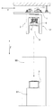
- FIG. 1 shows an article transport device with a first support portion located at a first position
- FIG. 2 shows the article transport device with the first support portion located at a second position
- FIG. 3 is a side view of the article transport device
- FIG. 4 is a front view of the article transport device
- FIG. 5 is a control block diagram
- FIG. 6 is a block diagram showing a control system for an oscillation damping control
- FIG. 7 is a drawing for describing an oscillation of an article along a path width direction
- FIG. 8 is a drawing for describing a first oscillation damping control
- FIG. 9 is a drawing for describing a vertical oscillation of an article
- FIG. 10 is a drawing for describing a second oscillation damping control
- FIG. 11 is a flow chart for a control.
- the article transport device 2 has a travel portion 11 configured to travel along a travel path, a first support portion 4 configured to support an article 3 , an actuator device 26 configured to move the first support portion 4 with respect to the travel portion 11 , and a controller 80 configured to control the operation of the actuator device 26 .
- the first support portion 4 is supported by the travel portion 11 , and is moved along the travel path as the travel portion 11 travels along the travel path.
- the article transport device 2 also has a second support portion 5 which is supported by the travel portion 11 , and which suspends and supports the first support portion 4 . And thus, the first support portion 4 is supported by the travel portion 11 through the second support portion 5 .
- the actuator device 26 is, or corresponds to, the “actuator”
- the controller device 80 is, or corresponds to, the “controller”.
- the actuator device 26 is configured to move the first support portion 4 with respect to the travel portion 11 along at least one of a plurality of perpendicular directions which are perpendicular to the direction along the travel path (referred to, hereinafter, as the “path longitudinal direction Y”).
- the actuator device 26 is configured to move the first support portion 4 with respect to the travel portion 11 along the path width direction X and the vertical direction Z direction respectively, which are two of the perpendicular directions.
- the path width direction X is the lateral width direction of the travel path. That is, the path width direction X is perpendicular to both the path longitudinal direction Y and the vertical direction Z.
- travel rails 1 are installed so that they extend along the path longitudinal direction Y as described below.
- the article transport device 2 is provided with detecting devices 40 each configured to detect a physical quantity (hereinafter “specific physical quantity”) that represents a motion, with respect to the travel portion 11 , of an article 3 supported by the first support portion 4 .
- Each detecting device 40 detects a specific physical quantity along a direction of movement of the first support portion 4 with respect to the travel portion 11 caused by the actuator device 26 .
- the directions of movement are the path width direction X and the vertical direction Z.
- each detecting device 40 detects the specific physical quantity along each of the path width direction X and the vertical direction Z.
- each detecting device 40 is, or corresponds to, the “detector”.
- the travel portion 11 travels along the travel path installed on the ceiling side (i.e., close to the ceiling).
- the travel path is an extent of space through which the travel portion 11 , a main body portion 12 , and an article 3 supported by the first support portion 4 move when the travel portion 11 travels.
- the main body portion 12 is a portion of the article transport device 2 that is supported by the travel portion 11 .
- the main body portion 12 includes the first support portion 4 and the second support portion 5 .
- the space through which the article 3 moves when the travel portion 11 travels is included in the space through which the main body portion 12 moves when the travel portion 11 travels.
- the travel path is formed such that it extends by way of, or adjacent, a plurality of transport target locations 91 .
- Any of the transport target locations 91 can serve as a transport origin or a transport destination for an article 3 that is being transported by the article transport device 2 .
- each article 3 is a container for holding one or more substrates, such as semiconductor substrates, and is, more specifically, a FOUP (Front Opening Unified Pod).
- the transport target location 91 shown in FIGS. 1 and 2 as an example is a support platform (load port) for a processing device 90 for processing the substrates that had been held in the article 3 .
- Each transport target location 91 is located, for example, in a position that is under the travel path and that overlaps with the travel path as seen along the vertical direction Z, or in a position that is under the travel path and that is located off to one or the other side of the travel path along the path width direction X as seen along the vertical direction Z.
- the travel portion 11 is configured to travel along the travel path while being supported by the travel rails 1 that are suspended from the ceiling.
- the main body portion 12 is suspended from, and supported by, the travel portion 11 such that the main body portion 12 is located below the travel rails 1 .
- the travel portion 11 has travel wheels 14 which roll on the top surfaces of the travel rails 1 .
- the travel portion 11 is supported by the travel rails 11 with the travel wheels 14 in contact with the travel rails 11 from above.
- a pair of travel rails 1 that are spaced apart from each other along the path width direction X are provided along the travel path.
- the travel portion 11 has travel wheels 14 that roll on the top surface of one of the pair of travel rails 1 and travel wheels 14 that roll on the top surface of the other of the pair of travel rails 1 .
- the travel portion 11 travels by means of the actuating force of the drive motors 13 (see FIG. 3 ) provided to the travel portion 11 . More specifically, the travel portion 11 travels along the travel path as a result of the fact that the travel wheels 14 are driven and rotated by the respective drive motors 13 .
- the travel portion 11 are provided with guide wheels 15 which restrict movement of the travel portion 11 along the path width direction X, and that the travel portion 11 travels along the direction along which the travel rails 1 extend (i.e., along the travel path) with the guide wheels 15 in contact with, and being guided by, the side surfaces of the travel rails 1 .
- the article transport device 2 is provided with a sliding mechanism 18 which is operated by the actuating force of the actuator device 26 and which is configured to move the second support portion 5 along the path width direction X with respect to the travel portion 11 . Because the second support portion 5 suspends and supports the first support portion 4 , as the second support portion 5 is moved along the path width direction X with respect to the travel portion 11 , the first support portion 4 is also moved to the same side along the path width direction X with respect to the travel portion 11 .
- the actuator device 26 is configured to move the first support portion 4 along the path width direction X with respect to the travel portion 11 by moving the second support portion 5 along the path width direction X with respect to the travel portion 11 , with the path width direction X being specified as one of the plurality of perpendicular directions.
- the actuator device 26 is configured to be capable of moving the second support portion 5 to both sides, along the path width direction X, of a reference position, along the path width direction X, for the traveling of the travel portion 11 (position of the second support portion 5 shown with phantom lines in FIG. 4 ).
- this reference position is a position within the travel path, and, in the present embodiment, is a position within the space (referred to, hereinafter, as the “holding space”) that is partitioned off at both ends along the path longitudinal direction Y by the cover 16 provided to the main body portion 12 .
- This holding space opens or communicates to the space outside the holding space (space outside the travel path) through an opening formed on at least one side (both sides in the present embodiment) along the path width direction X.
- first support portion 4 , the second support portion 5 , and the article 3 supported by the first support portion 4 are moved along the path width direction X through the opening and between inside and outside of the holding space (i.e., between inside and outside of the travel path) without coming into contact with the cover 16 .
- the actuator device 26 includes an electrical motor 25 (which will be referred to as a sliding movement motor for short and is a servo-motor in the present embodiment) for operating the sliding mechanism 18 .
- the sliding mechanism 18 includes a first slide movement member 23 and a second slide movement member 24 .
- the second slide movement member 24 is connected, for relative movement along the path width direction X, to a connecting portion of the main body portion 12 (upper portion of the main body portion 12 ) that connects the main body portion 12 to the travel portion 11 .
- the first slide movement member 23 is connected to the second slide movement member 24 for relative movement along the path width direction X.
- the second support portion 5 is fixed to the first slide movement member 23 , and is moved integrally with the first slide movement member 23 along the path width direction X. From the state in which the second support portion 5 is located at the aforementioned reference position (state shown with phantom lines in FIG.
- the actuator device 26 moves the second support portion 5 outward (direction away from the reference position) along the path width direction X by causing the second slide movement member 24 to be slid and moved outward along the path width direction X with respect to the aforementioned connecting portion of the main body portion 12 , and by causing the first slide movement member 23 to be slid and moved outward along the path width direction X with respect to the second slide movement member 24 , by means of the actuating force of the sliding movement motor 25 .
- the position (projected position) of the second support portion 5 shown with solid lines in FIG. 4 is such a position that the first support portion 4 overlaps, as seen along the vertical direction Z, with the transport target location 91 (not shown in FIG.
- the actuator device 26 moves the second support portion 5 inward (direction toward the reference position) along the path width direction X by causing the second slide movement member 24 to be slid and moved inward along the path width direction X with respect to the aforementioned connecting portion of the main body portion 12 , and by causing the first slide movement member 23 to be slid and moved inward along the path width direction X with respect to the second slide movement member 24 , by means of the actuating force of the sliding movement motor 25 .
- the article transport device 2 is provided with a vertically moving mechanism 17 which is operated by the actuating force of the actuator device 26 and which is configured to move (i.e. raise and lower) the first support portion 4 along the vertical direction X with respect to the second support portion 5 .
- the second support portion 5 can be moved only along the path width direction X with respect to the travel portion 11 and that the position of the second support portion 5 with respect to the travel portion 11 along the vertical direction Z is fixed. Therefore, the amount of movement and the moving direction along the vertical direction Z of the first support portion 4 with respect to the second support portion 5 is identical to the amount of movement and the moving direction along the vertical direction Z of the first support portion 4 with respect to the travel portion 11 .
- the actuator device 26 is configured to be capable of moving the first support portion 4 to both directions along the vertical direction X with respect to a reference height (the height of the first support portion 4 as shown in FIGS. 1, 3, and 4 ) which is designated for the traveling of the travel portion 11 .
- this reference height (height for traveling or simply “travel height”) is a height at which the first support portion 4 is located in the travel path when the second support portion 5 is located at the aforementioned reference position.
- this reference height is set to be such a height that the first support portion 4 is located within the aforementioned holding space formed by the cover 16 when the second support portion 5 is located at the reference position.
- the reference height is set to be, in addition, such a height that the article 3 is located within the holding space.
- This holding space opens or communicates to the space outside the holding space (space outside the travel path) through an opening formed below. And the first support portion 4 and the article 3 supported by the first support portion 4 are moved along the vertical direction Z through this opening and between inside and outside of the holding space (i.e., between inside and outside of the travel path) without coming into contact with the cover 16 .
- the actuator device 26 includes an electric motor 21 for causing vertical movement (which will be referred to as a vertical movement motor 21 for short and is a servo-motor in the present embodiment) for operating the vertically moving mechanism 17 .
- the vertically moving mechanism 17 has belt-shaped members 10 (each of which is a member having a width that is greater than its thickness) and the winding members 22 (rotatable drums). Each belt-shaped member 10 is spooled onto the associated winding member 22 . And the distal end portion of each belt-shaped member 10 is connected to the first support portion 4 .
- each winding member 22 is rotatably fixed to the second support portion 5 .
- the second support portion 5 is provided with the winding members 22 configured to spool the belt-shaped members 10 that are connected to the first support portion 4 .
- the second support portion 5 suspends and supports the first support portion 4 by means of, and through, the belt-shaped members 10 .
- the actuator device 26 causes the belt-shaped members 10 to be spooled and fed out by rotating the winding members 22 in a forward direction and its opposite direction with the actuating force of the vertical movement motor 21 , to raise and lower the first support portion 4 .
- the actuator device 26 is configured to move the first support portion 4 along the vertical direction Z with respect to the travel portion 11 by rotating the winding members 22 to spool and feed out the belt-shaped members 10 with the vertical direction Z being the aforementioned one of a plurality of perpendicular directions.
- the vertically moving mechanism 17 has three belt-shaped members 10 in the present embodiment.
- the belt-shaped member 10 is, or corresponds to the “elongate flexible member”, and each winding member 22 is, or corresponds to, the “winding portion.”
- the elongate flexible member is made of a material or has a structure (such as strands woven or twisted together) that resists or limits stretching or includes a reinforcing material (such as steel cords) that resists or limits stretching under tension.
- the elongate flexible member may be formed of metal such as steel, rubber, nylon, carbon fiber, or any other known material used in a cord, rope, cable, wire, and the like as well as combination thereof.
- the belt-shaped member is an example of an elongate flexible member and has a lateral width that is greater than its thickness.
- the vertically moving mechanism 17 may have, for example, two or four or more belt-shaped members 10 , a number which is different from 3.
- a flange portion is formed in an upper portion of the article 3 .
- the first support portion 4 is provided with a pair of the grip portions 20 for gripping or holding this flange portion.
- the flange portion is connected to a main body portion of the article 3 such that it is located above the main body portion.
- an inserting space is formed between the main body portion and the flange portion.
- the pair of grip portion 20 supports the undersurface of the flange portion from below with each support portion of the pair of grip portion 20 inserted in this inserting space.
- the first support portion 4 is provided with an electric motor for causing the gripping (gripper motor 19 for short, see FIGS. 4 and 5 ).
- the attitudes or the positions of the pair of grip portions 20 can be changed or switched, by the actuating force of the gripper motor 19 , between a gripping attitude (attitude shown in FIG. 4 ) for gripping or holding an article 3 and a releasing attitude for releasing the gripping of the article 3 .
- the attitudes of the pair of grip portions 20 can be changed or switched to the releasing attitude by moving the support portions (of the pair of grip portions 20 in the gripping attitudes) away from each other and thus by moving these support portions out of the aforementioned inserting space.
- the attitudes of the pair of grip portions 20 can be changed or switched to the gripping attitude by moving the support portions (of the pair of grip portions 20 in the releasing attitudes) toward each other and thus by inserting these support portions into the aforementioned inserting space.
- the controller device 80 which controls the operation of the actuator device 26 is also configured to control the operation of the travel portion 11 and the operation of the pair of grip portion 20 .
- the controller device 80 is configured to control the actuation of the drive motor 13 and the gripper motor 19 in addition to the actuation of the vertical movement motor 21 and the sliding movement motor 25 provided to the actuator device 26 .
- the controller device 80 causes the first support portion 4 to be moved along the vertical direction Z by controlling the actuation of the vertical movement motor 21 , causes the second support portion 5 to be moved along the path width direction X by controlling the actuation of the sliding movement motor 25 , and causes the attitudes of the pair of grip portions 20 to be changed or switched by controlling the actuation of the gripper motor 19 .
- the controller device 80 causes the travel portion 11 to travel by controlling the actuation of the drive motor 13 .
- the controller device 80 causes the travel portion 11 to travel with the first support portion 4 located within the travel path.
- the controller device 80 causes the travel portion 11 to travel with the first support portion 4 and the second support portion 5 located within the holding space described above, and in addition, with the article 3 located within the holding space when the first support portion 4 is supporting an article 3 .
- the controller device 80 (the controller) has a processor, such as a microcomputer as well as peripheral circuits, such as a memory circuit. And each function of the controller device 80 is realized through collaboration between the hardware and program(s) executed on such hardware such as a processor.
- the controller device 80 may be provided so that it may travel integrally with the travel portion 11 , or may be provided independently of, and separately from, the travel portion 11 so that it would not travel integrally with the travel portion 11 .
- controller device 80 consists of a plurality of pieces of hardware that are mutually separated but are capable of mutual communication
- only some of the plurality of pieces of the hardware may be arranged to travel integrally with the travel portion 11 while the rest of the hardware may be provided independently of, and separately from, the travel portion 11 .
- the controller device 80 is configured to perform a transfer control and an oscillation damping control.
- the transfer control is a control for controlling the operation of the actuator device 26 while the travel portion 11 is at rest to move the first support portion 4 with respect to the travel portion 11 between a first position within the travel path and a second position for transferring an article 3 between a transport target location 91 and the first support portion 4 (position of the first support portion 4 shown in FIG. 2 ).
- the second position is set to be lower than the first position.
- the second position is set to be a position (height) at which the first support portion 4 overlaps with the transport target location 91 as seen along the vertical direction Z, at which it is possible to insert each support portion of the pair of grip portions 20 into the aforementioned inserting space of the article 3 supported by the transport target location 91 by changing or switching the attitudes of the pair of grip portions 20 from the releasing attitudes to the gripping attitudes, and at which it is possible to move each support portion of the pair of grip portions 20 out of the aforementioned inserting space of the article 3 supported by the transport target location 91 by changing or switching the attitudes of the pair of grip portions 20 from the gripping attitudes to the releasing attitudes.
- the controller device 80 performs the transfer control based on a command from a superordinate controller (not shown).
- the controller device 80 performs the transfer control when performing a receiving control for causing the article transport device 2 whose first support portion 4 is not supporting any article 3 (referred to, hereinafter, as the “empty load state”) to receive an article 3 from a transport target location 91 of transport origin, and also when performing a supplying control for causing the article transport device 2 whose first support portion 4 is supporting an article 3 (referred to, hereinafter, as the “loaded state”) to supply (i.e., deliver) the article 3 to a transport target location 91 of transport destination.
- the controller device 80 When performing the receiving control, the controller device 80 performs the transfer control with the travel portion 11 of the article transport device 2 in the empty load state at rest being at the same position, along the path longitudinal direction Y, as the transport target location 91 of the transport origin. In addition, when performing the supplying control, the controller device 80 performs the transfer control with the travel portion 11 of the article transport device 2 in the loaded state being at rest at the same position, along the path longitudinal direction Y, as the transport target location 91 of the transport destination.
- the transfer control that is performed during the receiving control (referred to, hereinafter, as the “first transfer control”) and the transfer control that is performed during the supplying control (referred to, hereinafter, as the “second transfer control”) have something in common in that both controls perform the following controls in the following order, namely, a control for moving the first support portion 4 from the first position to the second position, a control for changing or switching the attitudes of the pair of grip portions 20 , and a control for moving the first support portion 4 from the second position to the first position.
- first transfer control and second transfer control are different in that the attitudes of the pair of grip portions 20 are changed or switched from the releasing attitudes to the gripping attitudes in the first transfer control, whereas the attitudes of the pair of grip portions 20 are changed or switched from the gripping attitudes to the releasing attitudes in the second transfer control.
- the order of execution of the moving operation of the second support portion 5 which supports the first support portion 4 along the path width direction X and the moving operation of the first support portion 4 along the vertical direction Z is set such that the first support portion 4 is moved along the vertical direction Z while the first support portion 4 is located outside the travel path along the path width direction X.
- the first support portion 4 when moving the first support portion 4 from the first position to the second position, the first support portion 4 is first moved along the path width direction X to outside the travel path (state shown with solid lines in FIG. 4 ), and, subsequently, the first support portion 4 is lowered toward the second position.
- the first support portion 4 when moving the first support portion 4 from the second position to the first position, the first support portion 4 is first raised to the same height as the first position (state shown with solid lines in FIG. 4 ) with the first support portion 4 located outside the travel path along the path width direction X, and subsequently, the first support portion 4 is moved along the path width direction X to within the travel path.
- the oscillation damping control is a control for controlling the operation of the actuator device 26 based on a specific physical quantity detected by a detecting device 40 while the travel portion 11 is traveling and the first support portion 4 is supporting an article 3 , to reduce the oscillation of the article 3 supported by the first support portion 4 that occurs while the travel portion 11 is traveling.
- the oscillation damping control is a control performed during the traveling of the travel portion 11 of the article transport device 2 in the loaded state.
- an oscillation of the article 3 may occur which is caused by, for example, an impact force that the travel wheels 14 receive from one or both of the travel rails 1 (impact force due to a step or a curvature in a travel rail 1 etc.), or the inertial force (centrifugal force etc.) that acts on the article 3 .
- an article 3 is supported by the first support portion 4 such that any movement with respect to the first support portion 4 is restricted or prevented. Therefore, the article 3 may oscillate integrally with the first support portion 4 as the traveling portion 11 travels.
- the controller device 80 performs a first oscillation damping control and a second oscillation damping control as the oscillation damping control.
- the first oscillation damping control is a control for reducing the oscillation of the article 3 along the path width direction X.
- the second oscillation damping control is a control for reducing the oscillation of the article 3 along the vertical direction Z.
- the controller device 80 performs the first oscillation damping control when the oscillation of the article 3 along the path width direction X is detected.
- the detecting devices 40 includes a first distance sensor 41 (for example, an optical distance sensor etc.) for detecting the position of the article 3 along the path width direction X with respect to the traveling portion 11 .
- the position of the article 3 (supported by the first support portion 4 ) along the path width direction X with respect to the traveling portion 11 is detected by the first distance sensor 41 as a specific physical quantity along the path width direction X.
- the controller device 80 determines the presence or absence of an oscillation of the article 3 along the path width direction X based on information detected by the first distance sensor 41 .
- arrangements are made so that the position of the first distance sensor 41 can be changed between a detecting position (position shown with dotted lines in FIG. 3 ) and an out-of-the-way position (position shown as with solid lines in FIG. 3 ).
- the first distance sensor 41 When transferring an article 3 between the article transport device 2 and the transport target location 91 , the first distance sensor 41 is moved to the aforementioned out-of-the-way position if needed.
- the controller device 80 performs the second oscillation damping control when the oscillation of the article 3 along the vertical direction Z is detected.
- the detecting devices 40 includes a second distance sensor 42 (for example, an optical distance sensor etc.) for detecting the position of the article 3 along the vertical direction Z with respect to the traveling portion 11 .
- the position of the article 3 (supported by the first support portion 4 ) along the vertical direction Z with respect to the traveling portion 11 is detected by the second distance sensor 42 as a specific physical quantity along the vertical direction Z.
- the controller device 80 determines the presence or absence of an oscillation of the article 3 along the vertical direction Z based on information detected by the second distance sensor 42 .
- FIG. 7 is a drawing for describing an oscillation of an article 3 along the path width direction X.
- the first support portion 4 is suspended from, and supported by, the second support portion 5 through the belt-shaped members 10 .
- the article 3 supported by the first support portion 4 may oscillate with respect to the second support portion 5 (and with respect to the traveling portion 11 ) along the path width direction X with an amplitude that depends on the length (simply referred to, hereinafter, as “belt length”) of the belt-shaped members 10 from the portion of each belt-shaped member 10 that functions as the point of suspension (fulcrum) to the distal end portion (portion that is connected to the first support portion 4 ).
- the article 3 is a container for holding one or more substrates, such as semiconductor substrates in the present embodiment; thus, when the article 3 oscillates along the path width direction X with respect to the second support portion 5 , there is a possibility that the substrates may move or shift relative to the container and may be damaged depending on the extent of the oscillation.
- the first support portion 4 is located within the travel path when the traveling portion 11 is traveling; thus, the belt length is short when the traveling portion 11 is traveling and thus the amplitude of the oscillation along the path width direction X which may occur to the article 3 would be an oscillation with relatively small amplitude in accordance with the short belt length, but that the belt length, extending and contracting of the belt-shaped members 10 , and the tilting of the article 3 due to the oscillation, as shown in FIG. 7 , are exaggerated for clarity.
- the controller device 80 performs the first oscillation damping control to reduce the above-described oscillation of an article 3 along the path width direction X.
- the first oscillation damping control is a control for causing the second support portion 5 to be moved with respect to the traveling portion 11 in the direction that reduces the displacement of the article 3 (supported by the first support portion 4 ) along the path width direction X with respect to the second support portion 5 .
- the displacement of the article 3 (supported by the first support portion 4 ) along the path width direction X with respect to the second support portion 5 is the displacement of the article 3 along the path width direction X with respect to the position of the article 3 along the path width direction X when it is not oscillating.
- the position of the article 3 along the path width direction X when it is not oscillating changes depending on the position of the second support portion 5 along the path width direction X.
- FIG. 7 when the article 3 supported by the first support portion 4 is displaced to one side (to the right in the figure) along the path width direction X with respect to the second support portion 5 , the second support portion 5 is moved to the same side (to the right in the figure) along the path width direction X with respect to the traveling portion 11 by performing the first oscillation damping control.
- FIG. 8 shows the oscillation of the article 3 along the path width direction X with respect to the second support portion 5 can be reduced by this. Note that FIG. 8 shows a situation where the second support portion 5 has moved, along the path width direction X with respect to the traveling portion 11 , to the position along the path width direction X at which the displacement of the article 3 with respect to the second support portion 5 is zero.
- the second support portion 5 is moved to the same side (to the left in the figure) along the path width direction X with respect to the traveling portion 11 by performing the first oscillation damping control.
- the second support portion 5 is moved from the reference position described above along the path width direction X by performing the first oscillation damping control, the second support portion 5 is located at the reference position described above at least when the traveling portion 11 starts traveling.
- FIG. 9 is a drawing for describing a vertical oscillation of an article 3 .
- the first support portion 4 is suspended from, and supported by, the second support portion 5 through the belt-shaped members 10 .
- the belt-shaped members 10 are flexible, the article 3 supported by the first support portion 4 can oscillate along the vertical direction Z with respect to the second support portion 5 (with respect to traveling portion 11 ).
- the tension in the belt-shaped members 10 also changes as the article 3 supported by the first support portion 4 oscillates along the vertical direction Z.
- the tension in the belt-shaped members 10 when the article 3 is not oscillating will be referred to as the “reference tension”.
- the height of the article 3 at which the tension of the belt-shaped members 10 is equal to the aforementioned reference tension changes depending on the belt length.
- the tension in the belt-shaped members 10 becomes less than the reference tension.
- the tension in the belt-shaped members 10 becomes greater than the reference tension.
- the substrates may move or shift relative to the container and may be damaged, depending on the extent of the oscillation, as with the case of when the article 3 oscillates along the path width direction X with respect to the second support portion 5 .
- the substrates may be damaged by the impact force the substrate may receive from the container when the tension in the belt-shaped members 10 increases suddenly. Note that, although the belt length during the traveling of the traveling portion 11 is short as described above, the belt length, the amount of bending of the belt-shaped members 10 , and the amount of displacement of the article 3 along the vertical direction Z shown are exaggerated for clarity.
- the controller device 80 performs the second oscillation damping control to reduce the above-described oscillation of the article 3 along the vertical direction Z.
- the second oscillation damping control is a control for causing the winding members 22 to be rotated in the rotational direction that reduces the amount of change in the tension in the belt-shaped members 10 .
- FIG. 9 when the article 3 supported by the first support portion 4 is displaced to positions above the height at which the tension in the belt-shaped members 10 is equal to the reference tension, the tension in the belt-shaped members 10 becomes smaller.
- the winding members 22 are rotated in the rotational direction that reduces the amount of decrease in the tension in the belt-shaped members 10 , i.e., the rotational direction in which the belt-shaped members 10 are spooled onto respective winding members 22 .
- the tension of the belt-shaped members 10 can be maintained at, or close to, the reference tension by decreasing the belt length.
- the oscillation of the article 3 along the vertical direction Z with respect to the second support portion 5 (with respect to the traveling portion 11 ) can be reduced.
- the tension in the belt-shaped members 10 becomes greater.
- the winding members 22 are rotated in the rotational direction that reduces the amount of increase in the tension in the belt-shaped members 10 , i.e., the rotational direction in which the belt-shaped members 10 are fed out from respective winding members 22 .
- the tension of each belt-shaped member 10 can be maintained at, or close to, the reference tension by increasing the belt length.
- the oscillation of the article 3 along the vertical direction Z with respect to the second support portion 5 can be reduced.
- the first support portion 4 is moved upward or downward from the reference height by performing the second oscillation damping control, the first support portion 4 is located at the reference height at least when the traveling portion 11 starts traveling.
- FIG. 11 shows an example of a control flow performed by the controller device 80 when the traveling portion 11 is traveling and the first support portion 4 is supporting an article 3 .
- the controller device 80 performs the oscillation damping control (step #02).
- the determination of Step #01 is repeatedly performed at every control period defined in advance, while the oscillation damping control (step #02) is not performed.
- the controller device 80 determines the presence or absence of an oscillation of the article 3 based on the information detected by a detecting device 40 . More specifically, the controller device 80 determines the presence or absence of an oscillation of the article 3 along the path width direction X based on the information detected by the first distance sensor 41 , and determines the presence or absence of an oscillation of the article 3 along the vertical direction Z based on the information detected by the second distance sensor 42 .
- the controller device 80 obtains, as the determined value, for example, the position or the amount of displacement of the article 3 along the path width direction X with respect to the second support portion 5 (“with respect to the second support portion 5 ” may be replaced by “with respect to the travel portion 11 ” in the following description), the moving speed of the article 3 along the path width direction X with respect to the second support portion 5 , or the acceleration of the article 3 along the path width direction X with respect to the second support portion 5 , etc., and determines to have detected an oscillation of the article 3 along the path width direction X if the determined value exceeds a threshold value defined in advance.
- the controller device 80 obtains, as the determined value, for example, the position or the amount of displacement of the article 3 along the vertical direction Z with respect to the second support portion 5 (“with respect to the second support portion 5 ” may be replaced by “with respect to the travel portion 11 ” in the following description), the moving speed of the article 3 along the vertical direction Z with respect to the second support portion 5 , or the acceleration of the article 3 along the vertical direction Z with respect to the second support portion 5 , etc., and determines to have detected an oscillation of the article 3 along the vertical direction Z if the determined value exceeds a threshold value defined in advance.
- the controller device 80 repeatedly performs the oscillation damping control (Step #02), while the oscillation of the article 3 is detected (Step #03: Yes). The determination of Step #03 is repeatedly performed at every control period defined in advance. And if the oscillation of the article 3 is no longer detected (Step #03: No), the controller device 80 performs a position restoring control (Step #04) and the control is returned to Step #01. The controller device 80 determines that no oscillation of the article 3 is detected, for example, when the determined value described above is below the threshold value defined in advance.
- the position restoring control of Step #04 is a control for returning the position of the second support portion 5 along the path width direction X to the reference position when the first oscillation damping control has been performed, and is a control for returning the height of the first support portion 4 to the reference height when the second oscillation damping control has been performed.
- the speed of the first support portion 4 or the second support portion 5 is set to be such a slow speed that substantially no oscillation of the article 3 is generated. Note that, although FIG.
- the position restoring control may be performed at a different timing.
- the position restoring control may be performed only when the position of the first support portion 4 along the vertical direction Z with respect to the second support portion 5 falls outside a range defined in advance, or only when the position of the second support portion 5 along the path width direction X with respect to the traveling portion 11 falls outside a range defined in advance.
- the position restoring control may be performed when the traveling portion 11 stops.
- the controller device 80 performs the first oscillation damping control when the oscillation of the article 3 along the path width direction X is detected, and performs the second oscillation damping control when the oscillation of the article 3 along the vertical direction Z is detected. Therefore, when the oscillation of the article 3 along both the path width direction X and the vertical direction Z is detected in the determination of Step #01, both the first oscillation damping control and the second oscillation damping control are performed in the oscillation damping control of Step #02. And even if the oscillation of the article 3 along one of the path width direction X and the vertical direction Z is no longer detected in the determination of Step #03, the first oscillation damping control or the second oscillation damping control for reducing the oscillation along the other direction is continued to be performed.
- the oscillation damping control is stopped when the oscillation of the article 3 along the path width direction X is no longer detected and the oscillation of the article 3 along the vertical direction Z is no longer detected. Subsequently, in the example shown in FIG. 11 , the control goes on to the position restoring control (Step #04).
- Step #01 when an oscillation of the article 3 along only one of the path width direction X and the vertical direction Z is detected in the determination of Step #01, one of the first oscillation damping control and the second oscillation damping control that reduces the oscillation along the one of the two directions is performed in the oscillation damping control of Step #02. And when the oscillation along the one of the two directions is no longer detected without an oscillation along the other of the two directions being detected, then the oscillation damping control is stopped without performing any oscillation damping control for reducing the oscillation along the other of the two directions. Subsequently, in the example shown in FIG. 11 , the control goes on to the position restoring control (Step #04).
- both the first oscillation damping control and the second oscillation damping control are performed. Note that an arrangement may be made so that, while one of the first oscillation damping control and the second oscillation damping control is being performed, the oscillation damping control for the other of the two directions is prevented from being performed.
- the controller device 80 obtains, in the first oscillation damping control, the relative acceleration of the article 3 (supported by the first support portion 4 ) along the path width direction X with respect to the traveling portion 11 , based on the specific physical quantity detected by a detecting device 40 (the first distance sensor 41 ), and causes the second support portion 5 to be moved with respect to the traveling portion 11 at an acceleration that depends on the obtained relative acceleration.
- the controller device 80 obtains, in the second oscillation damping control, a vertical acceleration which is the relative acceleration of the article 3 (supported by the first support portion 4 ) along the vertical direction Z with respect to the traveling portion 11 , based on the specific physical quantity detected by a detecting device 40 (the second distance sensor 42 ), and causes the rotational speed of the winding members 22 to be changed at a rotational acceleration that depends on the obtained vertical acceleration. Note that FIG.
- the control system for the first oscillation damping control and the control system for second oscillation damping control basically have an identical structure except for the fact that the detecting device 40 is the first distance sensor 41 in one control and is the second distance sensor 42 in the other control, and that the actuator device 26 is the sliding movement motor 25 is in one and the vertical movement motor 21 in the other.
- the controller device 80 includes a control system in which a position feedback control system including a subtractor 54 and a position-control circuit 55 is combined with an oscillation damping torque generating system including a detecting device 40 (a distance sensor), a second-order differentiator 50 , a filter 51 , a first amplifier 52 (a first gain), and a second amplifier 53 (a second gain).
- the subtractor 54 outputs the difference (positional deviation) between a position command and the detected position of an actuator device 26 (motor).
- the position-control circuit 55 outputs a base torque that would cause the positional deviation to be, or approach, zero.
- the base torque is the amount of torque for maintaining the second support portion 5 at the present position (or the aforementioned reference position at least when the traveling portion 11 starts traveling).
- the base torque is the amount of torque for maintaining the first support portion 4 at the present height (or the aforementioned reference height at least when the traveling portion 11 starts traveling).
- an oscillation damping torque (described below) generated by the oscillation damping torque generating system is added to the base torque by the adder or summer 56 to generate a torque command outputted to the actuator device 26 (motor).
- the position-control circuit 55 may also obtain information on the detected speed of the actuator device 26 (motor) so that a speed control is performed in addition to the position control.
- the oscillation damping torque is a torque for moving the second support portion 5 with respect to the traveling portion 11 in the direction that reduces the displacement of the article 3 (supported by the first support portion 4 ) along the path width direction X with respect to the second support portion 5 .
- the oscillation damping torque is a torque for rotating the winding members 22 in the rotational direction that reduces the amount of change in the tension in the belt-shaped members 10 .
- Such oscillation damping torque is generated in the following manner.
- the second-order differentiator 50 outputs an acceleration by differentiating twice the displacement detected by a detecting device 40 (distance sensor).
- this acceleration is the acceleration of the article 3 along the path width direction X with respect to the traveling portion 11 whereas, in the case of second oscillation damping control, this acceleration is the acceleration of the article 3 along the vertical direction Z with respect to the traveling portion 11 .
- the filter 51 performs low pass filtering on the signals representing the acceleration outputted from the second-order differentiator 50 .
- the first amplifier 52 generates signals representing the oscillation damping torque by multiplying the signals representing the acceleration by a gain after the filtering.
- the second amplifier 53 generates signals representing the oscillation damping torque that are converted into suitable values for the motor shaft by multiplying the signals representing the oscillation damping torque by a gain, and output them to the adder 56 .
- the low pass filtering can be used, among other purposes, to remove noises in the detected signals, and/or high frequency components of the oscillation that are difficult to deal with by the oscillation damping control.
- the low pass filtering can be used to remove components of the oscillation other than the component attributable to a pendulum-like oscillation (natural frequency) that depends on, and is a function of, the belt length.
- the oscillation damping torque generated by the oscillation damping torque generating system as described above is a torque of a magnitude that is proportional to the magnitude of the acceleration of the article 3 .
- the second support portion 5 can be moved with respect to the traveling portion 11 at an acceleration that depends on the relative acceleration of the article 3 supported by the first support portion 4 along the path width direction X with respect to the traveling portion 11 (for example, at the acceleration of the same magnitude as the relative acceleration) and in the direction that reduces the displacement of the article 3 along the path width direction X with respect to the second support portion 5 .
- the rotational speed of the winding members 22 can be changed at an acceleration that depends on the vertical acceleration which is the relative acceleration of the article 3 (supported by the first support portion 4 ) along the vertical direction Z with respect to the traveling portion 11 , and in the rotational direction that reduces the amount of change in the tension in the belt-shaped members 10 .
- This rotational acceleration may, for example, be the rotational acceleration at which the amount of change in the length of the belt-shaped members becomes equal to the amount of displacement of the first support portion 4 along the vertical direction Z.
- the first oscillation damping control is a control for causing the second support portion 5 to be moved with respect to the traveling portion 11 in the direction that reduces the displacement of the article 3 (supported by the first support portion 4 ) along the path width direction X with respect to the second support portion 5
- the second oscillation damping control is a control for causing the winding members 22 to be rotated in the rotational direction that reduces the amount of change in the tension in the belt-shaped members 10 .
- the present invention is not limited to such an arrangement.
- the first oscillation damping control may be a control for causing the second support portion 5 to be moved with respect to the traveling portion 11 in the direction that reduces the speed of the article 3 (supported by the first support portion 4 ) along the path width direction X with respect to the second support portion 5 .
- the detecting devices 40 includes the first distance sensor 41 which detects the position of the article 3 (supported by the first support portion 4 ) along the path width direction X with respect to the traveling portion 11 as a sensor for detecting the specific physical quantity along the path width direction X as well as the second distance sensor 42 which detects the position of the article 3 (supported by the first support portion 4 ) along the vertical direction Z with respect to the traveling portion 11 as a sensor for detecting the specific physical quantity along the vertical direction Z.
- the present invention is not limited to such an arrangement.
- the detecting devices 40 may include, as a sensor for detecting the specific physical quantity along the path width direction X, a sensor which detects the velocity of the article 3 (supported by the first support portion 4 ) along the path width direction X with respect to the traveling portion 11 or a sensor which detects the acceleration of the article 3 (supported by the first support portion 4 ) along the path width direction X with respect to the traveling portion 11 .
- the detecting devices 40 may include, as a sensor for detecting the specific physical quantity along the vertical direction Z, a sensor which detects the velocity of the article 3 (supported by the first support portion 4 ) along the vertical direction Z with respect to the traveling portion 11 or a sensor which detects the acceleration of the article 3 (supported by the first support portion 4 ) along the vertical direction Z with respect to the traveling portion 11 .
- the detecting device 40 may indirectly detect a physical quantity (specific physical quantity) that represents a motion of the article 3 (supported by the first support portion 4 ) with respect to the traveling portion 11 . More specifically, the detecting device 40 may detect a physical quantity representing a motion of the first support portion 4 (that is supporting the article 3 ) with respect to the traveling portion 11 , and may treat the detected physical quantity as the specific physical quantity.
- controller device 80 performs both the first oscillation damping control and the second oscillation damping control as the oscillation damping control.
- the present invention is not limited to such an arrangement.
- the controller device 80 may perform only one of the first oscillation damping control and the second oscillation damping control as the oscillation damping control.
- the sliding mechanism 18 is capable of moving the second support portion 5 along the path width direction X with respect to the traveling portion 11 until the entire article 3 supported by the first support portion 4 is located outside the travel path along the path width direction X.
- the movable range in which the second support portion 5 can be moved along the path width direction X respect to the traveling portion 11 by the sliding mechanism 18 may be such a range that at least a part of the article 3 supported by the first support portion 4 remains in the travel path along the path width direction X.
- the movable range may be such that the entire article 3 supported by the first support portion 4 remains in the travel path along the path width direction X.
- the actuator device 26 is capable of moving the first support portion 4 with respect to the traveling portion 11 along each of the path width direction X and the vertical direction Z.
- the present invention is not limited to such an arrangement.
- the actuator device 26 may be capable of moving the first support portion 4 with respect to the traveling portion 11 along only one of the path width direction X and the vertical direction Z.
- the main body portion 12 is suspended from, and supported by, the traveling portion 11 .
- the main body portion may be supported by the traveling portion 11 such that the main body portion 12 is located above the traveling portion 11 .
- the article 3 is a container for holding one or more substrates, such as semiconductor substrates.
- the present invention is not limited to such an arrangement.
- the article 3 may be a container for holding one or more objects other than substrates, such as an industrial product, food, and medicine.
- the article 3 may be an object other than a container.
- An article transport device comprises: a travel portion configured to travel along a travel path; a first support portion configured to support an article; an actuator configured to move the first support portion with respect to the travel portion along at least one of a plurality of perpendicular directions which are perpendicular to a direction along the travel path; a controller configured to control operation of the actuator; a detector configured to detect a physical quantity that represents a motion, with respect to the travel portion, of the article supported by the first support portion along a moving direction along which the first support portion is moved with respect to the travel portion by the actuator; wherein the controller is configured to perform a transfer control and an oscillation damping control, wherein the transfer control is a control for controlling an operation of the actuator while the travel portion is at rest to cause the first support portion to be moved with respect to the travel portion between a first position within the travel path and a second position for transferring the article between the first support portion and a transport target location which is one of a transport origin and a transport destination for the article, and wherein the oscillation damping
- the oscillation damping control performed by the controller the oscillation of the article supported by the first support portion that occurs while the travel portion is traveling (i.e., oscillation resulting from the traveling of the travel portion) can be reduced. And such reduction in the oscillation that occurs while the traveling portion is traveling is done by controlling the operation of the actuator provided to the article transport device for transferring an article between the article transport device and a transport target location.
- an oscillation damping control can be performed through an effective use of the actuator and a controller that are already provided to the article transport device, without having to provide a separate device exclusively for an oscillation damping control.
- the performance (processing power etc.) required of the controller is not increased excessively by requiring it to perform the oscillation damping control because the actuator is not operated for the purpose of transferring an article while the travel portion is traveling during which the oscillation damping control is performed, i.e., because the period in which the oscillation damping control is performed does not overlap with the period in which the transfer control is performed.
- an article transport device can be provided in which an oscillation of an article resulting from the traveling of a travel portion can be reduced by means of a relatively simple arrangement.
- the article transport device preferably further comprises a second support portion which is supported by the travel portion, and suspends and supports the first support portion; wherein the actuator is preferably configured to move the second support portion along a path width direction which is a lateral width direction of the travel path and with respect to the travel portion to move the first support portion along the path width direction with respect to the travel portion with the path width direction designated as one of the at least one of a plurality of perpendicular directions, and wherein, in the oscillation damping control, the controller preferably causes the second support portion to be moved with respect to the traveling portion in a direction that reduces a displacement of the article supported by the first support portion along the path width direction with respect to the second support portion.
- the actuator is preferably configured to move the second support portion along a path width direction which is a lateral width direction of the travel path and with respect to the travel portion to move the first support portion along the path width direction with respect to the travel portion with the path width direction designated as one of the at least one of a plurality of perpendicular directions
- the second support portion is moved with respect to the traveling portion in the direction that reduces the displacement of the article supported by the first support portion along the path width direction with respect to the second support portion. Since the first support portion suspended from and supported by the second support portion, the article supported by the first support portion may oscillate like a pendulum form with respect to the second support portion along the path width direction. However, the displacement of an article along the path width direction with respect to the second support portion is reduced by the oscillation damping control so that the angle or the amplitude of the oscillation can be reduced to a relatively small value. As a result, the oscillation of the article along the path width direction with respect to the second support portion can be reduced properly.
- the controller preferably obtains a relative acceleration of the article supported by the first support portion along the path width direction with respect to the traveling portion, based on the physical quantity detected by the detector, and causes the second support portion to be moved with respect to the traveling portion at an acceleration that depends on the relative acceleration that is obtained.
- the article transport device preferably further comprises a second support portion which is supported by the travel portion, and suspends and supports the first support portion; wherein the second support portion is preferably provided with winding portions for spooling elongate flexible members that are connected to the first support portion, wherein the actuator is preferably configured to move the first support portion along the vertical direction with respect to the travel portion by rotating the winding portions to spool or feed out the elongate flexible members with the vertical direction designated as one of the at least one of a plurality of perpendicular directions, and wherein, in the oscillation damping control, the controller preferably causes the winding members to be rotated in a rotational direction that reduces an amount of change in tension in the elongate flexible members.
- the winding members are rotated in a rotational direction that reduces an amount of change in tension in the elongate flexible members. Therefore, the article supported by the first support portion can be displaced along the vertical direction with respect to the second support portion or the travel portion because the first support portion suspended from and supported by the second support portion through the elongate flexible members and because the elongate flexible members are flexible.
- the amount of tension in the elongate flexible members is reduced by the oscillation damping control, it becomes possible to maintain the tension in the elongate flexible members within a preset range.
- the controller preferably obtains a vertical acceleration which is a relative acceleration of the article supported by the first support portion along the vertical direction with respect to the traveling portion, based on the physical quantity detected by the detector, and causes a rotational speed of the winding portions to be changed at a rotational acceleration that depends on the vertical acceleration that is obtained.
Landscapes
- Engineering & Computer Science (AREA)
- Physics & Mathematics (AREA)
- Condensed Matter Physics & Semiconductors (AREA)
- General Physics & Mathematics (AREA)
- Manufacturing & Machinery (AREA)
- Computer Hardware Design (AREA)
- Microelectronics & Electronic Packaging (AREA)
- Power Engineering (AREA)
- Mechanical Engineering (AREA)
- Automation & Control Theory (AREA)
- Warehouses Or Storage Devices (AREA)
- Control And Safety Of Cranes (AREA)
- Control Of Conveyors (AREA)
- Chain Conveyers (AREA)
- Specific Conveyance Elements (AREA)
- Electrical Discharge Machining, Electrochemical Machining, And Combined Machining (AREA)
Applications Claiming Priority (2)
| Application Number | Priority Date | Filing Date | Title |
|---|---|---|---|
| JP2016-003563 | 2016-01-12 | ||
| JP2016003563A JP6471702B2 (ja) | 2016-01-12 | 2016-01-12 | 物品搬送装置 |
Publications (2)
| Publication Number | Publication Date |
|---|---|
| US20170197795A1 US20170197795A1 (en) | 2017-07-13 |
| US9758310B2 true US9758310B2 (en) | 2017-09-12 |
Family
ID=59275557
Family Applications (1)
| Application Number | Title | Priority Date | Filing Date |
|---|---|---|---|
| US15/403,604 Active US9758310B2 (en) | 2016-01-12 | 2017-01-11 | Article transport device |
Country Status (5)
| Country | Link |
|---|---|
| US (1) | US9758310B2 (zh) |
| JP (1) | JP6471702B2 (zh) |
| KR (1) | KR102424655B1 (zh) |
| CN (1) | CN107055325B (zh) |
| TW (1) | TWI704094B (zh) |
Cited By (2)
| Publication number | Priority date | Publication date | Assignee | Title |
|---|---|---|---|---|
| US9896283B2 (en) * | 2015-11-17 | 2018-02-20 | Daifuku Co., Ltd. | Article transport facility |
| US10460967B2 (en) * | 2017-09-01 | 2019-10-29 | Murata Machinery, Ltd. | Overhead transport vehicle system and teaching method for overhead transport vehicle |
Families Citing this family (13)
| Publication number | Priority date | Publication date | Assignee | Title |
|---|---|---|---|---|
| CN107601046A (zh) * | 2017-09-11 | 2018-01-19 | 武汉华星光电技术有限公司 | 一种传送装置 |
| NO346347B1 (en) * | 2018-04-25 | 2022-06-20 | Autostore Tech As | Container handling vehicle comprising first and second section and assembly of motors in second section, and system |
| US10418263B2 (en) * | 2018-01-20 | 2019-09-17 | Boris Kesil | Overhead transportation system for transporting objects between multiple work stations |
| DE102018128417A1 (de) * | 2018-06-07 | 2019-12-12 | Emhs Gmbh | Verfahren und Vorrichtung zum autonomen oder teilautonomen Transportieren und Sortieren von Stückgut |
| EP3859475A4 (en) * | 2018-09-25 | 2022-05-04 | Chiba Institute of Technology | INFORMATION PROCESSING DEVICE AND MOBILE ROBOT |
| WO2020174846A1 (ja) * | 2019-02-26 | 2020-09-03 | 村田機械株式会社 | 移載装置及び天井搬送車 |
| JP7192732B2 (ja) * | 2019-09-27 | 2022-12-20 | 株式会社ダイフク | 位置関係検出システム |
| JP7371536B2 (ja) | 2020-03-06 | 2023-10-31 | 村田機械株式会社 | 走行台車の走行制御装置 |
| JP2022047309A (ja) | 2020-09-11 | 2022-03-24 | 株式会社ダイフク | 物品搬送設備 |
| KR102534256B1 (ko) * | 2020-12-18 | 2023-05-17 | 세메스 주식회사 | 물품의 진동을 억제하기 위한 반송 차량 및 이를 포함하는 제조 공장의 물품 반송 시스템 |
| JP7334748B2 (ja) * | 2021-01-13 | 2023-08-29 | 株式会社ダイフク | 物品搬送設備 |
| KR102651030B1 (ko) * | 2021-06-08 | 2024-03-26 | 세메스 주식회사 | 반송 유닛, 물품 반송 시스템 및 반송 유닛의 제어 방법 |
| CN114261671A (zh) * | 2021-12-17 | 2022-04-01 | 陆先明 | 一种特种玻璃物流仓储存放装置及其吊装方法 |
Citations (5)
| Publication number | Priority date | Publication date | Assignee | Title |
|---|---|---|---|---|
| JP2005225598A (ja) | 2004-02-12 | 2005-08-25 | Asyst Shinko Inc | 搬送台車及び搬送装置 |
| WO2014017222A1 (ja) * | 2012-07-26 | 2014-01-30 | 村田機械株式会社 | 天井走行車システム及び天井走行車システムの制御方法 |
| WO2015076086A1 (ja) * | 2013-11-20 | 2015-05-28 | 株式会社ダイフク | 直動回動装置 (linearly moving and rotating device) |
| US20150274491A1 (en) * | 2014-04-01 | 2015-10-01 | Suzuka Engineering Co., Ltd. | Method for lifting and conveying bale rubber and device for the same |
| US20170137240A1 (en) * | 2015-11-17 | 2017-05-18 | Daifuku Co., Ltd. | Article Transport Facility |
Family Cites Families (14)
| Publication number | Priority date | Publication date | Assignee | Title |
|---|---|---|---|---|
| JPH0569076U (ja) * | 1992-02-25 | 1993-09-17 | 株式会社明電舎 | ホイスト装置 |
| JP3051590B2 (ja) * | 1993-03-05 | 2000-06-12 | 三菱重工業株式会社 | 吊荷の振れ止め装置 |
| JP2971318B2 (ja) * | 1994-03-28 | 1999-11-02 | 三菱重工業株式会社 | 吊荷の振れ止め制御装置 |
| JP3314368B2 (ja) * | 1994-07-05 | 2002-08-12 | 石川島播磨重工業株式会社 | 吊り荷の振れ止め装置 |
| JP2957117B2 (ja) * | 1994-10-31 | 1999-10-04 | 日立造船株式会社 | 物体の振止め制御装置 |
| JPH08325769A (ja) * | 1995-05-30 | 1996-12-10 | Daido Steel Co Ltd | 線材コイルの搬送装置 |
| TW568879B (en) * | 1998-04-01 | 2004-01-01 | Asyst Shinko Inc | Suspension type hoist |
| JP2002134583A (ja) * | 2000-10-24 | 2002-05-10 | Tokyo Electron Ltd | 基板搬送装置 |
| JP5429570B2 (ja) * | 2010-03-08 | 2014-02-26 | 株式会社ダイフク | 物品搬送設備 |
| KR20120022413A (ko) * | 2010-09-02 | 2012-03-12 | 반도기계(주) | 크레인의 중량물 흔들림 저감 시스템 |
| JP5750926B2 (ja) * | 2011-02-15 | 2015-07-22 | 村田機械株式会社 | 天井搬送車 |
| JP5472209B2 (ja) * | 2011-05-31 | 2014-04-16 | 株式会社ダイフク | 物品搬送設備 |
| JP5590420B2 (ja) * | 2011-12-21 | 2014-09-17 | 株式会社ダイフク | 物品搬送設備 |
| CN102530729B (zh) * | 2012-02-14 | 2014-05-21 | 三一重工股份有限公司 | 控制吊物振摆的方法和系统 |
-
2016
- 2016-01-12 JP JP2016003563A patent/JP6471702B2/ja active Active
-
2017
- 2017-01-09 TW TW106100594A patent/TWI704094B/zh active
- 2017-01-11 US US15/403,604 patent/US9758310B2/en active Active
- 2017-01-11 KR KR1020170004115A patent/KR102424655B1/ko active IP Right Grant
- 2017-01-12 CN CN201710020861.XA patent/CN107055325B/zh active Active
Patent Citations (7)
| Publication number | Priority date | Publication date | Assignee | Title |
|---|---|---|---|---|
| JP2005225598A (ja) | 2004-02-12 | 2005-08-25 | Asyst Shinko Inc | 搬送台車及び搬送装置 |
| WO2014017222A1 (ja) * | 2012-07-26 | 2014-01-30 | 村田機械株式会社 | 天井走行車システム及び天井走行車システムの制御方法 |
| JPWO2014017222A1 (ja) * | 2012-07-26 | 2016-07-07 | 村田機械株式会社 | 天井走行車システム及び天井走行車システムの制御方法 |
| WO2015076086A1 (ja) * | 2013-11-20 | 2015-05-28 | 株式会社ダイフク | 直動回動装置 (linearly moving and rotating device) |
| US20160293464A1 (en) * | 2013-11-20 | 2016-10-06 | Daifuku Co., Ltd. | Linearly Moving and Rotating Device |
| US20150274491A1 (en) * | 2014-04-01 | 2015-10-01 | Suzuka Engineering Co., Ltd. | Method for lifting and conveying bale rubber and device for the same |
| US20170137240A1 (en) * | 2015-11-17 | 2017-05-18 | Daifuku Co., Ltd. | Article Transport Facility |
Cited By (2)
| Publication number | Priority date | Publication date | Assignee | Title |
|---|---|---|---|---|
| US9896283B2 (en) * | 2015-11-17 | 2018-02-20 | Daifuku Co., Ltd. | Article transport facility |
| US10460967B2 (en) * | 2017-09-01 | 2019-10-29 | Murata Machinery, Ltd. | Overhead transport vehicle system and teaching method for overhead transport vehicle |
Also Published As
| Publication number | Publication date |
|---|---|
| CN107055325A (zh) | 2017-08-18 |
| KR20170084697A (ko) | 2017-07-20 |
| JP6471702B2 (ja) | 2019-02-20 |
| CN107055325B (zh) | 2019-11-05 |
| KR102424655B1 (ko) | 2022-07-22 |
| JP2017124885A (ja) | 2017-07-20 |
| TW201726524A (zh) | 2017-08-01 |
| TWI704094B (zh) | 2020-09-11 |
| US20170197795A1 (en) | 2017-07-13 |
Similar Documents
| Publication | Publication Date | Title |
|---|---|---|
| US9758310B2 (en) | Article transport device | |
| JP6641926B2 (ja) | 物品搬送設備 | |
| KR102279602B1 (ko) | 물품 반송 설비 | |
| KR20130126692A (ko) | 천정 반송차 | |
| WO2018074130A1 (ja) | 天井搬送車及び搬送システム | |
| KR102572064B1 (ko) | 물품 반송 설비 | |
| JP2002029604A (ja) | 複数の走行モータを備えた搬送装置 | |
| KR20220034659A (ko) | 물품 반송 설비 | |
| JP2006076699A (ja) | 物品搬送車 | |
| US20230278833A1 (en) | Article Transport Vehicle | |
| JP2008285271A (ja) | 物品搬送装置 | |
| KR20210055292A (ko) | 가이드 레일 및 이를 갖는 천장 이송 장치 | |
| KR20200128517A (ko) | 반송 장치 | |
| JP7334748B2 (ja) | 物品搬送設備 | |
| KR102573505B1 (ko) | 오버헤드 호이스트 이송 장치 및 그 제어 방법 | |
| US20230382696A1 (en) | Article Lifting/Lowering Apparatus | |
| TW202413234A (zh) | 物品升降裝置 | |
| WO2020174846A1 (ja) | 移載装置及び天井搬送車 | |
| KR20220052716A (ko) | 이송 장치 및 이의 제어 방법 | |
| KR20210130294A (ko) | 물류 시스템 | |
| JP2024008689A (ja) | 物品搬送車 | |
| KR20220087951A (ko) | 물품의 진동을 억제하기 위한 반송 차량 및 이를 포함하는 제조 공장의 물품 반송 시스템 | |
| KR20220024965A (ko) | 기판반송로봇 및 기판반송로봇의 제어방법 | |
| JP2005212919A (ja) | スタッカクレーン |
Legal Events
| Date | Code | Title | Description |
|---|---|---|---|
| AS | Assignment |
Owner name: DAIFUKU CO., LTD., JAPAN Free format text: ASSIGNMENT OF ASSIGNORS INTEREST;ASSIGNOR:MURAO, KAZUHIRO;REEL/FRAME:040947/0418 Effective date: 20161015 |
|
| STCF | Information on status: patent grant |
Free format text: PATENTED CASE |
|
| MAFP | Maintenance fee payment |
Free format text: PAYMENT OF MAINTENANCE FEE, 4TH YEAR, LARGE ENTITY (ORIGINAL EVENT CODE: M1551); ENTITY STATUS OF PATENT OWNER: LARGE ENTITY Year of fee payment: 4 |