US9757753B2 - Push-type dispenser - Google Patents
Push-type dispenser Download PDFInfo
- Publication number
- US9757753B2 US9757753B2 US14/890,382 US201414890382A US9757753B2 US 9757753 B2 US9757753 B2 US 9757753B2 US 201414890382 A US201414890382 A US 201414890382A US 9757753 B2 US9757753 B2 US 9757753B2
- Authority
- US
- United States
- Prior art keywords
- section
- nozzle head
- piston
- push
- hole
- Prior art date
- Legal status (The legal status is an assumption and is not a legal conclusion. Google has not performed a legal analysis and makes no representation as to the accuracy of the status listed.)
- Active
Links
Images


Classifications
-
- B05B11/3004—
-
- B—PERFORMING OPERATIONS; TRANSPORTING
- B05—SPRAYING OR ATOMISING IN GENERAL; APPLYING FLUENT MATERIALS TO SURFACES, IN GENERAL
- B05B—SPRAYING APPARATUS; ATOMISING APPARATUS; NOZZLES
- B05B11/00—Single-unit hand-held apparatus in which flow of contents is produced by the muscular force of the operator at the moment of use
- B05B11/01—Single-unit hand-held apparatus in which flow of contents is produced by the muscular force of the operator at the moment of use characterised by the means producing the flow
- B05B11/10—Pump arrangements for transferring the contents from the container to a pump chamber by a sucking effect and forcing the contents out through the dispensing nozzle
- B05B11/1001—Piston pumps
- B05B11/1004—Piston pumps comprising a movable cylinder and a stationary piston
-
- B—PERFORMING OPERATIONS; TRANSPORTING
- B05—SPRAYING OR ATOMISING IN GENERAL; APPLYING FLUENT MATERIALS TO SURFACES, IN GENERAL
- B05B—SPRAYING APPARATUS; ATOMISING APPARATUS; NOZZLES
- B05B11/00—Single-unit hand-held apparatus in which flow of contents is produced by the muscular force of the operator at the moment of use
- B05B11/0005—Components or details
- B05B11/0027—Means for neutralising the actuation of the sprayer ; Means for preventing access to the sprayer actuation means
- B05B11/0029—Valves not actuated by pressure
-
- B—PERFORMING OPERATIONS; TRANSPORTING
- B05—SPRAYING OR ATOMISING IN GENERAL; APPLYING FLUENT MATERIALS TO SURFACES, IN GENERAL
- B05B—SPRAYING APPARATUS; ATOMISING APPARATUS; NOZZLES
- B05B11/00—Single-unit hand-held apparatus in which flow of contents is produced by the muscular force of the operator at the moment of use
- B05B11/01—Single-unit hand-held apparatus in which flow of contents is produced by the muscular force of the operator at the moment of use characterised by the means producing the flow
- B05B11/10—Pump arrangements for transferring the contents from the container to a pump chamber by a sucking effect and forcing the contents out through the dispensing nozzle
- B05B11/1042—Components or details
- B05B11/1043—Sealing or attachment arrangements between pump and container
- B05B11/1046—Sealing or attachment arrangements between pump and container the pump chamber being arranged substantially coaxially to the neck of the container
- B05B11/1047—Sealing or attachment arrangements between pump and container the pump chamber being arranged substantially coaxially to the neck of the container the pump being preassembled as an independent unit before being mounted on the container
-
- B—PERFORMING OPERATIONS; TRANSPORTING
- B05—SPRAYING OR ATOMISING IN GENERAL; APPLYING FLUENT MATERIALS TO SURFACES, IN GENERAL
- B05B—SPRAYING APPARATUS; ATOMISING APPARATUS; NOZZLES
- B05B11/00—Single-unit hand-held apparatus in which flow of contents is produced by the muscular force of the operator at the moment of use
- B05B11/01—Single-unit hand-held apparatus in which flow of contents is produced by the muscular force of the operator at the moment of use characterised by the means producing the flow
- B05B11/10—Pump arrangements for transferring the contents from the container to a pump chamber by a sucking effect and forcing the contents out through the dispensing nozzle
- B05B11/1042—Components or details
- B05B11/1073—Springs
- B05B11/1074—Springs located outside pump chambers
-
- B—PERFORMING OPERATIONS; TRANSPORTING
- B05—SPRAYING OR ATOMISING IN GENERAL; APPLYING FLUENT MATERIALS TO SURFACES, IN GENERAL
- B05B—SPRAYING APPARATUS; ATOMISING APPARATUS; NOZZLES
- B05B11/00—Single-unit hand-held apparatus in which flow of contents is produced by the muscular force of the operator at the moment of use
- B05B11/01—Single-unit hand-held apparatus in which flow of contents is produced by the muscular force of the operator at the moment of use characterised by the means producing the flow
- B05B11/10—Pump arrangements for transferring the contents from the container to a pump chamber by a sucking effect and forcing the contents out through the dispensing nozzle
- B05B11/1042—Components or details
- B05B11/1073—Springs
- B05B11/1077—Springs characterised by a particular shape or material
-
- B05B11/3077—
Definitions
- the present invention relates to push-type dispensers and, more particularly, to a push-type dispenser that is simple in structure and yet capable of surely preventing liquid leakage even when it topples over.
- Dispensers have been known as devices for ejecting liquids from inside containers.
- a push-type dispenser has been known which is configured such that a liquid is sucked out of a container into a cylinder by moving up and down a nozzle head and pressurized by a piston to be ejected from a nozzle orifice of a nozzle head.
- a push-type dispenser which is configured such that a liquid is forced out of a nozzle orifice of a nozzle head by pushing down a piston in a cylinder in conjunction with the pushing in of the nozzle head or such that a liquid is sucked up out of a container into a cylinder by pushing up a piston with the restoring force of a. spring (e.g., see PTLs 1 to 9).
- the present invention has been made in view of these circumstances, and it is an object of the present invention to provide a push-type dispenser that is simple in structure and yet capable of surely preventing liquid leakage even when it topples over.
- the inventor of the present invention diligently studied in order to solve the problems described above. As a result, the inventors found, surprisingly, that the problems can be solved by a structure in which a through-hole is opened and closed by rotating a nozzle head section circumferentially with respect to a piston section. Thus, the inventor finally accomplished the present invention.
- a first aspect of the present invention is directed to a push-type dispenser including: a cap section that is attachable to a container containing a liquid; a housing section fitted in a central portion of the cap section; a piston section that is slidable in the housing section; a nozzle head section fitted on an upper portion of the piston section; a spring section housed in the housing section and configured to bias the nozzle head section upward; a tube section attached to a lower portion of the housing section; an First/F valve housed in the housing section and configured to open and close a flow channel through which the liquid flows from inside the tube section into the housing section; and an Second/S valve housed in the piston section and configured to open and close a flow channel through which the liquid flows inside of the piston section, wherein the liquid is ejected from inside the housing section through the nozzle head section by moving the nozzle head section downward, the piston section has a through-hole, provided in a side surface of the upper portion of the piston section, through which the liquid flows, and the through-hole is opened
- a second aspect of the present invention is directed to the push-type dispenser according to the first aspect, wherein the through-hole is opened by rotating the nozzle head section circumferentially with respect to the piston section so that the through-hole and a flow channel of the nozzle head are in alignment with each other, and the through-hole is closed by rotating the nozzle head section circumferentially with respect to the piston section so that the through-hole and the flow channel of the nozzle head are out of alignment with each other.
- a third aspect of the present invention is directed to the push-type dispenser according to the second aspect, wherein the housing section has a protruding portion provided on an outer wall of an upper portion of the housing section, the nozzle head section has a hook portion provided in an inner wall of a lower portion of the nozzle head section, and in a case where the through-hole is closed, the hook portion engages with the protruding portion to restrain the nozzle head section from moving upward and downward.
- a fourth aspect of the present invention is directed to the push-type dispenser according to any one of the first to third aspects, wherein the piston section has a first sealing portion provided on a surface of the piston section that is in contact with the nozzle head section, located below the through-hole of the piston section, extended circumferentially, and formed into a raised shape.
- a fifth aspect of the present invention is directed to the push-type dispenser according to the fourth aspect, wherein the piston section has a second sealing portion provided on the surface of the piston section that is in contact with the nozzle head section, located below the first sealing portion, extended circumferentially, and formed into a raised shape, the nozzle head section has a groove portion provided therein, and the second sealing portion is fitted in the groove portion.
- a sixth aspect of the present invention is directed to the push-type dispenser according to the second aspect, wherein the nozzle head section has a rib formed on a ceiling wall surface between an inner cylindrical portion and an outer cylindrical portion, the spring section has a protrusion formed on an upper ring portion of the spring section, and the through-hole is opened by the rib getting over the protrusion.
- a seventh aspect of the present invention directed to the push-type dispenser according to any one of the first to sixth aspects, wherein the spring section has a double-helical structure.
- the push-type dispenser of the present invention is structured such that the piston section has a through-hole, provided in a side surface of the upper portion of the piston section, through which the liquid flows, and such that the through-hole is opened and closed by rotating the nozzle head section circumferentially with respect to the piston section. Therefore, the push-type dispenser of the present invention is simple in structure and yet capable of surely preventing liquid leakage even when it topples over.
- the push-type dispenser of the present invention is structured such that the through-hole is opened by rotating the nozzle head section circumferentially with respect to the piston section so that the through-hole and a flow channel of the nozzle head are in alignment with each other, and such that the through-hole is closed by rotating the nozzle head section circumferentially with respect to the piston section so that the through-hole and the flow channel of the nozzle head are out of alignment with each other. This surely causes the through-hole to be closed.
- the push-type dispenser of the present invention is structured such that in a case where the through-hole is closed, the hook portion engages with the protruding portion to restrain the nozzle head section from moving upward and downward. This makes it possible to prevent the liquid from being ejected from inside the housing section by the nozzle head section unintentionally moving downward.
- the push-type dispenser of the present invention is structured such that the piston section has a first scaling portion provided on a surface of the piston section that is in contact with the nozzle head section, located below the through-hole of the piston section, and formed into a raised shape. Therefore, even if the liquid comes in between the piston section and the nozzle head section, the first sealing portion can suppress leakage of the liquid.
- the first sealing portion which is a small raised portion, makes it easy to rotate the nozzle head section circumferentially with respect to the piston section.
- the second scaling portion formed into a raised shape is provided below the first sealing portion, and the second sealing portion is fitted in the groove portion of the nozzle head section. Therefore, even if the liquid comes in beyond the first sealing portion, the second sealing portion can surely prevent leakage of the liquid.
- the push-type dispenser of the present invention is structured such drat the nozzle head section has a rib formed on a ceiling wall surface between an inner cylindrical portion and an outer cylindrical portion, such that the spring section has a protrusion formed on an upper ring portion of the spring section, and such that the through-hole is opened by the rib getting over the protrusion. This is makes it possible to see, by feeling impact, that the liquid is ready to be ejected.
- the push-type dispenser of the present invention is structured such that the spring section has a double-helical structure. Therefore, the spring section is excellent in spring characteristics and restoring characteristics and is hard to break.
- FIG. 1 is a cross-sectional view showing an example of a push-type dispenser according to the present embodiment.
- FIG. 2 is a perspective view showing an example of a spring section of the push-type dispenser according to the present embodiment.
- FIGS. 3( a ) is a partially cutaway perspective view for explaining a state in which a nozzle head section has been rotated circumferentially with respect to a piston section in the push-type dispenser according to the present embodiment.
- FIGS. 3( b ) is a partially cutaway perspective view for explaining the state in which the nozzle head section has been rotated circumferentially with respect to the piston section in the push-type dispenser according to the present embodiment.
- FIG. 4 is a partially cutaway perspective view for explaining a state in which a hook portion and a protruding portion in the push-type dispenser according to the present embodiment engage with each other
- FIG. 5( a ) is a cross-sectional view showing a state in which a through-hole of the push-type dispenser according to the present embodiment is open.
- FIG. 5( b ) is a cross-sectional view showing a state in which the nozzle head section has been moved downward from the state shown in FIG. 5( a ) .
- FIG. 6( a ) is a diagram for explaining a push-type dispenser including a sensing function and is a perspective view of a nozzle head section.
- FIG. 6( b ) is a diagram for explaining the push-type dispenser and is a perspective view of a spring section.
- FIG. 7 shows a push-type dispenser employing an First/F valve of a different structure.
- FIG. 1 is a cross-sectional view showing an example of a push-type dispenser according to the present embodiment.
- a push-type dispenser 100 includes: a cap section 1 that is attachable to a container X containing a liquid; a housing section 2 fixedly fitted in a central portion of the cap section 1 ; a piston section 3 that is slidable in the housing section 2 ; a nozzle head section 4 fitted nu an upper portion of the piston section 3 ; a spring section 5 housed in the housing section 2 and configured to bias the nozzle head section 4 upward; a tube section 6 attached to a lower portion of the housing section 2 ; an First/F valve A housed in the housing section 2 and configured to open and close a flow channel through which the liquid flows from inside the tube section 6 into the housing section 2 ; and an Second/S valve B housed in the piston section 3 and configured to open and close a flow channel through which the liquid flows inside of the piston section 3 .
- the container X used here is an appropriate well-known container that is attachable to the cap section 1 , and is not limited to any particular shape.
- liquid that the container X contains is not limited to any particular composition, and may take the form of foam or gel instead of taking the form of liquid, provided it can be ejected.
- the push-type dispenser 100 is fixed to the container X by screwing the cap section 1 onto a mouth portion of the container X.
- cap section 1 may be fixed by locking instead of being fixed by screwing.
- the cap section 1 has a hole provided in its central portion, and the housing section 2 is fitted in the hole.
- the housing section 2 has a fitting portion 21 a provided on a central outer wall of the housing section 2 .
- the housing section 2 is fixed to the cap section 1 by fitting the fitting portion 21 a into the cap section 1 .
- the housing section 2 is cylindrical.
- the housing section 2 includes a lower housing portion (i.e., the lower portion of the housing section) 23 to which the after-mentioned tube section 6 is attachable, a middle housing portion (i.e., a middle portion of the housing section) 22 formed in continuity with the lower housing portion 23 , and an upper housing portion (i.e., the upper portion of the housing section) 21 formed in continuity with the middle housing portion 22 .
- the lower housing portion 23 is smaller in diameter than the middle housing portion 22
- the upper housing portion 21 is larger in diameter than the middle housing portion 22 .
- the housing section 2 is stepped so that the lower housing poi on 23 is larger in diameter than the middle housing portion 22 and the middle housing portion 22 is larger in diameter than the upper housing portion 21 .
- the lower housing portion 23 is configured such that the tube section 6 is attachable to the lower housing portion 23 .
- tube section 6 can be integrated with the lower housing portion 23 .
- the tube is not limited to any particular shape or material.
- the middle housing portion 22 has an internal space in which the liquid is stored.
- First/F valve A is provided between the internal space of the middle housing portion 22 and the internal space of the lower housing portion 23 .
- the First/F valve A is housed in the housing section 2 , and has a function of opening and closing the flow channel through which the liquid flows from inside the tube section 6 into the housing section 2 .
- the middle housing portion 22 has an inner wall along which the piston section 3 slides.
- the middle housing portion 22 serves as a so-called cylinder for the piston section 3 .
- the upper housing portion 21 houses the spring section 5 and the piston section 3 .
- the spring section 5 is placed around the piston section 3 in such a manner as to surround the piston section 3 .
- fitting portion 21 a is provided on the outer wall substantially at a boundary division between the middle housing portion 22 and the upper housing portion 21 .
- the spring section 5 has a function of biasing the after-mentioned nozzle head section 4 upward.
- FIG. 2 is a perspective view showing an example of the spring section of the push-type dispenser according to the present embodiment.
- the spring section 5 has a double-helical structure.
- the helical portion 51 and the helical portion 52 are provided between the upper ring portion 5 a and the lower ring portion 5 b .
- the helical portion 51 and the helical portion 52 are out of phase with each other by 180 degrees.
- the helical portion 51 and the helical portion 52 of the spring section 5 are both variable in pitch with partially different angles of inclination.
- the helical portion 51 and the helical portion 52 are steeply inclined from the upper part to the middle part, mildly inclined near the middle part, and steeply inclined again from the middle part to the lower part.
- the helical portion 51 and the helical pot on 52 are joined at two places near the center.
- This structure gives the spring section 5 the advantages of being excellent in spring characteristics and restoring characteristics and being hard to break.
- the spring section 5 is stable in axis line and thus efficiently exerts spring force.
- the other helical portion can exert spring force even if one of the helical portions of the spring section 5 is broken.
- the piston section 3 which is cylindrical, includes a body portion 32 and a head portion 31 formed in the upper portion in continuity with the body portion 32 ,
- the body portion 32 has a tongue 32 a that is slidable on the inner wall of the aforementioned middle housing portion 22 .
- the piston section 3 is attached to the housing section 2 by press-fitting the body portion 32 into the middle housing portion 22 .
- Second/S valve B is provided between an internal space of the body portion 32 of the piston section 3 and an internal space of the head portion 31 of the piston section 3 .
- the Second/S valve B is housed in the piston section 3 , and has a function of opening and closing a flow channel through which the liquid flows from inside the body portion 32 into the head portion 31 .
- head nozzle section 4 is fixedly press-fitted on the upper portion of the piston section 3 .
- the nozzle head section 4 is fitted on a portion of the piston section 3 that extends from the head portion 31 to the body portion 32 .
- the nozzle head section 4 has a ringed rib 4 a provided therein.
- the upper portion of the piston section 3 is fitted in between the ringed rib 4 a and a wall portion 4 b .
- the ringed rib 4 a and the wall portion 4 b are provided on the uppermost ceiling wall surface of the nozzle head section 4 .
- FIGS. 3( a ) and FIGS. 3( b ) are partially cutaway perspective views for explaining a state in which the nozzle head section has been rotated circumferentially with respect to the piston section in the push-type dispenser according to the present embodiment.
- the push-type dispenser 100 is configured such that the piston section 3 has a through-hole 34 , provided in a side surface of the upper portion of the piston section 3 , through which the liquid flows.
- Rotating the nozzle head section 4 circumferentially with respect to the piston section 3 causes the through-hole 34 and the flow channel of the nozzle head section 4 to be in alignment with each other as shown in FIG. 3( b ) , with the result that the through-hole 34 is opened.
- the push-type dispenser 100 is configured such that the through-hole 34 can be opened and closed simply by rotating the nozzle head section 4 circumferentially with respect to the piston section 3 .
- the push-type dispenser 100 is simple in structure and yet capable of surely preventing liquid leakage even when it topples over.
- the push-type dispenser 100 is configured such that the piston section 3 has a first sealing portion 35 a provided on a surface of the piston section 3 that is in contact with (i.e., is pressed against) the nozzle head section 4 , located below the through-hole 34 of the piston section 3 , extended circumferentially, and formed into a raised shape.
- the first scaling portion 35 a can suppress leakage of the liquid.
- first sealing portion 35 a is a very small raised portion, it hardly forms a gap between the piston section 3 and the nozzle head section 4 .
- the provision of the first sealing portion reduces a coefficient of friction, thus making it easy to rotate the nozzle head section 4 circumferentially with respect to the piston section 3 .
- the push-type dispenser 100 is configured such that the piston section 3 has a second sealing portion 35 b provided on the surface of the piston section 3 that is in contact with the nozzle head section 4 , located below the aforementioned first sealing portion 35 a , extended circumferentially, and formed into a raised shape.
- the nozzle head section 4 has a groove portion 36 b provided therein, and the second sealing portion 35 b is fitted in the groove portion 36 b.
- the second sealing portion 35 b can surely prevent leakage of the liquid.
- FIG. 4 is a partially cutaway perspective view for explaining a state in which a hook portion and a protruding portion in the push-type dispenser according to the present embodiment engage with each other.
- the push-type dispenser 100 is configured such that the housing section 2 has a protruding portion 25 a provided on an outer wall of the upper portion of the housing section 2 .
- the nozzle head section 4 has a hook portion 25 b provided in an inner portion of a lower portion of the nozzle head section 4 .
- the hook portion 25 b engages with the protruding portion 25 a . This restrains the nozzle head section 4 from moving upward and downward.
- the push-type dispenser 100 is configured such that in a case where the through-hole 34 is closed, the hook portion 25 b engages with the protruding portion 25 a.
- FIG. 5( a ) is a cross-sectional view showing a state in which the through-hole of the push-type dispenser according to the present embodiment is open.
- FIG. 5( b ) is a cross-sectional view showing a state in which the nozzle head section has been moved downward from the state shown in FIG. 5( a ) .
- the push-type dispenser 100 is configured such that by pressing the nozzle head section 4 so that the nozzle head section 4 moves downward, the First/F valve A is closed and the liquid stored in the housing section 2 is pressurized by the piston section 3 .
- the biasing force of the spring section 5 causes the nozzle head section 4 to move upward and places the housing section 2 under negative pressure. This causes the liquid to be sucked up out of the container X into the tube section 6 and the First/F valve A opens, so that the in-cylinder space is refilled with the liquid.
- the nozzle head section 4 is brought back into the state shown in FIG. 5( a ) .
- the following describes an example in which the aforementioned push-type dispenser 100 includes a sensing function as an additional function.
- FIG. 6( a ) is a diagram for explaining a push-type dispenser 100 including a sensing function and is a perspective view of a nozzle head section.
- FIG. 6( b ) is a diagram for explaining the push-type dispenser 100 and is a perspective view of a spring section.
- the nozzle head section 4 has a rib 44 formed on a ceiling wall surface 43 between an inner cylindrical portion 41 and an outer cylindrical portion 42 ; meanwhile, the spring section 5 has a protrusion 5 a 1 formed on the upper ring portion 5 a.
- the rib 44 of the nozzle head section 4 includes a plurality of ribs 44 to reinforce the inner cylindrical portion 41 and the outer cylindrical portion 42 , and the sensing function is achieved by utilizing this.
- the protrusion 5 a 1 on the upper ring portion 5 a of the spring section 5 is provided so as to correspond in position to a rib 44 of the nozzle head section 4 in a state where the spring section 5 has been incorporated.
- a state in which an inlet of the flow channel P of the nozzle head section 4 has come to the front to be in alignment with the through-hole 34 of the piston section 3 is a state in which the liquid can be ejected.
- the rib 44 of the nozzle head section 4 is provided in a position at an angle of substantially 90 degrees from the flow channel P.
- the protrusion 5 a 1 of the spring section 5 is in a position at an angle of substantially 90 degrees from the through-hole 34 of the piston section 3 and corresponds in position to the rib 44 of the nozzle head section 4 .
- n which the through-hole 34 is closed (i.e., a state in which the flow channel P and the through-hole 34 are out of alignment with each other).
- the nozzle head section 4 is rotated, and the flow channel P comes immediately in front of the through-hole 34 of the piston section 3 .
- the flow channel P and the through-hole 34 are in alignment with each other to bring about a state in which the liquid can be ejected (i.e., a state in which the through-hole 34 is open).
- the small impact of the rib 44 hitting and getting over the protrusion 5 a 1 is imparted as a tactile feeling to a hand to effect a so-called “click feel” or “crisp feel”.
- a user of the push-type dispenser 100 can easily and tactilely feel, without seeing in which direction the nozzle faces, whether the liquid is ready to be ejected from the nozzle.
- the push-type dispenser according to the present embodiment is configured such that the spring section 5 has a double-helical structure, this does not imply any limitation.
- the push-type dispenser according to the present embodiment includes the first sealing portion 35 a and the second sealing portion 35 b .
- the push-type dispenser according to the present embodiment does not necessarily need to include the first scaling portion 35 a and a second sealing portion 35 b .
- the push-type dispenser according to the present embodiment may include only either the first sealing portion 35 a or the second sealing portion 35 b.
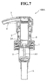
- FIG. 7 shows a push-type dispenser 100 A employing an First/F valve of a different structure
- the First/F valve A 1 is structured to have a valve disc corresponding to a sealing valve seat of the piston section 3 .
- piston section 3 is divided into separate parts one of which is a part including the sealing valve seat.
- nozzle head section 4 is covered with a nozzle head cover 7 .
- a push-type dispenser of the present invention is suitably used as a device for ejecting a liquid from inside a container by moving up and down a nozzle head.
- the push-type dispenser of the present invention is simple in structure and yet capable of surely preventing liquid leakage even when it topples over.
Landscapes
- Closures For Containers (AREA)
- Reciprocating Pumps (AREA)
- Containers And Packaging Bodies Having A Special Means To Remove Contents (AREA)
Applications Claiming Priority (3)
| Application Number | Priority Date | Filing Date | Title |
|---|---|---|---|
| JP2013-100807 | 2013-05-12 | ||
| JP2013100807 | 2013-05-12 | ||
| PCT/JP2014/063137 WO2014185541A1 (ja) | 2013-05-12 | 2014-05-12 | プッシュタイプディスペンサー |
Publications (2)
| Publication Number | Publication Date |
|---|---|
| US20160082456A1 US20160082456A1 (en) | 2016-03-24 |
| US9757753B2 true US9757753B2 (en) | 2017-09-12 |
Family
ID=51898512
Family Applications (1)
| Application Number | Title | Priority Date | Filing Date |
|---|---|---|---|
| US14/890,382 Active US9757753B2 (en) | 2013-05-12 | 2014-05-12 | Push-type dispenser |
Country Status (4)
| Country | Link |
|---|---|
| US (1) | US9757753B2 (ja) |
| JP (1) | JP6397401B2 (ja) |
| CN (1) | CN105307948B (ja) |
| WO (1) | WO2014185541A1 (ja) |
Families Citing this family (13)
| Publication number | Priority date | Publication date | Assignee | Title |
|---|---|---|---|---|
| MX2018007476A (es) * | 2016-01-13 | 2018-08-01 | Gen Cable Technologies Corp | Sistema y metodo para la aplicacion de un recubrimiento en conductores de transmision de energia electrica aereos utilizando un vehiculo aereo no tripulado. |
| KR101717972B1 (ko) * | 2016-04-26 | 2017-03-20 | (주)연우 | 파우더 토출 용기 |
| JP2019511433A (ja) * | 2016-06-02 | 2019-04-25 | 江蘇徳晋塑料包装有限公司 | 定量加圧式スプレーヘッド、及び定量加圧式スプレーヘッドを有する容器 |
| CN107892102A (zh) * | 2017-12-22 | 2018-04-10 | 余姚晟祺塑业有限公司 | 一种喷头结构 |
| JP6893745B2 (ja) * | 2017-12-28 | 2021-06-23 | 株式会社吉野工業所 | フォーマーディスペンサー |
| DE102019132343A1 (de) * | 2019-01-29 | 2020-07-30 | Rpc Bramlage Gmbh | Spender zur Ausgabe von fließfähigen, beispielsweise flüssigen oder pastösen Massen |
| KR102116648B1 (ko) * | 2020-01-22 | 2020-05-28 | 강민구 | 펌프 용기 |
| JPWO2022085103A1 (ja) * | 2020-10-21 | 2022-04-28 | ||
| CN114537879B (zh) * | 2020-11-26 | 2024-06-21 | 丁要武 | 按压式液体泵 |
| KR102424147B1 (ko) * | 2021-11-10 | 2022-07-22 | 주식회사 태성산업 | 펌핑식 용기용 스프링 및 이를 포함하는 펌핑식 용기 |
| JP7454902B2 (ja) * | 2022-02-01 | 2024-03-25 | 株式会社三谷バルブ | スプリング、それを用いたポンプ、および、噴出容器 |
| WO2024010307A1 (ko) * | 2022-07-04 | 2024-01-11 | 강성일 | 펌프 용기의 스프링 |
| KR20240106331A (ko) * | 2022-12-29 | 2024-07-08 | 주식회사 태성산업 | 펌핑식 용기용 스프링 및 이를 포함하는 펌핑식 용기 |
Citations (24)
| Publication number | Priority date | Publication date | Assignee | Title |
|---|---|---|---|---|
| US3102489A (en) * | 1961-04-11 | 1963-09-03 | Drackett Co | Dispensing pump valve structure |
| US5016783A (en) * | 1988-04-26 | 1991-05-21 | Anchor Hocking Corporation | Pump dispenser package |
| US5090601A (en) * | 1987-07-27 | 1992-02-25 | Zeller Plastik Gmbh | Container closure with a retractable turnspout |
| JPH0531410A (ja) | 1991-07-31 | 1993-02-09 | Tetsuya Tada | プツシユタイプデイスペンサ−および一次弁 |
| JPH0585581A (ja) | 1990-06-15 | 1993-04-06 | Canyon Corp | 容器とプツシユタイプの手動式デイスペンサ−との組合せ |
| JPH07144159A (ja) | 1993-01-21 | 1995-06-06 | Canyon Corp | プッシュタイプディスペンサ− |
| JPH0871462A (ja) | 1994-08-31 | 1996-03-19 | Canyon Corp | プッシュタイプディスペンサー |
| JPH0884944A (ja) | 1994-09-16 | 1996-04-02 | Canyon Corp | プッシュタイプディスペンサ− |
| JPH08182944A (ja) | 1994-12-28 | 1996-07-16 | Canyon Corp | プッシュタイプディスペンサー |
| US5582315A (en) * | 1994-08-30 | 1996-12-10 | Innovative Molding, Inc. | Pour spout closure with handle |
| US5617976A (en) * | 1995-03-21 | 1997-04-08 | L'oreal | Dispenser of liquid or pasty product which can be used especially in cosmetics |
| JPH09290185A (ja) | 1995-12-15 | 1997-11-11 | Canyon Corp | プッシュタイプディスペンサ− |
| JPH09303453A (ja) | 1996-05-10 | 1997-11-25 | Kyoritsu Kogyo Kk | 樹脂製コイルバネ及び手押しポンプ機構 |
| JPH10235241A (ja) | 1997-02-26 | 1998-09-08 | Canyon Corp | プッシュタイプディスペンサー |
| US6405904B1 (en) * | 1999-03-02 | 2002-06-18 | L'oreal, S.A. | Dispensing head including an outlet |
| US6422425B1 (en) * | 1999-12-13 | 2002-07-23 | Canyon Co., Ltd. | Liquid discharging apparatus |
| JP2002273277A (ja) | 2001-03-15 | 2002-09-24 | Canyon Corp | プッシュタイプディスペンサー |
| US20030057235A1 (en) * | 2001-09-04 | 2003-03-27 | Gueret Jean-Louis H. | Device for dispensing a product |
| US6612556B2 (en) * | 2001-04-30 | 2003-09-02 | Cornell Research Foundation, Inc. | Multihelical composite spring |
| US6729505B2 (en) * | 2000-05-11 | 2004-05-04 | Crown Cork & Seal Technologies Corporation | Dispensing pump |
| US20050184094A1 (en) * | 2004-02-19 | 2005-08-25 | Lluis Costa | Anti-clog discharge spout |
| US6976611B2 (en) * | 2000-11-27 | 2005-12-20 | Jung Min Lee | Pressure dispensing cap for liquid container |
| US20080029550A1 (en) | 2006-08-03 | 2008-02-07 | Meadwestvaco Calmar S.P.A. | Closable dispensing pump for fluid substances withdrawable from a container |
| JP2009208830A (ja) | 2008-03-06 | 2009-09-17 | Canyon Corp | ポンプディスペンサ |
Family Cites Families (4)
| Publication number | Priority date | Publication date | Assignee | Title |
|---|---|---|---|---|
| JPH0786024B2 (ja) * | 1991-12-17 | 1995-09-20 | 誠一 北林 | 泡用ポンプ |
| CN102083545B (zh) * | 2008-01-09 | 2013-11-06 | 米德韦斯特瓦科卡尔玛公司 | 旋转喷洒器及其使用方法 |
| CN201737321U (zh) * | 2010-04-21 | 2011-02-09 | 三谷精密科技(苏州)有限公司 | 喷射泵和具有该喷射泵的容器 |
| CN202089179U (zh) * | 2010-12-21 | 2011-12-28 | 杰夫·朱 | 折叠式单臂变速自行车 |
-
2014
- 2014-05-12 CN CN201480034990.9A patent/CN105307948B/zh active Active
- 2014-05-12 WO PCT/JP2014/063137 patent/WO2014185541A1/ja active Application Filing
- 2014-05-12 US US14/890,382 patent/US9757753B2/en active Active
- 2014-05-12 JP JP2015517152A patent/JP6397401B2/ja active Active
Patent Citations (25)
| Publication number | Priority date | Publication date | Assignee | Title |
|---|---|---|---|---|
| US3102489A (en) * | 1961-04-11 | 1963-09-03 | Drackett Co | Dispensing pump valve structure |
| US5090601A (en) * | 1987-07-27 | 1992-02-25 | Zeller Plastik Gmbh | Container closure with a retractable turnspout |
| US5016783A (en) * | 1988-04-26 | 1991-05-21 | Anchor Hocking Corporation | Pump dispenser package |
| JPH0585581A (ja) | 1990-06-15 | 1993-04-06 | Canyon Corp | 容器とプツシユタイプの手動式デイスペンサ−との組合せ |
| JPH0531410A (ja) | 1991-07-31 | 1993-02-09 | Tetsuya Tada | プツシユタイプデイスペンサ−および一次弁 |
| JPH07144159A (ja) | 1993-01-21 | 1995-06-06 | Canyon Corp | プッシュタイプディスペンサ− |
| US5582315A (en) * | 1994-08-30 | 1996-12-10 | Innovative Molding, Inc. | Pour spout closure with handle |
| JPH0871462A (ja) | 1994-08-31 | 1996-03-19 | Canyon Corp | プッシュタイプディスペンサー |
| JPH0884944A (ja) | 1994-09-16 | 1996-04-02 | Canyon Corp | プッシュタイプディスペンサ− |
| JPH08182944A (ja) | 1994-12-28 | 1996-07-16 | Canyon Corp | プッシュタイプディスペンサー |
| US5617976A (en) * | 1995-03-21 | 1997-04-08 | L'oreal | Dispenser of liquid or pasty product which can be used especially in cosmetics |
| JPH09290185A (ja) | 1995-12-15 | 1997-11-11 | Canyon Corp | プッシュタイプディスペンサ− |
| JPH09303453A (ja) | 1996-05-10 | 1997-11-25 | Kyoritsu Kogyo Kk | 樹脂製コイルバネ及び手押しポンプ機構 |
| JPH10235241A (ja) | 1997-02-26 | 1998-09-08 | Canyon Corp | プッシュタイプディスペンサー |
| US6405904B1 (en) * | 1999-03-02 | 2002-06-18 | L'oreal, S.A. | Dispensing head including an outlet |
| US6422425B1 (en) * | 1999-12-13 | 2002-07-23 | Canyon Co., Ltd. | Liquid discharging apparatus |
| US6729505B2 (en) * | 2000-05-11 | 2004-05-04 | Crown Cork & Seal Technologies Corporation | Dispensing pump |
| US6976611B2 (en) * | 2000-11-27 | 2005-12-20 | Jung Min Lee | Pressure dispensing cap for liquid container |
| JP2002273277A (ja) | 2001-03-15 | 2002-09-24 | Canyon Corp | プッシュタイプディスペンサー |
| US6612556B2 (en) * | 2001-04-30 | 2003-09-02 | Cornell Research Foundation, Inc. | Multihelical composite spring |
| US20030057235A1 (en) * | 2001-09-04 | 2003-03-27 | Gueret Jean-Louis H. | Device for dispensing a product |
| JP2003104468A (ja) | 2001-09-04 | 2003-04-09 | L'oreal Sa | 流体の分与装置 |
| US20050184094A1 (en) * | 2004-02-19 | 2005-08-25 | Lluis Costa | Anti-clog discharge spout |
| US20080029550A1 (en) | 2006-08-03 | 2008-02-07 | Meadwestvaco Calmar S.P.A. | Closable dispensing pump for fluid substances withdrawable from a container |
| JP2009208830A (ja) | 2008-03-06 | 2009-09-17 | Canyon Corp | ポンプディスペンサ |
Non-Patent Citations (1)
| Title |
|---|
| English translation of International Search Report of PCT/JP2014/063137. |
Also Published As
| Publication number | Publication date |
|---|---|
| CN105307948A (zh) | 2016-02-03 |
| US20160082456A1 (en) | 2016-03-24 |
| JP6397401B2 (ja) | 2018-09-26 |
| WO2014185541A1 (ja) | 2014-11-20 |
| CN105307948B (zh) | 2017-10-20 |
| JPWO2014185541A1 (ja) | 2017-02-23 |
Similar Documents
| Publication | Publication Date | Title |
|---|---|---|
| US9757753B2 (en) | Push-type dispenser | |
| JP6057597B2 (ja) | 蓄圧式トリガースプレイヤー及びその蓄圧バルブ | |
| WO2016202303A1 (zh) | 雾化器及其气溶胶发生装置 | |
| US4572410A (en) | Safety actuator for an aerosol valve | |
| US9315314B2 (en) | Dual actuated aerosol devices | |
| JP2005193234A (ja) | ロック可能な分配ヘッド | |
| US10307778B2 (en) | Trigger-type liquid dispenser | |
| WO2017188035A1 (ja) | トリガースプレイヤ | |
| US9708093B2 (en) | Dispensing closure for powdered products | |
| US20170107045A1 (en) | Device for delivering a pellet | |
| WO2013123123A1 (en) | Auto-refill single dose dispenser | |
| EP2228319B1 (en) | Aerosol cap with lock | |
| JP2011245435A (ja) | トリガースプレイヤー | |
| JP2013056697A (ja) | 蓄圧式トリガースプレイヤー及びその蓄圧バルブ | |
| WO2014115838A1 (ja) | 吐出器 | |
| WO2019202882A1 (ja) | 定量噴射ユニット | |
| JP6679288B2 (ja) | 内容物放出機構およびこの内容物放出機構を備えたエアゾール式製品 | |
| JP2013212677A (ja) | 塗布液カートリッジ | |
| JP2004113993A (ja) | エアゾール製品 | |
| KR20130004804U (ko) | 텀블러 뚜껑 | |
| JP6353728B2 (ja) | エアゾール容器の常時一定方向ワイド噴射ノズル | |
| JP6913530B2 (ja) | 粉体供給機構 | |
| WO2019163183A1 (ja) | エアゾール容器用アクチュエータ | |
| JP2012101801A (ja) | 倒立用ポンプディスペンサー | |
| JP2022077217A (ja) | 吐出具 |
Legal Events
| Date | Code | Title | Description |
|---|---|---|---|
| AS | Assignment |
Owner name: CANYON CORPORATION, JAPAN Free format text: ASSIGNMENT OF ASSIGNORS INTEREST;ASSIGNOR:MIEKO TADA, REPRESENTATIVE FOR DECEASED INVENTOR, TETSUYA TADA;REEL/FRAME:037023/0821 Effective date: 20151030 |
|
| STCF | Information on status: patent grant |
Free format text: PATENTED CASE |
|
| MAFP | Maintenance fee payment |
Free format text: PAYMENT OF MAINTENANCE FEE, 4TH YR, SMALL ENTITY (ORIGINAL EVENT CODE: M2551); ENTITY STATUS OF PATENT OWNER: SMALL ENTITY Year of fee payment: 4 |