US9528541B2 - Holder for casting into a concrete element - Google Patents
Holder for casting into a concrete element Download PDFInfo
- Publication number
- US9528541B2 US9528541B2 US14/351,081 US201214351081A US9528541B2 US 9528541 B2 US9528541 B2 US 9528541B2 US 201214351081 A US201214351081 A US 201214351081A US 9528541 B2 US9528541 B2 US 9528541B2
- Authority
- US
- United States
- Prior art keywords
- formwork
- retaining
- retaining arrangement
- clamping
- concrete element
- Prior art date
- Legal status (The legal status is an assumption and is not a legal conclusion. Google has not performed a legal analysis and makes no representation as to the accuracy of the status listed.)
- Expired - Fee Related, expires
Links
- 238000005266 casting Methods 0.000 title abstract description 6
- 238000009415 formwork Methods 0.000 claims abstract description 88
- 230000005641 tunneling Effects 0.000 claims description 4
- 238000002360 preparation method Methods 0.000 abstract description 4
- 238000010276 construction Methods 0.000 abstract description 2
- 239000000463 material Substances 0.000 description 12
- 239000004033 plastic Substances 0.000 description 8
- 229920003023 plastic Polymers 0.000 description 8
- 210000000078 claw Anatomy 0.000 description 7
- 239000007769 metal material Substances 0.000 description 7
- 238000011161 development Methods 0.000 description 5
- XEEYBQQBJWHFJM-UHFFFAOYSA-N Iron Chemical compound [Fe] XEEYBQQBJWHFJM-UHFFFAOYSA-N 0.000 description 4
- 238000013461 design Methods 0.000 description 4
- 238000001746 injection moulding Methods 0.000 description 4
- 238000003780 insertion Methods 0.000 description 4
- 230000037431 insertion Effects 0.000 description 4
- 230000000717 retained effect Effects 0.000 description 4
- 239000000853 adhesive Substances 0.000 description 3
- 230000001070 adhesive effect Effects 0.000 description 3
- 238000004519 manufacturing process Methods 0.000 description 3
- 238000000034 method Methods 0.000 description 3
- 239000013013 elastic material Substances 0.000 description 2
- 229910052742 iron Inorganic materials 0.000 description 2
- 230000000149 penetrating effect Effects 0.000 description 2
- 238000003825 pressing Methods 0.000 description 2
- 238000007789 sealing Methods 0.000 description 2
- 239000004952 Polyamide Substances 0.000 description 1
- 239000004698 Polyethylene Substances 0.000 description 1
- 229910000831 Steel Inorganic materials 0.000 description 1
- 239000004708 Very-low-density polyethylene Substances 0.000 description 1
- 239000004676 acrylonitrile butadiene styrene Substances 0.000 description 1
- 229910052782 aluminium Inorganic materials 0.000 description 1
- XAGFODPZIPBFFR-UHFFFAOYSA-N aluminium Chemical compound [Al] XAGFODPZIPBFFR-UHFFFAOYSA-N 0.000 description 1
- 238000005253 cladding Methods 0.000 description 1
- 238000001125 extrusion Methods 0.000 description 1
- 238000009434 installation Methods 0.000 description 1
- 230000003993 interaction Effects 0.000 description 1
- 229910052751 metal Inorganic materials 0.000 description 1
- 239000002184 metal Substances 0.000 description 1
- 229920002647 polyamide Polymers 0.000 description 1
- 239000004417 polycarbonate Substances 0.000 description 1
- 229920000515 polycarbonate Polymers 0.000 description 1
- 239000004800 polyvinyl chloride Substances 0.000 description 1
- 238000012545 processing Methods 0.000 description 1
- 230000001681 protective effect Effects 0.000 description 1
- 239000007787 solid Substances 0.000 description 1
- 239000010959 steel Substances 0.000 description 1
- 229920001866 very low density polyethylene Polymers 0.000 description 1
- 239000002023 wood Substances 0.000 description 1
Images




Classifications
-
- F—MECHANICAL ENGINEERING; LIGHTING; HEATING; WEAPONS; BLASTING
- F16—ENGINEERING ELEMENTS AND UNITS; GENERAL MEASURES FOR PRODUCING AND MAINTAINING EFFECTIVE FUNCTIONING OF MACHINES OR INSTALLATIONS; THERMAL INSULATION IN GENERAL
- F16B—DEVICES FOR FASTENING OR SECURING CONSTRUCTIONAL ELEMENTS OR MACHINE PARTS TOGETHER, e.g. NAILS, BOLTS, CIRCLIPS, CLAMPS, CLIPS OR WEDGES; JOINTS OR JOINTING
- F16B19/00—Bolts without screw-thread; Pins, including deformable elements; Rivets
-
- E—FIXED CONSTRUCTIONS
- E04—BUILDING
- E04B—GENERAL BUILDING CONSTRUCTIONS; WALLS, e.g. PARTITIONS; ROOFS; FLOORS; CEILINGS; INSULATION OR OTHER PROTECTION OF BUILDINGS
- E04B1/00—Constructions in general; Structures which are not restricted either to walls, e.g. partitions, or floors or ceilings or roofs
- E04B1/38—Connections for building structures in general
- E04B1/41—Connecting devices specially adapted for embedding in concrete or masonry
-
- E—FIXED CONSTRUCTIONS
- E21—EARTH OR ROCK DRILLING; MINING
- E21D—SHAFTS; TUNNELS; GALLERIES; LARGE UNDERGROUND CHAMBERS
- E21D11/00—Lining tunnels, galleries or other underground cavities, e.g. large underground chambers; Linings therefor; Making such linings in situ, e.g. by assembling
- E21D11/04—Lining with building materials
- E21D11/08—Lining with building materials with preformed concrete slabs
- E21D11/086—Methods of making concrete lining segments
-
- E—FIXED CONSTRUCTIONS
- E21—EARTH OR ROCK DRILLING; MINING
- E21D—SHAFTS; TUNNELS; GALLERIES; LARGE UNDERGROUND CHAMBERS
- E21D11/00—Lining tunnels, galleries or other underground cavities, e.g. large underground chambers; Linings therefor; Making such linings in situ, e.g. by assembling
- E21D11/04—Lining with building materials
- E21D11/10—Lining with building materials with concrete cast in situ; Shuttering also lost shutterings, e.g. made of blocks, of metal plates or other equipment adapted therefor
-
- E—FIXED CONSTRUCTIONS
- E21—EARTH OR ROCK DRILLING; MINING
- E21D—SHAFTS; TUNNELS; GALLERIES; LARGE UNDERGROUND CHAMBERS
- E21D11/00—Lining tunnels, galleries or other underground cavities, e.g. large underground chambers; Linings therefor; Making such linings in situ, e.g. by assembling
- E21D11/38—Waterproofing; Heat insulating; Soundproofing; Electric insulating
- E21D11/383—Waterproofing; Heat insulating; Soundproofing; Electric insulating by applying waterproof flexible sheets; Means for fixing the sheets to the tunnel or cavity wall
-
- E—FIXED CONSTRUCTIONS
- E04—BUILDING
- E04B—GENERAL BUILDING CONSTRUCTIONS; WALLS, e.g. PARTITIONS; ROOFS; FLOORS; CEILINGS; INSULATION OR OTHER PROTECTION OF BUILDINGS
- E04B1/00—Constructions in general; Structures which are not restricted either to walls, e.g. partitions, or floors or ceilings or roofs
- E04B1/38—Connections for building structures in general
- E04B1/41—Connecting devices specially adapted for embedding in concrete or masonry
- E04B1/4114—Elements with sockets
-
- Y—GENERAL TAGGING OF NEW TECHNOLOGICAL DEVELOPMENTS; GENERAL TAGGING OF CROSS-SECTIONAL TECHNOLOGIES SPANNING OVER SEVERAL SECTIONS OF THE IPC; TECHNICAL SUBJECTS COVERED BY FORMER USPC CROSS-REFERENCE ART COLLECTIONS [XRACs] AND DIGESTS
- Y10—TECHNICAL SUBJECTS COVERED BY FORMER USPC
- Y10T—TECHNICAL SUBJECTS COVERED BY FORMER US CLASSIFICATION
- Y10T29/00—Metal working
- Y10T29/49—Method of mechanical manufacture
- Y10T29/49826—Assembling or joining
- Y10T29/49947—Assembling or joining by applying separate fastener
- Y10T29/49948—Multipart cooperating fastener [e.g., bolt and nut]
Definitions
- Such a retaining arrangement is known from DE 39 31 369 C2.
- This retaining arrangement has a plug-in opening or a screw-in opening for a corresponding round cap.
- the retaining arrangement is positioned on a formwork in a manner which is not known and encased in concrete. Once the formwork has been removed, a round cap is fastened on the retaining arrangement and a lining is fastened on the round cap in a suitable manner, for example is welded thereto.
- a further retaining arrangement is known from DE 198 47 360 C1.
- This retaining arrangement is designed in the form of a threaded sleeve which is cast into a concrete element in the region of a depression incorporated in the concrete element.
- a lining is then formed in the depression and a hole is made in the lining in the region of the threaded sleeve.
- a tie bolt is screwed into the threaded sleeve, through said hole, in order to fasten the lining on the concrete element.
- a round cap welded or adhesively bonded to the lining, is fitted in the region of the tie bolt.
- the retaining arrangement according to the invention provides a fastening device with which the retaining arrangement can be secured straightforwardly and reliably on the formwork at the preparation stage of the concreting operation. It is also the case that the retaining arrangement secured in this way is retained reliably on the formwork during the concreting operation, wherein, following the concreting operation, the formwork can be readily removed from the concrete element and the retaining arrangement, which is now cast into the concrete element.
- the fastening device has a retaining part, which interacts with the formwork, and a clamping element, which is arranged on the outer surface of the retaining arrangement, wherein the clamping element interacts with the retaining part.
- the fastening device designed in this way is easy to handle.
- the clamping element is designed in the form of an undercut which is incorporated in the retaining body and by means of which the clamping element is clamped onto the retaining part fastened on the formwork.
- the retaining part is a magnet which is positioned, preferably together with the retaining body, on the formwork, which is produced from an iron material. During the formwork-removal operation, the retaining body is then released from the formwork together with the magnet, and the magnet can be removed from the retaining body for further use. If, in contrast, the magnet remains on the formwork during the formwork-removal operation, it can be removed from the formwork or else a new retaining body is fastened on the magnet for the next concreting operation.
- the retaining part is a formwork protuberance, and the formwork protuberance can be fastened on the formwork by means of a retaining pin.
- a central opening is preferably made here in the formwork protuberance, and the retaining pin can be guided through this opening.
- the retaining pin like the formwork protuberance as well, is produced preferably from a metallic material and, for example in the case of a formwork produced from wood, can be driven straightforwardly into the same. It is also conceivable, however, for the retaining pin produced from a metallic material to be driven into a formwork produced from metal. It is also possible, within the context of the invention, for the retaining pin to be formed in one piece with the formwork protuberance, wherein the structural unit prefabricated in this way is then installed on the formwork.
- a further embodiment of the invention provides for the formwork protuberance to be adhesively bonded or welded to the formwork.
- An adhesively bonded formwork protuberance can be released from the formwork again for repositioning purposes, whereas a formwork protuberance produced from a metallic material and welded to a formwork which is likewise produced from a metallic material remains on the formwork preferably on a permanent basis.
- a new retaining arrangement is then plugged onto the formwork protuberance.
- the retaining protuberance can be covered by a cap so as not to be contaminated by concrete. If it is not covered when not in use, any adhering concrete can be straightforwardly removed, for example, using a high-pressure cleaner. If the formwork protuberance is no longer required, it can be removed from the formwork using a severing tool.
- the retaining part may be designed in the form of a piston which is inserted in a movable manner in a cylinder incorporated in the formwork.
- the piston is extended, for example hydraulically or pneumatically, out of the formwork to the extent where the clamping element of the retaining arrangement can be fastened on the piston.
- the piston can then be retracted all the way into the cylinder in the formwork in order to form a smooth formwork surface.
- the fastening device is a suction cup which interacts with the retaining arrangement.
- the retaining arrangement here is preferably designed such that it forms the suction cup at the same time.
- the retaining arrangement it is possible for the retaining arrangement to be produced from a rubber-like material and thus to be fastened straightforwardly on the clean surface of the formwork.
- the retaining arrangement has a mushroom-shaped basic body and a hollow clamping body, which interacts with the basic body. This at least two-part construction of the retaining arrangement renders straightforward production possible.
- the basic body and the hollow clamping body here are preferably produced from a plastics material using injection molding.
- the hollow clamping body is designed in the form of a carrier, which forms a cavity and has at least one clamping bracket, preferably two clamping brackets, arranged in the cavity of the carrier.
- the carrier is, for example, of cylindrical or rectangular design and is inserted into a corresponding recess or into the interior of the basic body.
- the carrier is produced, together with the clamping brackets, as a single component, for example using plastics injection molding.
- the carrier it is possible for the carrier to be covered, on the concrete-facing outer side, by a separately produced covering cap, wherein the covering cap prevents concrete from penetrating into the cavity or into the interior.
- two clamping brackets are formed in one piece with a base plate of the hollow clamping body and the clamping brackets can be pivoted in relation to the base plate.
- the hollow clamping body produced in this way can be installed in a straightforward manner by the clamping brackets being pivoted to form the cavity of the hollow clamping body and then by the hollow clamping body formed in this way subsequently being inserted, at least in part, into a, for example, rectangular or cylindrical recess or into the interior of the mushroom-shaped basic body. It is possible here for the hollow clamping body and the basic body to be adhesively bonded or clamped to one another in addition.
- the base plate projects laterally beyond the cylindrical recess and thus ensures a firm hold in the concrete.
- a holder can be inserted into the cavity through the outer surface.
- the holder is an anchor which interacts with a round cap.
- the anchor may be produced in one piece with the round cap for example from a plastics material.
- the outer surface has an outer region forming the clamping element and an inner region forming a formwork-facing covering of the cavity. The anchor is driven through the inner region of the outer surface and introduced into the cavity for clamping to the clamping brackets.
- a concrete element is provided for use in tunneling or engineering, wherein the concrete element is cast using at least one formwork, wherein a retaining arrangement as claimed in one of the preceding claims is fastened in a releasable manner on the formwork element prior to the concreting operation.
- a method of fastening a lining on the surface of a concrete element provides the following steps:
- the lining prefferably be adhesively bonded or welded to the round cap in a conventional manner. It is preferable, however, for the round cap to be provided with a claw-type fastening which, during the operation of fastening the lining on the round cap, penetrates into a nonwoven layer applied to that side of the lining which is facing the concrete element.
- the round cap here is of multi-part design with at least one base part and a cover, such that, during an operation of pressing the lining onto the round cap, claws extend, with position-altering action, through recesses in the cover of the round cap and penetrate into the nonwoven layer. In order to prevent the connection from releasing, it is provided that the cover and the base part are locked to one another in the pressed-on end position.
- the components are produced from a plastics material, for example PVC, ABS, PE, VLDPE, TPO, FPO, polyamide or polycarbonate.
- a plastics material for example PVC, ABS, PE, VLDPE, TPO, FPO, polyamide or polycarbonate.
- ABS in particular is impact-resistant and, in addition, lends itself well to processing.
- the components in particular, the claws, to be produced from metallic material such as steel or aluminum.
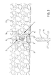
- FIG. 1 shows a cross section through a retaining arrangement according to the invention which is cast into concrete and is fastened on a formwork
- FIG. 2 shows a further cross section through a retaining arrangement according to FIG. 1 , which is cast into concrete and has an anchor for insertion into a cavity of the retaining arrangement,
- FIG. 3 shows a cross section through a second exemplary embodiment of a retaining arrangement which is cast into concrete and is fastened on a formwork
- FIG. 4 shows a cross section according to FIG. 3 , with the formwork removed and with an anchor for insertion into a cavity of the retaining arrangement
- FIG. 5 shows a cross section through a third exemplary embodiment of a retaining arrangement which is cast into concrete and is fastened on a formwork
- FIG. 6 shows a side view of a further exemplary embodiment of a retaining arrangement
- FIG. 6 a shows a sectional illustration of FIG. 6
- FIG. 6 b shows a plan view of FIG. 6
- FIG. 6 c shows a sectional illustration of an exemplary embodiment of a retaining arrangement which has been modified in relation to FIG. 6 a
- FIG. 7 shows a side view of a further exemplary embodiment of a retaining arrangement
- FIG. 7 a shows a sectional illustration of FIG. 7
- FIG. 7 b shows a plan view of FIG. 7 .
- FIG. 1 illustrates a first cross section of a retaining arrangement 1 configured according to a first embodiment.
- the retaining arrangement 1 has a mushroom-shaped basic body 2 and a hollow clamping body 3 , which interacts with the basic body 2 .
- the retaining arrangement 1 is fastened on a formwork protuberance 5 via a clamping element designed in the form of an undercut 4 , wherein the formwork protuberance 5 is fastened on, in particular welded to, a formwork 6 .
- the formwork protuberance 5 and the clamping element designed in the form of an undercut 4 form a fastening device for fastening the retaining arrangement 1 on the formwork 6 .
- the retaining arrangement 1 has an outer surface 7 which is aligned with the formwork 6 and has an outer region forming the clamping element and an inner region forming a formwork-facing covering of an interior 8 of the retaining arrangement 1 .
- the hollow clamping body 3 is inserted into the interior 8 , said hollow clamping body comprising a base plate 10 and two clamping brackets 9 , which are produced in one piece with a base plate 10 , for example in the form of a plastics injection molding.
- the clamping brackets 9 In the installed state illustrated, the clamping brackets 9 have been pivoted in relation to the base plate 10 to form a cavity 11 , said clamping brackets being produced in a swung-up state (not illustrated).
- the clamping brackets 9 have barbs 12 , which interact with the corresponding profiling 13 of a holder ( FIG. 2 ) designed in the form of an anchor 14 , when the anchor 14 is introduced or pushed into the cavity 11 by way of the shank part which bears the profiling 13 .
- the anchor 14 here pierces the inner region of the outer surface 7 by way of the tip of the shank part and, as the pushing-in movement continues, is introduced into the cavity 11 in order for the profiling 13 to be clamped to the barbs 12 .
- the formwork 6 is configured, for example, in the form of tunneling segments produced from a metal material, in particular iron.
- the anchor 14 ( FIG. 2 ) is used to fasten a round cap on the retaining arrangement 1 cast into the concrete element 15 .
- the anchor 14 ( FIG. 2 ) is used to fasten a round cap on the retaining arrangement 1 cast into the concrete element 15 .
- any desired number of retaining arrangements 1 according to the invention, to be fastened on the formwork 6 and then cast into the concrete element 15 .
- a lining for example in the form of a sheet material, is fastened on the round cap, or the round caps, in particular for sealing purposes.
- This fastening operation can take place in any desired manner.
- the sheet material to be adhesively bonded to the round cap using a suitable adhesive, wherein the adhesive is applied to the round cap or an adhesive pad is attached to the round cap.
- the sheet material, provided with a nonwoven layer can be fastened by means of a hook-and-loop fastener which has been fastened on the round cap or applied thereto in some other manner (extrusion Velcro).
- the round cap it is also possible, however, for the round cap to be provided with a claw-type fastening device, in which case, during the operation of fastening the lining, the claws then penetrate into a nonwoven layer of the sheet material, which has been laminated with such a nonwoven layer.
- the round cap here has a base plate, with which a cover interacts.
- the cover has a defined extent of its outer periphery positioned on the outer circumference of the base plate.
- This basic position is secured temporarily, for example, by one (encircling) or more groove/tongue connection(s).
- the claws are retained in defined positions by the appropriate configuration of those surfaces of the base plate and of the cover which are facing the interior.
- the claws each having grippers and a pivoting mechanism, are arranged virtually entirely within the interior, whereas, in the retaining position, the claws have their grippers projecting, at least to a large extent, out of the cover, while the pivoting mechanism remains entirely in the interior.
- the pivoting mechanism interacts with the corresponding surfaces of the base plate and of the cover such that, during the operation of pressing the cover onto the base plate, the pivoting mechanism pivots the grippers, which extend here through openings in the form of slots in the cover.
- the claws, or the grippers thereof penetrate reliably into the nonwoven layer without the latter being displaced in any way.
- the cover In the retaining position, they are engaged in the nonwoven layer such that it is no longer possible for the nonwoven layer to be released even under, for example, tensile loading.
- the cover In the retaining position, the cover is secured to or locked with the base plate on a permanent basis (in contrast to the basic position) by means of, for example, a groove/tongue connection.
- FIG. 2 shows a cross section through the retaining arrangement 1 according to FIG. 1 which is cast into concrete and has the anchor 14 arranged beneath it for insertion into the cavity 11 of the retaining arrangement 1 , this cross section being rotated by 90°.
- the base plate 10 of the hollow clamping body 3 has two arms extending laterally beyond the basic body 2 and is thus anchored in the concrete element 15 in a state in which it is encased by concrete.
- clamping brackets 9 in the formwork-facing end region, have been bent up in relation to the interior 8 of the basic body 2 and, in addition, can engage in a groove of the basic body 2 , this ensures solid, non-separable interaction of the hollow clamping body 3 and of the basic body 2 in the concrete element 15 .
- FIG. 3 shows a cross section through a second exemplary embodiment of a retaining arrangement 1 a which is cast into a concrete element and is fastened on the formwork 6 .
- the formwork protuberance 5 a is designed to be somewhat higher than in the first exemplary embodiment.
- the hollow clamping body 3 a has a carrier 16 , two clamping brackets 9 a being incorporated in the carrier 16 .
- the clamping brackets 9 a are formed, as illustrated, in the manner of a cable tie element with barbs 12 a , and the clamping brackets 9 a are produced in one piece with the carrier 16 .
- the carrier 16 is, for example, of cylindrical or rectangular design and is inserted into the interior 8 a of the basic body 2 a and secured in the basic body 2 a , possibly in addition, by a groove/tongue connection.
- the carrier 16 is produced, together with the clamping brackets 9 a , as a single component, for example using plastics injection molding.
- the carrier 16 is covered, on the concrete-facing outer side, by a separately produced covering cap 17 , wherein the covering cap 17 prevents concrete from penetrating into the cavity 11 a.
- FIG. 4 shows the same cross section through the retaining arrangement 1 a according to FIG. 3 , albeit with the formwork 6 removed and with an anchor 14 a which is arranged beneath the retaining arrangement 1 a and has a profiling 13 a for insertion into the cavity 12 a of the retaining arrangement 1 a.
- FIG. 5 shows a cross section through a third exemplary embodiment of a retaining arrangement 1 b which is cast into concrete and is fastened on a formwork 6 .
- the formwork protuberance 5 b is designed to be flat and the outer surface 7 b of the basic body 2 b is adapted correspondingly.
- the hollow clamping body 3 b is formed in the manner illustrated and has an annular shoulder 18 , the profiling of an anchor clamping itself thereon.
- the anchor it is also possible for the anchor to have a spring-deflection undercut which secures itself on the annular shoulder 18 once the anchor has been pushed in.
- the cavity 11 of the hollow clamping body 9 b is covered by a covering cap 17 a on the side of the concrete element 15 .
- FIG. 6 shows a further exemplary embodiment of a retaining arrangement 1 c .
- the basic body 2 c is produced, for example, from a metallic material and is connected to a foot part 20 , which constitutes the clamping element having the undercut 4 , and by way of which the basic body 2 c is fastened on a formwork protuberance 5 , 5 a , 5 b (not illustrated here).
- the foot part 20 is produced from an elastic material, for example rubber or also from an elastic plastics material, and is fixed to the basic body 2 c .
- the basic body 2 c is designed in the form of part of a cone and has end flattened portions 19 , which ensures that, in the event of the retaining arrangement 1 c cast into concrete being subjected to a rotary movement, said retaining arrangement 1 c is retained in captive fashion in the concrete.
- the basic body 2 c has a recess, for example in the form of a bore, in which a thread 21 is made.
- a screw forming a holder, can be screwed into said thread 21 and can be used to fasten, for example, a round cap or some other carrier component on the retaining arrangement 1 c.
- FIG. 6 b shows a plan view of the retaining arrangement 1 c , the flattened portions 19 at one end being clearly visible.
- FIG. 6 d is modified slightly in relation to the exemplary embodiment which is illustrated in FIGS. 6 to 6 c in that, here, the recess incorporated in the basic body 2 c is provided with an end cylinder portion 22 which has a larger diameter than the rest of the recess.
- An anchor 14 , 14 a which is retained in the cylinder portion 22 at one end, can be inserted into said recess.
- the exemplary embodiment of a retaining arrangement 1 d which is illustrated in FIGS. 7 to 7 b , differs from the exemplary embodiments illustrated in FIGS. 6 to 6 c in that, here, the foot part 20 a is of oval design and the undercut 4 is arranged laterally alongside the basic body 2 d . It is also the case in this exemplary embodiment that the foot part 20 a is produced from an elastic material, for example rubber or also from an elastic plastics material, and is fixed to the basic body 2 d .
- the basic body 2 d is designed to extend as far as the formwork (not illustrated here), in which case, following the concreting operation, said basic body 2 d extends as far as the surface of the concrete.
- This basic body 2 d is also provided with a thread 21 , into which a holder in the form of a screw can be screwed. During the casting operation, the threaded opening can be covered with, for example, a protective sheet material.
Landscapes
- Engineering & Computer Science (AREA)
- Structural Engineering (AREA)
- Architecture (AREA)
- Mining & Mineral Resources (AREA)
- Civil Engineering (AREA)
- General Life Sciences & Earth Sciences (AREA)
- Life Sciences & Earth Sciences (AREA)
- Geochemistry & Mineralogy (AREA)
- Geology (AREA)
- General Engineering & Computer Science (AREA)
- Mechanical Engineering (AREA)
- Physics & Mathematics (AREA)
- Electromagnetism (AREA)
- Forms Removed On Construction Sites Or Auxiliary Members Thereof (AREA)
Applications Claiming Priority (4)
| Application Number | Priority Date | Filing Date | Title |
|---|---|---|---|
| DE102011115715 | 2011-10-12 | ||
| DE102011115715.1 | 2011-10-12 | ||
| DE102011115715A DE102011115715A1 (de) | 2011-10-12 | 2011-10-12 | Halterung zum Eingießen in ein Betonelement |
| PCT/EP2012/004177 WO2013053452A2 (de) | 2011-10-12 | 2012-10-05 | Halterung zum eingiessen in ein betonelement |
Publications (2)
| Publication Number | Publication Date |
|---|---|
| US20140286726A1 US20140286726A1 (en) | 2014-09-25 |
| US9528541B2 true US9528541B2 (en) | 2016-12-27 |
Family
ID=47146307
Family Applications (1)
| Application Number | Title | Priority Date | Filing Date |
|---|---|---|---|
| US14/351,081 Expired - Fee Related US9528541B2 (en) | 2011-10-12 | 2012-10-05 | Holder for casting into a concrete element |
Country Status (5)
| Country | Link |
|---|---|
| US (1) | US9528541B2 (de) |
| EP (1) | EP2766574B1 (de) |
| CA (1) | CA2851778A1 (de) |
| DE (1) | DE102011115715A1 (de) |
| WO (1) | WO2013053452A2 (de) |
Cited By (1)
| Publication number | Priority date | Publication date | Assignee | Title |
|---|---|---|---|---|
| US20250092669A1 (en) * | 2023-09-15 | 2025-03-20 | Copper Line Partners, LLC | Attachment device for a roof nailer pane. |
Families Citing this family (13)
| Publication number | Priority date | Publication date | Assignee | Title |
|---|---|---|---|---|
| WO2013112166A2 (en) * | 2012-01-26 | 2013-08-01 | Empire Technology Development Llc | Sprung latch fastener |
| DE102013100755A1 (de) * | 2013-01-25 | 2014-07-31 | Meese GmbH | Befestigungseinrichtung |
| AT515066A1 (de) * | 2013-11-06 | 2015-05-15 | Ke Kelit Kunststoffwerk Gmbh | Verfahren zum Markieren eines Messpunkts in einer gegossenen Betondecke |
| AT515067B1 (de) * | 2013-11-06 | 2022-01-15 | Ke Kelit Gmbh | Verfahren zum Markieren eines Messpunkts in einer gegossenen Betondecke |
| JP6356441B2 (ja) * | 2014-03-07 | 2018-07-11 | 西日本高速道路株式会社 | 吊アンカー構造およびトンネル施工方法 |
| NL2012765B1 (en) | 2014-05-06 | 2016-02-23 | Trelleborg Ridderkerk B V | Method for producing a construction element, in particular a tunnel element, having a watertight seal. |
| US10781835B2 (en) | 2015-03-31 | 2020-09-22 | Tremco Incorporated | Mechanically detachable membrane for pre-applied waterproofing |
| JP6308561B2 (ja) * | 2015-06-30 | 2018-04-11 | 株式会社 協創 | 耐火被覆構造体の施工方法及びこの施工方法に用いられる耐火被覆構造体 |
| DE102017128436A1 (de) * | 2017-11-30 | 2019-06-06 | MAX BÖGL Fertigteilwerke GmbH & Co. KG | Verfahren zum Herstellen eines Tübbings sowie Tübbing |
| USD976754S1 (en) * | 2018-03-12 | 2023-01-31 | Transportation Ip Holdings, Llc | Rail vehicle traction pin |
| CN109441483B (zh) * | 2018-11-26 | 2024-02-13 | 四川蓝海智能装备制造有限公司 | 用于隧道模喷浇筑的电磁模板 |
| CN109611126B (zh) * | 2019-01-25 | 2024-05-31 | 四川蓝海智能装备制造有限公司 | 一种拱喷台车 |
| DE102022107996A1 (de) * | 2022-04-04 | 2023-10-05 | Henning Hager | Ankereinheit, Bauwerkseinrichtung und Verfahren zum Herstellen einer Bauwerkseinrichtung |
Citations (20)
| Publication number | Priority date | Publication date | Assignee | Title |
|---|---|---|---|---|
| US2135118A (en) * | 1936-04-18 | 1938-11-01 | Andrew H Stewart | Tile-mounting structure |
| US3158964A (en) * | 1962-06-29 | 1964-12-01 | Wilson E Haas | Structural connector |
| US3789776A (en) * | 1972-11-07 | 1974-02-05 | Gen Tire & Rubber Co | Hopper car hatch cover and lock assembly |
| US4631887A (en) * | 1986-01-31 | 1986-12-30 | Francovitch Thomas F | Non-penetrating roof membrane anchoring system |
| US4717301A (en) * | 1986-02-21 | 1988-01-05 | Itw Fastex Italia S.P.A. | Panel fastener supporting bush for cover panels comprising a base panel and a foam portion |
| US4726561A (en) * | 1986-09-15 | 1988-02-23 | Worzala Jr Edward | Concrete insert apparatus |
| DE3931369A1 (de) | 1989-05-30 | 1990-12-06 | Niederberg Chemie | Vorrichtung zum befestigen |
| US5104273A (en) * | 1990-04-16 | 1992-04-14 | Clark Arlance G | Wall anchor socket apparatus |
| US5240543A (en) * | 1990-06-11 | 1993-08-31 | Atr International, Inc. | Apparatus for and method of seating a fastener insert in a honeycomb panel |
| DE19847360C1 (de) | 1998-10-14 | 2000-03-02 | Steuler Industriewerke Gmbh | Verfahren zur Befestigung von großformatigen Thermoplast-Auskleidungsplatten auf aus Fertigteilen bestehenden Betonkonstruktionen |
| US6109587A (en) * | 1997-09-26 | 2000-08-29 | M.A. Industries, Inc. | Manhole lift insert locator |
| JP2001107446A (ja) | 1999-10-13 | 2001-04-17 | Kanken:Kk | コンクリート製品における接合構造 |
| DE20111550U1 (de) | 2001-07-13 | 2002-01-17 | Betomax Kunststoff- und Metallwarenfabrik GmbH & Co. KG, 41460 Neuss | Einbetonierbare Gewindehülse für Ankerstäbe |
| US6450505B1 (en) * | 1998-12-18 | 2002-09-17 | Norman W. Gavin | Seal for casting in a concrete wall of a fluid distribution system container |
| US6688049B2 (en) * | 2002-01-31 | 2004-02-10 | Bowco Industries Inc. | Hook facility for concrete structure |
| US7387288B2 (en) * | 2003-12-05 | 2008-06-17 | The Lamson & Sessions Co. | Fitting for ENT tubing |
| DE102009003726B3 (de) | 2009-04-02 | 2010-11-04 | Herold Kunststofftechnik | Betontübbing und Verfahren zur Herstellung desselben |
| JP2010261295A (ja) | 2009-04-07 | 2010-11-18 | Leap Kk | インサート金具の埋設方法と、それに用いる吸盤 |
| US8136328B2 (en) * | 2008-05-28 | 2012-03-20 | The Boeing Company | Fastener receptacle for a panel |
| US8647542B2 (en) * | 2005-11-08 | 2014-02-11 | Itw Construction Products Australia Pty Ltd | Method of forming a rebate in a surface of a slip form cast core using a rebate form with ferrule support |
-
2011
- 2011-10-12 DE DE102011115715A patent/DE102011115715A1/de not_active Withdrawn
-
2012
- 2012-10-05 CA CA2851778A patent/CA2851778A1/en not_active Abandoned
- 2012-10-05 US US14/351,081 patent/US9528541B2/en not_active Expired - Fee Related
- 2012-10-05 WO PCT/EP2012/004177 patent/WO2013053452A2/de not_active Ceased
- 2012-10-05 EP EP12783499.2A patent/EP2766574B1/de not_active Not-in-force
Patent Citations (21)
| Publication number | Priority date | Publication date | Assignee | Title |
|---|---|---|---|---|
| US2135118A (en) * | 1936-04-18 | 1938-11-01 | Andrew H Stewart | Tile-mounting structure |
| US3158964A (en) * | 1962-06-29 | 1964-12-01 | Wilson E Haas | Structural connector |
| US3789776A (en) * | 1972-11-07 | 1974-02-05 | Gen Tire & Rubber Co | Hopper car hatch cover and lock assembly |
| US4631887A (en) * | 1986-01-31 | 1986-12-30 | Francovitch Thomas F | Non-penetrating roof membrane anchoring system |
| US4717301A (en) * | 1986-02-21 | 1988-01-05 | Itw Fastex Italia S.P.A. | Panel fastener supporting bush for cover panels comprising a base panel and a foam portion |
| US4726561A (en) * | 1986-09-15 | 1988-02-23 | Worzala Jr Edward | Concrete insert apparatus |
| DE3931369A1 (de) | 1989-05-30 | 1990-12-06 | Niederberg Chemie | Vorrichtung zum befestigen |
| DE3931369C2 (de) | 1989-05-30 | 2001-09-06 | Naue Fasertechnik | Vorrichtung und Verfahren zur Befestigung von Abdichtungsbahnen an Betonschichten in Gebirgsausbrüchen für Tunnels |
| US5104273A (en) * | 1990-04-16 | 1992-04-14 | Clark Arlance G | Wall anchor socket apparatus |
| US5240543A (en) * | 1990-06-11 | 1993-08-31 | Atr International, Inc. | Apparatus for and method of seating a fastener insert in a honeycomb panel |
| US6109587A (en) * | 1997-09-26 | 2000-08-29 | M.A. Industries, Inc. | Manhole lift insert locator |
| DE19847360C1 (de) | 1998-10-14 | 2000-03-02 | Steuler Industriewerke Gmbh | Verfahren zur Befestigung von großformatigen Thermoplast-Auskleidungsplatten auf aus Fertigteilen bestehenden Betonkonstruktionen |
| US6450505B1 (en) * | 1998-12-18 | 2002-09-17 | Norman W. Gavin | Seal for casting in a concrete wall of a fluid distribution system container |
| JP2001107446A (ja) | 1999-10-13 | 2001-04-17 | Kanken:Kk | コンクリート製品における接合構造 |
| DE20111550U1 (de) | 2001-07-13 | 2002-01-17 | Betomax Kunststoff- und Metallwarenfabrik GmbH & Co. KG, 41460 Neuss | Einbetonierbare Gewindehülse für Ankerstäbe |
| US6688049B2 (en) * | 2002-01-31 | 2004-02-10 | Bowco Industries Inc. | Hook facility for concrete structure |
| US7387288B2 (en) * | 2003-12-05 | 2008-06-17 | The Lamson & Sessions Co. | Fitting for ENT tubing |
| US8647542B2 (en) * | 2005-11-08 | 2014-02-11 | Itw Construction Products Australia Pty Ltd | Method of forming a rebate in a surface of a slip form cast core using a rebate form with ferrule support |
| US8136328B2 (en) * | 2008-05-28 | 2012-03-20 | The Boeing Company | Fastener receptacle for a panel |
| DE102009003726B3 (de) | 2009-04-02 | 2010-11-04 | Herold Kunststofftechnik | Betontübbing und Verfahren zur Herstellung desselben |
| JP2010261295A (ja) | 2009-04-07 | 2010-11-18 | Leap Kk | インサート金具の埋設方法と、それに用いる吸盤 |
Non-Patent Citations (1)
| Title |
|---|
| International Search Report for PCT/EP2012/004177, English Translation attached to original, Both completed by the European Patent Office on Feb. 13, 2014, All together 5 Pages. |
Cited By (1)
| Publication number | Priority date | Publication date | Assignee | Title |
|---|---|---|---|---|
| US20250092669A1 (en) * | 2023-09-15 | 2025-03-20 | Copper Line Partners, LLC | Attachment device for a roof nailer pane. |
Also Published As
| Publication number | Publication date |
|---|---|
| WO2013053452A2 (de) | 2013-04-18 |
| US20140286726A1 (en) | 2014-09-25 |
| WO2013053452A3 (de) | 2014-04-24 |
| EP2766574B1 (de) | 2018-05-09 |
| EP2766574A2 (de) | 2014-08-20 |
| DE102011115715A1 (de) | 2013-04-18 |
| DE102011115715A8 (de) | 2013-06-20 |
| CA2851778A1 (en) | 2013-04-18 |
Similar Documents
| Publication | Publication Date | Title |
|---|---|---|
| US9528541B2 (en) | Holder for casting into a concrete element | |
| CA2818030C (en) | Anchor with angular adjustment | |
| DE102010047242B4 (de) | Fassadensystem | |
| AU2019219811A1 (en) | Tile Positioning Device | |
| US9702154B2 (en) | Structural arrangement and method for securing scaffolding to a building wall | |
| MX2009006770A (es) | Presilla de panel no-rotativa. | |
| JPH08511593A (ja) | フェイスプレートにおける保持装置 | |
| CN101024434A (zh) | 可松卸扎带 | |
| US20210025422A1 (en) | Joining system for mechanically joining two materials | |
| JP5334427B2 (ja) | 壁材への固定構造、およびアンカーボルト | |
| US8052366B2 (en) | Attachment for fastener driven by powder charge setting tool | |
| KR101878138B1 (ko) | 단열재 고정구 | |
| JP2010163788A (ja) | ロックボルトの締め付けプレート及びロックボルトの締め付け方法 | |
| KR102278317B1 (ko) | 건축 구조물용 핀 앙카 | |
| CN103410252A (zh) | 建筑安装用铆板及建筑安装结构 | |
| JP2010024662A (ja) | 石膏ボード用アンカー | |
| JP3153801U (ja) | Pコーンの目詰まり防止構造 | |
| US10228007B2 (en) | Panel fastener | |
| JP3206261U (ja) | トンネル覆工用アンカーボルト | |
| JP2000274010A (ja) | コンクリート構造物補強用シート定着具、該定着具を用いたコンクリート構造物の補強構造、該定着具を用いたコンクリート構造物の補強方法 | |
| EP2652218B1 (de) | Halteeinrichtung zur befestigung von wärmedämmstoffelementen an einer trägerstruktur | |
| JP2001193255A (ja) | 壁係止補助具 | |
| JP4039352B2 (ja) | 壁面の下地処理工法 | |
| JP3065958U (ja) | モルタル付着材付き閉塞栓 | |
| JPS6040766Y2 (ja) | グラウト材注入用ピン |
Legal Events
| Date | Code | Title | Description |
|---|---|---|---|
| AS | Assignment |
Owner name: MEESE GMBH, GERMANY Free format text: ASSIGNMENT OF ASSIGNORS INTEREST;ASSIGNOR:MEESE, LUDWIG;REEL/FRAME:033175/0157 Effective date: 20140409 |
|
| STCF | Information on status: patent grant |
Free format text: PATENTED CASE |
|
| FEPP | Fee payment procedure |
Free format text: MAINTENANCE FEE REMINDER MAILED (ORIGINAL EVENT CODE: REM.); ENTITY STATUS OF PATENT OWNER: SMALL ENTITY |
|
| LAPS | Lapse for failure to pay maintenance fees |
Free format text: PATENT EXPIRED FOR FAILURE TO PAY MAINTENANCE FEES (ORIGINAL EVENT CODE: EXP.); ENTITY STATUS OF PATENT OWNER: SMALL ENTITY |
|
| STCH | Information on status: patent discontinuation |
Free format text: PATENT EXPIRED DUE TO NONPAYMENT OF MAINTENANCE FEES UNDER 37 CFR 1.362 |
|
| FP | Lapsed due to failure to pay maintenance fee |
Effective date: 20201227 |