EP2652218B1 - Halteeinrichtung zur befestigung von wärmedämmstoffelementen an einer trägerstruktur - Google Patents
Halteeinrichtung zur befestigung von wärmedämmstoffelementen an einer trägerstruktur Download PDFInfo
- Publication number
- EP2652218B1 EP2652218B1 EP11805167.1A EP11805167A EP2652218B1 EP 2652218 B1 EP2652218 B1 EP 2652218B1 EP 11805167 A EP11805167 A EP 11805167A EP 2652218 B1 EP2652218 B1 EP 2652218B1
- Authority
- EP
- European Patent Office
- Prior art keywords
- stem
- draw
- retaining unit
- ball
- heat insulation
- Prior art date
- Legal status (The legal status is an assumption and is not a legal conclusion. Google has not performed a legal analysis and makes no representation as to the accuracy of the status listed.)
- Active
Links
- 238000009413 insulation Methods 0.000 title claims description 54
- 229920002430 Fibre-reinforced plastic Polymers 0.000 claims description 13
- 239000011151 fibre-reinforced plastic Substances 0.000 claims description 13
- 239000002184 metal Substances 0.000 claims description 4
- 238000010276 construction Methods 0.000 description 9
- 239000011449 brick Substances 0.000 description 4
- 239000000463 material Substances 0.000 description 4
- 239000004575 stone Substances 0.000 description 4
- 238000006073 displacement reaction Methods 0.000 description 2
- 229920003023 plastic Polymers 0.000 description 2
- 239000004033 plastic Substances 0.000 description 2
- 239000000853 adhesive Substances 0.000 description 1
- 230000001070 adhesive effect Effects 0.000 description 1
- 238000005452 bending Methods 0.000 description 1
- 230000009286 beneficial effect Effects 0.000 description 1
- 230000007812 deficiency Effects 0.000 description 1
- 230000007613 environmental effect Effects 0.000 description 1
- 239000011810 insulating material Substances 0.000 description 1
- 238000004519 manufacturing process Methods 0.000 description 1
- 238000007788 roughening Methods 0.000 description 1
- 229910001220 stainless steel Inorganic materials 0.000 description 1
- 239000010935 stainless steel Substances 0.000 description 1
Images

Classifications
-
- E—FIXED CONSTRUCTIONS
- E04—BUILDING
- E04B—GENERAL BUILDING CONSTRUCTIONS; WALLS, e.g. PARTITIONS; ROOFS; FLOORS; CEILINGS; INSULATION OR OTHER PROTECTION OF BUILDINGS
- E04B1/00—Constructions in general; Structures which are not restricted either to walls, e.g. partitions, or floors or ceilings or roofs
- E04B1/62—Insulation or other protection; Elements or use of specified material therefor
- E04B1/74—Heat, sound or noise insulation, absorption, or reflection; Other building methods affording favourable thermal or acoustical conditions, e.g. accumulating of heat within walls
- E04B1/76—Heat, sound or noise insulation, absorption, or reflection; Other building methods affording favourable thermal or acoustical conditions, e.g. accumulating of heat within walls specifically with respect to heat only
- E04B1/762—Exterior insulation of exterior walls
- E04B1/7629—Details of the mechanical connection of the insulation to the wall
- E04B1/7633—Dowels with enlarged insulation retaining head
-
- F—MECHANICAL ENGINEERING; LIGHTING; HEATING; WEAPONS; BLASTING
- F16—ENGINEERING ELEMENTS AND UNITS; GENERAL MEASURES FOR PRODUCING AND MAINTAINING EFFECTIVE FUNCTIONING OF MACHINES OR INSTALLATIONS; THERMAL INSULATION IN GENERAL
- F16B—DEVICES FOR FASTENING OR SECURING CONSTRUCTIONAL ELEMENTS OR MACHINE PARTS TOGETHER, e.g. NAILS, BOLTS, CIRCLIPS, CLAMPS, CLIPS OR WEDGES; JOINTS OR JOINTING
- F16B13/00—Dowels or other devices fastened in walls or the like by inserting them in holes made therein for that purpose
- F16B13/04—Dowels or other devices fastened in walls or the like by inserting them in holes made therein for that purpose with parts gripping in the hole or behind the reverse side of the wall after inserting from the front
- F16B13/06—Dowels or other devices fastened in walls or the like by inserting them in holes made therein for that purpose with parts gripping in the hole or behind the reverse side of the wall after inserting from the front combined with expanding sleeve
- F16B13/063—Dowels or other devices fastened in walls or the like by inserting them in holes made therein for that purpose with parts gripping in the hole or behind the reverse side of the wall after inserting from the front combined with expanding sleeve by the use of an expander
- F16B13/066—Dowels or other devices fastened in walls or the like by inserting them in holes made therein for that purpose with parts gripping in the hole or behind the reverse side of the wall after inserting from the front combined with expanding sleeve by the use of an expander fastened by extracting a separate expander-part, actuated by the screw, nail or the like
- F16B13/068—Dowels or other devices fastened in walls or the like by inserting them in holes made therein for that purpose with parts gripping in the hole or behind the reverse side of the wall after inserting from the front combined with expanding sleeve by the use of an expander fastened by extracting a separate expander-part, actuated by the screw, nail or the like expanded in two or more places
-
- F—MECHANICAL ENGINEERING; LIGHTING; HEATING; WEAPONS; BLASTING
- F16—ENGINEERING ELEMENTS AND UNITS; GENERAL MEASURES FOR PRODUCING AND MAINTAINING EFFECTIVE FUNCTIONING OF MACHINES OR INSTALLATIONS; THERMAL INSULATION IN GENERAL
- F16B—DEVICES FOR FASTENING OR SECURING CONSTRUCTIONAL ELEMENTS OR MACHINE PARTS TOGETHER, e.g. NAILS, BOLTS, CIRCLIPS, CLAMPS, CLIPS OR WEDGES; JOINTS OR JOINTING
- F16B13/00—Dowels or other devices fastened in walls or the like by inserting them in holes made therein for that purpose
- F16B13/12—Separate metal or non-separate or non-metal dowel sleeves fastened by inserting the screw, nail or the like
- F16B13/126—Separate metal or non-separate or non-metal dowel sleeves fastened by inserting the screw, nail or the like fastened by inserting an unthreaded element, e.g. pin or nail
-
- F—MECHANICAL ENGINEERING; LIGHTING; HEATING; WEAPONS; BLASTING
- F16—ENGINEERING ELEMENTS AND UNITS; GENERAL MEASURES FOR PRODUCING AND MAINTAINING EFFECTIVE FUNCTIONING OF MACHINES OR INSTALLATIONS; THERMAL INSULATION IN GENERAL
- F16B—DEVICES FOR FASTENING OR SECURING CONSTRUCTIONAL ELEMENTS OR MACHINE PARTS TOGETHER, e.g. NAILS, BOLTS, CIRCLIPS, CLAMPS, CLIPS OR WEDGES; JOINTS OR JOINTING
- F16B7/00—Connections of rods or tubes, e.g. of non-circular section, mutually, including resilient connections
- F16B7/02—Connections of rods or tubes, e.g. of non-circular section, mutually, including resilient connections with conical parts
- F16B7/025—Connections of rods or tubes, e.g. of non-circular section, mutually, including resilient connections with conical parts with the expansion of an element inside the tubes due to axial movement towards a wedge or conical element
-
- Y—GENERAL TAGGING OF NEW TECHNOLOGICAL DEVELOPMENTS; GENERAL TAGGING OF CROSS-SECTIONAL TECHNOLOGIES SPANNING OVER SEVERAL SECTIONS OF THE IPC; TECHNICAL SUBJECTS COVERED BY FORMER USPC CROSS-REFERENCE ART COLLECTIONS [XRACs] AND DIGESTS
- Y02—TECHNOLOGIES OR APPLICATIONS FOR MITIGATION OR ADAPTATION AGAINST CLIMATE CHANGE
- Y02A—TECHNOLOGIES FOR ADAPTATION TO CLIMATE CHANGE
- Y02A30/00—Adapting or protecting infrastructure or their operation
-
- Y—GENERAL TAGGING OF NEW TECHNOLOGICAL DEVELOPMENTS; GENERAL TAGGING OF CROSS-SECTIONAL TECHNOLOGIES SPANNING OVER SEVERAL SECTIONS OF THE IPC; TECHNICAL SUBJECTS COVERED BY FORMER USPC CROSS-REFERENCE ART COLLECTIONS [XRACs] AND DIGESTS
- Y02—TECHNOLOGIES OR APPLICATIONS FOR MITIGATION OR ADAPTATION AGAINST CLIMATE CHANGE
- Y02B—CLIMATE CHANGE MITIGATION TECHNOLOGIES RELATED TO BUILDINGS, e.g. HOUSING, HOUSE APPLIANCES OR RELATED END-USER APPLICATIONS
- Y02B30/00—Energy efficient heating, ventilation or air conditioning [HVAC]
- Y02B30/90—Passive houses; Double facade technology
Definitions
- the invention relates to a retaining unit for fixing heat insulation elements to a supporting structure, which comprises a draw-stem, a tightening piece suitable for attaching the draw-stem to the supporting structure, and a clamp for attaching the heat insulation element to the draw-stem, where the clamp has a ball-and-socket type clamping disc with a nest and a passage-opening, and a carrying piece with a round head, where the round head of the carrying piece is fitted into the nest of the ball-and-socket type clamping disc in a way allowing it to turn around, and the carrying piece is pushed through the passage-opening of the ball-and-socket type clamping disc.
- Publication document no. DE 43 23 989 also describes a retaining unit - also suitable for fixing heat insulation - consisting of several parts. Its advantage is that the connection piece suitable for retaining the bridging element and the heat insulation element is self-adjusting due to its connection surface, and so it is also suitable for realising fixing, here the bridging element is not at right angles to the plane of the supporting structure. At the same time its disadvantage is that with this solution it is difficult to join the structural elements and retain them in a fixed position, and so it requires significant physical labour.
- Publication document no. WO 96/24732 relates to a retaining unit which is suitable for supporting surfacing mounted in front of the supporting structure.
- the disadvantage of this solution is that it contains numerous parts the joining and setting of which involves significant physical labour and requires special skills.
- Another disadvantage of the construction is that it is not really suitable for fixing building units made of softer materials, such as heat insulation boards.
- Our aim with the solution according to the invention is to eliminate the deficiencies of the known retaining units suitable for fixing heat insulation on supporting structures, and to create a version that is simple to handle, can be mounted easily and quickly and is suitable for positioning heat insulation elements as desired even in the case of drawstems that are not at right angles to the frontal plane of the supporting structure.
- the inventive idea is based on the recognition that if the part of the draw-stem extending into the supporting structure is constructed in a novel way so that the retaining of the draw-stem in there in a fixed position is realised by wedging it in while slightly pulling it outwards, while in the interest of fixing the heat insulation element the clamp is constructed in a novel way so that during its relative displacement on the draw-stem in the direction of the supporting structure it presses the heat insulation element against the supporting structure, then with the help of a favourably chosen tool it can be achieved that while the clamp presses the heat insulation element against the supporting structure, it slightly pulls the draw-stem outwards from the opening created on the supporting structure for the draw-stem, and in this way the draw-stem is simply pulled tight, and then it also presses the heat insulation element against the supporting structure, and so the task can be solved.
- the retaining unit according to the invention for fixing heat insulation elements to a supporting structure - which comprises a draw-stem, a tightening piece suitable for attaching the draw-stem to the supporting structure, and a clamp for attaching the heat insulation element to the draw-stem, where the clamp has a ball-and-socket type clamping disc with a nest and a passage-opening, and a carrying piece with a round head, where the round head of the carrying piece is fitted into the nest of the ball-and-socket type clamping disc in a way allowing it to turn around, and the carrying piece is pushed through the passage-opening of the ball-and-socket type clamping disc - is constructed in such a way that the external surface of the draw-stem is roughened, and a metal female cone is attached in a fixed position to the end of the draw-stem next to the supporting structure, and a cylinder-footed tightening wedge pulled onto the draw-stem is allocated to the
- a further feature of the retaining unit according to the invention may be that the draw-stem is made of fibre-reinforced plastic.
- the cylinder-footed tightening wedge is temporarily pulled onto the draw-stem, and it is coupled with a rigid punch-tube to prevent the cylinder-footed tightening wedge from sliding back.
- one or more cylindrical-conical tightening wedges are inserted between the cylinder-footed tightening wedge and the female cone of the draw-stem.
- a positioning collar is placed on the carrying piece of the round head, and the part of the ball-and-socket type clamping disc situated near the passage-opening is clamped between the positioning collar and the round head of the carrying piece so that it can be moved.
- the ball-and-socket type clamping disc and the carrying piece with a round head forming the clamp, and the clamp jaws with a positioning hook favourably form one single fitting unit.
- the most important advantage of the retaining unit according to the invention is that due to its novel construction it is suitable for fixing heat insulation elements of a greater thickness having lower strength characteristics in a quick and simple way and without any special skills, even when the draw-stem is not at right angles to the plane of the supporting structure.
- Another advantage of the solution is that the use of the retaining unit reduces the intensity of the thermal bridge, and at the same time it improves the efficiency of the heat insulation, which results in significant savings especially in the case of subsequently fitted heat insulation on buildings.
- a further advantage of the retaining unit according to the invention is that due to the optional setting of the length of the draw-stem, heat insulation elements of different thicknesses can be fitted using the same set of tools. Different sets of production tools are required for each currently used solution for fitting heat insulation elements suiting the thickness of the given heat insulation.
- a further advantage deriving from the use of the fibre-reinforced plastic draw-stem is that it is able to transfer the force needed for fixing between the supporting structure and the heat insulation element even with the use of a smaller structural cross-section, reducing by this the cross-section available for thermal conduction even more and minimising the thermal bridge between the supporting structure and the external environment.
- Figure 1 shows the end of the fibre-reinforced plastic draw-stem 2 near the supporting structure 4 shown in figure 2 .
- the tightening piece is attached to the end of the draw-stem 2 in a fixed position, and it is formed by a female cone 3 the conical part of which is facing the draw-stem 2 and by a cylinder-footed tightening wedge 6 pulled onto the draw-stem 2 in such a way that it can be moved.
- This female cone 3 - as shown in figure 1c forces apart the cylinder-footed tightening wedge 6 pulled onto the roughened 1 draw-stem 2, having a slit 6a and made of metal or plastic.
- one or more metal or plastic cylindrical-conical tightening wedges 8 are inserted between the cylinder-footed tightening wedge 6 and the female cone 3. These cylindrical-conical tightening wedges 8 also have a slit 8a as a result of which they can come apart as shown in figure 1f .
- Figure 2 shows the placement of the draw-stem 2 of the retaining unit in the supporting structure 4 and in the heat insulation element 5. It can be seen that the female cone 3 of the draw-stem 2 is in the borehole of the supporting structure, and it can be seen how the cylinder-footed tightening wedge 6 and the cylinder-footed tightening wedge 6 supplemented with the cylindrical-conical tightening wedge 8 fastens the roughened 1 fibre-reinforced plastic draw-stem 2 through the drilled heat insulation element 5, in the borehole of the supporting structure 4 drilled at an angle between 0-12°.
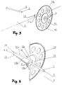
- Figures 3 and 4 show the clamp that can be fitted to the end of the roughened 1 fibre-reinforced plastic draw-stem 2 extending out from the borehole of the drilled heat insulation element 5.
- the clamp is formed by a ball-and-socket type clamping disc 12, a carrying piece 11a with a round head 11, and clamp jaws 9. Due to the use of the positioning hook 13, ball-and-socket type clamping disc 12 with a nest 12a and a passage-opening 12b, the carrying piece 11a having a positioning collar and ending in a round head 11, and the clamp jaws 9 placed in the conical hole 11b of the carrying piece 11a and secured with the positioning hook 13 all form one single unit, and so they are easy to handle and mount.
- the carrying piece 11a is pushed through the passage-opening 12b passing over the nest 12a of the ball-and-socket type clamping disc 12 in such a way that the round head 11 of the carrying piece 11a is in contact with the nest 12a of the ball-and-socket type clamping disc 12 having a spherical shell surface, while the clamp jaws 9 are fitted into the conical hole 11b of the carrying piece 11a, where they are supported by the positioning hook 13 to prevent them from sliding out of the conical hole 11b of the carrying piece 11 a.
- the positioning hook 13 catches the clamp jaws 9 at the end of the carrying piece 11a opposite the round head 11.
- Figure 4 also shows how the clamp jaws 9 caught by the positioning hook 13 fasten the rougherted 1 fibre-reinforced plastic draw-stem 2 in the conical hole 11b of the carrying piece 11 a of the round head 11 with a positioning collar 10 sitting in the ball-and-socket type clamping disc 12.
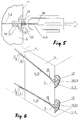
- Figure 5 shows how the clamp tightens the roughened 1 fibre-reinforced plastic draw-stem 2 with the help of a suitable flanged stem-drawing tool 15 in order to fasten the heat insulation element 5.
- the flanged stem-drawing tool 15 has a drawplate 16 and a counter-spring 14. When the drawplate 16 of the flanged stem-drawing tool 15 is drawn, the counter-spring 14 pushes the clamp jaws 9 towards the heat insulation element 5, while the drawplate 16 itself draws the draw-stem 2 towards itself during its relative displacement towards the heat insulation element 5.
- the flanged stem-drawing tool 15 bears up against the round head 11 and pushes the round head 11 up along the roughened 1 fibre-reinforced plastic draw-stem 2, and by permanently pushing forward the clamp jaws too with the help of the counter-spring 14 it also ensures a permanent clamping connection between the draw-stem 2 and the ball-and-socket type clamping disc 12.
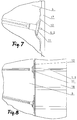
- Figure 7 shows a possible fitted position of the retaining unit, where the roughened 1 fibre-reinforced plastic draw-stem 2 is situated below the plastering 17 applied onto the heat insulation element 5.
- the draw-stem 2 must be cut off before the round head fitting into the nest 12a of the ball-and-socket type clamping disc 12.
- a decorative brick or other stone wall surfacing 18 is built in front of the heat insulation element 5, by keeping an appropriate length of the roughened 1 fibre-reinforced plastic draw-stem 2 extending over the round head 11 fitting into the nest 12a of the ball-and-socket type clamping disc 12, and by fixing it in the grouting in the decorative brick or other stone wall surfacing 18, it retains the wall surfacing 18 anchored back, free from thermal bridges, as shown in figure 8 .
- the retaining unit according to the invention can be favourably used for the simple and quick fixing of all types of heat insulation elements to a supporting structure while saving physical labour, materials and energy.
- List of references 1 roughening 2 draw-stem 3 female cone 4 supporting structure 5 heat insulation element 6 cylinder-footed tightening wedge 6a slit 7 rigid punch-tube 8 cylindrical-conical tightening wedge 8a slit 9 clamp jaw 10 positioning collar 11 round head 11a carrying piece 11b conical hole 12 ball-and-socket type clamping disc 12a nest 12b passage-opening 13 positioning hook 14 counter-spring 15 flanged stem-drawing tool 16 drawplate 17 plastering 18 wall surfacing
Landscapes
- Engineering & Computer Science (AREA)
- General Engineering & Computer Science (AREA)
- Physics & Mathematics (AREA)
- Architecture (AREA)
- Mechanical Engineering (AREA)
- Acoustics & Sound (AREA)
- Electromagnetism (AREA)
- Civil Engineering (AREA)
- Structural Engineering (AREA)
- Joining Of Building Structures In Genera (AREA)
- Finger-Pressure Massage (AREA)
- Clamps And Clips (AREA)
Claims (8)
- Die Einheit zur Befestigung von Wärmedämmung Elemente zu einer tragenden Struktur, bestehend aus einem Draw-Schaft (2), eine Verschärfung Stück geeignet für die Befestigung der Draw-Schaft (2) an der Tragkonstruktion (4) und eine Klemme zum Befestigen der Wärmedämmung Element (5) an der Zugstange (2), wo die Schelle hat einen Ball-and-socket Typ Klemmscheibe (12) mit einem Nest (12a) und eine Passage - die Öffnung (12b), und ein tragendes Stück (11a) mit einem runden Kopf (11), wo die runden Kopf (11) Der Satz (11a) angebracht ist, in das Nest (12a) der Kugel-und-Buchse Typ Klemmscheibe (12) in einer Weise Es herum zu drehen, und dem Buchwert Stück (11a) durch den Kanal-Öffnung (12b) der Kugel-und-Buchse Typ Klemmscheibe (12), dadurch gekennzeichnet, dass die äußere Oberfläche des draw-Schaft (2) ist angeraut (1) und eine Metal Female Lagerkegel (3) befestigt ist in einer festen Position an das Ende der Zugstange (2) Neben der Tragkonstruktion (4) und einem Zylinder-footed anziehen Keil (6) zog auf den Draw-Schaft (2) ist für die weiblichen Lagerkegel (3), und so die Verschärfung Stück wird gebildet durch die weibliche Kegel (3) und die Zylinder-footed anziehen Keil (6) zusammen, während in der Tragetasche Stück (11a) des runden Kopf (11) Es ist ein konischer Loch (11b), Klemmbacken (9) mit einer Positionierung des Hakens (13) montiert sind, in die konische Bohrung (11b) und die Oberfläche aufgeraut (1) der Zugstange (2) ist in Kontakt mit den Klemmbacken (9).
- Die Einheit wie in Anspruch 1, dadurch gekennzeichnet, dass der Ventilschaft (2) ist aus faserverstärktem Kunststoff.
- Die Einheit wie in Anspruch 1 oder 2, dadurch gekennzeichnet, dass der Zylinder-footed anziehen Keil (6) wird vorübergehend auf den Draw-Schaft (2), und Er ist gekoppelt mit einer starren Punch-Rohr (7), um zu verhindern, dass die Zylinder-footed anziehen Keil (6) aus dem zurückschieben.
- Die Einheit wie in einem der Ansprüche 1-3, dadurch gekennzeichnet, dass eine oder mehrere zylindrisch-konischen Keile (8) festzuziehen sind zwischen den Zylinder-footed anziehen Keil (6) und die weibliche Lagerkegel (3) des draw-Schaft (2).
- Die Einheit wie in einem der Ansprüche 1-4, dadurch gekennzeichnet, dass eine Positionierung der Muffe (10) wird auf die Durchführung Stück (11a) des runden Kopf (11), und den Teil des Kugel-und-Buchse Typ Klemmscheibe (12) liegt in der Nähe der Passage - die Öffnung (12b) ist gespannt zwischen der Positionierung Muffe (10) und den runden Kopf (11) Der Satz (11a), so dass sie nicht verschoben werden.
- Die Einheit wie in Anspruch 5, dadurch gekennzeichnet, dass der Ball-and-socket Typ Klemmscheibe (12) und der Satz (11a) mit einem runden Kopf (11) bildet die Klammer und die Klemmbacken (9) Mit der Positionierung des Hakens (13) bilden eine passende Einheit.
- Die Einheit wie in einem der Ansprüche 1-6, dadurch gekennzeichnet, dass in der Position der Einheit, auf der Seite der Kugel-und-Buchse Typ Klemmscheibe (12) Gegenüber der Wärmedämmung Element (5) Die aufgeraute (1) Draw-Schaft (2) endet in der externen Ebene des Kugel-und-Buchse Typ Klemmscheibe (12).
- Die Einheit wie in einem der Ansprüche 1-6, dadurch gekennzeichnet, dass in der Position der Einheit, auf der Seite der Kugel-und-Buchse Typ Klemmscheibe (12) Gegenüber der Wärmedämmung Element (5) Die aufgeraute (1) Draw-Schaft (2) erstreckt sich über die externe Ebene des Kugel-und-Buchse Typ Klemmscheibe (12).
Applications Claiming Priority (2)
| Application Number | Priority Date | Filing Date | Title |
|---|---|---|---|
| HU1000673A HU229785B1 (en) | 2010-12-17 | 2010-12-17 | Fastening unit with ball joint for mounting thermal insulation |
| PCT/HU2011/000125 WO2012080761A1 (en) | 2010-12-17 | 2011-12-15 | Retaining unit for fixing heat insulation elements to a supporting structure |
Publications (2)
| Publication Number | Publication Date |
|---|---|
| EP2652218A1 EP2652218A1 (de) | 2013-10-23 |
| EP2652218B1 true EP2652218B1 (de) | 2016-05-11 |
Family
ID=89990124
Family Applications (1)
| Application Number | Title | Priority Date | Filing Date |
|---|---|---|---|
| EP11805167.1A Active EP2652218B1 (de) | 2010-12-17 | 2011-12-15 | Halteeinrichtung zur befestigung von wärmedämmstoffelementen an einer trägerstruktur |
Country Status (3)
| Country | Link |
|---|---|
| EP (1) | EP2652218B1 (de) |
| HU (1) | HU229785B1 (de) |
| WO (1) | WO2012080761A1 (de) |
Families Citing this family (1)
| Publication number | Priority date | Publication date | Assignee | Title |
|---|---|---|---|---|
| HUP2200015A1 (hu) * | 2022-01-20 | 2023-07-28 | Gabor Fazakas | Csuklós szorítótárcsa érdesített pofájú szorítópatronnal sima húzószáron feszítõ kónuszon csavarvonal palástú belsõ kónuszos furatú feszítõékkel hõszigetelés szereléséhez |
Family Cites Families (7)
| Publication number | Priority date | Publication date | Assignee | Title |
|---|---|---|---|---|
| US2427392A (en) * | 1944-11-25 | 1947-09-16 | Oliver C Eckel | Clip |
| DE4323989A1 (de) | 1993-07-17 | 1995-01-19 | Fischer Artur Werke Gmbh | Dämmstoffhalter |
| EP0808397B1 (de) | 1995-02-07 | 1999-06-02 | Manfred Hoffmann | Bauwerk mit von distanzstücken gehaltenem gurtnetz und von diesem getragener hinterlüfteter fassade |
| DE10134960A1 (de) * | 2001-06-12 | 2002-12-19 | Helmut Stoffel | Befestigungselement |
| DE202005009853U1 (de) | 2005-06-21 | 2005-09-01 | Kentfa Advanced Technology Corp. | Klappbares Elektro-Fahrrad |
| US8214997B2 (en) * | 2006-04-29 | 2012-07-10 | Richie Roy A | Anchor structure with bidirectionally deflectable bore gripping fingers |
| US20090019812A1 (en) * | 2007-07-18 | 2009-01-22 | Steve Getz | Anchoring Apparatus and Method |
-
2010
- 2010-12-17 HU HU1000673A patent/HU229785B1/hu not_active IP Right Cessation
-
2011
- 2011-12-15 WO PCT/HU2011/000125 patent/WO2012080761A1/en not_active Ceased
- 2011-12-15 EP EP11805167.1A patent/EP2652218B1/de active Active
Also Published As
| Publication number | Publication date |
|---|---|
| HUP1000673A2 (en) | 2012-08-28 |
| HU1000673D0 (en) | 2011-02-28 |
| WO2012080761A1 (en) | 2012-06-21 |
| HU229785B1 (en) | 2014-07-28 |
| EP2652218A1 (de) | 2013-10-23 |
Similar Documents
| Publication | Publication Date | Title |
|---|---|---|
| US20100037552A1 (en) | Side mounted drill bolt and threaded anchor system for veneer wall tie connection | |
| US8756870B2 (en) | Roof clamp | |
| EP2762654B1 (de) | Stützstruktur für solarlichtdachplatten | |
| KR101515937B1 (ko) | 말발굽 브라켓을 이용한 건물의 판넬 시공장치 | |
| EP2250329A1 (de) | Dachschindelklammer | |
| KR20220118569A (ko) | 결합 장치, 연관된 부품들, 및 그것의 사용 방법 | |
| KR101669597B1 (ko) | 건축용 세트 앵커형 지지구 | |
| TW201221817A (en) | Furring strip fastening member and construction structure using the same | |
| KR101483632B1 (ko) | 단열재용 유니버셜 인서트 | |
| EP2652218B1 (de) | Halteeinrichtung zur befestigung von wärmedämmstoffelementen an einer trägerstruktur | |
| US9470254B2 (en) | Combination having an anchor for panel-like components, and a fixing arrangement | |
| WO2018201245A1 (en) | Shelf angle support | |
| CN205712561U (zh) | 一种预制墙板 | |
| EP2942451B1 (de) | Befestigungsorrichtung für leiste | |
| US20070269263A1 (en) | Fastener System | |
| JP2010203097A (ja) | 壁面ボルト固定部材とその取り付け工法 | |
| CN211473183U (zh) | 一种具有无应力功能的旋进式背栓 | |
| JP2011214243A (ja) | 建築物の外断熱工法及び支持金具 | |
| JP5940003B2 (ja) | 屋根上設置物の取り付け金具 | |
| KR100620253B1 (ko) | 거푸집설치용 거푸집판넬 및 그 제조방법 | |
| JP2008291549A (ja) | 荷重受支持ブラケット | |
| JP6744617B2 (ja) | 建物躯体に外装板を取り付けるためのアンカー金物 | |
| JP3082134U (ja) | 筋交い用固定金具 | |
| JP2014145154A (ja) | 後施工曲折アンカーボルトとその施工方法 | |
| EP2273212A2 (de) | Befestigungselement für Dachaufbauten, insbesondere Solaranlagen, Dachaufbau mit einem derartigen Befestigungselement und Verfahren zur Befestigung eines Teils einer Solaranlage |
Legal Events
| Date | Code | Title | Description |
|---|---|---|---|
| PUAI | Public reference made under article 153(3) epc to a published international application that has entered the european phase |
Free format text: ORIGINAL CODE: 0009012 |
|
| 17P | Request for examination filed |
Effective date: 20130617 |
|
| AK | Designated contracting states |
Kind code of ref document: A1 Designated state(s): AL AT BE BG CH CY CZ DE DK EE ES FI FR GB GR HR HU IE IS IT LI LT LU LV MC MK MT NL NO PL PT RO RS SE SI SK SM TR |
|
| AX | Request for extension of the european patent |
Extension state: BA ME |
|
| REG | Reference to a national code |
Ref country code: DE Ref legal event code: R079 Ref document number: 602011026555 Country of ref document: DE Free format text: PREVIOUS MAIN CLASS: E04B0001760000 Ipc: F16B0013120000 |
|
| GRAP | Despatch of communication of intention to grant a patent |
Free format text: ORIGINAL CODE: EPIDOSNIGR1 |
|
| RIC1 | Information provided on ipc code assigned before grant |
Ipc: E04B 1/76 20060101ALI20151214BHEP Ipc: F16B 13/06 20060101ALI20151214BHEP Ipc: F16B 13/12 20060101AFI20151214BHEP Ipc: F16B 7/02 20060101ALI20151214BHEP |
|
| INTG | Intention to grant announced |
Effective date: 20160113 |
|
| GRAS | Grant fee paid |
Free format text: ORIGINAL CODE: EPIDOSNIGR3 |
|
| GRAA | (expected) grant |
Free format text: ORIGINAL CODE: 0009210 |
|
| AK | Designated contracting states |
Kind code of ref document: B1 Designated state(s): AL AT BE BG CH CY CZ DE DK EE ES FI FR GB GR HR HU IE IS IT LI LT LU LV MC MK MT NL NO PL PT RO RS SE SI SK SM TR |
|
| AX | Request for extension of the european patent |
Extension state: BA ME |
|
| REG | Reference to a national code |
Ref country code: GB Ref legal event code: FG4D |
|
| REG | Reference to a national code |
Ref country code: CH Ref legal event code: EP |
|
| REG | Reference to a national code |
Ref country code: AT Ref legal event code: REF Ref document number: 798905 Country of ref document: AT Kind code of ref document: T Effective date: 20160515 |
|
| REG | Reference to a national code |
Ref country code: IE Ref legal event code: FG4D |
|
| REG | Reference to a national code |
Ref country code: DE Ref legal event code: R096 Ref document number: 602011026555 Country of ref document: DE |
|
| REG | Reference to a national code |
Ref country code: LT Ref legal event code: MG4D |
|
| REG | Reference to a national code |
Ref country code: NL Ref legal event code: MP Effective date: 20160511 |
|
| REG | Reference to a national code |
Ref country code: CH Ref legal event code: NV Representative=s name: KATZAROV S.A., CH |
|
| PG25 | Lapsed in a contracting state [announced via postgrant information from national office to epo] |
Ref country code: LT Free format text: LAPSE BECAUSE OF FAILURE TO SUBMIT A TRANSLATION OF THE DESCRIPTION OR TO PAY THE FEE WITHIN THE PRESCRIBED TIME-LIMIT Effective date: 20160511 Ref country code: NL Free format text: LAPSE BECAUSE OF FAILURE TO SUBMIT A TRANSLATION OF THE DESCRIPTION OR TO PAY THE FEE WITHIN THE PRESCRIBED TIME-LIMIT Effective date: 20160511 Ref country code: FI Free format text: LAPSE BECAUSE OF FAILURE TO SUBMIT A TRANSLATION OF THE DESCRIPTION OR TO PAY THE FEE WITHIN THE PRESCRIBED TIME-LIMIT Effective date: 20160511 Ref country code: NO Free format text: LAPSE BECAUSE OF FAILURE TO SUBMIT A TRANSLATION OF THE DESCRIPTION OR TO PAY THE FEE WITHIN THE PRESCRIBED TIME-LIMIT Effective date: 20160811 |
|
| REG | Reference to a national code |
Ref country code: AT Ref legal event code: MK05 Ref document number: 798905 Country of ref document: AT Kind code of ref document: T Effective date: 20160511 |
|
| PG25 | Lapsed in a contracting state [announced via postgrant information from national office to epo] |
Ref country code: PT Free format text: LAPSE BECAUSE OF FAILURE TO SUBMIT A TRANSLATION OF THE DESCRIPTION OR TO PAY THE FEE WITHIN THE PRESCRIBED TIME-LIMIT Effective date: 20160912 Ref country code: LV Free format text: LAPSE BECAUSE OF FAILURE TO SUBMIT A TRANSLATION OF THE DESCRIPTION OR TO PAY THE FEE WITHIN THE PRESCRIBED TIME-LIMIT Effective date: 20160511 Ref country code: RS Free format text: LAPSE BECAUSE OF FAILURE TO SUBMIT A TRANSLATION OF THE DESCRIPTION OR TO PAY THE FEE WITHIN THE PRESCRIBED TIME-LIMIT Effective date: 20160511 Ref country code: ES Free format text: LAPSE BECAUSE OF FAILURE TO SUBMIT A TRANSLATION OF THE DESCRIPTION OR TO PAY THE FEE WITHIN THE PRESCRIBED TIME-LIMIT Effective date: 20160511 Ref country code: SE Free format text: LAPSE BECAUSE OF FAILURE TO SUBMIT A TRANSLATION OF THE DESCRIPTION OR TO PAY THE FEE WITHIN THE PRESCRIBED TIME-LIMIT Effective date: 20160511 Ref country code: GR Free format text: LAPSE BECAUSE OF FAILURE TO SUBMIT A TRANSLATION OF THE DESCRIPTION OR TO PAY THE FEE WITHIN THE PRESCRIBED TIME-LIMIT Effective date: 20160812 Ref country code: HR Free format text: LAPSE BECAUSE OF FAILURE TO SUBMIT A TRANSLATION OF THE DESCRIPTION OR TO PAY THE FEE WITHIN THE PRESCRIBED TIME-LIMIT Effective date: 20160511 |
|
| REG | Reference to a national code |
Ref country code: FR Ref legal event code: PLFP Year of fee payment: 6 |
|
| PG25 | Lapsed in a contracting state [announced via postgrant information from national office to epo] |
Ref country code: IT Free format text: LAPSE BECAUSE OF FAILURE TO SUBMIT A TRANSLATION OF THE DESCRIPTION OR TO PAY THE FEE WITHIN THE PRESCRIBED TIME-LIMIT Effective date: 20160511 |
|
| PG25 | Lapsed in a contracting state [announced via postgrant information from national office to epo] |
Ref country code: CZ Free format text: LAPSE BECAUSE OF FAILURE TO SUBMIT A TRANSLATION OF THE DESCRIPTION OR TO PAY THE FEE WITHIN THE PRESCRIBED TIME-LIMIT Effective date: 20160511 Ref country code: RO Free format text: LAPSE BECAUSE OF FAILURE TO SUBMIT A TRANSLATION OF THE DESCRIPTION OR TO PAY THE FEE WITHIN THE PRESCRIBED TIME-LIMIT Effective date: 20160511 Ref country code: EE Free format text: LAPSE BECAUSE OF FAILURE TO SUBMIT A TRANSLATION OF THE DESCRIPTION OR TO PAY THE FEE WITHIN THE PRESCRIBED TIME-LIMIT Effective date: 20160511 Ref country code: SK Free format text: LAPSE BECAUSE OF FAILURE TO SUBMIT A TRANSLATION OF THE DESCRIPTION OR TO PAY THE FEE WITHIN THE PRESCRIBED TIME-LIMIT Effective date: 20160511 Ref country code: DK Free format text: LAPSE BECAUSE OF FAILURE TO SUBMIT A TRANSLATION OF THE DESCRIPTION OR TO PAY THE FEE WITHIN THE PRESCRIBED TIME-LIMIT Effective date: 20160511 |
|
| REG | Reference to a national code |
Ref country code: DE Ref legal event code: R097 Ref document number: 602011026555 Country of ref document: DE |
|
| PG25 | Lapsed in a contracting state [announced via postgrant information from national office to epo] |
Ref country code: BE Free format text: LAPSE BECAUSE OF FAILURE TO SUBMIT A TRANSLATION OF THE DESCRIPTION OR TO PAY THE FEE WITHIN THE PRESCRIBED TIME-LIMIT Effective date: 20160511 Ref country code: AT Free format text: LAPSE BECAUSE OF FAILURE TO SUBMIT A TRANSLATION OF THE DESCRIPTION OR TO PAY THE FEE WITHIN THE PRESCRIBED TIME-LIMIT Effective date: 20160511 Ref country code: SM Free format text: LAPSE BECAUSE OF FAILURE TO SUBMIT A TRANSLATION OF THE DESCRIPTION OR TO PAY THE FEE WITHIN THE PRESCRIBED TIME-LIMIT Effective date: 20160511 Ref country code: PL Free format text: LAPSE BECAUSE OF FAILURE TO SUBMIT A TRANSLATION OF THE DESCRIPTION OR TO PAY THE FEE WITHIN THE PRESCRIBED TIME-LIMIT Effective date: 20160511 |
|
| PLBE | No opposition filed within time limit |
Free format text: ORIGINAL CODE: 0009261 |
|
| STAA | Information on the status of an ep patent application or granted ep patent |
Free format text: STATUS: NO OPPOSITION FILED WITHIN TIME LIMIT |
|
| 26N | No opposition filed |
Effective date: 20170214 |
|
| PG25 | Lapsed in a contracting state [announced via postgrant information from national office to epo] |
Ref country code: SI Free format text: LAPSE BECAUSE OF FAILURE TO SUBMIT A TRANSLATION OF THE DESCRIPTION OR TO PAY THE FEE WITHIN THE PRESCRIBED TIME-LIMIT Effective date: 20160511 |
|
| PG25 | Lapsed in a contracting state [announced via postgrant information from national office to epo] |
Ref country code: MC Free format text: LAPSE BECAUSE OF FAILURE TO SUBMIT A TRANSLATION OF THE DESCRIPTION OR TO PAY THE FEE WITHIN THE PRESCRIBED TIME-LIMIT Effective date: 20160511 |
|
| GBPC | Gb: european patent ceased through non-payment of renewal fee |
Effective date: 20161215 |
|
| REG | Reference to a national code |
Ref country code: IE Ref legal event code: MM4A |
|
| PG25 | Lapsed in a contracting state [announced via postgrant information from national office to epo] |
Ref country code: LU Free format text: LAPSE BECAUSE OF NON-PAYMENT OF DUE FEES Effective date: 20161215 |
|
| PG25 | Lapsed in a contracting state [announced via postgrant information from national office to epo] |
Ref country code: IE Free format text: LAPSE BECAUSE OF NON-PAYMENT OF DUE FEES Effective date: 20161215 Ref country code: GB Free format text: LAPSE BECAUSE OF NON-PAYMENT OF DUE FEES Effective date: 20161215 |
|
| REG | Reference to a national code |
Ref country code: FR Ref legal event code: PLFP Year of fee payment: 7 |
|
| PGFP | Annual fee paid to national office [announced via postgrant information from national office to epo] |
Ref country code: DE Payment date: 20171215 Year of fee payment: 7 Ref country code: FR Payment date: 20171220 Year of fee payment: 7 |
|
| PGFP | Annual fee paid to national office [announced via postgrant information from national office to epo] |
Ref country code: CH Payment date: 20171215 Year of fee payment: 7 |
|
| REG | Reference to a national code |
Ref country code: CH Ref legal event code: PCAR Free format text: NEW ADDRESS: AVENUE DES MORGINES 12, 1213 PETIT-LANCY (CH) |
|
| PG25 | Lapsed in a contracting state [announced via postgrant information from national office to epo] |
Ref country code: HU Free format text: LAPSE BECAUSE OF FAILURE TO SUBMIT A TRANSLATION OF THE DESCRIPTION OR TO PAY THE FEE WITHIN THE PRESCRIBED TIME-LIMIT; INVALID AB INITIO Effective date: 20111215 Ref country code: CY Free format text: LAPSE BECAUSE OF FAILURE TO SUBMIT A TRANSLATION OF THE DESCRIPTION OR TO PAY THE FEE WITHIN THE PRESCRIBED TIME-LIMIT Effective date: 20160511 |
|
| PG25 | Lapsed in a contracting state [announced via postgrant information from national office to epo] |
Ref country code: MK Free format text: LAPSE BECAUSE OF FAILURE TO SUBMIT A TRANSLATION OF THE DESCRIPTION OR TO PAY THE FEE WITHIN THE PRESCRIBED TIME-LIMIT Effective date: 20160511 Ref country code: IS Free format text: LAPSE BECAUSE OF FAILURE TO SUBMIT A TRANSLATION OF THE DESCRIPTION OR TO PAY THE FEE WITHIN THE PRESCRIBED TIME-LIMIT Effective date: 20160511 |
|
| PG25 | Lapsed in a contracting state [announced via postgrant information from national office to epo] |
Ref country code: BG Free format text: LAPSE BECAUSE OF FAILURE TO SUBMIT A TRANSLATION OF THE DESCRIPTION OR TO PAY THE FEE WITHIN THE PRESCRIBED TIME-LIMIT Effective date: 20160511 |
|
| PG25 | Lapsed in a contracting state [announced via postgrant information from national office to epo] |
Ref country code: MT Free format text: LAPSE BECAUSE OF NON-PAYMENT OF DUE FEES Effective date: 20161215 |
|
| PG25 | Lapsed in a contracting state [announced via postgrant information from national office to epo] |
Ref country code: TR Free format text: LAPSE BECAUSE OF FAILURE TO SUBMIT A TRANSLATION OF THE DESCRIPTION OR TO PAY THE FEE WITHIN THE PRESCRIBED TIME-LIMIT Effective date: 20160511 Ref country code: AL Free format text: LAPSE BECAUSE OF FAILURE TO SUBMIT A TRANSLATION OF THE DESCRIPTION OR TO PAY THE FEE WITHIN THE PRESCRIBED TIME-LIMIT Effective date: 20160511 |
|
| REG | Reference to a national code |
Ref country code: DE Ref legal event code: R119 Ref document number: 602011026555 Country of ref document: DE |
|
| REG | Reference to a national code |
Ref country code: CH Ref legal event code: PL |
|
| PG25 | Lapsed in a contracting state [announced via postgrant information from national office to epo] |
Ref country code: DE Free format text: LAPSE BECAUSE OF NON-PAYMENT OF DUE FEES Effective date: 20190702 Ref country code: FR Free format text: LAPSE BECAUSE OF NON-PAYMENT OF DUE FEES Effective date: 20181231 |
|
| PG25 | Lapsed in a contracting state [announced via postgrant information from national office to epo] |
Ref country code: CH Free format text: LAPSE BECAUSE OF NON-PAYMENT OF DUE FEES Effective date: 20181231 Ref country code: LI Free format text: LAPSE BECAUSE OF NON-PAYMENT OF DUE FEES Effective date: 20181231 |