US9522575B2 - Agricultural bar nose to prevent stubble damage - Google Patents
Agricultural bar nose to prevent stubble damage Download PDFInfo
- Publication number
- US9522575B2 US9522575B2 US13/400,881 US201213400881A US9522575B2 US 9522575 B2 US9522575 B2 US 9522575B2 US 201213400881 A US201213400881 A US 201213400881A US 9522575 B2 US9522575 B2 US 9522575B2
- Authority
- US
- United States
- Prior art keywords
- nose
- tire
- lug
- edge
- tread
- Prior art date
- Legal status (The legal status is an assumption and is not a legal conclusion. Google has not performed a legal analysis and makes no representation as to the accuracy of the status listed.)
- Active, expires
Links
Images


Classifications
-
- B—PERFORMING OPERATIONS; TRANSPORTING
- B60—VEHICLES IN GENERAL
- B60C—VEHICLE TYRES; TYRE INFLATION; TYRE CHANGING; CONNECTING VALVES TO INFLATABLE ELASTIC BODIES IN GENERAL; DEVICES OR ARRANGEMENTS RELATED TO TYRES
- B60C11/00—Tyre tread bands; Tread patterns; Anti-skid inserts
- B60C11/03—Tread patterns
- B60C11/0311—Patterns comprising tread lugs arranged parallel or oblique to the axis of rotation
- B60C11/0316—Patterns comprising tread lugs arranged parallel or oblique to the axis of rotation further characterised by the groove cross-section
-
- B—PERFORMING OPERATIONS; TRANSPORTING
- B60—VEHICLES IN GENERAL
- B60C—VEHICLE TYRES; TYRE INFLATION; TYRE CHANGING; CONNECTING VALVES TO INFLATABLE ELASTIC BODIES IN GENERAL; DEVICES OR ARRANGEMENTS RELATED TO TYRES
- B60C11/00—Tyre tread bands; Tread patterns; Anti-skid inserts
- B60C11/03—Tread patterns
- B60C11/0311—Patterns comprising tread lugs arranged parallel or oblique to the axis of rotation
- B60C2011/0313—Patterns comprising tread lugs arranged parallel or oblique to the axis of rotation directional type
-
- B—PERFORMING OPERATIONS; TRANSPORTING
- B60—VEHICLES IN GENERAL
- B60C—VEHICLE TYRES; TYRE INFLATION; TYRE CHANGING; CONNECTING VALVES TO INFLATABLE ELASTIC BODIES IN GENERAL; DEVICES OR ARRANGEMENTS RELATED TO TYRES
- B60C2200/00—Tyres specially adapted for particular applications
- B60C2200/08—Tyres specially adapted for particular applications for agricultural vehicles
Definitions
- the present invention relates generally to agricultural tires, and more particularly, but not by way of limitation, to tires for use in grain fields or the like where the tires are sometimes damaged by engagement with sharp stubbles of grain which has been cut.
- FIG. 1 shows a typical prior art agricultural tire 10 having first and second rows of tread lugs such as 12 and 14 .
- Each of the tread lugs has a leading edge with a straight nose edge portion such as 16 .
- FIG. 2 is an enlarged view of the lug 12 of FIG. 1 and further identifies the straight nose edge 16 .
- a nose wall 18 extends downward from the nose edge 16 to a tread floor 20 .
- the nose wall 18 is typically at a very shallow angle 22 in the range of from 0° to 18° to a radial line 24 extending from the rotational axis of the tire 10 .
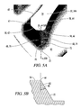
- FIG. 3 is a photograph of a prior art tire like the tire 10 illustrating such damage at the base of the nose wall of two lugs.
- FIG. 4 is an enlarged view of the uppermost portion of FIG. 3 further illustrating the damage to the lower portion of the nose wall of the lug.
- a pneumatic agricultural tire in a first embodiment includes a circumferential tread portion including first and second rows of tread lugs extending from first and second shoulders of the tread portion toward an equatorial plane of the tire.
- the tread lugs extend upward from a tread floor by a lug height.
- the lugs extend at an angle to a rotational axis of the tire to define a rotational direction of the tire such that when the tire is rolling in a forward direction an axially inner end of each lug engages the ground before an axially outer end of the lug engages the ground.
- Each lug has a radially outer ground engaging surface defined between a leading edge of the lug and a trailing edge of the lug.
- each lug includes an inside leading edge facing partially toward the equatorial plane, an outside leading edge facing partially toward the respective shoulder from which the lug extends, and a nose edge joining the inside leading edge and the outside leading edge.
- a nose wall extends upward from the tread floor to the nose edge.
- the nose wall has a leading root portion having a nose ridge extending upward from the tread floor to at least one-half the tread height.
- the nose ridge has a radius of curvature of no greater than 1 ⁇ 2 inch.
- the nose ridge extends at a nose angle of from about 20° to about 60° to a radial plane.
- each lug of a pneumatic agricultural tire has a radially outer ground engaging surface defined between a leading edge of the lug and a trailing edge of the lug.
- the leading edge of each lug includes an inside leading edge facing partially toward the equatorial plane and an outside leading edge facing partially toward the respective shoulder from which the lug extends.
- Each lug has a leading wall rising up from the tread floor to the leading edge.
- the leading wall includes a wedge shaped leading nose rising up from the tread floor and sloped in the trailing direction, so that ground stubble is engaged by and pushed aside by the wedge shaped leading nose thereby reducing stubble damage at a root of the leading wall.
- FIG. 1 is a perspective view of a prior art agricultural tire.
- FIG. 2 is an enlarged view of the tire of FIG. 1 .
- FIG. 2A is a cross-section along line 2 A- 2 A of FIG. 2 .
- FIG. 3 is a photograph of a tire like that of FIG. 1 showing stubble damage.
- FIG. 4 is an enlarged photograph of the stubble damage of FIG. 3 .
- FIG. 5 is a perspective view of the tread portion of a tire incorporating a first embodiment of the lug design of the present invention.
- FIG. 5A is an enlarged schematic view of one of the axially inner lug ends of the tire of FIG. 5 indicating the major break lines and the outer surface of the lug wall.
- FIG. 5B is a sectioned view taken along line 5 B- 5 B of FIG. 5A showing the nose ridge angle.
- FIG. 6A is an enlarged schematic view of one of the axially inner lug ends of the tire of FIG. 6 indicating the major break lines and the outer surface of the lug wall.
- FIG. 6B is a sectioned view taken along line 6 B- 6 B of FIG. 6A showing the nose ridge angle.
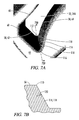
- FIG. 7 is a view similar to FIG. 5 showing a third embodiment of the lug design of the present invention.
- FIG. 7A is an enlarged schematic view of one of the axially inner lug ends of the tire of FIG. 7 indicating the major break lines and the outer surface of the lug wall.
- FIG. 7B is a sectioned view taken along line 7 B- 7 B of FIG. 7A showing the nose ridge angle.
- FIG. 8 is a schematic radially sectioned view of a tire like that of FIG. 5 .
- FIG. 9 is a schematic laid out view of the ground engaging surfaces of the lugs of the tread portion of the tire of FIG. 5 .
- “Circumferential” refers to lines or directions extending along the perimeter of the surface of the annular tread perpendicular to the axial direction.
- Equatorial plane refers to a plane that is perpendicular to the axis of rotation of a tire and passes through the center of the tire's tread.
- axially inward and axially inwardly refer to a general direction towards the equatorial plane of the tire, whereas “axially outward” and “axially outwardly” refer to a general direction away from the equatorial plane of the tire and towards the sidewall of the tire.
- FIG. 5 a first embodiment of a pneumatic agricultural tire is shown and generally designated by the numeral 30 .
- a radial cross-section of the tire 30 is schematically shown in FIG. 8 .
- a laid out view of the ground engaging surface of the tire of FIG. 5 is shown in FIG. 9 .
- Some non-limiting examples of agricultural implements which may utilize the tire design disclosed herein include tractors (both front and rear tires), self-propelled sprayers, combines, powered implements and the like.
- the tire 30 includes a circumferential tread portion 32 including first and second rows of tread lugs 34 and 36 extending from first and second shoulders 38 and 40 of the tread portion toward an equatorial plane 42 of the tire.
- the individual lugs of the first row 34 may be identified as 34 A, 34 B, etc. as indicated in FIG. 5 .
- the tread lugs 34 and 36 extend upward from a tread floor 44 by a lug height 46 .
- Each lug 34 and 36 preferably extends substantially to but does not cross the equatorial plane 42 .
- the lugs extend at a lug angle 48 to a rotational axis 50 of the tire to define a rotational direction of the tire such that when the tire is rolling in a forward direction an axially inner end 52 of each lug engages the ground before an axially outer end 54 of the lug engages the ground.
- Each lug has a radially outer ground engaging surface such as the surface 56 of lug 34 A identified in FIG. 5 , and in the enlarged view of FIG. 5A .
- the radially outer ground engaging surface 56 is defined between a leading edge 58 of the lug and a trailing edge 60 of the lug.
- the leading edge 58 includes an inside leading edge 62 facing partially toward the equatorial plane 42 , and an outside leading edge 64 facing partially toward the respective shoulder 38 from which the lug 34 A extends.
- the leading edge 58 further includes a nose edge 66 joining the inside leading edge 62 and the outside leading edge 64 .
- the nose edge 66 is a straight nose edge.
- the nose edge is also a straight nose edge
- the nose edge is a curved nose edge.
- the axially inner end of the radially outer surface 56 of the lug is defined by an inside lateral edge 61 extending in a substantially circumferential direction.
- a nose wall 68 extends upward from the tread floor 44 to the nose edge 66 .
- the nose wall 68 has a leading root portion 70 having a nose ridge 72 extending upward from the tread floor 44 to at least one half the tread height 46 .
- the nose ridge 72 extends substantially perpendicular to but not radially from the rotational axis 50 of the tire.
- the nose wall 68 includes first and second nose wall sides 74 and 76 extending upward from the tread floor 44 and joined at the nose ridge 72 .
- the first and second nose wall sides 74 and 76 extend all the way up to the straight nose edge 66 and thus the nose ridge 72 also extends all the way up to the straight nose edge 66 where the nose ridge 72 joins the nose edge 66 at an intermediate point 78 which preferably is approximately a mid-point of the straight nose edge 66 .
- each of the nose wall sides 76 and 78 has four edges, they are not truly planar members. They are each somewhat in the shape of a twisted four sided plane.
- the nose wall sides 74 and 76 join together to form the nose ridge 72 , the centermost line of which is designated schematically in FIG. 5A by a line, but it will be appreciated that the nose ridge 72 will always have some degree of curvature or radius.
- the nose ridge may in fact have a significant radius of curvature particularly if a curved nose edge 66 is utilized as shown in FIG. 7 .
- the nose ridge has a radius of curvature no greater than one-half inch.
- the nose ridge has a radius of curvature no greater than 0.3 inch.
- the nose ridge 72 extends at a nose angle 80 which preferably is in a range of from about 20° to about 60° to a radial plane such as 82 .
- the nose angle 82 may be in a range of from about 30° to about 50°, and in still another embodiment the nose angle may be in a range of from about 35° to about 45°.
- the straight nose edge 66 extends substantially parallel to the rotational axis 50 of the tire 30 .
- the nose wall 68 as shown in enlarged view in FIG. 5A can also be described as a leading wall 68 rising up from the tread floor 44 to the leading edge 66 .
- the leading wall 68 includes a wedge shaped leading nose formed by the nose side walls 74 and 76 and the wedge shaped leading nose rises up from the tread floor 44 and is sloped as is seen in FIG. 5B in the trailing direction by angle 80 .
- the wedge shaped leading nose formed by nose side walls 74 and 76 acts in a manner of a cow catcher or leading scoop so that ground stubble from previously cut crops which is being rolled over by the tire 30 is engaged by and pushed aside by the wedge shaped leading nose thereby reducing stubble damage at the root 70 of the leading wall 68 .
- the nose ridge 72 can be further described as a discernible nose ridge which extends from the tread floor 44 to at least one half the lug height 46 , and in the embodiment of FIG. 5A extends all the way to the nose edge 66 , thus extending the entire lug height 46 .
- FIGS. 6, 6A and 6B a second embodiment is described, which is similar to the embodiment of FIGS. 5, 5A and 5B , except for the shape of the nose wall.
- those features which are substantially identical to the features of the embodiment of FIG. 5 are identified with the same numerals used above with regard to FIG. 5 .
- FIGS. 5 and 6 are best understood with reference to the enlarged view of FIG. 6A .
- the differences lie in the shape of the nose wall and the nose wall sides.
- the nose edge 66 is still a straight nose edge such as was described above with regard to FIG. 5 .
- a modified nose wall 90 includes first and second nose wall sides 92 and 94 which extend upward from the tread floor 44 and are joined at a nose ridge 96 .
- the nose wall sides 92 and 94 , and the nose ridge 96 defined between them terminate at a height 98 which is in a range of from 25% to 100% of, and more preferably from one-half to three quarters of, the lug height 46 above the tread floor 44 . Then the nose wall sides 92 and 94 blend together into an upper nose surface 100 with no discernible nose ridge. The upper nose surface 100 extends to the straight nose edge 66 .
- FIG. 6A is schematic, and although it indicates the location of nose ridge 96 with a line, it will be understood that the nose ridge 96 and all other break lines shown schematically in FIG. 6A all have some degree of curvature. Furthermore, the lines 102 and 104 schematically indicating the locations where the nose wall sides 92 and 94 blend into the upper nose surface 100 will also have a concave curvature.
- FIG. 6B is a sectioned view along line 6 B- 6 B of FIG. 6A and generally indicates the upper nose angle 104 for the upper nose surface 100 , and the lower nose angle 106 for the nose ridge 96 .
- the upper nose angle 104 may be in a range of from about 0° to about 20°.
- the lower nose angle 106 may be in a range of from about 20° to about 60°, and more preferably in a range of from about 30° to about 50°, and most preferably in a range of from about 35° to about 45°.
- FIGS. 7, 7A and 7B differs from the embodiment of FIG. 5 in the shape of the nose edge and the nose wall. Those features which are similar to the embodiment of FIG. 5 are indicated with the same identifying numerals used with regard to FIG. 5 .
- the inside leading edge 62 and outside leading edge 64 are joined by a curved nose edge 110 having a radius of curvature 112 of no greater than one-half inch.
- the radius of curvature 112 is no greater than 0.3 inch.
- the radius of curvature 112 is approximately 0.24 inch.
- the lug of FIG. 7A has a curved slope nose wall 114 which extends all the way downward to a curved root or base 116 generally adjacent the tread floor 44 .
- a dashed line in FIG. 7A generally indicates the center line of a nose ridge 118 having a curvature similar to that of the curved nose edge 110 and extending from the tread floor 44 up to the curved nose edge 110 .
- the nose angle 120 as shown in one embodiment is in the range of from about 20° to about 60°. In another embodiment the angle 120 is in the range of from about 30° to about 50°. In still another embodiment the angle 120 is in the range of from about 35° to about 45°.
- a pneumatic agricultural tire comprising:
- a circumferential tread portion including first and second rows of tread lugs extending from first and second shoulders of the tread portion toward an equatorial plane of the tire, the tread lugs extending upward from a tread floor by a lug height;
- the lugs extending at an angle to a rotational axis of the tire to define a rotational direction of the tire such that when the tire is rolling in a forward direction an axially inner end of each lug engages the ground before an axially outer end of the lug engages the ground;
- each lug having a radially outer ground engaging surface defined between a leading edge of the lug and a trailing edge of the lug;
- each lug including an inside leading edge facing partially toward the equatorial plane, an outside leading edge facing partially toward the respective shoulder from which the lug extends, and a nose edge joining the inside leading edge and the outside leading edge;
- a nose wall extending upward from the tread floor to the nose edge, the nose wall having a leading root portion having a nose ridge extending upward from the tread floor to at least one-half the tread height, the nose ridge having a radius of curvature of no greater than 1 ⁇ 2 inch, the nose ridge extending at a nose angle of from about 20° to about 60° to a radial plane.
- the nose edge is a straight nose edge
- the nose wall includes first and second nose wall sides extending upward from the tread floor and joined at the nose ridge.
- the nose ridge extends all the way to an intermediate point of the straight nose edge.
- the intermediate point of the straight nose edge is a mid-point of the straight nose edge.
- the nose ridge terminates between one-half and three-quarters of the lug height and then the nose wall sides blend together into an upper nose surface with no discernible nose ridge, the upper nose surface extending to the straight nose edge.
- the straight nose edge extends substantially parallel to a rotational axis of the tire.
- the nose edge is a curved nose edge, having a radius of curvature of no greater than one-half inch.
- the radius of curvature of the curved nose edge is no greater than 0.3 inch.
- the nose ridge extends all the way to the curved nose edge.
- the nose angle is in a range of from about 30° to about 50°.
- the nose angle is in a range of from about 35° to about 45°.
- the nose ridge extends substantially perpendicular to, but not radially from, the rotational axis of the tire.
- each lug extends substantially to but does not cross the equatorial plane of the tire.
- an axially inner end of the radially outer surface of each lug is defined by an inside lateral edge extending in a substantially circumferential direction.
- a pneumatic agricultural tire comprising:
- a circumferential tread portion including first and second rows of tread lugs extending from first and second shoulders of the tread portion toward an equatorial plane of the tire, the tread lugs extending upward from a tread floor by a lug height;
- the lugs extending at an angle to a rotational axis of the tire to define a rotational direction of the tire such that when the tire is rolling in a forward direction an axially inner end of each lug engages the ground before an axially outer end of the lug engages the ground;
- each lug having a radially outer ground engaging surface defined between a leading edge of the lug and a trailing edge of the lug;
- each lug including an inside leading edge facing partially toward the equatorial plane, and an outside leading edge facing partially toward the respective shoulder from which the lug extends;
- each lug having a leading wall rising up from the tread floor to the leading edge, the leading wall including a wedge shaped leading nose rising up from the tread floor and sloped in the trailing direction, so that ground stubble is engaged by and pushed aside by the wedge shaped leading nose thereby reducing stubble damage at a root of the leading wall.
- the wedge shaped leading nose has a discernible nose ridge from adjacent the tread floor to at least one-half of the lug height.
- the discernible nose ridge extends all the way to the leading edge of the lug.
- the leading edge includes a curved nose edge joining the inside leading edge and the outside leading edge.
- the leading edge includes a straight nose edge joining the inside leading edge and the outside leading edge.
- the discernible nose ridge has a radius of curvature of no greater than 1 ⁇ 2 inch.
- the discernible nose ridge has a radius of curvature of no greater than 0.3 inch.
- the wedge shaped leading nose is formed by two nose wall sides rising up from the tread floor and joining at the nose ridge.
- the leading edge includes a straight nose edge joining the inside leading edge and the outside leading edge;
- the two nose wall sides extend to at least one-half of the lug height.
- the nose ridge terminates between one-half and three-quarters of the lug height and then the nose wall sides blend together into an upper nose surface with no discernible nose ridge, the upper nose surface extending to the straight nose edge.
- the two nose wall sides and the discernible nose ridge extend all the way to the straight nose edge.
Landscapes
- Engineering & Computer Science (AREA)
- Mechanical Engineering (AREA)
- Tires In General (AREA)
- Supports For Plants (AREA)
Priority Applications (9)
| Application Number | Priority Date | Filing Date | Title |
|---|---|---|---|
| US13/400,881 US9522575B2 (en) | 2012-02-21 | 2012-02-21 | Agricultural bar nose to prevent stubble damage |
| PCT/US2013/025495 WO2013126225A1 (fr) | 2012-02-21 | 2013-02-11 | Nez de guidage agricole permettant d'empêcher la détérioration de chaume |
| BR112014019629A BR112014019629A8 (pt) | 2012-02-21 | 2013-02-11 | Extremidade de barra agrícola para evitar danos de restolho |
| CN201380010092.5A CN104136240B (zh) | 2012-02-21 | 2013-02-11 | 用于防止残茬损伤的农业条鼻 |
| IN5902DEN2014 IN2014DN05902A (fr) | 2012-02-21 | 2013-02-11 | |
| JP2014556765A JP5876595B2 (ja) | 2012-02-21 | 2013-02-11 | 刈株損傷を回避するための農業用棒状ノーズ |
| EP13752505.1A EP2822783A4 (fr) | 2012-02-21 | 2013-02-11 | Nez de guidage agricole permettant d'empêcher la détérioration de chaume |
| ARP130100506A AR090090A1 (es) | 2012-02-21 | 2013-02-19 | Barras con saliente frontal en neumatico agricola para evitar el daño debido a los rastrojos |
| US15/339,975 US20170144489A1 (en) | 2012-02-21 | 2016-11-01 | Agricultural Bar Nose To Prevent Stubble Damage |
Applications Claiming Priority (1)
| Application Number | Priority Date | Filing Date | Title |
|---|---|---|---|
| US13/400,881 US9522575B2 (en) | 2012-02-21 | 2012-02-21 | Agricultural bar nose to prevent stubble damage |
Related Child Applications (1)
| Application Number | Title | Priority Date | Filing Date |
|---|---|---|---|
| US15/339,975 Continuation US20170144489A1 (en) | 2012-02-21 | 2016-11-01 | Agricultural Bar Nose To Prevent Stubble Damage |
Publications (2)
| Publication Number | Publication Date |
|---|---|
| US20130213541A1 US20130213541A1 (en) | 2013-08-22 |
| US9522575B2 true US9522575B2 (en) | 2016-12-20 |
Family
ID=48981363
Family Applications (2)
| Application Number | Title | Priority Date | Filing Date |
|---|---|---|---|
| US13/400,881 Active 2035-09-05 US9522575B2 (en) | 2012-02-21 | 2012-02-21 | Agricultural bar nose to prevent stubble damage |
| US15/339,975 Abandoned US20170144489A1 (en) | 2012-02-21 | 2016-11-01 | Agricultural Bar Nose To Prevent Stubble Damage |
Family Applications After (1)
| Application Number | Title | Priority Date | Filing Date |
|---|---|---|---|
| US15/339,975 Abandoned US20170144489A1 (en) | 2012-02-21 | 2016-11-01 | Agricultural Bar Nose To Prevent Stubble Damage |
Country Status (8)
| Country | Link |
|---|---|
| US (2) | US9522575B2 (fr) |
| EP (1) | EP2822783A4 (fr) |
| JP (1) | JP5876595B2 (fr) |
| CN (1) | CN104136240B (fr) |
| AR (1) | AR090090A1 (fr) |
| BR (1) | BR112014019629A8 (fr) |
| IN (1) | IN2014DN05902A (fr) |
| WO (1) | WO2013126225A1 (fr) |
Cited By (1)
| Publication number | Priority date | Publication date | Assignee | Title |
|---|---|---|---|---|
| US20170144489A1 (en) * | 2012-02-21 | 2017-05-25 | Bridgestone Americas Tire Operations, Llc | Agricultural Bar Nose To Prevent Stubble Damage |
Families Citing this family (3)
| Publication number | Priority date | Publication date | Assignee | Title |
|---|---|---|---|---|
| WO2015160445A1 (fr) * | 2014-04-13 | 2015-10-22 | Bridgestone Americas Tire Operations, Llc | Pneu présentant des barres incurvées |
| USD746220S1 (en) | 2014-04-13 | 2015-12-29 | Bridgestone Americas Tire Operations, Llc | Tire tread |
| FR3042199B1 (fr) * | 2015-10-08 | 2017-11-03 | Michelin & Cie | Pneumatique pour vehicule a usage agricole |
Citations (26)
| Publication number | Priority date | Publication date | Assignee | Title |
|---|---|---|---|---|
| US4186788A (en) | 1977-03-03 | 1980-02-05 | Compagnie Generale Des Etablissements Michelin | Pneumatic tire |
| JPS5847607A (ja) | 1981-09-17 | 1983-03-19 | Yokohama Rubber Co Ltd:The | ラグタイヤ |
| US4446902A (en) | 1981-08-31 | 1984-05-08 | Compagnie Generale Des Etablissements Michelin | Tires for drive wheels of agricultural tractors or similar vehicles |
| US4480672A (en) | 1983-07-11 | 1984-11-06 | The B. F. Goodrich Company | Antivibration tractor tire |
| US5010935A (en) | 1989-10-11 | 1991-04-30 | The Goodyear Tire & Rubber Company | Agricultural tire and tread lug therefor |
| US5337814A (en) | 1992-01-21 | 1994-08-16 | The Goodyear Tire & Rubber Company | Agricultural tire comprising lugs of defined height and inclination |
| US5337816A (en) | 1992-11-20 | 1994-08-16 | The Goodyear Tire & Rubber Company | Pneumatic agricultural tire |
| JPH0834210A (ja) | 1994-07-21 | 1996-02-06 | Bridgestone Corp | ラグ付空気入りタイヤ |
| JPH0885309A (ja) | 1994-09-20 | 1996-04-02 | Bridgestone Corp | 空気入りラジアルタイヤ |
| EP0795427A1 (fr) * | 1996-03-11 | 1997-09-17 | The Goodyear Tire & Rubber Company | Bandage pneumatique agricole |
| US5733394A (en) | 1995-05-19 | 1998-03-31 | The Goodyear Tire & Rubber Company | Radial agricultural tire with a pitched tread |
| JPH10338007A (ja) * | 1997-06-09 | 1998-12-22 | Ohtsu Tire & Rubber Co Ltd :The | ラグ付きタイヤ |
| US6062282A (en) | 1997-04-25 | 2000-05-16 | The Goodyear Tire & Rubber Company | Asymmetric directional pneumatic agricultural tire |
| US6179027B1 (en) | 1997-09-17 | 2001-01-30 | Bridgestone Corporation | Agricultural pneumatic tires having directional lugs |
| US6209602B1 (en) | 1999-02-03 | 2001-04-03 | The Goodyear Tire & Rubber Company | Industrial service agricultural tire |
| US6260594B1 (en) | 1997-09-22 | 2001-07-17 | The Goodyear Tire & Rubber Company | Industrial service pneumatic tire |
| US6263933B1 (en) | 1997-02-04 | 2001-07-24 | The Goodyear Tire & Rubber Company | Industrial service agricultural tire |
| JP2002347412A (ja) | 2001-05-29 | 2002-12-04 | Ohtsu Tire & Rubber Co Ltd :The | 空気入りタイヤ |
| JP2003205709A (ja) | 2001-11-12 | 2003-07-22 | Bridgestone Corp | 農業機械用タイヤ |
| KR20040027038A (ko) | 2002-09-27 | 2004-04-01 | 한국타이어 주식회사 | 배토성 및 배수성을 향상시킨 공기입 타이어 |
| US20040099359A1 (en) | 2002-11-26 | 2004-05-27 | Bonko Mark Leonard | Agricultural combine tire |
| US20040118497A1 (en) * | 2002-12-20 | 2004-06-24 | The Goodyear Tire & Rubber Company | Pneumatic tire for use on row-crop field sprayers and other like farm machinery |
| US20080142134A1 (en) | 2004-12-28 | 2008-06-19 | Bridgestone Corporation | Farm Vehicle Tyre |
| US20090084478A1 (en) * | 2007-10-01 | 2009-04-02 | Wallet Bill J | Irrigation tire |
| US7762296B2 (en) | 2006-11-24 | 2010-07-27 | Alliance Tire Americas, Inc. | Agricultural vehicle tire |
| US20130213541A1 (en) | 2012-02-21 | 2013-08-22 | Wayne Birkenholz | Agricultural Bar Nose to Prevent Stubble Damage |
Family Cites Families (2)
| Publication number | Priority date | Publication date | Assignee | Title |
|---|---|---|---|---|
| TW585009B (en) * | 2002-05-03 | 2004-04-21 | Ritdisplay Corp | Active-driving type organic electroluminescent device |
| CN201261361Y (zh) * | 2008-09-01 | 2009-06-24 | 天津国际联合轮胎橡胶有限公司 | 65系列农业子午线轮胎花纹 |
-
2012
- 2012-02-21 US US13/400,881 patent/US9522575B2/en active Active
-
2013
- 2013-02-11 CN CN201380010092.5A patent/CN104136240B/zh not_active Expired - Fee Related
- 2013-02-11 IN IN5902DEN2014 patent/IN2014DN05902A/en unknown
- 2013-02-11 BR BR112014019629A patent/BR112014019629A8/pt not_active IP Right Cessation
- 2013-02-11 WO PCT/US2013/025495 patent/WO2013126225A1/fr active Application Filing
- 2013-02-11 EP EP13752505.1A patent/EP2822783A4/fr not_active Withdrawn
- 2013-02-11 JP JP2014556765A patent/JP5876595B2/ja not_active Expired - Fee Related
- 2013-02-19 AR ARP130100506A patent/AR090090A1/es unknown
-
2016
- 2016-11-01 US US15/339,975 patent/US20170144489A1/en not_active Abandoned
Patent Citations (31)
| Publication number | Priority date | Publication date | Assignee | Title |
|---|---|---|---|---|
| US4186788A (en) | 1977-03-03 | 1980-02-05 | Compagnie Generale Des Etablissements Michelin | Pneumatic tire |
| US4446902A (en) | 1981-08-31 | 1984-05-08 | Compagnie Generale Des Etablissements Michelin | Tires for drive wheels of agricultural tractors or similar vehicles |
| JPS5847607A (ja) | 1981-09-17 | 1983-03-19 | Yokohama Rubber Co Ltd:The | ラグタイヤ |
| US4480672A (en) | 1983-07-11 | 1984-11-06 | The B. F. Goodrich Company | Antivibration tractor tire |
| US5010935A (en) | 1989-10-11 | 1991-04-30 | The Goodyear Tire & Rubber Company | Agricultural tire and tread lug therefor |
| US5337814A (en) | 1992-01-21 | 1994-08-16 | The Goodyear Tire & Rubber Company | Agricultural tire comprising lugs of defined height and inclination |
| US5337816A (en) | 1992-11-20 | 1994-08-16 | The Goodyear Tire & Rubber Company | Pneumatic agricultural tire |
| JPH0834210A (ja) | 1994-07-21 | 1996-02-06 | Bridgestone Corp | ラグ付空気入りタイヤ |
| JPH0885309A (ja) | 1994-09-20 | 1996-04-02 | Bridgestone Corp | 空気入りラジアルタイヤ |
| US5609699A (en) | 1994-09-20 | 1997-03-11 | Bridgestone Corporation | Pneumatic radial tires including a fork-shaped groove |
| US5733394A (en) | 1995-05-19 | 1998-03-31 | The Goodyear Tire & Rubber Company | Radial agricultural tire with a pitched tread |
| EP0795427A1 (fr) * | 1996-03-11 | 1997-09-17 | The Goodyear Tire & Rubber Company | Bandage pneumatique agricole |
| JPH09323508A (ja) | 1996-03-11 | 1997-12-16 | Goodyear Tire & Rubber Co:The | 農業用空気タイヤ |
| US6263933B1 (en) | 1997-02-04 | 2001-07-24 | The Goodyear Tire & Rubber Company | Industrial service agricultural tire |
| US6062282A (en) | 1997-04-25 | 2000-05-16 | The Goodyear Tire & Rubber Company | Asymmetric directional pneumatic agricultural tire |
| JPH10338007A (ja) * | 1997-06-09 | 1998-12-22 | Ohtsu Tire & Rubber Co Ltd :The | ラグ付きタイヤ |
| JP3319977B2 (ja) | 1997-06-09 | 2002-09-03 | オーツタイヤ株式会社 | ラグ付きタイヤ |
| US6179027B1 (en) | 1997-09-17 | 2001-01-30 | Bridgestone Corporation | Agricultural pneumatic tires having directional lugs |
| US6260594B1 (en) | 1997-09-22 | 2001-07-17 | The Goodyear Tire & Rubber Company | Industrial service pneumatic tire |
| US6209602B1 (en) | 1999-02-03 | 2001-04-03 | The Goodyear Tire & Rubber Company | Industrial service agricultural tire |
| JP2002347412A (ja) | 2001-05-29 | 2002-12-04 | Ohtsu Tire & Rubber Co Ltd :The | 空気入りタイヤ |
| JP2003205709A (ja) | 2001-11-12 | 2003-07-22 | Bridgestone Corp | 農業機械用タイヤ |
| KR20040027038A (ko) | 2002-09-27 | 2004-04-01 | 한국타이어 주식회사 | 배토성 및 배수성을 향상시킨 공기입 타이어 |
| US20040099359A1 (en) | 2002-11-26 | 2004-05-27 | Bonko Mark Leonard | Agricultural combine tire |
| US20040118497A1 (en) * | 2002-12-20 | 2004-06-24 | The Goodyear Tire & Rubber Company | Pneumatic tire for use on row-crop field sprayers and other like farm machinery |
| US20100243118A1 (en) | 2002-12-20 | 2010-09-30 | The Goodyear Tire & Rubber Company | Pneumatic tire for use on row-crop field sprayers and other like farm machinery |
| US20080142134A1 (en) | 2004-12-28 | 2008-06-19 | Bridgestone Corporation | Farm Vehicle Tyre |
| US7762296B2 (en) | 2006-11-24 | 2010-07-27 | Alliance Tire Americas, Inc. | Agricultural vehicle tire |
| US20090084478A1 (en) * | 2007-10-01 | 2009-04-02 | Wallet Bill J | Irrigation tire |
| US20130213541A1 (en) | 2012-02-21 | 2013-08-22 | Wayne Birkenholz | Agricultural Bar Nose to Prevent Stubble Damage |
| JP2015509881A (ja) | 2012-02-21 | 2015-04-02 | ブリヂストン アメリカズ タイヤ オペレイションズ エルエルシー | 刈株損傷を回避するための農業用棒状ノーズ |
Non-Patent Citations (5)
| Title |
|---|
| China Notification of the First Office Action (PCT Application in the National Phase) in Chinese Application for Invention No. 201380010092.5, dated Jan. 26, 2016, 2 pp. (not prior art). |
| English translation of Aug. 25, 2015 office action in corresponding Japan App. 2014-556765, 4 pp. (not prior art). |
| European Search Report in corresponding European Patent Application No. EP 13752505, dated Nov. 13, 2015, 7 pp. (not prior art). |
| Machine translation for Japan 10-338007 (no date). * |
| Park, Jin Ho; International Search Report and Written Opinion; May 27, 2013; pp. 1-14; Korean Intellectual Property Office; Daejeon Metropolitan City, Republic of Korea. |
Cited By (1)
| Publication number | Priority date | Publication date | Assignee | Title |
|---|---|---|---|---|
| US20170144489A1 (en) * | 2012-02-21 | 2017-05-25 | Bridgestone Americas Tire Operations, Llc | Agricultural Bar Nose To Prevent Stubble Damage |
Also Published As
| Publication number | Publication date |
|---|---|
| AR090090A1 (es) | 2014-10-15 |
| JP2015509881A (ja) | 2015-04-02 |
| EP2822783A1 (fr) | 2015-01-14 |
| US20170144489A1 (en) | 2017-05-25 |
| JP5876595B2 (ja) | 2016-03-02 |
| US20130213541A1 (en) | 2013-08-22 |
| EP2822783A4 (fr) | 2015-12-23 |
| WO2013126225A1 (fr) | 2013-08-29 |
| IN2014DN05902A (fr) | 2015-06-05 |
| CN104136240A (zh) | 2014-11-05 |
| BR112014019629A8 (pt) | 2017-07-11 |
| CN104136240B (zh) | 2017-02-22 |
| BR112014019629A2 (fr) | 2017-06-20 |
Similar Documents
| Publication | Publication Date | Title |
|---|---|---|
| US20170144489A1 (en) | Agricultural Bar Nose To Prevent Stubble Damage | |
| US11267296B2 (en) | Tire tread including serrations in recessed pockets of groove sidewall | |
| AU656053B2 (en) | Improved agricultural tire | |
| JP6282865B2 (ja) | タイヤ | |
| US10953699B2 (en) | Tire for running on rough terrain | |
| US11260701B2 (en) | Pneumatic tire | |
| CN105579253A (zh) | 具有改进的附着摩擦力的轮胎 | |
| US20140174614A1 (en) | Agricultural Radial Implement Tire | |
| US20180126796A1 (en) | Pneumatic tire | |
| CN108349317B (zh) | 农用轮胎 | |
| CA2927941C (fr) | Pneu neige a ailettes directionnelles | |
| US10857837B2 (en) | Tire | |
| CN109968917A (zh) | 轮胎 | |
| CN108602387A (zh) | 重型卡车轮胎胎面和重型卡车轮胎 | |
| US20180370293A1 (en) | Tire Tread For An Agricultural Vehicle | |
| JP5827575B2 (ja) | 不整地走行用の自動二輪車用タイヤ | |
| JP2011084186A (ja) | タイヤ | |
| US20230105894A1 (en) | Tire for rough terrain | |
| US10624268B2 (en) | Mounting clip for hay rake tooth | |
| JP5497462B2 (ja) | タイヤ | |
| JP2009190546A (ja) | 低圧空気入りタイヤ | |
| CN109747340A (zh) | 充气轮胎 | |
| US20180141388A1 (en) | Motorcycle tire for running on rough terrain | |
| JPH0717215A (ja) | 重荷重用空気入りラジアルタイヤ | |
| US20180126797A1 (en) | Pneumatic tire |
Legal Events
| Date | Code | Title | Description |
|---|---|---|---|
| AS | Assignment |
Owner name: BRIDGESTONE AMERICAS TIRE OPERATIONS, LLC, TENNESS Free format text: ASSIGNMENT OF ASSIGNORS INTEREST;ASSIGNORS:BIRKENHOLZ, WAYNE;HARRIS, BRADLEY J;RETHMEL, BENJAMIN ROBERT;AND OTHERS;REEL/FRAME:027734/0778 Effective date: 20120221 |
|
| STCF | Information on status: patent grant |
Free format text: PATENTED CASE |
|
| MAFP | Maintenance fee payment |
Free format text: PAYMENT OF MAINTENANCE FEE, 4TH YEAR, LARGE ENTITY (ORIGINAL EVENT CODE: M1551); ENTITY STATUS OF PATENT OWNER: LARGE ENTITY Year of fee payment: 4 |