US9509978B2 - Image processing method, image processing apparatus, image-capturing apparatus, and image processing program - Google Patents
Image processing method, image processing apparatus, image-capturing apparatus, and image processing program Download PDFInfo
- Publication number
- US9509978B2 US9509978B2 US14/618,247 US201514618247A US9509978B2 US 9509978 B2 US9509978 B2 US 9509978B2 US 201514618247 A US201514618247 A US 201514618247A US 9509978 B2 US9509978 B2 US 9509978B2
- Authority
- US
- United States
- Prior art keywords
- image
- parallax
- image data
- standard
- pixel
- Prior art date
- Legal status (The legal status is an assumption and is not a legal conclusion. Google has not performed a legal analysis and makes no representation as to the accuracy of the status listed.)
- Active
Links
- 238000012545 processing Methods 0.000 title claims description 71
- 238000003672 processing method Methods 0.000 title claims description 10
- 238000000034 method Methods 0.000 claims abstract description 141
- 230000008569 process Effects 0.000 claims abstract description 71
- 238000003379 elimination reaction Methods 0.000 claims description 32
- 230000008030 elimination Effects 0.000 claims description 18
- 238000001914 filtration Methods 0.000 claims description 17
- 230000003287 optical effect Effects 0.000 claims description 12
- 238000012937 correction Methods 0.000 description 81
- 238000009826 distribution Methods 0.000 description 52
- 238000006243 chemical reaction Methods 0.000 description 24
- 230000004907 flux Effects 0.000 description 20
- 210000001747 pupil Anatomy 0.000 description 14
- 238000005516 engineering process Methods 0.000 description 13
- 239000003086 colorant Substances 0.000 description 11
- 238000005070 sampling Methods 0.000 description 11
- 230000006870 function Effects 0.000 description 10
- 238000004364 calculation method Methods 0.000 description 9
- 230000000694 effects Effects 0.000 description 7
- 230000008859 change Effects 0.000 description 5
- 238000003491 array Methods 0.000 description 4
- 239000002131 composite material Substances 0.000 description 4
- 238000010586 diagram Methods 0.000 description 4
- 238000013213 extrapolation Methods 0.000 description 4
- 230000001965 increasing effect Effects 0.000 description 4
- 230000035945 sensitivity Effects 0.000 description 4
- VYPSYNLAJGMNEJ-UHFFFAOYSA-N Silicium dioxide Chemical compound O=[Si]=O VYPSYNLAJGMNEJ-UHFFFAOYSA-N 0.000 description 2
- 230000009471 action Effects 0.000 description 2
- 230000003044 adaptive effect Effects 0.000 description 2
- 230000005540 biological transmission Effects 0.000 description 2
- 230000000295 complement effect Effects 0.000 description 2
- 239000011159 matrix material Substances 0.000 description 2
- 238000005259 measurement Methods 0.000 description 2
- 238000012986 modification Methods 0.000 description 2
- 230000004048 modification Effects 0.000 description 2
- 230000002265 prevention Effects 0.000 description 2
- 230000009466 transformation Effects 0.000 description 2
- 230000002146 bilateral effect Effects 0.000 description 1
- NNBFNNNWANBMTI-UHFFFAOYSA-M brilliant green Chemical compound OS([O-])(=O)=O.C1=CC(N(CC)CC)=CC=C1C(C=1C=CC=CC=1)=C1C=CC(=[N+](CC)CC)C=C1 NNBFNNNWANBMTI-UHFFFAOYSA-M 0.000 description 1
- 229910052681 coesite Inorganic materials 0.000 description 1
- 229910052906 cristobalite Inorganic materials 0.000 description 1
- 230000007547 defect Effects 0.000 description 1
- 230000004069 differentiation Effects 0.000 description 1
- 238000006073 displacement reaction Methods 0.000 description 1
- 238000002224 dissection Methods 0.000 description 1
- 230000002708 enhancing effect Effects 0.000 description 1
- 238000005530 etching Methods 0.000 description 1
- 238000009499 grossing Methods 0.000 description 1
- 238000004519 manufacturing process Methods 0.000 description 1
- 239000000203 mixture Substances 0.000 description 1
- 239000000377 silicon dioxide Substances 0.000 description 1
- 230000003595 spectral effect Effects 0.000 description 1
- 229910052682 stishovite Inorganic materials 0.000 description 1
- 239000000758 substrate Substances 0.000 description 1
- 230000009469 supplementation Effects 0.000 description 1
- 230000001629 suppression Effects 0.000 description 1
- 229910052905 tridymite Inorganic materials 0.000 description 1
Images


Classifications
-
- H04N13/0217—
-
- H—ELECTRICITY
- H04—ELECTRIC COMMUNICATION TECHNIQUE
- H04N—PICTORIAL COMMUNICATION, e.g. TELEVISION
- H04N13/00—Stereoscopic video systems; Multi-view video systems; Details thereof
- H04N13/20—Image signal generators
- H04N13/204—Image signal generators using stereoscopic image cameras
- H04N13/207—Image signal generators using stereoscopic image cameras using a single 2D image sensor
- H04N13/218—Image signal generators using stereoscopic image cameras using a single 2D image sensor using spatial multiplexing
-
- G—PHYSICS
- G03—PHOTOGRAPHY; CINEMATOGRAPHY; ANALOGOUS TECHNIQUES USING WAVES OTHER THAN OPTICAL WAVES; ELECTROGRAPHY; HOLOGRAPHY
- G03B—APPARATUS OR ARRANGEMENTS FOR TAKING PHOTOGRAPHS OR FOR PROJECTING OR VIEWING THEM; APPARATUS OR ARRANGEMENTS EMPLOYING ANALOGOUS TECHNIQUES USING WAVES OTHER THAN OPTICAL WAVES; ACCESSORIES THEREFOR
- G03B35/00—Stereoscopic photography
- G03B35/08—Stereoscopic photography by simultaneous recording
-
- G06T7/0028—
-
- H—ELECTRICITY
- H01—ELECTRIC ELEMENTS
- H01L—SEMICONDUCTOR DEVICES NOT COVERED BY CLASS H10
- H01L27/00—Devices consisting of a plurality of semiconductor or other solid-state components formed in or on a common substrate
- H01L27/14—Devices consisting of a plurality of semiconductor or other solid-state components formed in or on a common substrate including semiconductor components sensitive to infrared radiation, light, electromagnetic radiation of shorter wavelength or corpuscular radiation and specially adapted either for the conversion of the energy of such radiation into electrical energy or for the control of electrical energy by such radiation
- H01L27/144—Devices controlled by radiation
- H01L27/146—Imager structures
- H01L27/14601—Structural or functional details thereof
- H01L27/14603—Special geometry or disposition of pixel-elements, address-lines or gate-electrodes
- H01L27/14605—Structural or functional details relating to the position of the pixel elements, e.g. smaller pixel elements in the center of the imager compared to pixel elements at the periphery
-
- H—ELECTRICITY
- H01—ELECTRIC ELEMENTS
- H01L—SEMICONDUCTOR DEVICES NOT COVERED BY CLASS H10
- H01L27/00—Devices consisting of a plurality of semiconductor or other solid-state components formed in or on a common substrate
- H01L27/14—Devices consisting of a plurality of semiconductor or other solid-state components formed in or on a common substrate including semiconductor components sensitive to infrared radiation, light, electromagnetic radiation of shorter wavelength or corpuscular radiation and specially adapted either for the conversion of the energy of such radiation into electrical energy or for the control of electrical energy by such radiation
- H01L27/144—Devices controlled by radiation
- H01L27/146—Imager structures
- H01L27/14601—Structural or functional details thereof
- H01L27/1462—Coatings
- H01L27/14623—Optical shielding
-
- H—ELECTRICITY
- H01—ELECTRIC ELEMENTS
- H01L—SEMICONDUCTOR DEVICES NOT COVERED BY CLASS H10
- H01L27/00—Devices consisting of a plurality of semiconductor or other solid-state components formed in or on a common substrate
- H01L27/14—Devices consisting of a plurality of semiconductor or other solid-state components formed in or on a common substrate including semiconductor components sensitive to infrared radiation, light, electromagnetic radiation of shorter wavelength or corpuscular radiation and specially adapted either for the conversion of the energy of such radiation into electrical energy or for the control of electrical energy by such radiation
- H01L27/144—Devices controlled by radiation
- H01L27/146—Imager structures
- H01L27/14601—Structural or functional details thereof
- H01L27/14625—Optical elements or arrangements associated with the device
- H01L27/14627—Microlenses
-
- H04N13/0007—
-
- H04N13/0289—
-
- H—ELECTRICITY
- H04—ELECTRIC COMMUNICATION TECHNIQUE
- H04N—PICTORIAL COMMUNICATION, e.g. TELEVISION
- H04N13/00—Stereoscopic video systems; Multi-view video systems; Details thereof
- H04N13/10—Processing, recording or transmission of stereoscopic or multi-view image signals
- H04N13/106—Processing image signals
-
- H—ELECTRICITY
- H04—ELECTRIC COMMUNICATION TECHNIQUE
- H04N—PICTORIAL COMMUNICATION, e.g. TELEVISION
- H04N13/00—Stereoscopic video systems; Multi-view video systems; Details thereof
- H04N13/20—Image signal generators
- H04N13/286—Image signal generators having separate monoscopic and stereoscopic modes
- H04N13/289—Switching between monoscopic and stereoscopic modes
-
- H—ELECTRICITY
- H04—ELECTRIC COMMUNICATION TECHNIQUE
- H04N—PICTORIAL COMMUNICATION, e.g. TELEVISION
- H04N23/00—Cameras or camera modules comprising electronic image sensors; Control thereof
- H04N23/60—Control of cameras or camera modules
- H04N23/67—Focus control based on electronic image sensor signals
- H04N23/672—Focus control based on electronic image sensor signals based on the phase difference signals
-
- H—ELECTRICITY
- H04—ELECTRIC COMMUNICATION TECHNIQUE
- H04N—PICTORIAL COMMUNICATION, e.g. TELEVISION
- H04N23/00—Cameras or camera modules comprising electronic image sensors; Control thereof
- H04N23/80—Camera processing pipelines; Components thereof
- H04N23/84—Camera processing pipelines; Components thereof for processing colour signals
- H04N23/843—Demosaicing, e.g. interpolating colour pixel values
-
- H—ELECTRICITY
- H04—ELECTRIC COMMUNICATION TECHNIQUE
- H04N—PICTORIAL COMMUNICATION, e.g. TELEVISION
- H04N25/00—Circuitry of solid-state image sensors [SSIS]; Control thereof
- H04N25/10—Circuitry of solid-state image sensors [SSIS]; Control thereof for transforming different wavelengths into image signals
- H04N25/11—Arrangement of colour filter arrays [CFA]; Filter mosaics
- H04N25/13—Arrangement of colour filter arrays [CFA]; Filter mosaics characterised by the spectral characteristics of the filter elements
- H04N25/134—Arrangement of colour filter arrays [CFA]; Filter mosaics characterised by the spectral characteristics of the filter elements based on three different wavelength filter elements
-
- H—ELECTRICITY
- H04—ELECTRIC COMMUNICATION TECHNIQUE
- H04N—PICTORIAL COMMUNICATION, e.g. TELEVISION
- H04N25/00—Circuitry of solid-state image sensors [SSIS]; Control thereof
- H04N25/70—SSIS architectures; Circuits associated therewith
- H04N25/703—SSIS architectures incorporating pixels for producing signals other than image signals
- H04N25/704—Pixels specially adapted for focusing, e.g. phase difference pixel sets
-
- H04N5/2254—
-
- H04N5/3696—
-
- H04N9/045—
-
- G—PHYSICS
- G06—COMPUTING; CALCULATING OR COUNTING
- G06T—IMAGE DATA PROCESSING OR GENERATION, IN GENERAL
- G06T2207/00—Indexing scheme for image analysis or image enhancement
- G06T2207/10—Image acquisition modality
- G06T2207/10028—Range image; Depth image; 3D point clouds
Definitions
- the present invention relates to an image processing method, an image processing apparatus, an image-capturing apparatus, and an image processing program.
- An image-capturing apparatus that generates with a single image-capturing a plurality of parallax images each having a parallax using a single image-capturing optical system is known.
- Patent Document 1 Japanese Patent Application Publication No. 2003-7994
- Patent Document 1 does not disclose a specific method of generating a high definition stereoscopic color image from actual captured data, when other stereoscopic image-capturing method is adopted in a single camera. Normally, when generating a 2D color image by 2D capture with a single camera, the method of interpolating colors, then carrying out noise elimination, edge enhancement, and the like to obtain a high definition 2D image is known. However, in a new 3D image-capturing system, it is not known what procedure to carry out in order to enable a high definition stereoscopic image to be finally obtained. For example, in this type of image-capturing apparatus, in some cases, a higher resolution parallax image is generated using the generated parallax image.
- a first aspect of the present invention is an image processing method for inputting a first image in which a subject image is taken into mutually different pixels simultaneously through a single optical system in a standard direction view point, a left direction view point, and a right direction view point by using an image sensor that includes a pixel array including a plurality of pixels having one aperture mask per one pixel, and in which at least three types of pixels: non-parallax pixels that include an aperture mask that produces a view point in a standard direction; left parallax pixels that include an aperture mask that produces parallax in a left direction with respect to the standard direction; and right parallax pixels that include an aperture mask that produce parallax in a right direction with respect to the standard direction are arranged, and converting the first image into an image from the left direction view point and an image from the right direction view point, the method comprising the steps of: generating a temporary left parallax image using a pixel value of the left parallax pixels of the first image for each pixel; generating
- a second aspect of the present invention is an image processing method for inputting a first image in which a subject image is taken into mutually different pixels simultaneously through a single optical system in a standard direction view point, a left direction view point, and a right direction view point by using an image sensor that includes a pixel array including a plurality of pixels having one aperture mask per one pixel, and in which at least three types of pixels: non-parallax pixels that include an aperture mask that produce a view point in a standard direction; left parallax pixels that include an aperture mask that produce parallax in a left direction with respect to the standard direction; and right parallax pixels that include an aperture mask that produce parallax in a right direction with respect to the standard direction are arranged, and converting the first image into an image from the left direction view point and an image from the right direction view point, the method comprising the steps of: generating a temporary left parallax image using the pixel value of the left parallax pixels of the first image for each pixel; generating
- a third aspect of the present invention is an image processing apparatus that includes: a parallax image data acquisition unit that acquires first parallax image data corresponding to view point that is shifted in a first direction with respect to a standard direction, and second parallax image data corresponding to a view point that is shifted in a second direction that is opposite to the first direction with respect to the standard direction; a standard image data acquisition unit that acquires standard image data corresponding to the standard direction and having a higher resolution than the spatial frequency resolution of the first parallax image data and the second parallax image data; a filter processing unit that carries out a filtering process on the standard image data that is at least one of edge adjustment and noise elimination; and a parallax image data generating unit that generates third parallax image data corresponding to a view point that is shifted in the first direction, and fourth parallax image data corresponding to a view point that is shifted in the second direction, using the standard image data resulting from the filtering process, the first parall
- a fourth aspect of the present invention is an image-capturing apparatus that includes: an image sensor that outputs at least one of the first parallax image data and the second parallax image data; and an image processing apparatus as described above.
- a fifth aspect of the present invention is non-transitory computer readable medium having an image processing program stored thereon, the image processing program causing a computer to perform procedures of: a parallax image data step of acquiring first parallax image data corresponding to a view point that is shifted in a first direction with respect to a standard direction, and second parallax image data corresponding to a view point that is shifted in a second direction that is opposite to the first direction with respect to the standard direction; a standard image data step of acquiring standard image data corresponding to the standard direction and having a higher resolution than the spatial frequency resolution of the first parallax image data and the second parallax image data; a filter processing step of carrying out a filtering process on the standard image data that is at least one of edge adjustment and noise elimination; and a parallax image data generating step of generating third parallax image data corresponding to a view point that is shifted in the first direction, and fourth parallax image data corresponding to a view point that is
- FIG. 1 is an explanatory view of the configuration of a digital camera 10 .
- FIG. 2 is an explanatory view of the configuration of a cross-section of an image sensor 100 .
- FIGS. 3A, 3B and 3C are explanatory views of the concept of defocus in a non-parallax pixel.
- FIGS. 4A, 4B and 4C are explanatory views of the concept of defocus in a parallax pixel.
- FIGS. 5A and 5B show the light intensity distribution of a non-parallax pixel and a parallax pixel.
- FIGS. 6A, 6B, 6C and 6D are explanatory views of the aperture shape of an aperture portion 104 in a case where there are two types of parallax pixels.
- FIG. 7 shows a Bayer type G parallax pixel array and the resolution capability of the array in frequency space.
- FIGS. 8A, 8B and 8C are explanatory views of Moire fringes in parallax images.
- FIG. 9 shows a pixel array and the resolution capability of the array in frequency space.
- FIG. 10 shows a pixel array and the resolution capability of the array in frequency space.
- FIG. 11 shows an example of the variation of a repeating pattern 110 in the case that there are two types of parallax pixels.
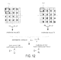
- FIG. 12 describes the calculation of the gain value.
- FIG. 13 describes the gain correction
- FIG. 14 describes the generation of temporary parallax images.
- FIG. 15 describes the calculation of the gain value.
- FIG. 16 describes the local gain correction.
- FIG. 17 describes interpolation of the G component.
- FIG. 18 describes the process of generating color parallax plane data.
- FIG. 19 shows an example of interpolation of the pixel value.
- FIG. 1 shows a configuration of a digital camera 10 , which is one aspect of an image processing apparatus and an image-capturing apparatus and is configured so that it is capable of generating in one scene a left view point image and a right view point image with a single image-capturing.
- a parallax image Each image having different viewpoints is referred to as a parallax image.
- the digital camera 10 includes an image-capturing lens 20 as an image-capturing optical system, and guides the subject light flux that is incident along an optical axis 21 thereof to an image sensor 100 .
- the image-capturing lens 20 may be an exchangeable lens that can be attached to the digital camera 10 .
- the digital camera 10 includes the image sensor 100 , a controller 201 , an A/D conversion circuit 202 , a memory 203 , a driving unit 204 , an image processor 205 , a memory card IF 207 , an operation unit 208 , a display 209 , an LCD drive circuit 210 , and an AF sensor 211 .
- a direction parallel to the optical axis 21 that extends toward the image sensor 100 is defined as the Z-axis positive direction
- a direction orthogonal to the plane of the Z-axis and moving upward from the plane of the drawing is defined as the X-axis positive direction
- a direction upward within the plane of the drawing is defined as the Y-axis positive direction.
- the X-axis is the horizontal direction
- the Y-axis is the vertical direction.
- the image-capturing lens 20 is configured by a plurality of optical lens groups, and focuses the subject light flux from a scene near the focal plane of the image-capturing lens 20 .
- the image-capturing lens 20 is represented by a single virtual lens arranged near the pupil.
- the image sensor 100 is arranged near the focal plane of the image-capturing lens 20 .
- the image sensor 100 is an image sensor, such as a CCD or CMOS sensor, in which a plurality of photoelectric converting elements is arranged two-dimensionally.
- the timing of the image sensor 100 is controlled by the driving unit 204 , and the image sensor 100 converts a subject image focused on a light receiving surface into an image signal and outputs the image signal to the A/D conversion circuit 202 .
- the A/D conversion circuit 202 converts the image signal output from the image sensor 100 into a digital image signal and outputs it to the memory 203 .
- the image processor 205 performs various types of image processing using the memory 203 as a work space to generate image data.
- the image processor 205 includes an interpolation processing unit 231 , a standard image data generating unit 232 , a filter processing unit 233 , and a parallax image data generating unit 234 .
- the interpolation processing unit 231 generates left parallax image data of a left view point and right parallax image data of a right view point based on the output of the image sensor 100 .
- the left parallax image data and the right parallax image data generated by the interpolation processing unit 231 are data used for processing by the standard image data generating unit 232 and the parallax image data generating unit 234 .
- the left parallax image data and the right parallax image data themselves generated by the interpolation processing unit 231 are not output as final left parallax image data and right parallax image data, so the left parallax image data and the right parallax image data are referred to as temporary parallax image data for generating the final parallax image data.
- the spatial frequency resolution of the left parallax image data and the right parallax image data generated by the interpolation processing unit 231 is lower than the spatial frequency resolution of the left parallax image data and the right parallax image data generated by the parallax image data generating unit 234 .
- the standard image data generating unit 232 generates standard image data using the pixel values of the left parallax image data and the right parallax image data generated by the interpolation processing unit 231 .
- the standard image data is described in detail later.
- the spatial frequency resolution of the standard image data is higher than the spatial frequency resolution of the left parallax image data and the right parallax image data generated by the interpolation processing unit 231 .
- the filter processing unit 233 carries out filtering processes to carry out edge adjustment and/or noise elimination on the standard image data generated by the standard image data generating unit 232 .
- edge enhancement is described mainly as edge adjustment.
- the parallax image data generating unit 234 uses the left parallax image data and the right parallax image data generated by the interpolation processing unit 231 and the standard image data resulting from filter processing by the filter processing unit 233 , and generates left parallax image data and right parallax image data with a higher resolution than the left parallax image data and the right parallax image data generated by the parallax image data generating unit 234 .
- the image processor 205 also undertakes general image processing such as adjusting image data in accordance with selected image formats, and the like.
- the generated image data is converted into display signals by the LCD drive circuit 210 , to be displayed on the display 209 . Also, the data is recorded on a memory card 220 provided in the memory card IF 207 .
- the AF sensor 211 is a phase difference sensor with a plurality of distance measurement points set with respect to the subject space, that detects the amount of defocus of the subject image at each of the distance measurement points.
- a series of image-capturing sequences is begun as a result of the operation unit 208 receiving user's manipulation to output a manipulation signal to the controller 201 .
- Execution of the various operations associated with the image-capturing sequence, such as AF, AE, and the like, are controlled by the controller 201 .
- the controller 201 analyzes the signal detected by the AF sensor 211 , and executes a focusing control to move a focusing lens that constitutes a portion of the image-capturing lens 20 .
- FIG. 2 is a schematic view illustrating a cross-section of the image sensor 100 .
- the image sensor 100 is formed by arranging microlenses 101 , color filters 102 , aperture masks 103 , a wiring layer 105 , and photoelectric converting elements 108 in the stated order from the subject side.
- the photoelectric converting elements 108 are each formed by a photodiode that converts the incident light into an electrical signal.
- a plurality of photoelectric converting elements 108 is arranged two-dimensionally on the surface of a substrate 109 .
- the image signal resulting from the conversion by the photoelectric converting elements 108 and the control signals for controlling the photoelectric converting elements 108 are transmitted and received by wiring 106 provided in the wiring layer 105 .
- the aperture masks 103 provided corresponding one-to-one with each of the photoelectric converting elements 108 , include aperture portions 104 arranged repetitively in a two-dimensional array and are provided in contact with the wiring layer. As described later, the aperture portions 104 are shifted in accordance with a corresponding one of the photoelectric converter elements 108 and are strictly positioned at locations relative to the corresponding photoelectric converting element 108 .
- the aperture masks 103 having aperture portions 104 function to create parallaxes in the subject light flux received by the photoelectric converting elements 108 .
- aperture mask 103 there is no aperture mask 103 positioned above the photoelectric converting elements 108 that do not cause a parallax.
- aperture masks 103 are provided including aperture portions 104 that pass all effective light, i.e. that do not limit the subject light flux incident to the corresponding photoelectric converting elements 108 .
- the aperture 107 formed by the wiring 106 substantially defines the incident subject light flux, and therefore the wiring 106 can be thought of as an aperture mask that passes all the incident light flux and does not cause a parallax.
- Each aperture mask 103 may be arranged independently in correspondence with a photoelectric converting element 108 , or the aperture masks 103 may be formed en bloc for a plurality of photoelectric converting elements 108 using the same manufacturing process as used for the color filters 102 .
- the color filters 102 are provided on the aperture masks 103 .
- the color filters 102 correspond one-to-one with the photoelectric converting elements 108 , and each color filter 102 is colorized to pass a specified wavelength band to the corresponding photoelectric converting element 108 .
- red filters (R filters) that pass a red wavelength band
- green filters (G filters) that pass a green wavelength band
- blue filters (B filters) that pass a blue wavelength band may be arranged in a grid.
- the color filters are not limited to the combination of primary colors RGB, but may be the combination of complementary color filters YCM.
- the microlenses 101 are provided on the color filters 102 .
- Each microlens 101 is a converging lens that guides a majority of the subject light flux incident thereto to the corresponding photoelectric converting element 108 .
- the microlenses 101 correspond one-to-one with the photoelectric converting elements 108 .
- Each microlens 101 preferably has the optical axis thereof shifted to guide more subject light flux to the corresponding photoelectric converting element 108 , with consideration to the relative positions of the center of the pupil of the image-capturing lens 20 and the corresponding photoelectric converting element 108 .
- the positioning of the microlenses 101 may be adjusted such that more of the specified subject light flux that is described later is incident.
- the single unit of an aperture mask 103 , a color filter 102 , and a microlens 101 provided one-to-one with each photoelectric converting element 108 is referred to as a pixel.
- a pixel including an aperture mask 103 that causes a parallax is referred to as a parallax pixel
- a pixel including an aperture mask 103 that does not cause a parallax is referred to as a non-parallax pixel.
- the effective pixel region of the image sensor 100 is approximately 24 mm by 16 mm, there may be approximately 12 million pixels.
- the microlenses 101 need not be provided. If a back-illuminated image sensor is used, the wiring layer 105 is provided on the opposite side of the photoelectric converting elements 108 . If the aperture portions 104 of the aperture masks 103 have a color component, the color filters 102 and the aperture masks 103 can be formed integrally. If only a black and white image signal is to be output, the color filters 102 are not provided.
- the aperture mask 103 and the wiring 106 are provided separately, but the wiring 106 may undertake the function of the aperture mask 103 in the parallax pixel.
- the prescribed aperture shape is formed by the wiring 106 , and the incident light is restricted by the aperture shape and only a specific partial luminous flux is guided to the photoelectric converting element 108 .
- the wiring 106 that forms the aperture shape is on the side of the wiring layer 105 closest to the photoelectric converting element 108 .
- the aperture mask 103 may be formed by a transmission prevention film provided superimposed on the photoelectric converting element 108 .
- the aperture mask 103 is a transmission prevention film formed by, for example, stacking a SiN film and a SiO 2 film in that order, and removing the region corresponding to the aperture portion 104 by etching.
- FIGS. 3A to 3C are explanatory views of the concept of defocus in a non-parallax pixel.
- an object point which is a subject
- the subject light flux that arrives at the image sensor light receiving surface through the lens pupil exhibits a steep light intensity distribution with the pixel at the corresponding image point as center.
- the subject light flux exhibits a gentler light intensity distribution on the image sensor light receiving surface compared with the case where the object point is at the focal position.
- a distribution is shown in which the pixel of the corresponding image point has a lowered output value, and more surrounding pixels have output values.
- the subject light flux exhibits a gentler light intensity distribution on the image sensor light receiving surface.
- a distribution is exhibited in which the pixel of the corresponding image point has a further lowered output value, and further more surrounding pixels have output values.
- FIGS. 4A to 4C are explanatory views of the concept of defocus in a parallax pixel.
- the parallax Lt pixel and the parallax Rt pixel receive subject light flux arriving from one of two parallax virtual pupils set symmetrically on the optical axis as a lens pupil partial region.
- the system of capturing a parallax image by receiving subject light flux arriving from different virtual pupils in a single lens pupil is referred to as the single pupil divided image-capturing system.
- the subject light flux that has passed through either of the parallax virtual pupils exhibits a steep light intensity distribution with the pixel at the corresponding image point as center. If the parallax Lt pixel is arranged near the image point, the output value corresponding to the image point will be largest, and the output values of the surrounding pixels will be greatly reduced. Also, if the parallax Rt pixel is arranged near the image point, the output value of the pixel corresponding to the image point will be largest, and the output values of the surrounding pixels will be greatly reduced.
- the peak of the light intensity distribution exhibited by the parallax Lt pixel will appear at a position separated in one direction from the pixel corresponding to the image point, and the output value will be reduced. Also, the width of the pixel having that output value will be increased. The peak of the light intensity distribution exhibited by the parallax Rt pixel will appear at a position shifted in the opposite direction and an equal distance to that of the parallax Lt pixel from the pixel corresponding to the image point, and the output value will likewise be reduced.
- FIGS. 5A and 5B The variations in the light intensity distributions described in FIGS. 3A to 3C and the variations in the light intensity distributions described in FIGS. 4A to 4C are respectively represented by graphs in FIGS. 5A and 5B .
- the horizontal axis represents the pixel position, and the center position is the position of the pixel corresponding to the image point.
- the vertical axis represents the output value of each pixel. These output values are substantially proportional to the light intensity, so in this drawing, the vertical axis is labeled as the light intensity.
- FIG. 5A is a graph showing the variation in the light intensity as described in FIGS. 3A to 3C .
- the distribution curve 1801 represents the light intensity distribution corresponding to FIG. 3A , and exhibits the steepest form.
- the distribution curve 1802 represents the light intensity distribution corresponding to FIG. 3B
- the distribution curve 1803 represents the light intensity distribution corresponding to FIG. 3C . It can be seen that compared with the distribution curve 1801 , the peak values are gradually reduced, and the form becomes broader.
- FIG. 5B is a graph showing the variation in the light intensity as described in FIGS. 4A to 4C .
- the distribution curve 1804 and distribution curve 1805 represent the light intensity distribution of the parallax Lt pixel and the light intensity distribution of the parallax Rt pixel respectively of FIG. 4B .
- these distributions have a line symmetric shape about the center position.
- the composite distribution curve 1806 obtained by adding these has a similar shape to the distribution curve 1802 of FIG. 3B which has the same state of defocus as FIG. 4B .
- the distribution curve 1807 and distribution curve 1808 represent the light intensity distribution of the parallax Lt pixel and the light intensity distribution of the parallax Rt pixel respectively of FIG. 4C . As can be seen from these graphs, these distributions also have a line symmetric shape about the center position. Also, the composite distribution curve 1809 obtained by adding these has a similar shape to the distribution curve 1803 of FIG. 3C which has the same state of defocus as FIG. 4C .
- FIGS. 6A to 6D are explanatory views of the aperture shape of the aperture portion 104 in a case where there are two types of parallax pixels.
- FIG. 6A shows an example in which the shape of the aperture portion 104 l of the parallax Lt pixel and the shape of the aperture portion 104 r of the parallax Rt pixel each have the same shape as the shape of an aperture portion 104 n of a non-parallax pixel divided at the center line 322 .
- FIG. 6A shows an example in which the shape of the aperture portion 104 l of the parallax Lt pixel and the shape of the aperture portion 104 r of the parallax Rt pixel each have the same shape as the shape of an aperture portion 104 n of a non-parallax pixel divided at the center line 322 .
- the area of the aperture portion 104 n of the non-parallax pixel is equal to the sum of the areas of the aperture portion 104 l of the parallax Lt pixel and the aperture portion 104 r of the parallax Rt pixel.
- the aperture portion 104 n of the non-parallax pixel is referred to as a fully open aperture, and the aperture portion 104 l and the aperture portion 104 r are referred to as half open apertures. Also, if the aperture is positioned in the center of the photoelectric converting element, the aperture is said to be facing the standard direction.
- the aperture portion 104 l of the parallax Lt pixel and the aperture portion 104 r of the parallax Rt pixel are displaced in opposite directions about a virtual center line 322 passing through the center (pixel center) of their corresponding photoelectric converting elements 108 . Therefore, the aperture portion 104 l of the parallax Lt pixel and the aperture portion 104 r of the parallax Rt pixel produce parallax with respect to the standard direction in one direction, and the other direction that is opposite to the one direction, respectively.
- FIG. 6B shows the light intensity distribution for a case in which an object point is shifted from the focal position, when each of the pixels has the apertures shown in FIG. 6A .
- the curve Lt corresponds to the distribution curve 1804 of FIG. 5B
- the curve Rt corresponds to the distribution curve 1805 of FIG. 5B .
- the curve N corresponds to a non-parallax pixel, and it has a similar shape to the composite distribution curve 1806 of FIG. 5B .
- each of the aperture portions 104 n , aperture portions 104 l , and aperture portions 104 r has a function of the aperture diaphragm.
- the width of blurring of the non-parallax pixel having the aperture portion 104 n whose area is double of the aperture portion 104 l is about the same as the width of the blurring of the curve that is the sum of the parallax Lt pixel and the parallax Rt pixel and is indicated by the composite distribution curve 1806 of FIG. 5B .
- FIG. 6C shows an example in which the shape of the aperture portion 104 l of the parallax Lt pixel, the shape of the aperture portion 104 r of the parallax Rt pixel, and the shape of the aperture portion 104 c of the parallax C pixel are each the same shape.
- the parallax C pixel is referred to as a pixel with no eccentricity.
- the parallax C pixel is strictly a parallax pixel that outputs a parallax image in that it guides only the subject light flux from the partial region at the center portion of the pupil to the photoelectric converting element 108 .
- a pixel having an aperture corresponding to the standard direction is defined as a non-parallax pixel.
- the parallax C pixel of FIG. 6C having its aperture in the center of the photoelectric converting element similar to the non-parallax pixel of FIG. 6A as the standard direction is a non-parallax pixel.
- the aperture portion 104 l , the aperture portion 104 r , and the aperture portion 104 c have half the area of the aperture portion 104 n shown in FIG. 6A .
- Both the aperture portion 104 l and the aperture portion 104 r touch the virtual center line 322 that passes through the center (pixel center) of the photoelectric converting element 108 , the same as in FIG. 6A .
- FIG. 6D shows the light intensity distribution for a case in which an object point is shifted from the focal position, when each of the pixels has the apertures shown in FIG. 6C .
- the curve Lt corresponds to the distribution curve 1804 of FIG. 5B
- the curve Rt corresponds to the distribution curve 1805 of FIG. 5B .
- each of the aperture portions 104 c , aperture portions 104 l , and aperture portions 104 r has a function of the aperture diaphragm.
- the width of blurring of the parallax C pixel which has the aperture portion 104 c with the same shape and same area as the aperture portion 104 l and the aperture portion 104 r , is about the same as the width of blurring of the parallax Lt pixel and the parallax Rt pixel.
- the parallax is included in the blurring, and an optical image is obtained at the focal position that is the same as 2D image-capturing.
- Patent Document 1 a color and parallax array including a combination of an array of color filters and left and right parallax pixels only is disclosed.
- the color and parallax array disclosed in Patent Document 1 There is no limitation to the color and parallax array disclosed in Patent Document 1.
- color and parallax arrays in which non-parallax pixels are arranged can also be used.
- image-capturing by these color and parallax arrays is referred to as stereoscopic image-capturing by the single pupil divided image-capturing system.
- generating a left parallax image by gathering the sampling points (lattice points) of the left parallax pixels only and interpolating the empty lattice points, and generating a right parallax image by collecting the sampling points of the right parallax pixels and interpolating the empty lattice points, by the image processor 205 can be considered.
- the problem that it is not possible to obtain a resolution that exceeds the sampling resolution limit of the respective parallax pixels inevitably remains.
- this 2D intermediate image can have a resolution capability up to the Nyquist frequency, which is equal to the resolution limit when all pixels are sampled under constant conditions.
- an inherent characteristic of the single pupil divided image-capturing system is that the point spread function of the subject image at the focus position is the same point spread function for non-parallax pixels, left parallax pixels, and right parallax pixels. Therefore, near the focus position, a subject image is taken that is the same as that of a 2D dedicated sensor, and its resolution can be derived to the maximum extent.
- a problem to be aware of here is that if the high resolution left parallax image and the high resolution right parallax image obtained by parallax modulation form an unfocused region subject image that has shifted from the focus position, then even though the high frequency resolution of the 2D intermediate image is reflected, the high frequency component above the resolution limit in the original low resolution left parallax image and low resolution right parallax image appear as low frequency Moire fringes. On the other hand, in the 2D intermediate images, this Moire component does not appear even in the unfocused region. In other words, a stable high resolution can be achieved in the 2D intermediate images.
- edge enhancement processing is not carried out individually for the left parallax image and the right parallax image, but edge enhancement processing is carried out on the 2D image after first generating the high-resolution 2D intermediate image. Then, the 3D image on which the edge enhancement process has been performed is generated by adding parallax modulation.
- this image processing procedure is carried out, aliasing and Moire fringes which exceed the sampling limit of the parallax pixels are not enhanced, but it is possible to obtain a high definition natural edge enhanced stereoscopic image.
- FIG. 7 shows a Bayer type G parallax pixel array and the resolution of the array in frequency space.
- the color filter array has a Bayer array structure in which a left aperture parallax pixel is provided on one G pixel, and a right aperture parallax pixel is provided on another G pixel as the aperture mask.
- fully open non-parallax pixels are provided for the R pixels and the B pixels. This corresponds to the array described in Embodiment 1 which is described later.
- FIG. 7 shows a frequency space diagram (k-space diagram) representing the sampling resolution limit corresponding to each parallax and each color component.
- a 2D intermediate image as described previously is generated for a monochrome subject (for example, a circular zone plate) in the focus position, resolution is obtained to the Nyquist frequency limit of the outermost side.
- the resolution frequency is basically limited to a rectangular region on the inside.
- FIGS. 8A to 8C are explanatory views of Moire fringes in parallax images.
- FIG. 8A shows a non-parallax image
- FIG. 8B shows a left parallax image
- FIG. 8C shows a right parallax image.
- the images shown in FIGS. 8B and 8C are generated by the process described later in Embodiment 1 excluding the edge enhancement process part.
- a 3D image is obtained via a 2D intermediate image of a subject that is shifted a little from the focus position described above, as shown in FIGS. 8B and 8C , a Moire component appears on the left and right parallax images associated with the sampling limit of the parallax images.
- edge enhancement is carried out separately for the left parallax pixel and the right parallax pixel, the Moire component of spurious resolution is emphasized, which harms the image quality. If edge enhancement of the 2D intermediate image is carried out, a high definition 3D edge enhancement process can be carried out that does not enhance the Moire component.
- arrays can be used as color and parallax arrays with mixed left parallax pixels (Lt), right parallax pixels (Rt), and non-parallax pixels (N).
- Lt left parallax pixels
- Rt right parallax pixels
- N non-parallax pixels
- an array with a low density of parallax pixels as described later in Embodiment 2 and an array with a low density of parallax pixels and a monochrome array as described later in Embodiment 3 can be used.
- high resolution 2D intermediate images are generated, and the generated 2D intermediate image is superimposed on the 3D image to obtain high resolution output images for both 2D and 3D images.
- the color information of the parallax pixels and the non-parallax pixels are mutually referenced and a way of utilizing this correlation is introduced.
- noise elimination filter With a noise elimination filter, the higher the resolution of an image, the higher the accuracy with which a region in which the edge structure must be kept can be determined. As a result, in a region where the edge structure must be kept, it becomes difficult to eliminate information regarding the image structure. Therefore, it is desirable to carry out a noise elimination process on the high resolution 2D intermediate image, the same as for edge enhancement.
- a commonly known edge-preserving smoothing filter can be used as the filter.
- a fluctuating noise component appears in both the temporarily interpolated low resolution left parallax image and the right parallax image.
- the fluctuating noise component is removed from the low resolution left parallax image and the right parallax image at the stage prior to carrying out parallax modulation.
- Embodiment 2 and Embodiment 3 which are described later, the number of non-parallax pixels is largest, and the sparse parallax pixels are present only in intermittent locations. Therefore, the images have the special property that the interpolation values calculated by average interpolation between these points do not include the original high frequency noise component. Therefore, in the case of a sparse parallax pixel array, for a commonly used high sensitivity region of ISO800 or ISO6400, a noise elimination process may be carried out on the intermediate 2D image only. This is described in detail later in Embodiment 4. In a very high sensitivity region of ISO12800 to ISO409600, this fluctuating component is prominent even with sparse parallax pixels. Therefore, it is necessary to remove the fluctuating component.
- the process to remove the fluctuating component need not be carried out on all the pixels at the actual resolution.
- the actual resolution may be restored by a variable magnification process and just a subtraction process may be carried out.
- the multiple resolution noise elimination technology disclosed in Japanese Unexamined Patent Application Publication No. 2006-309749A of the same inventor as the present application can be used.
- a process may be carried out in which multiple resolution conversion is carried out sequentially reducing from high-resolution to low-resolution and at each resolution the noise component is extracted, and these are successively integrated to restore the noise component at the actual resolution, so several stages on the high-resolution side may be omitted. Therefore, for a temporarily interpolated parallax image, all the high resolution side processing, which requires the largest scale of computing in the noise elimination process, may be omitted. Therefore, calculation can be performed that is extremely convenient, in other words, at a high speed in the case of software, and with a small circuit scale in the case of hardware.
- the image processing procedure is generally as follows.
- the gradation is a linear gradation output by A/D conversion.
- the pixel values are proportional to the amount of light. This may also be referred to as raw data.
- the aperture diaphragm is narrowed, the greater not only the difference in the relative distribution between left and right, but also the difference in the average signal level of the whole image produces a problem, for the luminous intensity of the left parallax pixel and the luminous intensity of the right parallax pixel, so at this stage, a gain correction is carried out to adjust the overall brightness. Therefore, using the captured subject image as it is, the average value L t of the pixel value of the left parallax pixels for the whole image and the average value R t of the pixel value of the right parallax pixels for the whole image are calculated.
- the signal plane of the left parallax pixel of the G component is taken to be Lt mosaic (x, y), and the signal plane of the right parallax pixel of the G component is taken to be Rt mosaic (x, y).
- the arithmetic average is adopted.
- the mosaic image that has been corrected with a single gain coefficient for the left parallax pixels and a single gain coefficient for the right parallax pixels is output as M′(x, y).
- This step can be executed simultaneously with the local gain correction carried out in step 4, so in some cases, it may be omitted.
- a left parallax image and a right parallax image with low spatial frequency resolution capability are generated.
- a simple average interpolation within the G color plane in which only the left parallax pixels are gathered is carried out. Using the pixel values of the adjacent pixels, linear interpolation is carried out in accordance with the ratio of distance. Likewise, simple average interpolation within the G color plane in which only the right parallax pixels are gathered is carried out. In other words, from Lt mosaic (x, y), Lt(x, y) is generated, and from Rt mosaic (x, y), Rt(x, y) is generated.
- the brightness of the left parallax pixels within the screen and the right parallax pixels within the screen are adjusted by carrying out local gain correction on pixel units, by the same concept as the global gain correction carried out in step 1.
- a new Bayer plane is produced with adjusted gain. This is equivalent to replacing with average values to create a Bayer plane with the parallax eliminated. This is written as M N (x, y).
- the process of applying the local gain correction to each pixel may be just substituting the average value for each pixel actually initially obtained. What this means is that the local gain correction is a modulation process for eliminating parallax.
- the arithmetic average is adopted. In this way, the no-parallax Bayer plane image M N (x, y) is output by converting the Bayer plane data in such a manner that the average value between the left and right viewpoint images is used as the no-parallax pixel value of the new G pixel position.
- Interpolation values are predicted in gamma space (image processing space) for interpolation by gradation conversion to realize a more uniform noise space, with the objective of carrying out the high resolution Bayer interpolation as described above.
- This method is introduced in U.S. Pat. No. 7,957,588 of the same inventor as the present application.
- the input signal is denoted by x and the output signal is denoted by y, the gradation of the input signal and the gradation of the output signal are both defined in a range [0, 1].
- the positive offset value s is set to a larger value, the higher the sensitivity of the image-capturing conditions in which the dark current noise component increases.
- step S 4 the CPU carries out the interpolation process as follows.
- the pixel having the color information of the R component is referred to as the R pixel
- the pixel having the color information of the B component is referred to as the B pixel
- the pixel having the color information of the G component is referred to as the G pixel
- the signal value of the R component corresponding to the pixel indicated by the pixel position [i, j] in the interpolation process is represented as R[i, j]
- the signal value of the G component is represented as G[i, j]
- the signal value of the B component is represented as B[i, j].
- the CPU calculates the vertical direction degree of similarity CvN[i, j] and the horizontal direction degree of similarity ChN[i, j] from the following equations (3) and (4).
- Z[i, j] is the signal value of the R component or the B component indicated by the pixel position [i, j].
- the first term is the degree of similarity between the same color representing the degree of similarity between the same color of 2 pixel interval
- the second term is the degree of similarity between different colors representing the degree of similarity between different colors of adjacent pixel intervals.
- the degree of similarity between different colors has the capacity to resolve the vertical and horizontal Nyquist frequency.
- the absolute value of the first term detects the general direction by comparing G color components.
- the absolute values of the second term and the third term of the above equations (3) and (4) detect the detailed similarity that cannot be detected with the first term.
- the CPU calculates for each coordinates the degree of similarity in the vertical direction and the degree of similarity in the horizontal direction obtained from the above equations (3) and (4), and determines the direction of the similarity from equation (5) based on the vertical and horizontal degrees of similarity at the target coordinates [i, j].
- Th is a determination threshold value used for the purpose of avoiding erroneous determination due to noise included in the signal value, and varies in accordance with the ISO sensitivity described above.
- the CPU interpolates the G component using the unevenness information of the R component or the B component.
- the CPU interpolates the G component using the unevenness information of the R component or the B component.
- the information on the high frequency component obtained by sampling the other color components is superimposed onto the interpolation target color component.
- G color supplementation is calculated in the case of vertical direction similarity from the equations (6) and (9) for the position [i, j] of the center of the R pixel indicated in FIG. 4 of WO2006/006373, for example, and in the case of horizontal direction similarity is calculated from equations (7) and (10).
- the pixel position in the case of G color interpolation for the position of the B pixel is shown in FIG. 5 of WO2006/006373.
- Z[i, j] is the signal value of the R component or the B component indicated by the pixel position [i, j]. Adding the second order differential correction term due to the other color components of the second term to the average value of the color component of the interpolation target of the first term has the action of increasing the spatial resolution capability in the inclined directions.
- the first term in equation (9) represents the average value calculated from the signal values G[i, j ⁇ 1] and G[i, j+1] of the G components aligned vertically with respect to the pixel position [i, j].
- the second term in equation (9) represents the amount of change calculated from the signal values R[i, j], R[i, j ⁇ 2], and R[i, j+2] of the R components aligned vertically.
- Equation (10) above carries out extrapolation interpolation in the horizontal direction using the signal values of the pixels aligned horizontally with respect to the pixel position [i, j], in the same way as the extrapolation interpolation in the vertical direction as described above. If the similarity directions are classified as both the vertical and horizontal directions, the CPU calculates the G color interpolation values from the above equations (9) and (10), and takes the average of the two calculated G color interpolation values as the G color interpolation value.
- R color interpolation is calculated from the equations (11) to (13) for pixel positions [i+1, j], [i, j+1], [i+1, j+1] other than the position [i, j] of the R pixel shown in FIG. 6 of WO2006/006373, for example.
- the unevenness information of the G component signal values (FIG. 7 of WO2006/006373) corresponding to all the pixel positions obtained by G interpolation as described above is used.
- R[i +1, j ] ( R[i,j]+R[i +2, j ])/2+(2 ⁇ G[i +1, j] ⁇ G[i,j] ⁇ G[i +2, j ])/2 (11)
- R[i,j+ 1] ( R[i,j]+R[i,j +2])/2+(2 ⁇ G[i,j +1 ] ⁇ G[i,j] ⁇ G[i,j +2])/2
- R[i +1, j +1] ( R[i,j]+R[i +2, j]+R[i,j +2 ]+R[i +2, j +2])/4+(2 ⁇ G[i +1, j +1 ] ⁇ G[i,j] ⁇ G[i +2, j] ⁇ G[i,j +2 ] ⁇ G[i +2, j +2])/4 (13)
- the first term in the above equations (11) to (13) represents the average value calculated from the R component signal values adjacent to the coordinates of the target of the R component interpolation
- the second term in the above equations (11) to (13) represents the amount of variation calculated from the G component signal values of the coordinates of the target of the R component interpolation and the adjacent coordinates.
- B component interpolation is carried out by the same interpolation process as for the R component. For instance, pixel positions [i+1, j], [i, j+1], [i+1, j+1] other than the position [i, j] of the B pixel indicated in FIG. 8 of WO2006/006373 are calculated using equations (14) to (16). At this time, the unevenness information of the G component signal values (FIG. 9 of WO2006/006373) corresponding to all of the pixel positions obtained in the G interpolation as described above is used.
- the sampling frequency of the R component and the B component is low compared with the G component, so the high frequency component of the G component signal value is reflected using the color difference R-G, and the color difference B ⁇ G. Therefore, interpolation of this type of chromatic component is referred to for convenience as color difference interpolation.
- the RGB color images with no parallax obtained by the Bayer interpolation in step 5 are represented as R N ⁇ (x, y), G N ⁇ (x, y), and B N ⁇ (x, y). These are the RGB data representing the gradation in the interpolation gamma space. These RGB data are converted into the color coordinate system YCbCr which represents brightness and color differences.
- ⁇ represents a Laplacian filter representing second-order differentiation.
- the constant k is a parameter for adjusting the extent of edge enhancement.
- the following filter coefficients can be considered as the Laplacian filter, but this is not a limitation.
- the RGB space is restored from the YCbCr space. All that is necessary is to multiply by the inverse matrix of step 6-1).
- the definition is the same as that adopted for JPEG, so its description is omitted here.
- step 5-1 The inverse gradation conversion of step 5-1 is carried out on each of the RGB color planes for which Bayer interpolation and edge enhancement processing has been carried out, to restore the linear relation RGB data.
- the RGB color images with no parallax obtained in this way are represented as R N (x, y), G N (x, y), and B N (x, y). These are the RGB data represented by linear gradation.
- Two methods can be considered for the method of parallax modulation: the method using the arithmetic average as the reference point; and the method using the geometric average as a reference point. Both methods are capable of obtaining the parallax modulation effect, but the method using the arithmetic mean as the reference point may be adopted when the aperture mask of the non-parallax pixel of the image sensor is fully open, and the method of using the geometric average as the reference point may be adopted when the aperture mask of the non-parallax pixel is half open, the same as the pixel with parallax. Therefore, in this embodiment, the method of using the arithmetic average as a reference point is used.
- R Lt ⁇ ( x , y ) R N ⁇ ( x , y ) ⁇ 2 ⁇ Lt ⁇ ( x , y ) Lt ⁇ ( x , y ) + Rt ⁇ ( x , y )
- G Lt ⁇ ( x , y ) G N ⁇ ( x , y ) ⁇ 2 ⁇ Lt ⁇ ( x , y ) Lt ⁇ ( x , y ) + Rt ⁇ ( x , y )
- B Lt ⁇ ( x , y ) B N ⁇ ( x , y ) ⁇ 2 ⁇ Lt ⁇ ( x , y ) Lt ⁇ ( x , y ) + Rt ⁇ ( x , y )
- step 7 modulation is carried out by multiplying terms that are in an exact inverse proportional relationship between the parallax modulation calculation equation defined in step 7 and the parallax elimination calculation equation for correcting brightness unevenness between left and right (local gain balance correction) defined in step 4. Therefore, in step 7, modulation acts on the direction of adding parallax, and in step 4, modulation acts on the direction of eliminating parallax.
- Each of the high-resolution intermediate color images with no parallax R N (x, y), G N (x, y), B N (x, y), the high resolution left parallax color images R Lt (x, y), G Lt (x, y), B Lt (x, y), and the high resolution right parallax color images R Rt (x, y), G Rt (x, y), B Rt (x, y) obtained in this way are converted into the standard sRGB color space from the camera RGB with sensor spectral properties by color matrix conversion and gamma conversion to output the images as output color space images.
- edge enhanced high definition 2D images and 3D images are generated.
- FIG. 11 shows an example of a repeating pattern 110 in the case that there are two types of parallax pixels.
- the coordinate system of the digital camera 10 has been defined as the X axis, the Y axis, and the Z axis, in the image sensor 100 , the right direction is defined as the X axis, and the downward direction is defined as the Y axis, with reference to the left most and uppermost pixel.
- the four pixels are adopted as the repeating pattern 110 , the same as for the Bayer array.
- This repeating pattern 110 is arranged periodically top to bottom and left to right in the effective pixel area of the image sensor 100 .
- the image sensor 100 uses the repeating pattern 110 indicated by the thick line in the drawing as a primitive lattice.
- the R pixel and the B pixel are non-parallax pixels, the Gb pixel is allocated as a parallax L pixel, and the Gr pixel is allocated as a parallax R pixel.
- the aperture portion 104 is defined so that the parallax Lt pixel and the parallax Rt pixel included in the same repeating pattern 110 receive the light flux irradiated from the same micro region.
- the non-parallax pixel has an aperture portion that is fully open, and the parallax Lt pixel and the parallax Rt pixel have an aperture portion that is half open.
- the pixel pitch is taken to be “a”.
- the Gb pixel and the Gr pixel which are green pixels with high luminosity factor are used as parallax pixels, so parallax images with high contrast can be expected to be obtained.
- the Gb pixel and the Gr pixel which are the same green pixels are used as parallax pixels, so a conversion calculation to an output with no parallax can be easily carried out from these two outputs, so the R pixel and the B pixel which are non-parallax pixels can be output, and it is possible to generate high image quality 2D image data.
- FIG. 7 shows the resolution capability regarding the spatial frequency of images captured by the image sensor that adopts the repeating pattern 110 shown in FIG. 11 .
- f represents frequency.
- the frequency resolution region is described by the first Brillouin zone representing a unit cell (Wigner-Seitz cell) of the reciprocal lattice space.
- the range enclosed by the dotted line is the limiting resolution frequency of the image.
- the color filter and the aperture mask are arranged superimposed on a single sensor surface. The information that can be taken on a single sensor surface is constant, so the amount of information is reduced by dividing the function.
- the relative number of non-parallax pixels is reduced, so the amount of information that can be obtained by the non-parallax pixels is reduced.
- the color filter by just dividing into the three R, G, and B, the individual amounts of information are reduced.
- the intermediate view point R component image with no parallax R N and the intermediate view point B component image with no parallax B N .
- Each of the pixels in the pixel array shown in FIG. 11 is characterized by various combinations of parallax pixels and non-parallax pixels focused on the aperture portion 104 , and R pixels, G pixels, and B pixels focused on the color filter 102 . Therefore, if the output of the image sensor 100 is brought into coincidence with this pixel array and enumerated as it is, image data representing a specific image will not be obtained. In other words, only if the pixel output of the image sensor 100 is divided into pixel groups each having the same characteristics and brought together, image data representing a single image in accordance with these characteristics is formed.
- parallax image data For example, if the output of a parallax pixel is brought together with its type of aperture portion, a plurality of pieces of parallax image data can be obtained each having a parallax.
- the image data for each pixel group having the same characteristics that are separated and brought together is referred to as plane data.
- the interpolation processing unit 231 of the image processor 205 receives mosaic image data M mosaic (x, y) which is raw original image data enumerating the output values in the order of the pixel array of the image sensor 100 .
- a mosaic image refers to an image in which each pixel is lacking information on at least one of R, G, and B, and the data forming a mosaic image is referred to as mosaic image data.
- each pixel is lacking information on at least one of R, G, and B, if it cannot be treated as the image, for example, if the image data is composed of pixel values of pixels with a single color, it cannot be treated as a mosaic image.
- Each output value is a linear gradation value proportional to the amount of light received by each of the photoelectric converting elements of the image sensor 100 .
- the interpolation processing unit 231 of the image processor 205 carries out gain correction in order to coordinate the overall brightness between left and right at this stage. This is because the more the aperture diaphragm is narrowed, the greater the difference produced not only in the relative distribution between left and right, but also in the average signal level of the overall image, for the luminous intensity of the light incident on the left parallax pixel and the luminous intensity of the light incident on the right parallax pixel.
- the gain correction to coordinate the overall brightness between left and right is referred to as the global gain correction.
- FIG. 12 describes the calculation of the gain value.
- the G component left parallax pixel mosaic image data is represented as Lt mosaic (x, y)
- the G component right parallax pixel mosaic image data is represented as Rt mosaic (x, y)
- FIG. 12 only to the left and right parallax pixels are extracted and shown.
- the types of pixels in accordance with the example of FIG. 11 are shown for ease of understanding, but actually the output values are arranged in accordance with each pixel.
- FIG. 13 describes the gain correction.
- the interpolation processing unit 231 of the image processor 205 calculates the gain values for the left and right parallax pixels
- gain correction is carried out using the calculated gain value for each pixel of the Lt mosaic (x, y) and the Rt mosaic (x, y). Specifically, the gain correction is applied to the left parallax pixel in accordance with the following (Formula 1), and the gain correction is applied to the right parallax pixel in accordance with (Formula 2).
- the G component left parallax pixel mosaic image data is represented as Lt′ mosaic (x, y)
- the G component right parallax pixel mosaic image data is represented as Rt′ mosaic (x, y).
- the interpolation processing unit 231 of the image processor 205 can generate the mosaic image data M′ mosaic (x, y) in which the left parallax pixels and the right parallax pixels within the M mosaic (x, y) have been corrected each with a single gain coefficient.
- the interpolation processing unit 231 of the image processor 205 generates a left parallax image and a right parallax image with low spatial frequency resolution, as temporary parallax images.
- FIG. 14 describes the generation of the temporary parallax images.
- the interpolation processing unit 231 of the image processor 205 first separates the mosaic image data M′ mosaic (x, y) into a plurality of plane data. At this time, there are output values in each of the plane data only at pixel positions where there are output values in the raw original image data. Therefore, the interpolation processing unit 231 of the image processor 205 carries out interpolation processing based on each of the plane data, to generate plane data in which the empty lattices are filled.
- the left side of the top shows the plane data Lt′ mosaic (x, y) in which the left parallax pixels only have been extracted from the mosaic image data M′ mosaic (x, y), and the right side shows the plane data Rt′ mosaic (x, y) in which only the right parallax pixels have been extracted from the mosaic image data M′ mosaic (x, y).
- Lt′ mosaic x, y
- Rt′ mosaic x, y
- the interpolation processing unit 231 of the image processor 205 calculates in an interpolation process the pixel values of the empty lattices using the pixel values of the nearby left parallax pixels. For example, the pixel value of the empty lattice P L1 is calculated by calculating the average of the pixel values of the adjacent four left parallax pixels in the diagonal directions.
- the interpolation processing unit 231 of the image processor 205 By carrying out the interpolation process by calculating the average of the pixel values of the nearby left parallax pixels for all of the empty lattices, the interpolation processing unit 231 of the image processor 205 generates the plane data Lt′(x, y) in which the empty lattices are filled, as shown in the bottom left of FIG. 14 .
- the interpolation processing unit 231 of the image processor 205 may carry out additional interpolation processing using the pixel values calculated in the interpolation process, and may carry out interpolation processing using only the output values that exist at the stage of the raw original image data.
- the interpolation processing unit 231 of the image processor 205 calculates in the interpolation process the pixel values of the empty lattices using the pixel values of the nearby right parallax pixels. For example, the pixel value of the empty lattice P R1 is calculated by calculating the average of the pixel values of the adjacent four right parallax pixels in the diagonal directions.
- the interpolation processing unit 231 of the image processor 205 By carrying out the interpolation process by calculating the average of the pixel values of the nearby right parallax pixels for all of the empty lattices, the interpolation processing unit 231 of the image processor 205 generates the plane data Rt′(x, y) in which the empty lattices are filled, as shown in the bottom right of FIG. 14 .
- the standard image data generating unit 232 of the image processor 205 carries out gain correction for each pixel of Lt′(x, y) using their respective calculated gain values, and likewise carries out gain correction for each pixel of Rt′(x, y) using their respective calculated gain values. In this way, the brightness of the left parallax pixels and the right parallax pixels in the same pixel position are adjusted.
- gain correction carried out in this way using the gain values calculated in pixel units is referred to as local gain correction, in contrast to the global gain correction as described above.
- FIG. 15 describes the calculation of the gain value.
- the standard image data generating unit 232 of the image processor 205 calculates the average value of each pixel from Lt′(x, y) and Rt′(x, y).
- the arithmetic average is adopted in order that the width of blurring of the subject image in the G component non-parallax pixels from which the parallax has been eliminated is matched with the width of blurring of the subject image of the non-parallax pixels.
- the standard image data generating unit 232 of the image processor 205 calculates the average value from the following (Formula 3).
- FIG. 16 describes the local gain correction.
- the standard image data generating unit 232 of the image processor 205 can carry out the local gain correction by just replacing each of the pixel values of the left and right parallax pixels of the repeating pattern 110 with the m(x m , y n ), and m(x m+1 , y n+1 ) calculated from (Formula 3).
- the local gain correction is a modulation process for eliminating parallax.
- the standard image data generating unit 232 of the image processor 205 generates the M N (x, y) by replacing all the pixel values of the left and right parallax pixels with the corresponding average values calculated from (Formula 3).
- the local gain correction does not have to be carried out on all the pixels of Lt′(x, y) and Rt′(x, y), and it may be carried out on the pixels corresponding to the positions of the left parallax pixels and the right parallax pixels in the Bayer array.
- the standard image data generating unit 232 of the image processor 205 generates color image data with no parallax having resolution capability to the Nyquist frequency of each pixel from the M N (x, y) as the intermediate image data.
- FIG. 17 describes interpolation of the G component.
- G color interpolation is calculated for the center R pixel position [i, j] shown on the left of FIG. 17 , with reference to the pixels in the drawing.
- the pixel positions in the case of G color interpolation for the positions of the B pixels are shown in the right of FIG. 17 .
- the filter processing unit 233 of the image processor 205 carries out edge enhancement processing on the intermediate image data.
- the parallax image data generating unit 234 of the image processor 205 uses the five plane data Lt′(x, y), Rt′(x, y), R N (x, y), G N (x, y), and B N (x, y) to generate the left side view point color image data and right side view point color image data.
- the parallax image data generating unit 234 of the image processor 205 generates left and right color image data by superimposing the parallax components of the temporary parallax images on the images with no parallax. This generating process is referred to as the parallax modulation process.
- the left side view point color image data is configured from the three color parallax plane data: the red plane data R Lt (x, y), the green plane data G Lt (x, y), and the blue plane data B Lt (x, y), corresponding to the left side view point.
- the right side view point color image data is configured from the three color parallax plane data: the red plane data R Rr (x, y), green plane data G Rr (x, y), and blue plane data B Rt (x, y), corresponding to the right side view point.
- FIG. 18 describes the process of generating color parallax plane data.
- it shows the process of generating the red parallax plane data R Lt (x, y) and R Rr (x, y) from among the color parallax plane data.
- the digital camera 10 of this embodiment by carrying out edge enhancement on high resolution 2D intermediate images with no parallax, it is possible to carry out the edge enhancement with the high frequency components of the parallax image actually resolved as high frequency resolution, without enhancing the Moire component (aliasing) in the stereoscopic image.
- a noise elimination effect with high edge preserving performance can be obtained. It is possible to reduce the affect of Moire fringes associated with the density of sampling of parallax pixels, so it is possible to avoid the defect that a significant inconsistency such as a mismatch between the same subject image appears between a plurality of parallax images.
- the top level of FIG. 9 shows an example using periodically arranged image sensors, as a primitive lattice.
- the frequency resolution region of the reciprocal lattice space also shows the combinations of each color and each parallax.
- This array is an image sensor having a structure with the properties that parallax is only produced in the blurred subject region of a single pupil divided system, the density of the parallax pixels is in a sparse arrangement, and the remaining pixels are allocated to non-parallax pixels as much as possible.
- the emphasis is more on the resolution capability of the intermediate images with no parallax that capture the original signal than in Embodiment 1, and it is possible to obtain a high resolution stereoscopic image by superimposing the high frequency component on the left parallax image and the right parallax image by parallax modulation. Therefore, this is a color and parallax array having the capability to provide high resolution 2D images and 3D images also in the unfocused region.
- Embodiment 1 The image processing procedures are the same as Embodiment 1. The following is a description of the procedure.
- the gradation is a linear gradation output by A/D conversion.
- the average value N of the pixel values of the non-parallax pixels of the whole image, the average value L t of the pixel values of the left parallax pixels for the whole image, and the average value R t of the pixel values of the right parallax pixels for the whole image are calculated.
- gain correction is carried out to adjust the signal level to the average value as the reference point between left and right.
- two methods can be considered for obtaining the reference point: the arithmetic average and the geometric average.
- the signal plane of the R component non-parallax pixels is represented as R N _ mosaic (x, y),
- R Rr _ mosaic (x, y)
- the signal plane of the G component non-parallax pixels is represented as G N _ mosaic (x, y),
- the signal plane of the B component non-parallax pixels is represented as B N _ mosaic (x, y),
- the signal plane of the B component left parallax pixels is represented as B Lt _ mosaic (x, y), and
- the signal plane of the B component right parallax pixels is represented as B Rt _ mosaic (x, y).
- m _ R R _ N ⁇ R _ Lt + R _ Rt 2
- m _ G G _ N ⁇ G _ Lt + G _ Rt 2
- m _ B B _ N ⁇ B _ Lt + B _ Rt 2
- g _ G N m _ G
- G _ N G _ Lt ⁇ G _ Rt G _ N
- the arithmetic average method is adopted when all the non-parallax pixels have a fully open mask.
- the geometric average method is adopted when all the non-parallax pixels have a half open mask. Therefore, in this embodiment, the arithmetic average method is adopted. In this way, the mosaic image M′(x, y) that has been corrected with a single gain coefficient for the non-parallax pixels, a single gain coefficient for the left parallax pixels, and a single gain coefficient for the right parallax pixels is output.
- a temporary left parallax image and a temporary right parallax image with low spatial frequency resolution capability are generated.
- a simple average interpolation within the G color plane in which only the left parallax pixels are gathered is carried out. Using the pixel values of the adjacent pixels, linear interpolation is carried out in accordance with the ratio of distance. Likewise, simple average interpolation within the G color plane in which only the right parallax pixels are gathered is carried out. Likewise, simple average interpolation within the G color plane in which only the non-parallax pixels are gathered is carried out. A similar process is carried out for each of R, G, and B.
- R Lt _ mosaic (x, y) is generated, from R Rt _ mosaic (x, R Rt (x, y) is generated, from R N _ mosaic (x, y), R N (x, y) is generated, from G Lt _ mosaic (x, y), G Lt (x, y) is generated, from G Rt _ mosaic (x, y), G Rt (x, y) is generated, from G N _ mosaic (x, y), G N (x, y) is generated, from B Lt _ mosaic (x, y), B Lt (x, y) is generated, from B Rt _ mosaic (x, y), B Rt (x, y) is generated, and from B N _ mosaic (x, y), B N (x, y) is generated.
- the brightness of the left parallax pixels within the screen and the right parallax pixels within the screen are adjusted by carrying out local gain correction in pixel units, by the same concept as the global gain correction carried out in step 1.
- the left and right parallax is eliminated.
- the brightness is further adjusted between the signal plane for which the left and right average has been taken and the image-capturing signal plane of the non-parallax pixels. In this way, a new Bayer plane is produced with adjusted gain for all the pixels. This is equivalent to replacing with average values, to create a Bayer plane with the parallax eliminated. This is written as M N (x, y).
- the standard image data generating unit 232 applies a weighting in accordance with the numbers of non-parallax pixels, left parallax pixels, and right parallax pixels. The following are the specific equations used.
- a Bayer plane image M N (x, y) having no parallax is output by rewriting the Bayer plane data in such a manner that the average values between the left view point image and the right view point image is calculated and then averaged with the value of the standard view point image with no parallax as new non-parallax pixel values.
- the actually output high resolution right parallax color images R′ Rt (x, y), G′ Rt (x, y), and B′ Rt (x, y) are generated.
- Two methods can be considered for the method of parallax modulation: the method using the arithmetic average as the reference point, and the method using the geometric average as a reference point. Both methods are capable of obtaining the parallax modulation effect, but the method using the arithmetic average as the reference point is adopted when the aperture mask of the non-parallax pixels of the image sensor are fully open, and the method of using the geometric average as the reference point is adopted when the aperture mask of the non-parallax pixels are half open pixels, the same as the pixels with parallax. Therefore, in this embodiment, the method of using the arithmetic average as a reference point is used.
- the geometric average is taken, taking into consideration the RGB density ratio between each of the parallax pixels in the image sensor array.
- R Rt ′ ⁇ ( x , y ) R N ⁇ ( x , y ) ⁇ 2 ⁇ R Rt ⁇ ( x , y ) R Lt ⁇ ( x , y ) + R Rt ⁇ ( x , y ) 4 ⁇ 2 ⁇ G Rt ⁇ ( x , y ) G Lt ⁇ ( x , y ) + G Rt ⁇ ( x , y ) ⁇ 2 ⁇ B Rt ⁇ ( x , y ) B Lt ⁇ ( x , y ) + B Rt ⁇ ( x , y ) 4
- G Rt ′ ⁇ ( x , y ) G N ⁇ ( x , y ) ⁇ 2 ⁇ R Rt ⁇ ( x , y ) R Lt ⁇ ( x , y ) + R Rt ⁇ ( x , y )
- the array diagram in the top level of FIG. 10 shows an example using periodically arranged image sensors as a primitive lattice.
- the frequency resolution region of the reciprocal lattice space for the combinations of each parallax is also shown.
- This array is a monochrome image sensor having a structure in which the density of the parallax pixels is in a sparse arrangement, and the remaining pixels are allocated to non-parallax pixels as much as possible, with the properties that parallax is only produced in the blurred subject region of a single pupil divided system.
- the image processing procedure is generally as follows.
- the gradation is a linear gradation output by A/D conversion.
- the average value N of the pixel values of the non-parallax pixels of the whole image, the average value Lt of the pixel value of the left parallax pixels for the whole image, and the average value Rt of the pixel value of the right parallax pixels for the whole image are calculated.
- gain correction is carried out to adjust the signal level to the average value as the reference point between left and right.
- two methods can be considered for obtaining the reference point: the arithmetic average and the geometric average.
- the arithmetic average of the left and right averaged signal levels and the signal levels of the non-parallax pixels is taken, and gain correction is carried to adjust the signal levels to the average value.
- the signal plane of the non-parallax pixels is represented by N mosaic ((x, Y),
- m _ N _ ⁇ L _ ⁇ t + R _ ⁇ t 2
- m _ N _ ⁇ L _ ⁇ t ⁇ R _ ⁇ t
- the arithmetic average method is adopted when all the non-parallax pixels have a fully open mask.
- the geometric average method is adopted when all the non-parallax pixels have a half open mask. Therefore, in this embodiment, the arithmetic average method is adopted. In this way, the mosaic image M′(x, y) in which the non-parallax pixels are corrected with a single gain coefficient, the left parallax pixels are corrected with a single gain coefficient, and the right parallax pixels are corrected with a single gain coefficient is output.
- a temporary left parallax image and a temporary right parallax image with low spatial frequency resolution capability are generated.
- a simple average interpolation within the signal plane in which only the left parallax pixels are gathered is carried out. Using the pixel values of the adjacent pixels, linear interpolation is carried out in accordance with the ratio of distance. Likewise, simple average interpolation within the signal plane in which only the right parallax pixels are gathered is carried out. Likewise, simple average interpolation within the signal plane in which only the non-parallax pixels are gathered is carried out.
- Lt mosaic (x, y) Lt(x, y) is generated
- Rt mosaic (x, y) Rt(x, y) is generated
- N mosaic (x, y) N(x, y) is generated.
- the brightness of the left parallax pixels within the screen and the right parallax pixels within the screen are adjusted by carrying out local gain correction in pixel units, by the same concept as the global gain correction carried out in step 1.
- the left and right parallax is eliminated.
- the brightness is further adjusted between the signal plane for which the left and right average has been taken and the image-capturing signal plane of the non-parallax pixels. In this way, a new standard image plane with no parallax is produced with adjusted gain for all the pixels. This is equivalent to replacing with average values, to create an intermediate image plane with the parallax eliminated. This is written as N(x,
- the geometric average is taken, taking into consideration the ratio of density of non-parallax pixels and parallax pixels in the image sensor array.
- m ⁇ ( x , y ) [ N ⁇ ( x , y ) ] 7 8 ⁇ [ Lt ⁇ ( x , y ) + Rt ⁇ ( x , y ) 2 ] 1 8
- m ⁇ ( x , y ) [ N ⁇ ( x , y ) ] 7 8 ⁇ [ Lt ⁇ ( x , y ) ⁇ Rt ⁇ ( x , y ) ] 1 8
- a monochrome plane image N(x, y) having no parallax is output by rewriting the monochrome plane data in such a manner that the average values between the left view point image and the right view point image is calculated and then averaged with the value of the standard view point image with no parallax as new non-parallax pixel values.
- N ′( x,y ) N ( x,y )+ k* ⁇ N ( x,y )
- Two methods can be considered for the method of parallax modulation: the method using the arithmetic average as the reference point, and the method using the geometric average as the reference point. Both methods are capable of obtaining the parallax modulation effect, but the method using the arithmetic mean as the reference point is adopted when the aperture mask of the non-parallax pixels of the image sensor are fully open, and the method of using the geometric average as the reference point is adopted when the aperture mask of the non-parallax pixels are half open, the same as the pixels with parallax. Therefore, in this embodiment, the method of using the arithmetic average as a reference point is used.
- Lt ′ ⁇ ( x , y ) N ⁇ ( x , y ) ⁇ 2 ⁇ Lt ⁇ ( x , y ) Lt ⁇ ( x , y ) + Rt ⁇ ( x , y )
- Rt ′ ⁇ ( x , y ) N ⁇ ( x , y ) ⁇ 2 ⁇ Rt ⁇ ( x , y ) Lt ⁇ ( x , y ) + Rt ⁇ ( x , y )
- the image processing procedure is generally as follows.
- steps 1) to 5) and steps 7) to 8) are the same as Embodiment 2, so their description is omitted.
- the process of elimination of noise from the standard image with no parallax is described.
- the noise elimination process is carried out on the brightness Y plane.
- a commonly known high performance noise elimination process may be used, such as Japanese Unexamined Patent Application Publication No. 2006-309749A of the same inventor as the present application described above.
- the two parameter product bilateral filter disclosed in WO2006/068025 of the same inventor as the present applicant is described.
- Y ′ ⁇ ( x , y ) ⁇ ⁇ ( x ′ - x ) 2 + ( y ′ - y ) 2 ⁇ 2 ⁇ r th 2 ⁇ Y ⁇ ( x , y ) ⁇ exp ⁇ ( -
- ⁇ th is the fluctuation width of the noise.
- rth is the filter radius, which can be set to an arbitrary size in accordance with the spread width of the noise.
- the filter processing unit 233 does not have to carry out the filtering process on the left parallax image data and the right parallax image data to remove noise.
- the RGB space is restored from the YCbCr space
- the edge enhancement process of step 6 of Embodiment 2 may be carried out after first carrying out the noise elimination process of step 6 of Embodiment 4. Also, if the noise elimination process is carried out on the sparse monochrome parallax pixel array of Embodiment 3, the same procedure as carried out for the brightness component in the noise elimination process described in Embodiment 4 may be carried out on the monochrome plane.
- red, green, and blue were used as the primary colors constituting the colors of the subject image.
- four or more primary colors may be used by adding emerald green or the like.
- red, green, and blue a combination of the three complementary primary colors, yellow, magenta, and cyan, can be adopted.
- the functions of the interpolation processing unit 231 , the standard image data generating unit 232 , the filter processing unit 233 , and the parallax image data generating unit 234 described above can be realized by executing an image processing program that includes an interpolation processing step, a standard image data acquiring step, a filter processing step, and a parallax image data generating step, on the computer.
- the interpolation processing step generates left view point temporary left parallax image data and right view point temporary right parallax image data based on the output of the image sensor 100 .
- the standard image data acquiring step generates standard image data with a higher resolution than the temporary left parallax image data and the temporary right parallax image data, using the pixel values of the temporary left parallax image data and the temporary right parallax image data.
- the filter processing step carries out a filtering process that is at least one of edge adjustment and noise elimination with respect to the standard image data.
- the parallax image data generating step generates left parallax image data and right parallax image data with a higher resolution than the temporary left parallax image data and the temporary right parallax the image data, using the standard image data resulting from the filtering process, and the temporary left parallax image data and the temporary right parallax image data.
- a device such as a personal computer or the like may function as the image processing apparatus.
- the image processing apparatus may receive image data from a camera or other device. In this case, it undertakes the role of parallax image data acquisition unit, not interpolation processing unit. It undertakes the role of standard image data acquisition unit, not standard image data generation unit. Even when the interpolation generating unit generates its own parallax image data, and the standard image data generating unit generates its own standard image data, the parallax image data and the standard image data generated by them can be said to have been acquired.
- the standard image data generating unit 232 may generate standard image data that are 2D intermediate images, using the pixel values of the temporary standard image data which is lacking some pixels, in addition to the pixel values of the pixel values of the temporary left parallax image data and the temporary right parallax image data.
- the filter processing unit 233 carried out an edge enhancement process as the edge adjustment process on the standard image data, but for example, if the image is reduced or the like, an edge suppression process may be performed.
- images in the description above sometimes includes image data, and sometimes refers to the subject image itself that is developed and visualized in accordance with its format.
- the parallax image data generating unit 234 generated left parallax image data corresponding to the same view point as the temporary left parallax image data.
- the parallax image data generating unit 234 generated right parallax image data corresponding to the same view point as the temporary right parallax image data. In this case, there is no change in the view point of the left and right parallax pixels, so the amount of parallax in the temporary left parallax image data and the temporary right parallax image data, and the amount of parallax in the ultimately produced high resolution left parallax image data and high resolution right parallax image data are the same.
- the parallax image data generating unit 234 can also generate left parallax image data with a view point that is different from the view point of the temporary left parallax image data.
- the three-dimensional effect can be varied by the parameter C as shown below.
- Lt ′ ⁇ ( x , y ) N ′ ⁇ ( x , y ) ⁇ ( 1 - C ) ⁇ Lt ⁇ ( x , y ) + C ⁇ Rt ⁇ ( x , y ) Lt ⁇ ( x , y ) + Rt ⁇ ( x , y ) 2
- Rt ′ ⁇ ( x , y ) N ′ ⁇ ( x , y ) ⁇ ( 1 - C ) ⁇ Rt ⁇ ( x , y ) + C ⁇ Lt ⁇ ( x , y ) Lt ⁇ ( x , y ) + Rt ⁇ ( x , y ) 2
- Lt ′ ⁇ ( x , y ) N ⁇ ( x , y ) ⁇ 2 ⁇ Lt ⁇ ( x , y ) Lt ⁇ ( x , y ) + Rt ⁇ ( x , y )
- Rt ′ ⁇ ( x , y ) N ⁇ ( x , y ) ⁇ 2 ⁇ Rt ⁇ ( x , y ) Lt ⁇ ( x , y ) + Rt ⁇ ( x , y )
- FIG. 19 shows an example of interpolation of the pixel value.
- the top part of FIG. 19 shows a diagram in which only the pixel values of the R non-parallax pixels in the pixel array shown in FIG. 7 are extracted.
- the pixel values of the pixels having no pixel value are interpolated using the pixel values of the pixels having pixel values in the R 0 image data.
- the parallax image data generating unit 234 generates 2D intermediate image data by interpolating the missing pixel values using the pixel values of non-parallax pixels. For example, the pixel values of the pixels that are closest vertically, horizontally, or vertically and horizontally having pixel values are averaged to obtain the interpolation pixel value.
Applications Claiming Priority (3)
| Application Number | Priority Date | Filing Date | Title |
|---|---|---|---|
| JP2012179038 | 2012-08-10 | ||
| JP2012-179038 | 2012-08-10 | ||
| PCT/JP2013/004798 WO2014024500A1 (ja) | 2012-08-10 | 2013-08-08 | 画像処理方法、画像処理装置、撮像装置および画像処理プログラム |
Related Parent Applications (1)
| Application Number | Title | Priority Date | Filing Date |
|---|---|---|---|
| PCT/JP2013/004798 Continuation WO2014024500A1 (ja) | 2012-08-10 | 2013-08-08 | 画像処理方法、画像処理装置、撮像装置および画像処理プログラム |
Publications (2)
| Publication Number | Publication Date |
|---|---|
| US20150264333A1 US20150264333A1 (en) | 2015-09-17 |
| US9509978B2 true US9509978B2 (en) | 2016-11-29 |
Family
ID=50067750
Family Applications (1)
| Application Number | Title | Priority Date | Filing Date |
|---|---|---|---|
| US14/618,247 Active US9509978B2 (en) | 2012-08-10 | 2015-02-10 | Image processing method, image processing apparatus, image-capturing apparatus, and image processing program |
Country Status (4)
| Country | Link |
|---|---|
| US (1) | US9509978B2 (ja) |
| JP (1) | JP5904281B2 (ja) |
| CN (1) | CN104429056B (ja) |
| WO (1) | WO2014024500A1 (ja) |
Families Citing this family (16)
| Publication number | Priority date | Publication date | Assignee | Title |
|---|---|---|---|---|
| WO2013190814A1 (ja) * | 2012-06-22 | 2013-12-27 | 株式会社ニコン | 画像処理装置、撮像装置および画像処理プログラム |
| WO2014122804A1 (ja) * | 2013-02-05 | 2014-08-14 | 富士フイルム株式会社 | 画像処理装置、撮像装置、画像処理方法及びプログラム |
| JP6288088B2 (ja) * | 2013-07-05 | 2018-03-07 | 株式会社ニコン | 撮像装置 |
| JP6135490B2 (ja) * | 2013-12-12 | 2017-05-31 | ソニー株式会社 | 動画画像処理システムおよび動画画像処理方法 |
| WO2015186439A1 (ja) * | 2014-06-03 | 2015-12-10 | 株式会社 日立メディコ | 画像処理装置及び立体視表示方法 |
| JP6516510B2 (ja) | 2015-03-02 | 2019-05-22 | キヤノン株式会社 | 画像処理装置、撮像装置、画像処理方法、画像処理プログラム、および、記憶媒体 |
| JP6494328B2 (ja) * | 2015-03-02 | 2019-04-03 | キヤノン株式会社 | 画像処理装置、撮像装置、画像処理方法、画像処理プログラム、および、記憶媒体 |
| JP2017076899A (ja) * | 2015-10-15 | 2017-04-20 | ソニー株式会社 | 固体撮像素子、および電子装置 |
| JP6764574B2 (ja) * | 2016-01-13 | 2020-10-07 | ソニー株式会社 | 画像処理装置、画像処理方法、プログラム、及び、手術システム |
| CN105631810B (zh) * | 2016-01-20 | 2018-09-11 | 北京邮电大学 | 一种基于像素网点复用的印刷方法及系统 |
| KR102557087B1 (ko) * | 2016-10-20 | 2023-07-20 | 삼성전자주식회사 | 이미지 생성을 위한 전자 장치 및 저장 매체 |
| CN107040724B (zh) | 2017-04-28 | 2020-05-15 | Oppo广东移动通信有限公司 | 双核对焦图像传感器及其对焦控制方法和成像装置 |
| JP2019021991A (ja) * | 2017-07-12 | 2019-02-07 | オリンパス株式会社 | 撮像素子、撮像装置、撮像プログラム、撮像方法 |
| CN111614959B (zh) * | 2019-02-26 | 2023-02-03 | 北京嘀嘀无限科技发展有限公司 | 一种视频打码方法、装置以及电子设备 |
| CN111260768B (zh) * | 2020-02-07 | 2022-04-26 | 腾讯科技(深圳)有限公司 | 图片处理方法和装置、存储介质及电子装置 |
| KR102148127B1 (ko) * | 2020-02-14 | 2020-08-26 | 재단법인 다차원 스마트 아이티 융합시스템 연구단 | 상보적인 픽슬렛 구조가 적용된 카메라 시스템 |
Citations (30)
| Publication number | Priority date | Publication date | Assignee | Title |
|---|---|---|---|---|
| JP2001177731A (ja) | 1999-12-15 | 2001-06-29 | Canon Inc | 画像処理方法、装置および記憶媒体 |
| JP2001186366A (ja) | 1999-12-27 | 2001-07-06 | Canon Inc | 画像処理方法、装置および記録媒体 |
| US20010052971A1 (en) | 1999-12-15 | 2001-12-20 | Okinori Tsuchiya | Image process method, image process apparatus and storage medium |
| JP2003007994A (ja) | 2001-06-27 | 2003-01-10 | Konica Corp | 固体撮像素子、立体カメラ装置及び測距装置 |
| US6836572B2 (en) | 1998-06-01 | 2004-12-28 | Nikon Corporation | Interpolation processing apparatus and recording medium having interpolation processing program recorded therein |
| WO2006006373A1 (ja) | 2004-07-07 | 2006-01-19 | Nikon Corporation | 画像処理装置およびコンピュータプログラム製品 |
| WO2006068025A1 (ja) | 2004-12-20 | 2006-06-29 | Nikon Corporation | 画像処理方法 |
| JP2006309749A (ja) | 2005-03-31 | 2006-11-09 | Nikon Corp | 画像処理方法 |
| US7236628B2 (en) | 1999-12-21 | 2007-06-26 | Nikon Corporation | Interpolation processing apparatus and recording medium having interpolation processing program recording therein |
| US7391903B2 (en) | 2003-06-12 | 2008-06-24 | Nikon Corporation | Image processing method, image processing program and image processing processor for interpolating color components |
| US7565007B2 (en) | 2001-01-25 | 2009-07-21 | Nikon Corporation | Image processing method, image processing program, and image processing apparatus |
| US20100201853A1 (en) | 2007-11-22 | 2010-08-12 | Nikon Corporation | Digital camera and digital camera system |
| US20110122232A1 (en) * | 2009-11-26 | 2011-05-26 | Kenji Hoshino | Stereoscopic image display apparatus, compound-eye imaging apparatus, and recording medium |
| US20110234853A1 (en) * | 2010-03-26 | 2011-09-29 | Fujifilm Corporation | Imaging apparatus and display apparatus |
| WO2011118089A1 (ja) | 2010-03-24 | 2011-09-29 | 富士フイルム株式会社 | 立体撮像装置 |
| US20110234881A1 (en) * | 2010-03-25 | 2011-09-29 | Fujifilm Corporation | Display apparatus |
| US20110234765A1 (en) * | 2010-03-24 | 2011-09-29 | Fujifilm Corporation | Image processing apparatus, image processing method, image processing program, and compound eye digital camera |
| JP2011259211A (ja) | 2010-06-09 | 2011-12-22 | Sony Corp | 画像処理装置、および画像処理方法、並びにプログラム |
| US20120105597A1 (en) * | 2010-11-02 | 2012-05-03 | Sony Corporation | Image processor, image processing method, and image pickup apparatus |
| US20120140100A1 (en) | 2010-11-29 | 2012-06-07 | Nikon Corporation | Image sensor and imaging device |
| US20120162393A1 (en) * | 2010-12-22 | 2012-06-28 | Sony Corporation | Imaging apparatus, controlling method thereof, and program |
| US20120193515A1 (en) | 2011-01-28 | 2012-08-02 | Gennadiy Agranov | Imagers with depth sensing capabilities |
| US8244034B2 (en) | 2006-03-31 | 2012-08-14 | Nikon Corporation | Image processing method |
| US20130113892A1 (en) * | 2010-06-30 | 2013-05-09 | Fujifilm Corporation | Three-dimensional image display device, three-dimensional image display method and recording medium |
| US20130230232A1 (en) * | 2011-05-03 | 2013-09-05 | Olympus Imaging Corp. | Three-Dimensional Image Processing Device, And Three-Dimensional Image Processing Method |
| US20140198188A1 (en) * | 2011-09-21 | 2014-07-17 | Fujifilm Corporation | Image processing device, method and recording medium, stereoscopic image capture device, portable electronic apparatus, printer, and stereoscopic image player device |
| US20140375673A1 (en) | 2012-03-16 | 2014-12-25 | Nikon Corporation | Image processing apparatus, image-capturing apparatus, and storage medium having image processing program stored thereon |
| US20150002634A1 (en) | 2012-03-16 | 2015-01-01 | Nikon Corporation | Image sensor, image-capturing apparatus and image-capturing system |
| US20150062307A1 (en) | 2012-03-16 | 2015-03-05 | Nikon Corporation | Image processing apparatus, image-capturing apparatus, and storage medium having image processing program stored thereon |
| US20150103144A1 (en) | 2012-04-25 | 2015-04-16 | Nikon Corporation | Image processing device, imaging device, and image processing program |
Family Cites Families (2)
| Publication number | Priority date | Publication date | Assignee | Title |
|---|---|---|---|---|
| JP4807499B2 (ja) * | 2006-02-23 | 2011-11-02 | セイコーエプソン株式会社 | 画像処理システム、表示装置、プログラムおよび情報記憶媒体 |
| JP4798358B2 (ja) * | 2006-03-14 | 2011-10-19 | セイコーエプソン株式会社 | 画像処理システム、表示装置および画像処理方法 |
-
2013
- 2013-08-08 JP JP2014529320A patent/JP5904281B2/ja active Active
- 2013-08-08 CN CN201380036470.7A patent/CN104429056B/zh active Active
- 2013-08-08 WO PCT/JP2013/004798 patent/WO2014024500A1/ja active Application Filing
-
2015
- 2015-02-10 US US14/618,247 patent/US9509978B2/en active Active
Patent Citations (38)
| Publication number | Priority date | Publication date | Assignee | Title |
|---|---|---|---|---|
| US6836572B2 (en) | 1998-06-01 | 2004-12-28 | Nikon Corporation | Interpolation processing apparatus and recording medium having interpolation processing program recorded therein |
| US20010052971A1 (en) | 1999-12-15 | 2001-12-20 | Okinori Tsuchiya | Image process method, image process apparatus and storage medium |
| JP2001177731A (ja) | 1999-12-15 | 2001-06-29 | Canon Inc | 画像処理方法、装置および記憶媒体 |
| US7236628B2 (en) | 1999-12-21 | 2007-06-26 | Nikon Corporation | Interpolation processing apparatus and recording medium having interpolation processing program recording therein |
| JP2001186366A (ja) | 1999-12-27 | 2001-07-06 | Canon Inc | 画像処理方法、装置および記録媒体 |
| US7565007B2 (en) | 2001-01-25 | 2009-07-21 | Nikon Corporation | Image processing method, image processing program, and image processing apparatus |
| JP2003007994A (ja) | 2001-06-27 | 2003-01-10 | Konica Corp | 固体撮像素子、立体カメラ装置及び測距装置 |
| US7391903B2 (en) | 2003-06-12 | 2008-06-24 | Nikon Corporation | Image processing method, image processing program and image processing processor for interpolating color components |
| WO2006006373A1 (ja) | 2004-07-07 | 2006-01-19 | Nikon Corporation | 画像処理装置およびコンピュータプログラム製品 |
| US7957588B2 (en) | 2004-07-07 | 2011-06-07 | Nikon Corporation | Image processor and computer program product |
| US20080123999A1 (en) | 2004-07-07 | 2008-05-29 | Nikon Corporation | Image Processor and Computer Program Product |
| WO2006068025A1 (ja) | 2004-12-20 | 2006-06-29 | Nikon Corporation | 画像処理方法 |
| US20080089601A1 (en) | 2004-12-20 | 2008-04-17 | Nikon Corporation | Image Processing Method |
| US7945111B2 (en) | 2004-12-20 | 2011-05-17 | Nikon Corporation | Image processing method for adaptively filtering image data |
| JP2006309749A (ja) | 2005-03-31 | 2006-11-09 | Nikon Corp | 画像処理方法 |
| US8244034B2 (en) | 2006-03-31 | 2012-08-14 | Nikon Corporation | Image processing method |
| US20100201853A1 (en) | 2007-11-22 | 2010-08-12 | Nikon Corporation | Digital camera and digital camera system |
| US8259213B2 (en) | 2007-11-22 | 2012-09-04 | Nikon Corporation | Digital camera and digital camera system |
| US20110122232A1 (en) * | 2009-11-26 | 2011-05-26 | Kenji Hoshino | Stereoscopic image display apparatus, compound-eye imaging apparatus, and recording medium |
| WO2011118089A1 (ja) | 2010-03-24 | 2011-09-29 | 富士フイルム株式会社 | 立体撮像装置 |
| US20110234765A1 (en) * | 2010-03-24 | 2011-09-29 | Fujifilm Corporation | Image processing apparatus, image processing method, image processing program, and compound eye digital camera |
| US8520059B2 (en) | 2010-03-24 | 2013-08-27 | Fujifilm Corporation | Stereoscopic image taking apparatus |
| US20130010078A1 (en) | 2010-03-24 | 2013-01-10 | Fujifilm Corporation | Stereoscopic image taking apparatus |
| US20110234881A1 (en) * | 2010-03-25 | 2011-09-29 | Fujifilm Corporation | Display apparatus |
| US20110234853A1 (en) * | 2010-03-26 | 2011-09-29 | Fujifilm Corporation | Imaging apparatus and display apparatus |
| JP2011259211A (ja) | 2010-06-09 | 2011-12-22 | Sony Corp | 画像処理装置、および画像処理方法、並びにプログラム |
| US20130113892A1 (en) * | 2010-06-30 | 2013-05-09 | Fujifilm Corporation | Three-dimensional image display device, three-dimensional image display method and recording medium |
| US20120105597A1 (en) * | 2010-11-02 | 2012-05-03 | Sony Corporation | Image processor, image processing method, and image pickup apparatus |
| WO2012073491A1 (ja) | 2010-11-29 | 2012-06-07 | 株式会社ニコン | 撮像素子、及び、撮像装置 |
| US20120140100A1 (en) | 2010-11-29 | 2012-06-07 | Nikon Corporation | Image sensor and imaging device |
| US20120162393A1 (en) * | 2010-12-22 | 2012-06-28 | Sony Corporation | Imaging apparatus, controlling method thereof, and program |
| US20120193515A1 (en) | 2011-01-28 | 2012-08-02 | Gennadiy Agranov | Imagers with depth sensing capabilities |
| US20130230232A1 (en) * | 2011-05-03 | 2013-09-05 | Olympus Imaging Corp. | Three-Dimensional Image Processing Device, And Three-Dimensional Image Processing Method |
| US20140198188A1 (en) * | 2011-09-21 | 2014-07-17 | Fujifilm Corporation | Image processing device, method and recording medium, stereoscopic image capture device, portable electronic apparatus, printer, and stereoscopic image player device |
| US20140375673A1 (en) | 2012-03-16 | 2014-12-25 | Nikon Corporation | Image processing apparatus, image-capturing apparatus, and storage medium having image processing program stored thereon |
| US20150002634A1 (en) | 2012-03-16 | 2015-01-01 | Nikon Corporation | Image sensor, image-capturing apparatus and image-capturing system |
| US20150062307A1 (en) | 2012-03-16 | 2015-03-05 | Nikon Corporation | Image processing apparatus, image-capturing apparatus, and storage medium having image processing program stored thereon |
| US20150103144A1 (en) | 2012-04-25 | 2015-04-16 | Nikon Corporation | Image processing device, imaging device, and image processing program |
Non-Patent Citations (1)
| Title |
|---|
| English Translation of Written Opinion and International Preliminary Report on Patentability for PCT/JP2013/004798, dated Feb. 19, 2015, 6 pages. |
Also Published As
| Publication number | Publication date |
|---|---|
| JPWO2014024500A1 (ja) | 2016-07-25 |
| US20150264333A1 (en) | 2015-09-17 |
| WO2014024500A1 (ja) | 2014-02-13 |
| CN104429056A (zh) | 2015-03-18 |
| JP5904281B2 (ja) | 2016-04-13 |
| CN104429056B (zh) | 2017-11-14 |
Similar Documents
| Publication | Publication Date | Title |
|---|---|---|
| US9509978B2 (en) | Image processing method, image processing apparatus, image-capturing apparatus, and image processing program | |
| US9900529B2 (en) | Image processing apparatus, image-capturing apparatus and image processing apparatus control program using parallax image data having asymmetric directional properties | |
| US9798155B2 (en) | Image processing apparatus, image processing method, and program for generating a three dimensional image to be stereoscopically viewed | |
| US8704922B2 (en) | Mosaic image processing method | |
| EP2683167B1 (en) | Color imaging device | |
| US10027942B2 (en) | Imaging processing apparatus, image-capturing apparatus, and storage medium having image processing program stored thereon | |
| US8494260B2 (en) | Image processing device, image processing method, program, and imaging device | |
| US9727985B2 (en) | Image processing apparatus, image-capturing apparatus, and storage medium having image processing program stored thereon | |
| US9838665B2 (en) | Image processing device, imaging device, and image processing program | |
| WO2012153489A1 (ja) | 画像処理システム | |
| US20130278801A1 (en) | Image Processing Device, Image Processing Method, Program, and Imaging Device | |
| JP6692749B2 (ja) | マルチスペクトルカメラ | |
| TWI450594B (zh) | 串色影像處理系統和提高清晰度的方法 | |
| WO2015083502A1 (ja) | 画像処理装置、該方法および該プログラム | |
| JP5978737B2 (ja) | 画像処理装置、撮像装置および画像処理プログラム | |
| WO2015083499A1 (ja) | 画像処理装置、該方法および該プログラム | |
| JP2015108710A (ja) | 撮像装置、その制御方法、および制御プログラム | |
| JP5978735B2 (ja) | 画像処理装置、撮像装置および画像処理プログラム |
Legal Events
| Date | Code | Title | Description |
|---|---|---|---|
| AS | Assignment |
Owner name: NIKON CORPORATION, JAPAN Free format text: ASSIGNMENT OF ASSIGNORS INTEREST;ASSIGNOR:ISHIGA, KENICHI;REEL/FRAME:034934/0469 Effective date: 20150128 |
|
| STCF | Information on status: patent grant |
Free format text: PATENTED CASE |
|
| MAFP | Maintenance fee payment |
Free format text: PAYMENT OF MAINTENANCE FEE, 4TH YEAR, LARGE ENTITY (ORIGINAL EVENT CODE: M1551); ENTITY STATUS OF PATENT OWNER: LARGE ENTITY Year of fee payment: 4 |