WO2012153489A1 - 画像処理システム - Google Patents
画像処理システム Download PDFInfo
- Publication number
- WO2012153489A1 WO2012153489A1 PCT/JP2012/002909 JP2012002909W WO2012153489A1 WO 2012153489 A1 WO2012153489 A1 WO 2012153489A1 JP 2012002909 W JP2012002909 W JP 2012002909W WO 2012153489 A1 WO2012153489 A1 WO 2012153489A1
- Authority
- WO
- WIPO (PCT)
- Prior art keywords
- image
- color
- signal component
- pixel
- interpolated
- Prior art date
Links
- 238000012545 processing Methods 0.000 title claims abstract description 130
- 230000003044 adaptive effect Effects 0.000 claims description 87
- 238000000034 method Methods 0.000 claims description 58
- 230000002146 bilateral effect Effects 0.000 claims description 19
- 239000003086 colorant Substances 0.000 abstract description 17
- 230000006870 function Effects 0.000 description 74
- 238000010586 diagram Methods 0.000 description 24
- 238000006243 chemical reaction Methods 0.000 description 9
- 230000003287 optical effect Effects 0.000 description 9
- 239000011159 matrix material Substances 0.000 description 7
- 238000012937 correction Methods 0.000 description 6
- 238000003384 imaging method Methods 0.000 description 6
- 230000000694 effects Effects 0.000 description 5
- 238000000701 chemical imaging Methods 0.000 description 3
- 238000012986 modification Methods 0.000 description 3
- 230000004048 modification Effects 0.000 description 3
- 230000000295 complement effect Effects 0.000 description 2
- 230000007423 decrease Effects 0.000 description 2
- 238000013461 design Methods 0.000 description 2
- 230000005540 biological transmission Effects 0.000 description 1
- 230000006866 deterioration Effects 0.000 description 1
- 238000009499 grossing Methods 0.000 description 1
- 230000007246 mechanism Effects 0.000 description 1
Images


Classifications
-
- G—PHYSICS
- G06—COMPUTING; CALCULATING OR COUNTING
- G06T—IMAGE DATA PROCESSING OR GENERATION, IN GENERAL
- G06T3/00—Geometric image transformations in the plane of the image
- G06T3/40—Scaling of whole images or parts thereof, e.g. expanding or contracting
- G06T3/4007—Scaling of whole images or parts thereof, e.g. expanding or contracting based on interpolation, e.g. bilinear interpolation
-
- G—PHYSICS
- G06—COMPUTING; CALCULATING OR COUNTING
- G06T—IMAGE DATA PROCESSING OR GENERATION, IN GENERAL
- G06T3/00—Geometric image transformations in the plane of the image
- G06T3/40—Scaling of whole images or parts thereof, e.g. expanding or contracting
- G06T3/4015—Image demosaicing, e.g. colour filter arrays [CFA] or Bayer patterns
-
- H—ELECTRICITY
- H04—ELECTRIC COMMUNICATION TECHNIQUE
- H04N—PICTORIAL COMMUNICATION, e.g. TELEVISION
- H04N23/00—Cameras or camera modules comprising electronic image sensors; Control thereof
- H04N23/10—Cameras or camera modules comprising electronic image sensors; Control thereof for generating image signals from different wavelengths
-
- H—ELECTRICITY
- H04—ELECTRIC COMMUNICATION TECHNIQUE
- H04N—PICTORIAL COMMUNICATION, e.g. TELEVISION
- H04N23/00—Cameras or camera modules comprising electronic image sensors; Control thereof
- H04N23/80—Camera processing pipelines; Components thereof
- H04N23/84—Camera processing pipelines; Components thereof for processing colour signals
- H04N23/843—Demosaicing, e.g. interpolating colour pixel values
-
- H—ELECTRICITY
- H04—ELECTRIC COMMUNICATION TECHNIQUE
- H04N—PICTORIAL COMMUNICATION, e.g. TELEVISION
- H04N25/00—Circuitry of solid-state image sensors [SSIS]; Control thereof
- H04N25/10—Circuitry of solid-state image sensors [SSIS]; Control thereof for transforming different wavelengths into image signals
- H04N25/11—Arrangement of colour filter arrays [CFA]; Filter mosaics
- H04N25/13—Arrangement of colour filter arrays [CFA]; Filter mosaics characterised by the spectral characteristics of the filter elements
- H04N25/135—Arrangement of colour filter arrays [CFA]; Filter mosaics characterised by the spectral characteristics of the filter elements based on four or more different wavelength filter elements
Definitions
- the present invention relates to an image processing system that performs color interpolation of an original image signal generated by imaging such as an imaging device in which a multiband color filter is arranged.
- a general digital camera uses a single-plate image sensor and a color filter array (CFA). Therefore, color reproducibility can be improved by making the color filter array (CFA) multiband.
- CFA color filter array
- an image processing system for performing demosaicing that suppresses the generation of false colors based on an original image signal generated by an image sensor having a multiband CFA.
- an image processing system includes: From the original image signal composed of a plurality of pixel signals having any of the first to m-th (m is an integer of 3 or more) color signal components, all pixel signals constituting the original image signal are first to m-th.
- the differential value is used when creating the reference image or the interpolated image, so that the interpolation based on the local part of the actually captured image is performed. . Therefore, it is possible to perform demosaicing while suppressing generation of false colors while achieving multiband CFA.
- FIG. 1 is a block diagram showing a schematic configuration of a digital camera having an image processing system according to a first embodiment of the present invention.
- FIG. 6 is a layout diagram illustrating a layout of color filters in the CFA. It is a block diagram which shows the structure of an image signal processing part roughly. It is a conceptual diagram for demonstrating the structure of G, Cy, Or, B, and R original image signal component. It is a conceptual diagram for demonstrating the demosaic process performed by the MB demosaic process part of 1st Embodiment. It is a block diagram which shows roughly the structure of the MB demosaic process part of 1st Embodiment.
- FIG. 1 is a block diagram showing a schematic configuration of a digital camera having an image processing system according to the first embodiment of the present invention.
- the digital camera 10 includes a photographing optical system 11, an image sensor 20, a sensor driving unit 12, a system bus 13, an image signal processing unit 30, a buffer memory 14, a system controller 15, an image display unit 16, an image recording unit 17, and an operation unit. 18 or the like.
- the photographing optical system 11 is vertically arranged so that the optical axis passes through the center of the light receiving unit 21 of the image sensor 20 and is coupled to the image sensor 20.
- the photographing optical system 11 includes a plurality of lenses (not shown), and forms an optical image of a subject on the light receiving unit 21.
- the image sensor 20 is, for example, a CMOS area sensor, and includes a light receiving unit 21, a vertical scanning circuit 22, a horizontal readout circuit 23, and an A / D converter 24. As described above, an optical image of the subject is formed on the light receiving unit 21 by the photographing optical system 11.
- a plurality of pixels are arranged in a matrix.
- an OB (optical black) region 21b and an effective photographing region 21e are defined.
- the light receiving surface of the OB pixel arranged in the OB region 21b is shielded from light, and outputs an OB pixel signal (dark current) serving as a black reference.
- the effective photographing area 21e is covered with CFA (not shown in FIG. 1), and each pixel is covered with one of the 5-band color filters.
- the CFA 21a includes five bands of G (green) color filter, Cy (cyan) color filter, Or (orange) color filter, B (blue) color filter, and R (red) color filter.
- a filter is provided. Therefore, in each pixel, a pixel signal corresponding to the amount of light received in the transmission band of the corresponding color filter is generated.
- 4 ⁇ 4 color filter repeating units 21u are repeatedly arranged in the row direction and the column direction. As shown in FIG. 2, in the color filter repeating unit 21u, there are 8 G color filters, 2 Cy color filters, 2 Or color filters, 2 B color filters, and 2 R colors. A filter is placed.
- any one of the Cy color filter, the Or color filter, the B color filter, and the R color filter and the G color filter are arranged in a checkered pattern. That is, the G color filter is repeatedly arranged every other pixel in all rows and columns. For example, with the upper left in FIG. 2 as a reference, the G color filter is arranged in the second and fourth columns in the first and third rows. In the second and fourth rows, G color filters are arranged in the first and third columns.
- rows and columns in which the G color filter, the B color filter, and the Cy color filter are arranged are repeatedly arranged every other pixel in the column direction and the row direction.
- a B color filter is arranged in the first row, first column and the third row, third column
- a Cy color filter is arranged in the first row, third column, and the third row, first column.
- rows and columns in which the G color filter, R color filter, and Or color filter are arranged are repeatedly arranged every other pixel in the row direction and the column direction.
- the R color filter is arranged at the second row and the fourth column and the fourth row and the second column
- the Or color filter is arranged at the second row and the second column and the fourth row and the fourth column.
- the ratio of the G color filter is the largest, accounting for 50% of the total.
- the bands of the color filters corresponding to the pixels adjacent in the oblique direction are equal.
- any G color filter all color filters adjacent to the diagonal are G color filters. Accordingly, the G color filters are arranged on the upper right and lower left sides of any G color filter, and are color filters of the same band. Further, G color filters are arranged on the lower right and upper left sides, which are color filters of the same band.
- any Cy color filter is sandwiched between the R color filter and the Or color filter along the oblique direction. More specifically, an Or color filter is disposed on the upper right and lower left sides of an arbitrary Cy color filter, and the color filters have the same band. Further, R color filters are arranged on the lower right and upper left sides, and are color filters of the same band.
- the color filters adjacent in the oblique direction are the color filters of the same band.
- a pixel signal corresponding to the amount of light received in the transmitted band is generated.
- the vertical scanning circuit 22 selects a row of pixels from which pixel signals are output, and the horizontal readout circuit 23 selects a pixel column from which pixel signals are output (see FIG. 1).
- the vertical scanning circuit 22 and the horizontal readout circuit 23 are driven by the sensor driving unit 12 and controlled so that pixel signals are output pixel by pixel.
- the output pixel signal is converted into a digital signal by the A / D converter 24.
- the pixel signals of all the pixels arranged in the light receiving unit 21 are determined as one frame of the original image signal (raw image data).
- the image sensor 20, the buffer memory 14, the image signal processing unit 30, the system controller 15, the image display unit 16, the image recording unit 17, the operation unit 18, and the sensor driving unit 12 are electrically connected via the system bus 13.
- the These parts connected to the system bus 13 can transmit and receive various signals and data to and from each other via the system bus 13.
- the original image signal output from the image sensor 20 is transmitted to the buffer memory 14 and stored.
- the buffer memory 14 is an SDRAM or the like, has a relatively high access speed, and is used as a work area for the image signal processing unit 30.
- the buffer memory 14 is also used as a work area when the system controller 15 executes a program for controlling each part of the digital camera 10.
- the image signal processing unit 30 performs a demosaicing process, which will be described in detail later, on the original image signal to generate an interpolated image signal. Further, the image signal processing unit 30 performs predetermined image processing on the interpolated image signal. The interpolated image signal is converted into an RGB image signal as necessary.
- the interpolated image signal and the RGB image signal subjected to the predetermined image processing are transmitted to the image display unit 16 and the image recording unit 17.
- the image display unit 16 includes a multi-primary color monitor (not shown in FIG. 1) and an RGB monitor (not shown in FIG. 1). An image corresponding to the received interpolated image signal and RGB image signal is displayed on the multi-primary color monitor and the RGB monitor. Further, the interpolated image signal and the RGB image signal transmitted to the image recording unit 17 are stored there.
- Each part of the digital camera 10 is controlled by the system controller 15.
- a control signal for controlling each part is input from the system controller 15 to each part via the system bus 13.
- the image signal processing unit 30 and the system controller 15 may be configured as software executed on an arbitrary suitable processor such as a CPU (Central Processing Unit), or may be configured by a dedicated processor specialized for each process. You can also
- the system controller 15 is connected to an input unit 18 having input mechanisms such as a power button (not shown), a release button (not shown), and a dial (not shown). Various input operations of the digital camera 10 by the user are detected by the input unit 18. The system controller 15 controls each part of the digital camera 10 according to the operation input detected by the input unit 18.
- the image signal processing unit 30 includes an OB subtraction processing unit 31, a multiband (MB) demosaic processing unit 40 (image processing system), an NR processing unit 32, an MB-RGB conversion unit 33, a color conversion processing unit 34, and a color gamma correction.
- the processing unit 35 is configured.
- the original image signal output from the buffer memory 14 is transmitted to the OB subtraction processing unit 31.
- the OB subtraction processing unit 31 adjusts the black level of each pixel signal by subtracting each pixel signal from the OB pixel signal generated for the OB pixel.
- the pixel signal output from the OB subtraction processing unit 31 is transmitted to the MB demosaic processing unit 40.
- the pixel signal constituting the original image signal has only one color signal component in five bands. That is, as shown in FIG. 4, the original image signal includes a G original image signal component (see (a)), a Cy original image signal component (see (b)), an Or original image signal component (see (c)), B original image signal components (see (d)) and R original image signal components (see (e)).
- all color signal components are interpolated by demosaic processing in the MB demosaic processing unit 40. That is, all pixel signals are complemented so as to have five color signal components.
- the original image signal subjected to demosaic processing is transmitted to the NR processing unit 32 as an interpolated image signal.
- noise is removed from the interpolated image signal.
- the interpolated image signal from which noise has been removed is transmitted to and stored in the image recording unit 17. Further, the interpolated image signal from which noise has been removed is transmitted to the MB-RGB conversion processing unit 33 and the color conversion processing unit 34.
- the MB-RGB conversion processing unit 33 performs RGB conversion processing on the interpolated image signal.
- the interpolated image signal composed of the 5-band color signal components is converted into an RGB image signal composed of the 3-band RGB color signal components.
- the RGB image signal is transmitted to the image recording unit 17 and stored.
- the RGB image signal is transmitted to the color / gamma correction processing unit 35.
- the color conversion processing unit 34 performs color conversion processing on the interpolated image signal.
- the interpolated image signal subjected to the color conversion process is transmitted to the multi-primary color monitor 16mb, and an image corresponding to the interpolated image signal is displayed.
- the color / gamma correction processing unit 35 performs color correction processing and gamma correction processing on the RGB image signal.
- the RGB image signal subjected to these correction processes is transmitted to the RGB monitor 16rgb, and an image corresponding to the RGB image signal is displayed.
- FIG. 5 is a conceptual diagram for explaining the demosaic process executed by the MB demosaic processor 40.
- each pixel signal has only one color signal component of 5 bands.
- the original image signal OIS is divided into a G original image signal component gOIS, a Cy original image signal component cyOIS, an Or original image signal component orOIS, a B original image signal component bOIS, and an R original image signal component rOIS.
- an adaptive kernel function is calculated for all pixels using all pixel signals of the original image signal OIS (see aK).
- a missing pixel signal in the G original image signal component gOIS is interpolated by an adaptive Gaussian interpolation method using the adaptive kernel function and the G original image signal component gOIS, and a reference image signal RIS (primary reference image) is generated. (See aGU).
- the missing pixel signal in the G original image signal component gOIS is interpolated by adaptive joint bilateral interpolation, and the G interpolated image signal component gIIS is Generated.
- the Cy interpolation image signal component cyIIS is generated by performing the same processing using the Cy original image signal component cyOIS instead of the G original image signal component gOIS. Similarly, an Or interpolation image signal component orIIS, a B interpolation image signal component bIIS, and an R interpolation image signal component rIIS are generated.
- An interpolated image signal IIS is generated by generating pixel signals having all color signal components for all pixels.
- the MB demosaic processing unit 40 includes a distribution unit 41 (reception unit), a differential value calculation unit 42, an adaptive kernel calculation unit 43, a reference image creation unit 44, and an interpolation image creation unit 45.
- the original image signal received by the MB demosaic processing unit 40 is input to the distribution unit 41.
- color signal components are distributed to the differential value calculation unit 42, the reference image creation unit 44, and the interpolation image creation unit 45 as necessary.
- differential values in two directions are calculated for each pixel.
- first and second differential values are calculated for each pixel.
- all the pixels are sequentially designated as a target pixel (not shown).
- a difference between pixel signals of pixels adjacent to the upper right and lower left of the designated target pixel and a difference between pixel signals of pixels adjacent to the lower right and upper left are calculated as differential values.
- the above-described differential value indicates a gradient in both oblique directions in a local image centered on the target pixel.
- the differential values calculated for all the pixels are transmitted to the adaptive kernel calculation unit 43.
- the adaptive kernel calculation unit 43 calculates an adaptive kernel function for each pixel based on the differential value and the pixel signal. For the calculation of the adaptive kernel function, all pixels are sequentially designated as the target pixel. Also, pixels arranged in 7 rows and 7 columns around the pixel of interest centered on the pixel of interest are designated as the surrounding pixels. When the designation of the pixel of interest and surrounding pixels is finished, an inverse matrix of the covariance matrix Cx for the pixel of interest is calculated.
- the inverse matrix is calculated by substituting the differential values of the pixel of interest and surrounding pixels into equation (1).
- Nx is a pixel position set of surrounding pixels
- is the number of pixels in the pixel position set.
- Zu (xj) is a differential value in the u direction of the surrounding pixel xj
- Zv (xj) is a differential value in the v direction of the surrounding pixel xj.
- the u direction is a direction from the lower right to the upper left
- the v direction is a direction from the lower left to the upper right.
- a parameter ⁇ x representing the size of the kernel function for the pixel of interest is then calculated.
- eigenvalues ⁇ 1 and ⁇ 2 of the covariance matrix Cx are calculated.
- the product of the eigenvalues ⁇ 1 ⁇ ⁇ 2 is compared with the threshold value S. If the eigenvalue product ⁇ 1 ⁇ ⁇ 2 is greater than or equal to the threshold S, the parameter ⁇ x is calculated as 1.
- the fourth root of (S / ( ⁇ 1 ⁇ ⁇ 2)) is calculated as the parameter ⁇ x.
- an adaptive kernel function for the target pixel is calculated.
- the adaptive kernel function kx (xj ⁇ x) is calculated by equation (2).
- xj is the coordinates of the surrounding pixels
- x is the coordinates of the pixel of interest
- R is a 45 ° rotation matrix
- h is a predetermined design parameter, and is set to 1, for example.
- the adaptive kernel function kx (xj ⁇ x) calculated for all pixels is transmitted to the reference image creation unit 44 and the interpolation image creation unit 45.
- the G color signal component (first color signal component) having the largest number of elements in the original image signal is transmitted from the distribution unit 41.
- the reference image creation unit 44 performs interpolation of the G color signal component that exists only for half of the entire pixels by an adaptive Gaussian interpolation method, and generates a reference image signal.
- a pixel to be interpolated in the G original image signal component that is, a pixel having no G color signal component in the original image signal is sequentially designated as the target pixel.
- a pixel in 7 rows and 7 columns around the pixel of interest centered on the pixel of interest is designated as the surrounding pixel.
- the pixel signal of the target pixel is calculated by the equation (3) based on the G signal component of the surrounding pixels and the adaptive kernel function.
- ⁇ x is calculated by equation (4).
- Mxi is a binary mask, which is 1 when surrounding pixels have a G color signal component, and 0 when surrounding pixels do not have a G color signal component.
- Sxi is a G color signal component of surrounding pixels.
- the reference image signal composed of the G color signal component and the G original image signal component interpolated for all the pixels designated as the target pixel is transmitted to the interpolated image creating unit 45.
- the adaptive kernel function kx (xi-x) and the reference image signal are transmitted from the adaptive kernel calculation unit 43 and the reference image generation unit 44 to the interpolation image generation unit 45.
- the interpolation image creation unit 45 receives the G original image signal component, the Cy original image signal component, the Or original image signal component, the B original image signal component, and the R original image signal component from the distribution unit 41. Sent in order.
- the interpolated image creation unit 45 interpolates ungenerated color signal components for all pixels by an adaptive joint bilateral interpolation method. For example, the G color signal component of other pixels is interpolated using the G color signal component that exists only for half of all the pixels.
- the Cy color signal component, the Or color signal component, the B color signal component, and the R color signal component that exist only for each 1/8 pixel
- the Cy color signal component and Or color of other pixels are used.
- the signal component, the B color signal component, and the R color signal component are interpolated.
- an interpolated image signal composed of all pixel signals having all color signal components is generated. Note that although the G color signal component is interpolated in the creation of the reference image, interpolation using the reference image is performed separately.
- a pixel to be interpolated with the G color signal component that is, a pixel having no G color signal component in the original image signal is sequentially designated as the target pixel.
- a pixel in 7 rows and 7 columns around the pixel of interest centered on the pixel of interest is designated as the surrounding pixel.
- the color signal component of the target pixel is calculated by the equation (5) based on the G color signal component of the surrounding pixels, the adaptive kernel function, and the reference image signal.
- Ixi is the pixel value of surrounding pixels in the reference image
- Ix is the pixel value of the pixel of interest in the reference image
- r (Ixi ⁇ Ix) is a weight according to the difference in pixel value between the target pixel and the surrounding pixels.
- G interpolation image signal component is generated by interpolation of the G color signal component with respect to the target pixel. Thereafter, similarly, the Cy color signal component, the Or color signal component, the B color signal component, and the R color signal component are also interpolated in the same manner as the G color signal component, and the Cy interpolation image signal component, the Or interpolation image signal component, B An interpolated image signal component and an R interpolated image signal component are generated. In this way, an interpolated image signal is generated by interpolation of all color signal components.
- a differential value is calculated for each pixel, a reference image is created based on the differential value, that is, gradient information, and based on the reference image and gradient information.
- An interpolation image is created.
- an adaptive kernel function is used using gradient information in all pixels also in creating a reference image. Therefore, it is possible to reduce the occurrence of false images in the reference image. As described above, since the color interpolation is performed using the reference image in which the generation of the false image is suppressed and the adaptive kernel function, it is possible to significantly reduce the generation of the false image in each color signal component. .
- the image processing system of the first embodiment it is possible to generate an interpolated image signal in which generation of false colors is suppressed from an original image signal composed of multiband color signal components.
- the parameter ⁇ x is calculated based on the product of the eigenvalues of the covariance function, and is used for calculating the adaptive kernel function.
- the parameter ⁇ x is a parameter representing the size of the kernel function, and is calculated based on the product of the eigenvalues as described above. Therefore, it is possible to appropriately set the size of the kernel function for each pixel of interest. Is possible.
- the second embodiment differs from the first embodiment in the configuration of the demosaic processing and the MB demosaic processing unit.
- the second embodiment will be described below with a focus on differences from the first embodiment.
- symbol is attached
- each part of the digital camera other than the MB demosaic processing unit is the same as those in the first embodiment.
- FIG. 7 is a conceptual diagram for explaining demosaic processing executed by the MB demosaic processing unit according to the second embodiment.
- the adaptive kernel function used in the adaptive joint bilateral interpolation method is different from that in the first embodiment.
- an adaptive kernel function calculated using all pixel signals of the original image signal OIS is used.
- an adaptive kernel function (sign code) calculated using the reference image signal RIS is used. A).
- the MB demosaic processing unit 400 in the second embodiment includes a distribution unit 410, a differential value calculation unit 420, an adaptive kernel calculation unit 430, a reference image creation unit 440, and an interpolation image creation unit 450.
- the differential value calculation unit 420, the adaptive kernel calculation unit 430, and the reference image creation unit 440 are different from those in the first embodiment.
- the differential value calculation unit 420, the adaptive kernel calculation unit 430, and the reference image creation unit 440 function in the same manner as in the first embodiment, thereby creating a reference image signal.
- the reference image signal is transmitted to the differential value calculation unit 420 and the adaptive kernel calculation unit 430.
- the differential value calculation unit 420 calculates a differential value (third differential value) in two directions for each pixel using the G color signal component constituting the reference image signal.
- the adaptive kernel calculation unit 430 also calculates an adaptive kernel function using a differential value calculated based on the reference image signal.
- the adaptive kernel function calculated based on the reference image signal is transmitted to the interpolated image creation unit 450 instead of the adaptive kernel function calculated based on the original image signal.
- the interpolated image creation unit 450 interpolates each color signal component using an adaptive kernel function calculated based on the reference image signal.
- a differential value is calculated for each pixel, a reference image is created based on the differential value, that is, gradient information, and based on the reference image and gradient information.
- Interpolated image signals can be created. Therefore, it is possible to generate an interpolated image signal in which generation of false colors is suppressed from an original image signal composed of multiband color signal components.
- the third embodiment differs from the first embodiment in the configuration of the demosaic processing and the MB demosaic processing unit.
- the third embodiment will be described below with a focus on differences from the first embodiment.
- symbol is attached
- each part of the digital camera other than the MB demosaic processing unit is the same as those in the first embodiment.
- FIG. 9 is a conceptual diagram for explaining demosaic processing executed by the MB demosaic processing unit according to the third embodiment.
- the third embodiment is different from the first embodiment in that a guided filter (see Guided Filter) is used instead of an adaptive joint bilateral interpolation method for interpolation of each color signal component. Note that an adaptive kernel function is not necessary for calculating the guided filter.
- an adaptive kernel function is calculated (see aK), and a reference image signal RIS is generated using the G original image signal component gOIS.
- a guided filter is applied based on the reference image signal RIS.
- the G color signal component is interpolated by an interpolation method using a guided filter, and a G interpolation image signal component gIIS is generated.
- the Cy interpolation image signal component cyIIS is created by performing the same processing using the Cy color signal component instead of the G color signal component.
- an Or interpolation image signal component orIIS, a B interpolation image signal component bIIS, and an R interpolation image signal component rIIS are generated.
- the interpolated image IIS is created by generating pixel signals having all color signal components for all pixels.
- the MB mosaic processing unit 401 includes a distribution unit 411, a differential value calculation unit 421, an adaptive kernel calculation unit 431, a reference image creation unit 441, and an interpolation image creation unit 451.
- the distribution unit 411, the differential value calculation unit 421, the adaptive kernel calculation unit 431, and the reference image creation unit 441 are the same as those in the first embodiment. Therefore, as in the first embodiment, the reference image signal is generated by the adaptive Gaussian interpolation method.
- the interpolated image creation unit 451 performs interpolation of the G color signal component by applying a guided filter. Similarly, the Cy color signal component, the Or color signal component, the B color signal component, and the R color signal component are interpolated.
- the guided filter will be described.
- all the pixels are sequentially designated as the target pixel. Pixels of 5 rows and 5 columns around the pixel of interest centered on the pixel of interest are designated as the surrounding pixels.
- the coefficients (axp, bxp) are calculated by the least square method so that the cost function E (axp, bxp) of the equation (6) is minimized for the target pixel xp.
- ⁇ k is the number of signal component elements existing around the pixel of interest.
- Mi is a binary mask and is 1 when the surrounding pixels have a signal component, and 0 when the surrounding pixels do not have a signal component.
- axp and bxp are parameters to be calculated, and appropriate initial values are used at the start of the calculation.
- Ii is the pixel value of the reference image corresponding to the surrounding pixels.
- pi is the pixel value of the signal component.
- ⁇ is a predetermined smoothing parameter.
- the coefficients (axp, bxp) for all pixels are calculated.
- a pixel that does not have the G color signal component in the original image signal is sequentially designated as the target pixel.
- a pixel in 5 rows and 5 columns around the pixel of interest centered on the pixel of interest is designated as the surrounding pixel.
- the color signal component qi of the target pixel xi is calculated by the equation (7).
- G interpolation image signal component is generated by interpolation of the G color signal component with respect to the target pixel. Thereafter, similarly, the Cy color signal component, the Or color signal component, the B color signal component, and the R color signal component are also interpolated in the same manner as the G color signal component, and the Cy complementary image signal component, the Or interpolated image signal component, B An interpolated image signal component and an R interpolated image signal component are generated. In this way, an interpolated image signal is generated by interpolation of all color signal components.
- a differential value is calculated for each pixel, a reference image is created based on the differential value, that is, gradient information, and an interpolated image signal is generated based on the reference image. Can be created. Therefore, it is possible to generate an interpolated image signal in which generation of false colors is suppressed from an original image signal composed of multiband color signal components.
- the fourth embodiment differs from the first embodiment in the configuration of the demosaic processing and the MB demosaic processing unit.
- the fourth embodiment will be described below with a focus on differences from the first embodiment.
- symbol is attached
- each part of the digital camera other than the MB demosaic processing unit is the same as those in the first embodiment.
- FIG. 11 is a conceptual diagram for explaining demosaic processing executed by the MB demosaic processing unit according to the fourth embodiment.
- the MB demosaic processing unit 402 includes a distribution unit 412, a differential value calculation unit 422, an adaptive kernel calculation unit 432, a reference image creation unit 442, and an interpolation image creation unit 452.
- the distribution unit 412 the differential value calculation unit 422, the adaptive kernel calculation unit 432, and the reference image creation unit 452 are the same as those in the first embodiment. Therefore, as in the first embodiment, the reference image signal is generated by the adaptive Gaussian interpolation method.
- the complementary image creation unit 452 performs interpolation of the G color signal component, Cy color signal component, Or color signal component, B color signal component, and R color signal component by joint bilateral interpolation. Is called.
- joint bilateral interpolation instead of the adaptive kernel function in equation (4), the weighting that decreases according to the distance from the pixel of interest to the surrounding pixels is k (xi ⁇ x), and the color signal component of the pixel of interest is Calculated.
- a differential value is calculated for each pixel, a reference image is created based on the differential value, that is, gradient information, and an interpolated image signal is generated based on the reference image. Therefore, it is possible to generate an interpolated image signal in which generation of false colors is suppressed from an original image signal composed of multiband color signal components.
- the configuration is such that the color signal component is interpolated by the joint bilateral interpolation method without using the adaptive kernel function, the effect of suppressing the occurrence of false colors is reduced as compared with the first embodiment.
- the adaptive kernel function is used to create the reference image itself, the occurrence of a false image of the reference image is reduced as described above. Therefore, it is possible to improve the effect of suppressing the occurrence of false colors as compared with the case where an interpolation image is generated by a conventionally known linear interpolation.
- the fifth embodiment is different from the first embodiment in the configuration of the demosaic processing and the MB demosaic processing unit.
- the fifth embodiment will be described below with a focus on differences from the first embodiment.
- symbol is attached
- each part of the digital camera other than the MB demosaic processing unit is the same as those in the first embodiment.
- FIG. 13 is a conceptual diagram for explaining the demosaic processing performed by the MB demosaic processing unit according to the fifth embodiment.
- a reference image is created by complementing a G signal component by a normal Gaussian interpolation method without using an adaptive kernel function (see GU).
- the MB demosaic processing unit 403 includes a distribution unit 413, a differential value calculation unit 423, an adaptive kernel calculation unit 433, a reference image creation unit 443, and an interpolation image creation unit 453.
- the configurations of the distribution unit 413, the differential value calculation unit 423, and the interpolated image creation unit 453 are the same as those in the first embodiment.
- the adaptive kernel calculation unit 433 calculates an adaptive kernel function for all pixels, as in the first embodiment. However, unlike the first embodiment, the adaptive kernel function is not transmitted to the reference image creation unit 443 but is transmitted only to the interpolation image creation unit 453.
- the reference image creation unit 443 interpolates the G color signal component by the Gaussian interpolation method with respect to the G original image signal component to generate a reference image signal.
- the generated reference image signal is transmitted to the interpolated image creation unit 453.
- the function of the interpolation image creation unit 453 is the same as that of the first embodiment, and interpolation of each color signal component is performed based on each color signal component of the adaptive kernel function, the reference image signal, and the original image signal. I do.
- interpolating each color signal component pixel signals having all color signal components are generated for all pixels, so that an interpolated image signal is generated.
- a differential value is calculated for each pixel, a reference image is created, and an interpolation image can be created based on the reference image and the differential value, that is, gradient information It is. Therefore, it is possible to generate an interpolated image signal in which generation of false colors is suppressed from an original image signal composed of multiband color signal components.
- the reference image is generated by a normal Gaussian interpolation method without using an adaptive kernel function, the effect of reducing the occurrence of false colors is lower than that in the first embodiment.
- an interpolation image is created using an adaptive kernel function, it is possible to reduce the occurrence of false colors compared to the case where an interpolation image is created by a conventionally known linear interpolation.
- the sixth embodiment is different from the first embodiment in the configuration of the demosaic processing and the MB demosaic processing unit.
- the sixth embodiment will be described below with a focus on differences from the first embodiment.
- symbol is attached
- each part of the digital camera other than the MB demosaic processing unit is the same as those in the first embodiment.
- FIG. 15 is a conceptual diagram for explaining the demosaic processing performed by the MB demosaic processing unit according to the sixth embodiment.
- a reference image is created by interpolating G signal components by a normal Gaussian interpolation method without using an adaptive kernel function (see GU). Further, the adaptive kernel function used in the adaptive joint bilateral interpolation method is different from that of the first embodiment. In the sixth embodiment, as in the second embodiment, an adaptive kernel function calculated using a reference image is used.
- the MB demosaic processing unit 404 in the sixth embodiment includes a distribution unit 414, a differential value calculation unit 424, an adaptive kernel calculation unit 434, a reference image creation unit 444, and an interpolation image creation unit 454.
- some of the functions of the distribution unit 414, the differential value calculation unit 424, the adaptive kernel calculation unit 434, the reference image creation unit 444, and the interpolation image creation unit 454 are different from the first embodiment.
- the color signal component is not transmitted from the distribution unit 414 to the differential value calculation unit 424, and the color signal component is transmitted to the reference image creation unit 444 and the interpolation image creation unit 454.
- the reference image creation unit 444 interpolates the G color signal component by the normal Gaussian interpolation method with respect to the G original image signal component without using the adaptive kernel function, and converts the reference image signal into the reference image signal. Generate.
- the generated reference image signal is transmitted to the differential value calculation unit 424 and the interpolated image creation unit 454, as in the second embodiment.
- the differential value calculation unit 424 calculates a differential value in two directions for each pixel using the G color signal component constituting the reference image signal.
- the calculated differential value is transmitted to the adaptive kernel calculation unit 434.
- the adaptive kernel calculation unit 434 calculates an adaptive kernel function using the differential value calculated based on the reference image signal.
- the calculated adaptive kernel function is transmitted to the interpolated image creation unit 454.
- the interpolated image creation unit 454 interpolates each color signal component using a reference image signal generated by a normal Gaussian interpolation method and an adaptive kernel function based on the reference image signal.
- a reference image is created, a differential value based on the reference image is calculated, and an interpolated image signal is obtained based on the reference image and the differential value, that is, gradient information. Can be created. Therefore, it is possible to generate an interpolated image signal in which generation of false colors is suppressed from an original image signal composed of multiband color signal components.
- the reference image is created by the Gaussian interpolation method without using the adaptive kernel function, the effect of reducing the occurrence of false colors is lower than that in the first embodiment. To do.
- an interpolation image is created using an adaptive kernel function, it is possible to reduce the occurrence of false colors compared to the case where an interpolation image is created by a conventionally known linear interpolation.
- all the color signal components themselves are interpolated in the interpolated image creation units 45, 450, 451, 452, 453, and 454.
- the color signal component may be generated by performing interpolation using the color difference.
- the G interpolation image signal component gIIS, the Cy interpolation image signal component cyIIS, and the Or interpolation image signal component orIIS are generated in the same manner as in the first embodiment.
- the Cy color signal component in the same pixel as the pixel in which the B original image signal component bOIS exists is extracted.
- the subtractor 46 subtracts the extracted Cy color signal component from the B original image signal component bOIS to generate a first color difference original image signal component d1OIS.
- a second color difference original image signal component d2OIS is generated from the Or interpolation image signal component orIIS and the R original image signal component rOIS.
- the first chrominance signal component that has not been generated is interpolated for all the pixels by adaptive joint bilateral interpolation. Is done.
- a first color difference interpolation image signal component d1IIS is generated by interpolation of the first color difference signal component.
- the second color difference interpolation image signal component d2IIS is generated by adaptive joint bilateral interpolation using the adaptive kernel function, the reference image signal RIS, and the second color difference original image signal component d2OIS.
- the adder 47 adds the Cy interpolation image signal component cyIIS to the first color difference interpolation image signal component d1IIS, thereby generating the B interpolation image signal component bIIS.
- the R interpolation image signal component rIIS is generated by adding the Or interpolation image signal component orIIS to the second color difference interpolation image signal component d2IIS.
- the interpolation using the color difference is performed in the modification of the first embodiment, but the interpolation using the color difference is similarly performed in the second to sixth embodiments. Is possible.
- the color difference between the Cy color signal component and the B color signal component and the color difference between the Or color signal component and the R color signal component are calculated and interpolated.
- the calculation of the color difference is not limited to these combinations.
- the color difference signal component based on the G interpolation image signal component and the Cy original image signal component may be interpolated.
- the reference image signal is generated using the G original image signal component, but the generated interpolated image is generated after generating any color signal component of the interpolated image signal.
- the signal may be used as a reference image signal for interpolation of other color signal components.
- all color signal components themselves are interpolated using the reference image signal generated based on the G original image signal component.
- the generated G interpolation image The signal component may be used as a reference image signal (secondary reference image) for interpolation of the Cy original image signal component, OR original image signal component, B original image signal component, and R original image signal component.
- the interpolated image signal component generally has higher reproducibility of the color signal component than the reference image signal generated based on the G original image signal component. Therefore, the reproducibility of the interpolated image can be improved by using the interpolated image signal component as the reference image signal.
- the CFA 21a has the largest G color filter ratio, but the other band color filter ratios may be the largest.
- the weighting r (Ixi ⁇ Ix) corresponding to the difference between the pixel values of the target pixel and the surrounding pixels is set.
- other weighting according to the similarity between the target pixel and the surrounding pixels may be used.
- the joint bilateral interpolation method is configured so that the weighting of surrounding pixels increases when the optical information of the target pixel and the surrounding pixels is similar in the reference image, that is, when the difference in pixel values is close. . Therefore, instead of such weighting, as the similarity is larger as described above, it is possible to obtain the same effect as that of the above-described embodiment by weighting larger.
- a geometric average of pixel value differences between a pixel of 3 rows and 3 columns centered on the pixel of interest and a pixel of 3 rows and 3 columns centered on the surrounding pixels is calculated as the difference between the pixel of interest and the surrounding pixels.
- weighting may be performed according to a geometric average.
- the ratio of the most G color filters is 50%, but is not limited to 50%. Since the adaptive Gaussian interpolation method is applied to the generation of the reference image signal, it is possible to generate a reference image signal with higher color component accuracy than the normal Gaussian interpolation method.
- the color filter bands corresponding to two pixels obliquely adjacent to each pixel of the CFA 21a have the same configuration. However, such an arrangement is not necessary.
- the present invention is not limited to the color filter arrangement as described above.
- the CFA 21a is provided with a 5-band color filter.
- the single differential value calculation unit 420 calculates the differential value based on the original image signal and the differential value based on the reference image signal. It may be calculated separately.
- the differential value along the diagonal direction of the target pixel is calculated based on the reference image signal.
- the differential value along the row direction and the column direction is calculated. May be. Since there is no missing pixel signal in the reference image signal, differential values along the row direction and the column direction can be calculated.
- the differential value based on the reference image signal is calculated using a separate differential value calculation unit, the row direction and the column are used in the calculation of the differential value based on the reference image signal.
- the structure which calculates the differential value along a direction may be sufficient.
- the same value is used for both the adaptive Gaussian interpolation method and the adaptive joint bilateral upsampling as the predetermined design parameter h used for calculating the adaptive kernel function.
- the structure from which a value different between both may be used may be sufficient.
- the reference image signal and the interpolated image signal component corresponding to each color are generated by interpolating the missing pixel signal in the original image signal component corresponding to each color. Further, the pixel detected without missing in the original image signal component may be interpolated as the target pixel.
- the image processing system is applied to the digital camera 10, but is applied to any device that processes a multiband image signal in which some color signal components are missing. I can do it.
- the present invention can be applied to a video camera and an electronic endoscope, and can also be applied to an image processing apparatus that processes an image signal received via a recording medium or a connection cable.
- Image signal processing unit 40 400, 401, 402, 403, 404 Multiband demosaic (MB) processing unit 41, 410, 411, 412, 413, 414 Distribution unit 42, 420, 421, 422, 423, 424 Differential value calculation unit 43, 430, 431, 432, 433, 434 Adaptive kernel calculation unit 44, 440, 441, 442, 443, 444 Reference image creation unit 45, 450, 451, 452, 453, 454 Interpolation Image creation unit 46 Subtractor 47 Adder IIS Interpolated image signal bIIS B Interpolated image signal component cyIIS Cy Interpolated image signal component d1OIS, d2OIS First and second color difference original image signal component gIIS G Interpolated image signal component orIIS Or Interpolated image signal Component rIIS R Interpolated image signal component R IS reference image signal OIS original image signal bOIS B original image signal component
Landscapes
- Engineering & Computer Science (AREA)
- Multimedia (AREA)
- Signal Processing (AREA)
- Physics & Mathematics (AREA)
- General Physics & Mathematics (AREA)
- Theoretical Computer Science (AREA)
- Spectroscopy & Molecular Physics (AREA)
- Color Television Image Signal Generators (AREA)
Abstract
画像処理システム40は受信部41、微分値算出部42、参照画像作成部44、及び補間画像作成部45を有する。受信部41は第1~第m(mは3以上の整数)の色信号成分のいずれかが不足している複数の画素信号によって構成される原画像信号を受信する。微分値算出部42は画素信号それぞれに対応する画素を挟む2画素を用いて画素信号の微分値を算出する。参照画像作成部44は原画像信号の中で画像信号内において要素数が最大である第1の色信号成分を用いて一次参照画像を作成する。補間画像作成部45は一次参照画像を用いて全色信号成分を補間して補間画像を作成する。一次参照画像及び補間画像の少なくとも一方は、微分値を用いて作成される。これにより、マルチバンドカラーフィルタを用いながら偽色の発生を抑える。
Description
本出願は、2011年5月11日に出願された日本国特許出願2011-106717号の優先権を主張するものであり、この先の出願の開示全体をここに参照のために取り込む。
本発明は、マルチバンドのカラーフィルタが配置された撮像素子などの撮像により生成された原画像信号の色補間を行う画像処理システムに関する。
近年、被写体の忠実な色再現を目的として、マルチスペクトル画像撮影が注目されている。従来のマルチスペクトル画像撮影では、複数のカメラを用いた撮影、または複数回の撮影を行うために専用の撮影システムが必要とされていた。そのような専用の撮影システムを用いることなく、一般のデジタルカメラを用いたマルチスペクトル画像撮影が望まれていた。そこで、マルチスペクトル画像撮影を実行可能なイメージセンサが提案されている(特許文献1参照)。
一般のデジタルカメラでは、単板撮像素子とカラーフィルタアレイ(CFA)が用いられている。そこで、カラーフィルタアレイ(CFA)をマルチバンド化することにより色再現性を高めることが出来る。しかし、バンド数の増加に伴い、単一のバンドのサンプル密度が低くなるため、デモザイキング時に偽色が発生するなどの問題があった。
従って、上記のような問題点に鑑みてなされた本発明では、マルチバンドのCFAを有する撮像素子が生成する原画像信号に基づいて、偽色の発生を抑えるデモザイキングを実行する画像処理システムの提供を目的とする。
上述した諸課題を解決すべく、本発明による画像処理システムは、
第1~第m(mは3以上の整数)の色信号成分のいずれかを有する複数の画素信号によって構成される原画像信号から、原画像信号を構成する全画素信号が第1~第mの色信号成分を有するように色信号成分の補間を行う画像処理システムであって、
原画像信号を受信する受信部と、
画素信号それぞれに対応する画素を挟む同色の2画素を用いて画素信号の微分値を算出する微分値算出部と、
原画像信号の中の前記第1の色信号成分を用いて一次参照画像を作成する参照画像作成部と、
一次参照画像を用いて、全色信号成分を補間して補間画像を作成する補間画像作成部とを備え、
一次参照画像及び前記補間画像の少なくとも一方は、微分値を用いて作成される
ことを特徴とするものである。
上記のように構成された本発明に係る画像処理システムによれば、参照画像または補間画像の作成時に微分値を用いるので、実際に撮像された画像の局所的な部位に基づいた補間が行われる。それゆえ、CFAのマルチバンド化を図りながら、偽色の発生を抑えたデモザイクが可能である。
以下、本発明を適用した画像処理システムの実施形態について、図面を参照して説明する。図1は、本発明の第1の実施形態に係る画像処理システムを有するデジタルカメラの概略構成を示すブロック図である。
デジタルカメラ10は、撮影光学系11、撮像素子20、センサ駆動部12、システムバス13、画像信号処理部30、バッファメモリ14、システムコントローラ15、画像表示部16、画像記録部17、及び操作部18などによって構成される。
撮影光学系11は、光軸が撮像素子20の受光部21の中心を通るように垂直に配置され、撮像素子20に結合される。撮影光学系11は複数のレンズ(図示せず)によって構成され、被写体の光学像を受光部21に結像させる。
撮像素子20は、例えばCMOSエリアセンサであり、受光部21、垂直走査回路22、水平読出回路23、及びA/Dコンバータ24によって構成される。前述のように、撮影光学系11により被写体の光学像が受光部21に形成される。
受光部21には、マトリックス状に複数の画素(図示せず)が配置される。また、受光部21上において、OB(オプティカルブラック)領域21bと有効撮影領域21eとが定められる。OB領域21bに配置されるOB画素は受光面が遮光されており、黒色の基準となるOB画素信号(暗電流)を出力する。また、有効撮影領域21eはCFA(図1において図示せず)によって覆われており、各画素は5バンドのカラーフィルタのいずれかによって覆われる。
図2に示すように、CFA21aにはG(グリーン)カラーフィルタ、Cy(シアン)カラーフィルタ、Or(オレンジ)カラーフィルタ、B(ブルー)カラーフィルタ、及びR(レッド)カラーフィルタの5バンドのカラーフィルタが設けられる。したがって、各画素では、対応するカラーフィルタの透過バンドの光の受光量に応じた画素信号が生成される。
CFA21aでは、4行4列のカラーフィルタ繰返し単位21uが行方向及び列方向に繰返し配置される。図2に示すように、カラーフィルタ繰返し単位21u内には、8個のGカラーフィルタ、2個のCyカラーフィルタ、2個のOrカラーフィルタ、2個のBカラーフィルタ、及び2個のRカラーフィルタが配置される。
CFA21aでは、Cyカラーフィルタ、Orカラーフィルタ、Bカラーフィルタ、及びRカラーフィルタのいずれかと、Gカラーフィルタとが市松模様状に配置される。すなわち、Gカラーフィルタは全行全列において、1画素おきに繰返し配置される。例えば、図2における左上を基準として、1、3行目には2、4列目にGカラーフィルタが配置される。また、2、4行目には、1、3列目にGカラーフィルタが配置される。
また、Gカラーフィルタ、Bカラーフィルタ、及びCyカラーフィルタが並ぶ行及び列が、列方向及び行方向に1画素おきに繰返し配置される。例えば、図2において、1行1列目及び3行3列目にBカラーフィルタが配置され、1行3列目及び3行1列目にCyカラーフィルタが配置される。
また、Gカラーフィルタ、Rカラーフィルタ、及びOrカラーフィルタが並ぶ行及び列が、行方向及び列方向に1画素おきに繰返し配置される。例えば、図2において、2行4列目及び4行2列目にRカラーフィルタが配置され、2行2列目及び4行4列目にOrカラーフィルタが配置される。
上述のようなカラーフィルタ繰返し単位21uでは、Gカラーフィルタの割合が最大であり全体の50%を占めている。また、任意の位置の画素において、斜め方向に隣接する画素に対応するカラーフィルタのバンドは等しい。
例えば、いずれのGカラーフィルタにおいても、斜方に隣接するカラーフィルタはすべてGカラーフィルタである。したがって、任意のGカラーフィルタの右斜め上及び左斜め下にはGカラーフィルタが配置され、互いに同じバンドのカラーフィルタである。また、右斜め下及び左斜め上にはGカラーフィタが配置され、互いに同じバンドのカラーフィルタである。
また、いずれのCyカラーフィルタにおいても、斜方に沿ってRカラーフィルタまたはOrカラーフィルタによって挟まれる。詳細に説明すると、任意のCyカラーフィルタの右斜め上及び左斜め下にはOrカラーフィルタが配置され、互いに同じバンドのカラーフィルタである。また、右斜め下及び左斜め上にはRカラーフィルタが配置され、互いに同じバンドのカラーフィルタである。
Orカラーフィルタ、Bカラーフィルタ、及びRカラーフィルタにおいても、同様であって、斜め方向に隣接するカラーフィルタ同士は同じバンドのカラーフィルタとなる。
上述のようなCFA21aが設けられた撮像素子において、透過したバンドの光の受光量に応じた画素信号が生成される。垂直走査回路22により画素信号を出力させる画素の行が選択され、水平読出回路23により画素信号を出力させる画素の列が選択される(図1参照)。
垂直走査回路22及び水平読出回路23はセンサ駆動部12に駆動され、1画素ずつ画素信号が出力されるように制御される。出力された画素信号はA/Dコンバータ24によりデジタル信号に変換される。受光部21に配置されるすべての画素の画素信号が1フレームの原画像信号(Raw画像データ)に定められる。
撮像素子20、バッファメモリ14、画像信号処理部30、システムコントローラ15、画像表示部16、画像記録部17、操作部18、及びセンサ駆動部12は、システムバス13を介して電気的に接続される。システムバス13に接続されるこれらの部位は、システムバス13を介して互いに様々な信号やデータを送受信することが可能である。
撮像素子20から出力される原画像信号はバッファメモリ14に送信され、格納される。バッファメモリ14はSDRAM等であって、比較的高速なアクセス速度を有し、画像信号処理部30のワークエリアとして用いられる。また、バッファメモリ14は、システムコントローラ15がデジタルカメラ10の各部位を制御するためのプログラムを実行する際のワークエリアとしても用いられる。
画像信号処理部30は、後に詳細に説明するデモザイキング処理を原画像信号に施し、補間画像信号を生成する。さらに、画像信号処理部30は、補間画像信号に対して所定の画像処理を施す。なお、補間画像信号は必要に応じて、RGB画像信号に変換される。
所定の画像処理の施された補間画像信号およびRGB画像信号は、画像表示部16及び画像記録部17に送信される。画像表示部16は多原色モニタ(図1において図示せず)及びRGBモニタ(図1において図示せず)を有している。多原色モニタ及びRGBモニタには、受信した補間画像信号及びRGB画像信号に相当する画像が表示される。また、画像記録部17に送信された補間画像信号及びRGB画像信号は、そこで格納される。
デジタルカメラ10の各部位は、システムコントローラ15によって制御される。各部位を制御するための制御信号がシステムコントローラ15からシステムバス13を介して各部位に入力される。
なお、画像信号処理部30及びシステムコントローラ15は、CPU(中央処理装置)等の任意の好適なプロセッサ上で実行されるソフトウェアとして構成したり、処理ごとに特化した専用のプロセッサによって構成したりすることもできる。
システムコントローラ15は、パワーボタン(図示せず)、レリーズボタン(図示せず)、及びダイヤル(図示せず)などの入力機構を有する入力部18に接続される。使用者によるデジタルカメラ10の様々な操作入力が入力部18に検知される。入力部18に検知される操作入力に応じて、システムコントローラ15はデジタルカメラ10の各部位を制御する。
次に、画像信号処理部30の構成について図3を用いて説明する。画像信号処理部30は、OB減算処理部31、マルチバンド(MB)デモザイク処理部40(画像処理システム)、NR処理部32、MB-RGB変換部33、色変換処理部34、及び色ガンマ補正処理部35によって構成される。
バッファメモリ14から出力される原画像信号は、OB減算処理部31に送信される。OB減算処理部31では、OB画素に生成されたOB画素信号によって各画素信号を減じることによって各画素信号の黒レベルの調整を行う。
OB減算処理部31から出力される画素信号はMBデモザイク処理部40に送信される。前述のように、原画像信号を構成する画素信号は5バンドの中のいずれか一つの色信号成分のみを有する。すなわち、原画像信号は、図4に示すように、G原画像信号成分((a)参照)、Cy原画像信号成分((b)参照)、Or原画像信号成分((c)参照)、B原画像信号成分((d)参照)、R原画像信号成分((e)参照)によって構成される。後述するようにMBデモザイク処理部40におけるデモザイク処理により、全色信号成分が補間される。すなわち、全画素信号は5つの色信号成分を有するように、補完される。
デモザイク処理の施された原画像信号は、補間画像信号としてNR処理部32に送信される。NR処理部32において、補間画像信号からノイズが除去される。ノイズの除去された補間画像信号は画像記録部17に送信され、格納される。また、ノイズの除去された補間画像信号はMB-RGB変換処理部33及び色変換処理部34に送信される。
MB-RGB変換処理部33では、補間画像信号に対してRGB変換処理が施される。5バンドの色信号成分によって構成される補間画像信号が、RGBの3バンドの色信号成分によって構成されるRGB画像信号に変換される。RGB画像信号は画像記録部17に送信され、格納される。また、RGB画像信号は、色・ガンマ補正処理部35に送信される。
色変換処理部34では、補間画像信号に対して色変換処理が施される。色変換処理の施された補間画像信号は多原色モニタ16mbに送信され、補間画像信号に相当する画像が表示される。
色・ガンマ補正処理部35では、RGB画像信号に対して色補正処理及びガンマ補正処理が施される。これらの補正処理が施されたRGB画像信号はRGBモニタ16rgbに送信され、RGB画像信号に相当する画像が表示される。
次に、デモザイク処理について図5を用いて説明する。図5は、MBデモザイク処理部40によって実行されるデモザイク処理を説明するための概念図である。
前述のように、原画像信号OISは各画素信号が5バンドのいずれかの色信号成分のみを有している。原画像信号OISは、G原画像信号成分gOIS、Cy原画像信号成分cyOIS、Or原画像信号成分orOIS、B原画像信号成分bOIS、及びR原画像信号成分rOISに分割される。
また、原画像信号OISの全画素信号を用いて全画素に対して適応的カーネル関数が算出される(aK参照)。適応的カーネル関数と、G原画像信号成分gOISとを用いて適応的ガウシアン補間法によりG原画像信号成分gOISにおける欠落した画素信号が補間され、参照画像信号RIS(一次参照画像)が生成される(aGU参照)。
適応的カーネル関数、参照画像信号RIS、及びG原画像信号成分gOISを用いて適応的ジョイントバイラテラル補間法によりG原画像信号成分gOISにおける欠落した画素信号が補間され、G補間画像信号成分gIISが生成される。
G原画像信号成分gOISの代わりに、Cy原画像信号成分cyOISを用いて同様の処理を施すことによりCy補間画像信号成分cyIISが生成される。同様にして、Or補間画像信号成分orIIS、B補間画像信号成分bIIS、及びR補間画像信号成分rIISが生成される。全色信号成分を有する画素信号を全画素に対して生成することにより補間画像信号IISが生成される。
次に、このようなデモザイク処理を実行するMBデモザイク処理部40の構成及び機能を、図6を用いて説明する。MBデモザイク処理部40は、分配部41(受信部)、微分値算出部42、適応的カーネル算出部43、参照画像作成部44、及び補間画像作成部45によって構成される。
MBデモザイク処理部40に受信される原画像信号は、分配部41に入力される。分配部41では、微分値算出部42、参照画像作成部44、及び補間画像作成部45に、必要に応じた色信号成分が分配される。
微分値算出部42には、原画像信号を構成する全画素信号が送信される。微分値算出部42では、画素毎に2方向の微分値(第1、第2の微分値)が算出される。微分値の算出のために、全画素が順番に注目画素(図示せず)に指定される。指定された注目画素の右斜め上及び左斜め下に隣接する画素の画素信号の差と、右斜め下及び左斜め上に隣接する画素の画素信号の差とが微分値として算出される。
なお、前述のように、いずれの画素を注目画素とする場合でも、右斜め上及び左斜め下の画素では同じ色信号成分の画素信号が生成され、右斜め下及び左斜め上の画素では同じ色信号成分の画素信号が生成される。それゆえ、上述の微分値は、注目画素を中心とする局所的な画像における両斜め方向の勾配を示している。全画素に対して算出された微分値は、適応的カーネル算出部43に送信される。
適応的カーネル算出部43では、微分値と画素信号とに基づいて、画素毎に適応的カーネル関数が算出される。適応的カーネル関数の算出のために、すべての画素が順番に注目画素に指定される。また、注目画素を中心とする注目画素の周囲の7行7列に配置される画素が周囲画素に指定される。注目画素及び周囲画素の指定を終えると、注目画素に対する共分散行列Cxの逆行列が算出される。
逆行列は、(1)式に注目画素及び周囲画素の微分値を代入することにより算出される。

なお、(1)式において、Nxは周囲画素の画素位置集合であり、|Nx|は画素位置集合の画素数である。また、Zu(xj)は、周囲画素xjのu方向の微分値であり、Zv(xj)は周囲画素xjのv方向の微分値である。なお、図2に示すように、u方向とは右斜め下から左斜め上に向かう方向であり、v方向とは左斜め下から右斜め上に向かう方向である。
注目画素の共分散行列が算出されると、次に注目画素に対するカーネル関数の大きさを表すパラメータμxが算出される。パラメータμxの算出のために、共分散行列Cxの固有値λ1、λ2が算出される。固有値の積λ1×λ2が閾値Sと比較される。固有値の積λ1×λ2が閾値S以上である場合には、パラメータμxは1と計算される。一方、固有値の積λ1×λ2が閾値Sより小さい場合には、(S/(λ1×λ2))の四乗根がパラメータμxとして計算される。
パラメータμxの算出後、注目画素に対する適応的カーネル関数が算出される。適応的カーネル関数kx(xj-x)は(2)式により算出される。

(2)式において、xjは周囲画素の座標であり、xは注目画素の座標であり、Rは45°の回転行列であり、hは所定の設計パラメータであり、例えば1に定められる。
全画素に対して算出された適応的カーネル関数kx(xj-x)は、参照画像作成部44及び補間画像作成部45に送信される。参照画像作成部44では、原画像信号中に最も要素数の多いG色信号成分(第1の色信号成分)が分配部41から送信される。参照画像作成部44では、適応的ガウシアン補間法により全体の1/2の画素に対してのみ存在するG色信号成分の補間が行われ、参照画像信号が生成される。
適応的ガウシアン補間法を用いたG原画像信号成分における欠落した画素信号の補間について説明する。G原画像信号成分において補間される画素、すなわち原画像信号においてG色信号成分を有さない画素が順番に注目画素に指定される。注目画素を中心とする注目画素の周囲の7行7列の画素が周囲画素に指定される。
注目画素の画素信号は、周囲画素のG色信号成分及び適応的カーネル関数に基づいて(3)式により算出される。

なお、ωxは(4)式により算出される。Mxiはバイナリマスクであり、周囲画素がG色信号成分を有するときに1であり、周囲画素がG色信号成分を有さないときには0である。Sxiは周囲画素のG色信号成分である。
注目画素に指定された全画素に対して補間されたG色信号成分と、G原画像信号成分とにより構成される参照画像信号は、補間画像作成部45に送信される。補間画像作成部45には、前述のように適応的カーネル関数kx(xi-x)、及び参照画像信号が適応的カーネル算出部43及び参照画像作成部44から送信される。また、前述のように、補間画像作成部45には、分配部41からG原画像信号成分、Cy原画像信号成分、Or原画像信号成分、B原画像信号成分、及びR原画像信号成分が順番に送信される。
補間画像作成部45では、適応的ジョイントバイラテラレル補間法により、生成されていない色信号成分が全画素に対して補間される。例えば、全体の1/2の画素に対してのみ存在するG色信号成分を用いて、他の画素のG色信号成分が補間される。
同様に、それぞれ1/8の画素に対してのみ存在するCy色信号成分、Or色信号成分、B色信号成分、及びR色信号成分を用いて、他の画素のCy色信号成分、Or色信号成分、B色信号成分、及びR色信号成分が補間される。全色信号成分の補間により、全色信号成分を有する全画素信号によって構成される補間画像信号が生成される。なお、G色信号成分に関しては参照画像の作成において補間されているが、参照画像を用いた補間が別に行われる。
適応的ジョイントバイラテラル補間法を用いた各色信号成分の補間について、G色信号成分を例にして説明する。G色信号成分の補間が行われるべき画素、すなわち原画像信号においてG色信号成分を有さない画素が順番に注目画素に指定される。注目画素を中心とする注目画素の周囲の7行7列の画素が周囲画素に指定される。
注目画素の色信号成分は、周囲画素のG色信号成分、適応的カーネル関数、及び参照画像信号に基づいて(5)式により算出される。
なお、(5)式において、Ixiは参照画像における周囲画素の画素値、Ixは参照画像における注目画素の画素値である。r(Ixi-Ix)は、注目画素と周囲画素との画素値の差分に応じた重み付けである。
注目画素に対するG色信号成分の補間により、G補間画像信号成分が生成される。以後、同様にCy色信号成分、Or色信号成分、B色信号成分、及びR色信号成分もG色信号成分と同様に補間が行われ、Cy補間画像信号成分、Or補間画像信号成分、B補間画像信号成分、及びR補間画像信号成分が生成される。このように全色信号成分の補間により補間画像信号が生成される。
以上のような構成の第1の実施形態の画像処理システムによれば、画素毎に微分値を算出し、微分値すなわち勾配情報に基づいて参照画像を作成し、参照画像と勾配情報とに基づいて補間画像が作成される。
一般的に自然画像では、高周波成分においてバンド間の相関が強いことが知られている。従って、各バンドの画像は同じエッジ構造を有する。そこで、すべてのバンドの勾配情報は等しいと仮定される。このような仮定に基づいて、参照画像および補間画像の作成において、何れの色信号成分の微分値であっても、他の色信号成分の補間に用いるための適応的カーネル関数を算出可能である。
第1の実施形態では、参照画像の作成においてもすべての画素において勾配情報を用いて適応的カーネル関数が用いられる。そのため、参照画像において、偽像の発生を低減化することが可能である。このように、偽像の発生が抑えられた参照画像と、適応的カーネル関数を用いて色補間を行うので、それぞれの色信号成分において偽像の発生を大幅に低減化させることが可能である。
それゆえ、第1の実施形態の画像処理システムによれば、マルチバンドの色信号成分によって構成される原画像信号から偽色の発生を抑えた補間画像信号を生成することが可能である。
また、第1の実施形態では、共分散関数の固有値の積に基づいてパラメータμxが算出され、適応的カーネル関数の算出に用いられる。パラメータμxは前述のように、カーネル関数の大きさを表すパラメータであり、上述のように固有値の積に基づいて算出されるので、注目画素毎にカーネル関数の大きさを適切に設定することが可能である。
次に、本発明の第2の実施形態に係る画像処理システムについて説明する。第2の実施形態はデモザイク処理及びMBデモザイク処理部の構成において第1の実施形態と異なっている。以下に、第1の実施形態と異なる点を中心に第2の実施形態について説明する。なお、第1の実施形態と同じ機能及び構成を有する部位には同じ符号を付す。
第2の実施形態では、MBデモザイク処理部以外のデジタルカメラの各部位の構成及び機能は第1の実施形態と同じである。
第2の実施形態で実行されるデモザイク処理について図7を用いて説明する。図7は、第2の実施形態のMBデモザイク処理部によって実行されるデモザイク処理を説明するための概念図である。
第2の実施形態では、適応的ジョイントバイラテラル補間法に用いる適応的カーネル関数が第1の実施形態と異なっている。第1の実施形態では原画像信号OISの全画素信号を用いて算出した適応的カーネル関数を用いているが、第2の実施形態では参照画像信号RISを用いて算出した適応的カーネル関数(符号A参照)を用いている。
次に、このようなデモザイク処理を実行するMBデモザイク処理部400の構成及び機能を、図8を用いて説明する。第2の実施形態におけるMBデモザイク処理部400は、分配部410、微分値算出部420、適応的カーネル算出部430、参照画像作成部440、及び補間画像作成部450によって構成される。
第2の実施形態では、微分値算出部420、適応的カーネル算出部430、及び参照画像作成部440の機能の一部が第1の実施形態と異なる。微分値算出部420、適応的カーネル算出部430、及び参照画像作成部440が第1の実施形態と同様に機能することにより、参照画像信号が作成される。
第1の実施形態と異なり、参照画像信号は微分値算出部420及び適応的カーネル算出部430に送信される。微分値算出部420では、参照画像信号を構成するG色信号成分を用いて画素毎の2方向の微分値(第3の微分値)を算出する。また、第2の実施形態と異なり、適応的カーネル算出部430は、参照画像信号に基づいて算出された微分値を用いた適応的カーネル関数も算出する。
参照画像信号に基づいて算出された適応的カーネル関数が、原画像信号に基づいて算出された適応的カーネル関数の代わりに補間画像作成部450に送信される。補間画像作成部450では、参照画像信号に基づいて算出された適応的カーネル関数を用いて各色信号成分の補間を行う。
以上のような構成の第2の実施形態の画像処理システムによっても、画素毎に微分値を算出し、微分値すなわち勾配情報に基づいて参照画像を作成し、参照画像と勾配情報とに基づいて補間画像信号が作成可能である。それゆえ、マルチバンドの色信号成分によって構成される原画像信号から偽色の発生を抑えた補間画像信号を生成することが可能である。
次に、本発明の第3の実施形態に係る画像処理システムについて説明する。第3の実施形態はデモザイク処理及びMBデモザイク処理部の構成において第1の実施形態と異なっている。以下に、第1の実施形態と異なる点を中心に第3の実施形態について説明する。なお、第1の実施形態と同じ機能及び構成を有する部位には同じ符号を付す。
第2の実施形態では、MBデモザイク処理部以外のデジタルカメラの各部位の構成及び機能は第1の実施形態と同じである。
第3の実施形態で実行されるデモザイク処理について図9を用いて説明する。図9は、第3の実施形態のMBデモザイク処理部によって実行されるデモザイク処理を説明するための概念図である。
第3の実施形態では、各色信号成分の補間に適応的ジョイントバイラテラル補間法でなくガイデッドフィルタ(Guided Filter参照)を利用する点において、第1の実施形態と異なっている。なお、ガイデッドフィルタの算出には適応的カーネル関数が不要である。
したがって、第1の実施形態と同様に、適応的カーネル関数が算出され(aK参照)、G原画像信号成分gOISを用いて参照画像信号RISが生成される。次に、参照画像信号RISに基づいてガイデッドフィルタを適用する。
ガイデッドフィルタを利用した補間法によりG色信号成分が補間され、G補間画像信号成分gIISが生成される。G色信号成分の代わりに、Cy色信号成分を用いて同様の処理を施すことによりCy補間画像信号成分cyIISが作成される。同様にして、Or補間画像信号成分orIIS、B補間画像信号成分bIIS、及びR補間画像信号成分rIISが生成される。全色信号成分を有する画素信号を全画素に対して生成することにより補間画像IISが作成される。
次に、このようなデモザイク処理を実行するMBデモザイク処理部401の構成及び機能を、図10を用いて説明する。第1の実施形態と同様に、MBモザイク処理部401は、分配部411、微分値算出部421、適応的カーネル算出部431、参照画像作成部441、および補間画像作成部451によって構成される。
分配部411、微分値算出部421、適応的カーネル算出部431、および参照画像作成部441の機能は、第1の実施形態と同じである。したがって、第1の実施形態と同様に、適応的ガウシアン補間法により参照画像信号が生成される。
第1の実施形態と異なり、補間画像作成部451では、ガイデッドフィルタを適用してG色信号成分の補間が行われる。同様に、Cy色信号成分、Or色信号成分、B色信号成分、及びR色信号成分の補間が行われる。
まず、ガイデッドフィルタについて説明する。ガイデッドフィルタは、すべての画素が順番に注目画素に指定される。注目画素を中心とする注目画素の周囲の5行5列の画素が周囲画素に指定される。
注目画素xpに対して、(6)式のコスト関数E(axp、bxp)が最小化するように最小二乗法により係数(axp、bxp)が算出される。

(6)式において、ωkは注目画素周辺に存在する信号成分の要素数である。Miはバイナリマスクであって、周囲画素が信号成分を有するときに1であり、周囲画素が信号成分を有さないときには0である。axp、bxpは算出されるべきパラメータであり、計算開始時には適当な初期値が用いられる。Iiは周囲画素に対応する参照画像の画素値である。piは信号成分の画素値である。εは所定の平滑化パラメータである。
全画素に対する係数(axp、bxp)が算出される。G色信号成分の補間を行うために、原画像信号においてG色信号成分を有さない画素が順番に注目画素に指定される。また、注目画素を中心とする注目画素の周囲の5行5列の画素が周囲画素に指定される。
注目画素xiの色信号成分qiは、(7)式により算出される。
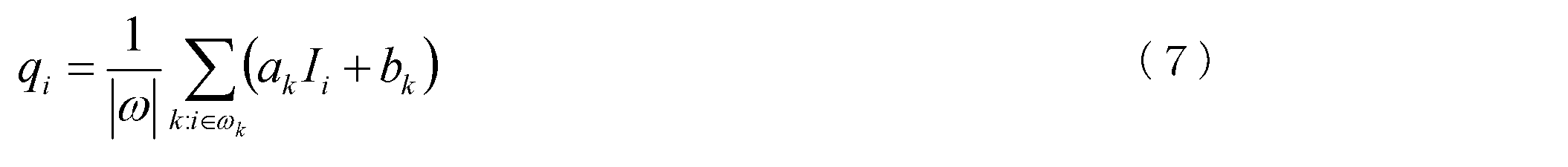
(7)式において、|ω|は注目画素および周囲画素の画素数、即ち5×5の配列において25である。(axp、bxp)は、ガイデッドフィルタにおいて周囲画素に対して算出された係数である。
注目画素に対するG色信号成分の補間により、G補間画像信号成分が生成される。以後、同様にCy色信号成分、Or色信号成分、B色信号成分、及びR色信号成分もG色信号成分と同様に補間が行われ、Cy補完画像信号成分、Or補間画像信号成分、B補間画像信号成分、及びR補間画像信号成分が生成される。このように全色信号成分の補間により補間画像信号が生成される。
以上のような構成の第3の実施形態の画像処理システムによっても、画素毎に微分値を算出し、微分値すなわち勾配情報に基づいて参照画像を作成し、参照画像に基づいて補間画像信号を作成可能である。それゆえ、マルチバンドの色信号成分によって構成される原画像信号から偽色の発生を抑えた補間画像信号を生成することが可能である。
次に、本発明の第4の実施形態に係る画像処理システムについて説明する。第4の実施形態はデモザイク処理及びMBデモザイク処理部の構成において第1の実施形態と異なっている。以下に、第1の実施形態と異なる点を中心に第4の実施形態について説明する。なお、第1の実施形態と同じ機能及び構成を有する部位には同じ符号を付す。
第4の実施形態では、MBデモザイク処理部以外のデジタルカメラの各部位の構成及び機能は第1の実施形態と同じである。
第4の実施形態で実行されるデモザイク処理について図11を用いて説明する。図11は、第4の実施形態のMBデモザイク処理部によって実行されるデモザイク処理を説明するための概念図である。
第4の実施形態では、適応的ジョイントバイラテラル補間法の代わりに、適応的カーネル関数を使用しないジョイントバイラテラル補間法(JBU参照)を用いて全色信号成分の補間を行う点において第1の実施形態と異なっている。
次に、このようなデモザイク処理を実行するMBデモザイク処理部の構成及び機能を、図12を用いて説明する。第2の実施形態におけるMBデモザイク処理部402は、分配部412、微分値算出部422、適応的カーネル算出部432、参照画像作成部442、及び補間画像作成部452によって構成される。
分配部412、微分値算出部422、適応的カーネル算出部432、および参照画像作成部452の機能は、第1の実施形態と同じである。したがって、第1の実施形態と同様に、適応的ガウシアン補間法により参照画像信号が生成される。
第1の実施形態と異なり、補完画像作成部452では、ジョイントバイラテラル補間法によりG色信号成分、Cy色信号成分、Or色信号成分、B色信号成分、及びR色信号成分の補間が行われる。ジョイントバイラテラル補間法では、(4)式において適応的カーネル関数の代わりに、注目画素から周囲画素までの距離に応じて小さくなる重み付けをk(xi-x)として、注目画素の色信号成分が算出される。
以上のような構成の第4の実施形態の画像処理システムによっても、画素毎に微分値を算出し、微分値すなわち勾配情報に基づいて参照画像を作成し、参照画像に基づいて補間画像信号を作成可能であるそれゆえ、マルチバンドの色信号成分によって構成される原画像信号から偽色の発生を抑えた補間画像信号を生成することが可能である。
なお、適応的カーネル関数を用いずにジョイントバイラテラル補間法により色信号成分を補間する構成であるため、第1の実施形態に比べて偽色の発生の抑止効果が低下する。しかし、参照画像そのものの作成に適応的カーネル関数を用いているので、前述のように参照画像の偽像の発生が低減化されている。それゆえ、従来公知の線形補間により補間画像を作成することに比べて、偽色の発生の抑止効果を向上させることが可能である。
次に、本発明の第5の実施形態に係る画像処理システムについて説明する。第5の実施形態はデモザイク処理及びMBデモザイク処理部の構成において第1の実施形態と異なっている。以下に、第1の実施形態と異なる点を中心に第5の実施形態について説明する。なお、第1の実施形態と同じ機能及び構成を有する部位には同じ符号を付す。
第5の実施形態では、MBデモザイク処理部以外のデジタルカメラの各部位の構成及び機能は第1の実施形態と同じである。
第5の実施形態で実行されるデモザイク処理について図13を用いて説明する。図13は、第5の実施形態のMBデモザイク処理部によって実行されるデモザイク処理の処理を説明するための概念図である。
第5の実施形態では、適応的カーネル関数を用いずに通常のガウシアン補間法によりG信号成分を補完して参照画像が作成される(GU参照)。
次に、このようなデモザイク処理を実行するMBデモザイク処理部の構成及び機能を、図14を用いて説明する。第5の実施形態におけるMBデモザイク処理部403は、分配部413、微分値算出部423、適応的カーネル算出部433、参照画像作成部443、及び補間画像作成部453によって構成される。
分配部413、微分値算出部423、および補間画像作成部453の構成は、第1の実施形態と同じである。適応的カーネル算出部433は、第1の実施形態と同様に、全画素に対する適応的カーネル関数を算出する。しかし、第1の実施形態と異なり、適応的カーネル関数は参照画像作成部443には送信されず、補間画像作成部453にのみ送信される。
参照画像作成部443では、第1の実施形態と異なり、G原画像信号成分に対してガウシアン補間法によりG色信号成分を補間し、参照画像信号を生成する。生成した参照画像信号は補間画像作成部453に送信される。
前述のように、補間画像作成部453の機能は第1の実施形態と同じであって、適応的カーネル関数、参照画像信号、および原画像信号の各色信号成分に基づいて、各色信号成分の補間を行う。各色信号成分の補間により、全色信号成分を有する画素信号が全画素に対して生成されるので、補間画像信号が生成される。
以上のような構成の第5の実施形態の画像処理システムによっても、画素毎に微分値を算出し、参照画像を作成し、参照画像と微分値即ち勾配情報とに基づいて補間画像を作成可能である。それゆえ、マルチバンドの色信号成分によって構成される原画像信号から偽色の発生を抑えた補間画像信号を生成することが可能である。
なお、適応的カーネル関数を用いずに通常のガウシアン補間法により参照画像を作成する構成であるため、第1の実施形態に比べて偽色発生の低減化効果は低下する。しかし、適応的カーネル関数を用いて補間画像を作成するため、従来公知の線形補間により補間画像を作成することに比べて、偽色の発生を低下させることが可能である。
次に、本発明の第6の実施形態に係る画像処理システムについて説明する。第6の実施形態はデモザイク処理及びMBデモザイク処理部の構成において第1の実施形態と異なっている。以下に、第1の実施形態と異なる点を中心に第6の実施形態について説明する。なお、第1の実施形態と同じ機能及び構成を有する部位には同じ符号を付す。
第6の実施形態では、MBデモザイク処理部以外のデジタルカメラの各部位の構成及び機能は第1の実施形態と同じである。
第6の実施形態で実行されるデモザイク処理について図15を用いて説明する。図15は、第6の実施形態のMBデモザイク処理部によって実行されるデモザイク処理の処理を説明するための概念図である。
第6の実施形態では、適応的カーネル関数を用いずに通常のガウシアン補間法によりG信号成分を補間して参照画像が作成される(GU参照)。また、適応的ジョイントバイラテラル補間法に用いる適応的カーネル関数が第1の実施形態と異なっている。第6の実施形態では、第2の実施形態と同様に、参照画像を用いて算出した適応的カーネル関数を用いている。
次に、このようなデモザイク処理を実行するMBデモザイク処理部の構成及び機能を、図16を用いて説明する。第6の実施形態におけるMBデモザイク処理部404は、分配部414、微分値算出部424、適応的カーネル算出部434、参照画像作成部444、及び補間画像作成部454によって構成される。
第6の実施形態では、分配部414、微分値算出部424、適応的カーネル算出部434、参照画像作成部444、及び補間画像作成部454の機能の一部が第1の実施形態と異なる。
第1の実施形態と異なり、分配部414から微分値算出部424には色信号成分が送信されず、参照画像作成部444及び補間画像作成部454に色信号成分が送信される。
参照画像作成部444では、第5の実施形態のように、適応的カーネル関数を用いずにG原画像信号成分に対して通常のガウシアン補間法によりG色信号成分を補間し、参照画像信号を生成する。生成した参照画像信号は、第2の実施形態と同様に、微分値算出部424及び補間画像作成部454に送信される。
第2の実施形態と同様に、微分値算出部424では、参照画像信号を構成するG色信号成分を用いて画素毎の2方向の微分値を算出する。算出された微分値が適応的カーネル算出部434に送信される。適応的カーネル算出部434では、参照画像信号に基づいて算出された微分値を用いて適応的カーネル関数を算出する。算出された適応的カーネル関数が補間画像作成部454に送信される。
補間画像作成部454では、通常のガウシアン補間法により生成した参照画像信号及び参照画像信号による適応的カーネル関数を用いて各色信号成分の補間を行う。
以上のような構成の第6の実施形態の画像処理システムによっても、参照画像を作成し、参照画像に基づく微分値を算出し、参照画像と微分値即ち勾配情報とに基づいて補間画像信号を作成可能である。それゆえ、マルチバンドの色信号成分によって構成される原画像信号から偽色の発生を抑えた補間画像信号を生成することが可能である。
なお、第5の実施形態と同様に、適応的カーネル関数を用いずにガウシアン補間法により参照画像を作成する構成であるため、第1の実施形態に比べて偽色発生の低減化効果は低下する。しかし、適応的カーネル関数を用いて補間画像を作成するため、従来公知の線形補間により補間画像を作成することに比べて、偽色の発生を低下させることが可能である。
本発明を諸図面や実施例に基づき説明してきたが、当業者であれば本開示に基づき種々の変形や修正を行うことが容易であることに注意されたい。従って、これらの変形や修正は本発明の範囲に含まれることに留意されたい。
例えば、上記の第1~第6の実施形態において、全色信号成分そのものが補間画像作成部45、450、451、452、453、454において補間される構成であるが、一部の色信号成分においては色差を用いて補間を行うことにより色信号成分を生成してもよい。
例えば、第1の実施形態において色差を利用した補間画像信号の生成について説明する。図17に示すように、G補間画像信号成分gIIS、Cy補間画像信号成分cyIIS、及びOr補間画像信号成分orIISは、第1の実施形態と同様に生成される。
生成されたCy補間画像信号成分cyIISの中から、B原画像信号成分bOISが存在する画素と同じ画素におけるCy色信号成分が抽出される。減算器46により、B原画像信号成分bOISから、抽出されたCy色信号成分が減算され、第1の色差原画像信号成分d1OISが生成される。同様に、Or補間画像信号成分orIIS及びR原画像信号成分rOISから第2の色差原画像信号成分d2OISが生成される。
適応的カーネル関数、参照画像信号RIS、及び第1の色差原画像信号成分d1OISを用いて、適応的ジョイントバイラテラル補間法により、生成されていない第1の色差信号成分が全画素に対して補間される。第1の色差信号成分の補間により第1の色差補間画像信号成分d1IISが生成される。同様に、適用的カーネル関数、参照画像信号RIS、及び第2の色差原画像信号成分d2OISを用いて適応的ジョイントバイラテラル補間法により、第2の色差補間画像信号成分d2IISが生成される。
加算器47により、第1の色差補間画像信号成分d1IISに、Cy補間画像信号成分cyIISが加算されることにより、B補間画像信号成分bIISが生成される。同様に、第2の色差補間画像信号成分d2IISに、Or補間画像信号成分orIISが加算されることにより、R補間画像信号成分rIISが生成される。
このように、色差を用いて補間を行うことも可能である。色差を用いて補間を行うことにより、いずれかの色信号成分のノイズ成分が多い場合であっても、当該画素における極端な色再現性の悪化を抑止することが可能である。
なお、上述の説明においては、第1の実施形態の変形例において色差を利用した補間が行われているが、第2~第6の実施形態においても、同様に色差を利用した補間を行うことは可能である。
また、上述の説明においては、Cy色信号成分及びB色信号成分の色差と、Or色信号成分及びR色信号成分の色差とが算出され、補間が行われている。色差の算出に用いる色差の互いのバンドが近くなるほど、色再現性を向上に有利である。ただし、色差の算出はこれらの組合わせに限定されない。例えば、G補間画像信号成分とCy原画像信号成分とに基づく色差信号成分を補間する構成であってもよい。
また、第1~第6の実施形態において、G原画像信号成分を用いて参照画像信号を生成する構成であるが、補間画像信号のいずれかの色信号成分を生成した後に、生成した補間画像信号を参照画像信号として他の色信号成分の補間に用いても良い。
上記の第1~第6の実施形態において、G原画像信号成分に基づいて生成された参照画像信号を用いて全色信号成分そのものが補間される構成であるが、例えば、生成したG補間画像信号成分を参照画像信号(二次参照画像)として、Cy原画像信号成分、OR原画像信号成分、B原画像信号成分、及びR原画像信号成分の補間に用いてもよい。
G原画像信号成分に基づいて生成される参照画像信号よりも、補間画像信号成分の方が一般的に、色信号成分の再現性は高い。それゆえ、補間画像信号成分を参照画像信号として用いることにより、補間画像の再現性を向上させることが可能である。
また、第1~第6の実施形態において、CFA21aではGカラーフィルタの割合が最大であるが、他のバンドのカラーフィルタの割合が最大であってもよい。
また、第1、第2、第4~第6の実施形態において、(適用的)ジョイントバイラテラル補間では、注目画素と周囲画素との画素値の差分に応じた重み付けr(Ixi-Ix)を用いる構成であるが、注目画素と周囲画素との類似性に応じた他の重み付けを用いてもよい。
(適用的)ジョイントバイラテラル補間法では、参照画像において注目画素と周囲画素との光学情報が似ている、即ち画素値の差が近い場合に、周囲画素の重み付けが大きくなるように構成される。したがって、このような重み付けの代わりに、上述のように類似性が大きいほど、大きな重み付けをすることにより上述の実施形態と同様の効果を得ることが可能である。
例えば、参照画像信号において、注目画素を中心とする3行3列の画素と、周囲画素を中心とする3行3列の画素の画素値の差の相乗平均を、注目画素と周囲画素との類似性として、相乗平均に応じて重み付けを行ってもよい。
また、第1~第4の実施形態において、最多のGカラーフィルタの割合は50%であるが、50%に限定されない。参照画像信号の生成には適用的ガウシアン補間法が適用されるので、通常のガウシアン補間法に比べて色成分の精度が高い参照画像信号を生成可能である。
また、第5、第6の実施形態において、CFA21aの各画素に対して斜方に隣接する2画素に対応するカラーフィルタのバンドが等しい構成であるが、このような配置でなくてもよい。第5、第6の実施形態では、参照画像信号の生成に適用的カーネル関数を用いないので、上述のようなカラーフィルタ配置に限定されない。
また、第1~第6の実施形態において、CFA21aには5バンドのカラーフィルタが設けられる構成であるが、3バンド以上であればよい。
また、第2の実施形態において、単一の微分値算出部420によって、原画像信号に基づく微分値及び参照画像信号に基づく微分値が算出される構成であるが、別々の微分値算出部によって別々に算出されてもよい。
また、第6の実施形態において、参照画像信号に基づいて注目画素の斜め方向に沿った微分値が算出される構成であるが、行方向及び列方向に沿った微分値を算出する構成であってもよい。参照画像信号には、欠落した画素信号が無いので行方向及び列方向に沿った微分値が算出可能である。また、上述のように第2の実施形態において、別々の微分値算出部を用いて参照画像信号に基づく微分値を算出する場合には、参照画像信号に基づく微分値の算出において行方向及び列方向に沿った微分値を算出する構成であってもよい。
また、第1、第2の実施形態において、適応的カーネル関数の算出に用いる所定の設計パラメータhには、適応的ガウシアン補間法及び適応的ジョイントバイラテラルアップサンプリングの両者ともに同一の値が用いられる構成であるが、両者の間で異なる値が用いられる構成であってもよい。
また、第1~第6の実施形態において、各色に対応する原画像信号成分において欠落した画素信号を補間することにより参照画像信号及び各色に対応する補間画像信号成分が生成される構成であるが、原画像信号成分において欠落せずに検出された画素も注目画素として補間を行ってもよい。
また、第1~第6の実施形態において、画像処理システムはデジタルカメラ10に適用される構成であるが、一部の色信号成分が欠落するマルチバンドの画像信号を処理するいかなる機器に適用することが出来る。例えば、ビデオカメラ及び電子内視鏡に適用することも可能であり、さらには、記録メディアや接続ケーブルを介して受信する画像信号の処理を行う画像処理装置に適用することも可能である。
10 デジタルカメラ
20 撮像素子
21a カラーフィルタアレイ(CFA)
21u カラーフィルタ繰返し単位
30 画像信号処理部
40、400、401、402、403、404 マルチバンドデモザイク(MB)処理部
41、410、411、412、413、414 分配部
42、420、421、422、423、424 微分値算出部
43、430、431、432、433、434 適応的カーネル算出部
44、440、441、442、443、444 参照画像作成部
45、450、451、452、453、454 補間画像作成部
46 減算器
47 加算器
IIS 補間画像信号
bIIS B補間画像信号成分
cyIIS Cy補間画像信号成分
d1OIS、d2OIS 第1、第2の色差原画像信号成分
gIIS G補間画像信号成分
orIIS Or補間画像信号成分
rIIS R補間画像信号成分
RIS 参照画像信号
OIS 原画像信号
bOIS B原画像信号成分
cyOIS Cy原画像信号成分
gOIS G原画像信号成分
orOIS Or原画像信号成分
rOIS R原画像信号成分
RIS 参照画像信号
Claims (14)
- 第1~第m(mは3以上の整数)の色信号成分のいずれかを有する複数の画素信号によって構成される原画像信号から、前記原画像信号を構成する全画素信号が第1~第mの色信号成分を有するように前記色信号成分の補間を行う画像処理システムであって、
前記原画像信号を受信する受信部と、
前記画素信号それぞれに対応する画素を挟む同色の2画素を用いて前記画素信号の微分値を算出する微分値算出部と、
前記原画像信号の中の前記第1の色信号成分を用いて一次参照画像を作成する参照画像作成部と、
前記一次参照画像を用いて、全色信号成分を補間して補間画像を作成する補間画像作成部とを備え、
前記一次参照画像及び前記補間画像の少なくとも一方は、微分値を用いて作成される
ことを特徴とする画像処理システム。 - 請求項1に記載の画像処理システムであって、前記原画像信号を構成する複数の前記画素信号の中で前記第1の色信号成分の要素数が最大であり、前記補間画像のみが前記微分値を用いて作成され、前記参照画像作成部は前記第1の色信号成分を補間することにより前記第1の色信号成分のみを有する前記全画素信号によって構成される一次参照画像信号を作成することを特徴とする画像処理システム。
- 請求項1に記載の画像処理システムであって、
前記微分値算出部は、前記原画像信号を用いて前記画素毎に第1の前記微分値を算出し、
前記参照画像作成部は、前記第1の微分値を用いて前記第1の色信号成分を補間することにより、前記第1の色信号成分のみを有する前記全画素信号によって構成される一次参照画像信号を作成する
ことを特徴とする画像処理システム。 - 請求項3に記載の画像処理システムであって、前記参照画像作成部は、適応的ガウシアン補間法により、前記第1の微分値を用いて前記第1の色信号成分を補間することを特徴とする画像処理システム。
- 請求項3または請求項4に記載の画像処理システムであって、前記一次参照画像のみが前記第1の微分値を用いて作成されることを特徴とする画像処理システム。
- 請求項5に記載の画像処理システムであって、前記補間画像作成部はガイデッドフィルタにより、前記全色信号成分を補間することを特徴とする画像処理システム。
- 請求項5に記載の画像処理システムであって、前記補間画像作成部はジョイントバイラテラル補間により、前記全色信号成分を補間することを特徴とする画像処理システム。
- 請求項1、請求項2、及び請求項4のいずれかに記載の画像処理システムであって、
前記微分値算出部は、前記原画像信号を用いて前記画素毎に第2の前記微分値を算出し、
前記補間画像作成部は、前記一次参照画像と前記第2の微分値を用いて前記補間画像を作成する
ことを特徴とする画像処理システム。 - 請求項3に記載の画像処理システムであって、前記補間画像作成部は前記一次参照画像と前記第1の微分値を用いて前記補間画像を作成することを特徴とする画像処理システム。
- 請求項1~請求項4のいずれかに記載の画像処理システムであって、
前記微分値算出部は、前記一次参照画像を用いて前記画素毎に第3の前記微分値を算出し、
前記補間画像作成部は、前記一次参照画像と前記第3の微分値を用いて前記補間画像を作成する
ことを特徴とする画像処理システム。 - 請求項8または請求項10に記載の画像処理システムであって、前記補間画像作成部は、適応的ジョイントバイラテラル補間によって、前記全色信号成分を補間することを特徴とする画像処理システム。
- 請求項11に記載の画像処理システムであって、前記適応的ジョイントバイラテラル補間では、前記画素間の画素信号の信号強度の差に基づく重付け、或いは算出に用いる複数の前記画素の周囲の類似性に基づく重付けが用いられることを特徴とする画像処理システム。
- 請求項1~請求項12のいずれかに記載の画像処理システムであって、
前記補間画像作成部は、
前記一次参照画像を用いて前記第2の色信号成分の補間を行い、
前記第3の色信号成分を有する前記画素信号に対応する前記第2の色信号成分と、前記第3の色信号成分との色差を算出し、
前記一次参照画像を用いて前記色差を補間し、
補完された前記色差と補間された前記第2の色信号成分とに基づいて、前記全画素信号に対応する前記第3の色信号成分が作成する
ことを特徴とする画像処理システム。 - 請求項1~請求項12のいずれかに記載の画像処理システムであって、
前記補間画像作成部は、
前記一次参照画像を用いて前記第1~第mの色信号成分のいずれかの補間を行い、
補間された前記色信号成分によって構成される画像を二次参照画像とし、前記二次参照画像を用いて、補間の行われていない前記色信号成分の補間を行う
ことを特徴とする画像処理システム。
Priority Applications (1)
| Application Number | Priority Date | Filing Date | Title |
|---|---|---|---|
| US14/117,018 US20140072214A1 (en) | 2011-05-11 | 2012-04-27 | Image processing system |
Applications Claiming Priority (2)
| Application Number | Priority Date | Filing Date | Title |
|---|---|---|---|
| JP2011-106717 | 2011-05-11 | ||
| JP2011106717A JP5709131B2 (ja) | 2011-05-11 | 2011-05-11 | 画像処理システム |
Publications (1)
| Publication Number | Publication Date |
|---|---|
| WO2012153489A1 true WO2012153489A1 (ja) | 2012-11-15 |
Family
ID=47138978
Family Applications (1)
| Application Number | Title | Priority Date | Filing Date |
|---|---|---|---|
| PCT/JP2012/002909 WO2012153489A1 (ja) | 2011-05-11 | 2012-04-27 | 画像処理システム |
Country Status (3)
| Country | Link |
|---|---|
| US (1) | US20140072214A1 (ja) |
| JP (1) | JP5709131B2 (ja) |
| WO (1) | WO2012153489A1 (ja) |
Families Citing this family (8)
| Publication number | Priority date | Publication date | Assignee | Title |
|---|---|---|---|---|
| JP2014178742A (ja) * | 2013-03-13 | 2014-09-25 | Samsung R&D Institute Japan Co Ltd | 画像処理装置、画像処理方法及び画像処理プログラム |
| JP5771677B2 (ja) | 2013-12-24 | 2015-09-02 | オリンパス株式会社 | 画像処理装置、撮像装置、プログラム及び画像処理方法 |
| JP6249234B2 (ja) * | 2014-10-23 | 2017-12-20 | 京セラドキュメントソリューションズ株式会社 | 画像処理装置 |
| CN106852190B (zh) * | 2014-10-23 | 2019-03-19 | 国立大学法人东京工业大学 | 图像处理单元、拍摄装置及图像处理方法 |
| WO2016084257A1 (ja) * | 2014-11-28 | 2016-06-02 | オリンパス株式会社 | 内視鏡装置 |
| ES2799524T3 (es) | 2015-06-24 | 2020-12-18 | Dow Global Technologies Llc | Procedimientos para preparar polímeros a base de etileno con resistencia en estado fundido mejorada |
| KR101700928B1 (ko) * | 2015-11-06 | 2017-02-01 | 인천대학교 산학협력단 | 다중 방향성 가중 보간 및 유도필터에 기초한 베이어 패턴 영상의 디모자이킹 방법 및 장치 |
| EP4124031A4 (en) * | 2020-03-16 | 2023-11-22 | Sony Semiconductor Solutions Corporation | IMAGING ELEMENT AND ELECTRONIC INSTRUMENT |
Citations (3)
| Publication number | Priority date | Publication date | Assignee | Title |
|---|---|---|---|---|
| JP2000184386A (ja) * | 1998-01-08 | 2000-06-30 | Fuji Photo Film Co Ltd | 固体撮像装置および信号処理方法 |
| JP2007306447A (ja) * | 2006-05-15 | 2007-11-22 | Sony Corp | 撮像装置、および画像処理方法、並びにコンピュータ・プログラム |
| JP2009105977A (ja) * | 2009-02-09 | 2009-05-14 | Canon Inc | 信号処理装置及び方法 |
Family Cites Families (4)
| Publication number | Priority date | Publication date | Assignee | Title |
|---|---|---|---|---|
| US7088392B2 (en) * | 2001-08-27 | 2006-08-08 | Ramakrishna Kakarala | Digital image system and method for implementing an adaptive demosaicing method |
| US7889949B2 (en) * | 2007-04-30 | 2011-02-15 | Microsoft Corporation | Joint bilateral upsampling |
| KR101389562B1 (ko) * | 2007-11-15 | 2014-04-25 | 삼성전자주식회사 | 이미지 처리 장치 및 방법 |
| KR101027323B1 (ko) * | 2010-01-20 | 2011-04-06 | 고려대학교 산학협력단 | 비대칭 가우시안 필터를 이용한 영상 보간 장치 및 방법 |
-
2011
- 2011-05-11 JP JP2011106717A patent/JP5709131B2/ja not_active Expired - Fee Related
-
2012
- 2012-04-27 US US14/117,018 patent/US20140072214A1/en not_active Abandoned
- 2012-04-27 WO PCT/JP2012/002909 patent/WO2012153489A1/ja active Application Filing
Patent Citations (3)
| Publication number | Priority date | Publication date | Assignee | Title |
|---|---|---|---|---|
| JP2000184386A (ja) * | 1998-01-08 | 2000-06-30 | Fuji Photo Film Co Ltd | 固体撮像装置および信号処理方法 |
| JP2007306447A (ja) * | 2006-05-15 | 2007-11-22 | Sony Corp | 撮像装置、および画像処理方法、並びにコンピュータ・プログラム |
| JP2009105977A (ja) * | 2009-02-09 | 2009-05-14 | Canon Inc | 信号処理装置及び方法 |
Also Published As
| Publication number | Publication date |
|---|---|
| US20140072214A1 (en) | 2014-03-13 |
| JP2012239038A (ja) | 2012-12-06 |
| JP5709131B2 (ja) | 2015-04-30 |
Similar Documents
| Publication | Publication Date | Title |
|---|---|---|
| JP5709131B2 (ja) | 画像処理システム | |
| JP5451782B2 (ja) | 画像処理装置および画像処理方法 | |
| EP2312858B1 (en) | Image processing apparatus, imaging apparatus, image processing method, and program | |
| US9509978B2 (en) | Image processing method, image processing apparatus, image-capturing apparatus, and image processing program | |
| JP5519083B2 (ja) | 画像処理装置、方法、プログラムおよび撮像装置 | |
| US9338364B2 (en) | Imaging device and image generation method | |
| TWI737979B (zh) | 圖像去馬賽克裝置及方法 | |
| US8086032B2 (en) | Image processing device, image processing method, and image pickup apparatus | |
| JP2012239103A (ja) | 画像処理装置、および画像処理方法、並びにプログラム | |
| WO2016047240A1 (ja) | 画像処理装置、撮像素子、撮像装置および画像処理方法 | |
| JP5943393B2 (ja) | 撮像装置 | |
| WO2017169039A1 (ja) | 画像処理装置、撮像装置、および画像処理方法、並びにプログラム | |
| JP5718138B2 (ja) | 画像信号処理装置及びプログラム | |
| US8441543B2 (en) | Image processing apparatus, image processing method, and computer program | |
| JP5268321B2 (ja) | 画像処理装置及び画像処理方法、画像処理プログラム | |
| US8223231B2 (en) | Imaging apparatus and image processing program | |
| JP5036524B2 (ja) | 画像処理装置、画像処理方法、プログラムおよび撮像装置 | |
| JP7183015B2 (ja) | 画像処理装置、画像処理方法、及びプログラム | |
| JP5761979B2 (ja) | ノイズ除去システムおよび撮像装置 | |
| WO2015083502A1 (ja) | 画像処理装置、該方法および該プログラム | |
| JP5912586B2 (ja) | 画像信号処理方法及び画像信号処理回路、並びに撮像装置 | |
| JP2011151597A (ja) | 画像処理装置および画像処理プログラム並びに電子カメラ | |
| WO2015083499A1 (ja) | 画像処理装置、該方法および該プログラム | |
| JP5454820B2 (ja) | 画像処理装置及び画像処理方法、画像処理プログラム | |
| JP4334484B2 (ja) | 画素信号処理装置及び方法 |
Legal Events
| Date | Code | Title | Description |
|---|---|---|---|
| 121 | Ep: the epo has been informed by wipo that ep was designated in this application |
Ref document number: 12781930 Country of ref document: EP Kind code of ref document: A1 |
|
| NENP | Non-entry into the national phase |
Ref country code: DE |
|
| WWE | Wipo information: entry into national phase |
Ref document number: 14117018 Country of ref document: US |
|
| 122 | Ep: pct application non-entry in european phase |
Ref document number: 12781930 Country of ref document: EP Kind code of ref document: A1 |