US9504541B2 - Method and system for designing custom restorations for dental implants - Google Patents
Method and system for designing custom restorations for dental implants Download PDFInfo
- Publication number
- US9504541B2 US9504541B2 US11/325,990 US32599006A US9504541B2 US 9504541 B2 US9504541 B2 US 9504541B2 US 32599006 A US32599006 A US 32599006A US 9504541 B2 US9504541 B2 US 9504541B2
- Authority
- US
- United States
- Prior art keywords
- design
- dental restoration
- values
- value
- component
- Prior art date
- Legal status (The legal status is an assumption and is not a legal conclusion. Google has not performed a legal analysis and makes no representation as to the accuracy of the status listed.)
- Active, expires
Links
Images


Classifications
-
- G—PHYSICS
- G05—CONTROLLING; REGULATING
- G05B—CONTROL OR REGULATING SYSTEMS IN GENERAL; FUNCTIONAL ELEMENTS OF SUCH SYSTEMS; MONITORING OR TESTING ARRANGEMENTS FOR SUCH SYSTEMS OR ELEMENTS
- G05B19/00—Program-control systems
- G05B19/02—Program-control systems electric
- G05B19/18—Numerical control [NC], i.e. automatically operating machines, in particular machine tools, e.g. in a manufacturing environment, so as to execute positioning, movement or co-ordinated operations by means of program data in numerical form
- G05B19/4097—Numerical control [NC], i.e. automatically operating machines, in particular machine tools, e.g. in a manufacturing environment, so as to execute positioning, movement or co-ordinated operations by means of program data in numerical form characterised by using design data to control NC machines, e.g. CAD/CAM
-
- A—HUMAN NECESSITIES
- A61—MEDICAL OR VETERINARY SCIENCE; HYGIENE
- A61C—DENTISTRY; APPARATUS OR METHODS FOR ORAL OR DENTAL HYGIENE
- A61C13/00—Dental prostheses; Making same
- A61C13/0003—Making bridge-work, inlays, implants or the like
- A61C13/0004—Computer-assisted sizing or machining of dental prostheses
-
- A—HUMAN NECESSITIES
- A61—MEDICAL OR VETERINARY SCIENCE; HYGIENE
- A61C—DENTISTRY; APPARATUS OR METHODS FOR ORAL OR DENTAL HYGIENE
- A61C13/00—Dental prostheses; Making same
- A61C13/08—Artificial teeth; Making same
- A61C13/09—Composite teeth, e.g. front and back section; Multilayer teeth
-
- A61C5/10—
-
- A—HUMAN NECESSITIES
- A61—MEDICAL OR VETERINARY SCIENCE; HYGIENE
- A61C—DENTISTRY; APPARATUS OR METHODS FOR ORAL OR DENTAL HYGIENE
- A61C5/00—Filling or capping teeth
- A61C5/70—Tooth crowns; Making thereof
- A61C5/77—Methods or devices for making crowns
-
- G—PHYSICS
- G05—CONTROLLING; REGULATING
- G05B—CONTROL OR REGULATING SYSTEMS IN GENERAL; FUNCTIONAL ELEMENTS OF SUCH SYSTEMS; MONITORING OR TESTING ARRANGEMENTS FOR SUCH SYSTEMS OR ELEMENTS
- G05B2219/00—Program-control systems
- G05B2219/30—Nc systems
- G05B2219/35—Nc in input of data, input till input file format
- G05B2219/35134—3-D cad-cam
-
- G—PHYSICS
- G05—CONTROLLING; REGULATING
- G05B—CONTROL OR REGULATING SYSTEMS IN GENERAL; FUNCTIONAL ELEMENTS OF SUCH SYSTEMS; MONITORING OR TESTING ARRANGEMENTS FOR SUCH SYSTEMS OR ELEMENTS
- G05B2219/00—Program-control systems
- G05B2219/30—Nc systems
- G05B2219/45—Nc applications
- G05B2219/45167—Dentist, dental manufacture
-
- Y—GENERAL TAGGING OF NEW TECHNOLOGICAL DEVELOPMENTS; GENERAL TAGGING OF CROSS-SECTIONAL TECHNOLOGIES SPANNING OVER SEVERAL SECTIONS OF THE IPC; TECHNICAL SUBJECTS COVERED BY FORMER USPC CROSS-REFERENCE ART COLLECTIONS [XRACs] AND DIGESTS
- Y02—TECHNOLOGIES OR APPLICATIONS FOR MITIGATION OR ADAPTATION AGAINST CLIMATE CHANGE
- Y02P—CLIMATE CHANGE MITIGATION TECHNOLOGIES IN THE PRODUCTION OR PROCESSING OF GOODS
- Y02P90/00—Enabling technologies with a potential contribution to greenhouse gas [GHG] emissions mitigation
- Y02P90/02—Total factory control, e.g. smart factories, flexible manufacturing systems [FMS] or integrated manufacturing systems [IMS]
Definitions
- This invention relates to the field of dental restorations, particularly implant dentistry.
- it relates to interrelating the design of custom abutments and the planning of restorations such as crowns and bridges, to the design of combined abutment-crowns, and to the planning of implant placement.
- a dental restorative system that replaces a single tooth typically includes three components: the dental implant fixture, the abutment, and a crown. When more than on tooth is being replaced, a bridge may be used instead of a crown for each replaced tooth.
- the dental implant fixture anchors the restorative system to the jawbone.
- the crown replicates the contour and appearance of the visible portion of the restorative system, to match that of the natural dentition.
- the abutment connects the crown to the dental implant fixture.
- the abutment also holds the crown in proper position and alignment relative to the implant fixture, and absorbs the stress of chewing.
- Standard methods for preparing dental restorative systems require considerable time, labor and expense.
- U.S. Pat. No. 6,231,342 explains a standard method involving between six and ten trips of patient to a dentist's office to complete installation of a restorative system. Using more advanced techniques and equipment such as those discussed in U.S. Pat. Nos.
- the number of visits to the dentist's office may be reduced, as well as the cost of the restoration.
- the quality of the restoration may be improved.
- the three-above identified patents teach the design of a custom abutment. In part, measurements are utilized of the position and orientation both of the implant fixture and of the edentulous space. These measurements, along with information about the type of tooth being replaced, allow an abutment and tooth profile to be defined. The abutment approximates the profile of the tooth in reduced size, except in the transition emergence profile region, to match the tooth (i.e., crown) shape with that of the implant.
- the abutment must be designed not only to match the tooth profile, but also to meet other constraints such as angular orientation relative to other abutments in the restoration, angular orientation relative to the implant, angle of the emergence profile of the abutment from the implant, the combined thickness of the abutment and crown material, covering of the retaining screw, and so forth. These constraints limit the acceptable abutment and crown designs. These limitations are even more acute in cases where multiple implants are involved and multiple implant replacements limit the range of acceptable restorations.
- some embodiments aid in the design of tooth replacement, including abutments, crowns and combined abutment-crowns, by incorporating the above-mentioned constraints into the measurement and design process.
- the shape, size and orientation of the desired restoration may be controlled by the constraints so that the designer is assisted in planning the restoration. Since both the abutment and crown (or bridge) constraints are incorporated into the measurement and design process, the resulting design should be manufacturable without further significant technician involvement.
- Such systems and methods support the creation of a plan for dental implant placement that includes the design of the abutment and crown.
- Limitations such as the location of bone with sufficient density to support the implant and the location of nerves and other anatomical features introduce additional constraints on the prosthesis design. All of these constraints are taken into account in the design process to realize a restoration consistent with the complete set of constraints.
- a computer-implemented method for specifying design parameters for at least first and second dental restoration components (e.g., implants, abutments, copings and crowns) that must be installed in a cooperating relationship.
- Such a method comprises: receiving a set of design dimensional constraints which must be satisfied for each of the first and second dental restoration components; receiving a set of design parameters for each of the first and second dental restoration components; and assigning values to the design parameters of the first and second dental components such that there are not conflicts between the design parameter values and the design constraints.
- a computer-implemented method for specifying design parameters for at least first and second dental restoration components that must be installed in a cooperating relationship.
- Such a method comprises: receiving a set of design dimensional constraints which must be satisfied for each of the first and second dental restoration components; receiving a set of design parameters for each of the first and second dental restoration components; for the first dental restoration component, assigning a value to each of said design parameters, consistent with the constraints for said component; for the second dental restoration component, determining whether there is a conflict between possible values for a design parameter and the dimensional constraints for the first component and, if there is a conflict, changing a value of at least one design parameter for the first component and re-determining whether there is a conflict, until no conflict exists or it is established that for all values of the design parameters for the first component there will be conflict; assigning a value to a first design parameter of the second dental restoration component, consistent with all constraints; and repeating the preceding two acts until values have been assigned to all design parameters of the first and second
- a computer-implemented method of designing a dental restoration component comprising: receiving a set of design dimensional constraints which must be satisfied for the dental restoration component; receiving a set of design parameters for the dental restoration component; receiving a definition for a penalty function which takes into account at least more than one of said design parameters and which signals a constraint being reached when the value of any of said parameters violates a constraint; and using the penalty function, assigning a value to each of said design parameters for the dental restoration component, consistent with the constraints for said component.
- the penalty function may be used to assist, along with other factors, assigning a value to at least one of said design parameters.
- the signaling of a constraint being reached may involve the penalty function transitioning to a predetermined value.
- a computer-implemented method of designing a dental restoration component comprising: receiving a set of design dimensional constraints which must be satisfied for the dental restoration component; receiving a set of design parameters for the dental restoration component; and using at least in part a penalty function, assigning a value to each of said design parameters for the dental restoration component, consistent with the constraints for said component, said penalty function taking into account at least more than one of said design parameters and which signals a constraint being reached when the value of any of said parameters violates a constraint.
- Assigning a value to each of said design parameters may comprise assigning said values consistent with the corresponding value of the penalty function being at or near an extreme value of the penalty function. The extreme value may be a minimum value.
- the method may also include recording said assigned parameter values in a data structure on a computer-readable medium.
- the method may include operating a computer-aided manufacturing system in accordance with said values in said data structure, to manufacture at least one of said first and second components.
- a computer-implemented method of designing an optimized dental restoration component comprising: receiving a set of design dimensional constraints which must be satisfied for the component; receiving a set of design parameters for the component; assigning a value to each of said design parameters, consistent with the constraints for said component; determining whether there is a conflict between possible values for a design parameter and the dimensional constraints for the component and, if there is a conflict, changing a value of at least one design parameter for the component and re-determining whether there is a conflict, until no conflict exists or it is established that for all values of the design parameters for the component there will be conflict; repeating the “assigning” operation until values have been assigned to all design parameters of the component and no constraint or parameter value conflicts exist; and executing a penalty function to calculate an acceptable set of design parameter values for the component.
- Such a method may further include recording said acceptable set of parameter values in a data structure on a computer-readable medium. It also may include operating a computer-aided manufacturing system in accordance
- a computer-implemented method for specifying a least one common design feature for at least first and second dental restoration components that must be installed in a cooperating relationship comprising: receiving a set of design dimensional constraints which must be satisfied for each of the first and second dental restoration components; receiving a set of design parameters for each of the first and second dental restoration components; and assigning values to the common design feature for said first and second dental components such that there is an absence of conflicts between the design parameters and the design constraints of said components.
- the first and second components may comprise an abutment and a crown, and the at least one common design feature may be a common margin for the abutment and crown.
- a method for designing at least first and second dental restoration components that must be installed in a cooperating relationship, said method comprising: defining a set of design dimensional constraints which must be satisfied for each of the first and second dental restoration components; defining a set of design parameters for each of the first and second dental restoration components; and assigning values to the first and second dental components such that there is an absence of conflicts between the design parameters and the design constraints.
- a method for specifying design parameters for at least first and second dental restoration components that must be installed in a cooperating relationship comprising, with a computer system: defining a set of design dimensional constraints which must be satisfied for each of the first and second dental restoration components; defining a set of design parameters for each of the first and second dental restoration components; for the first dental restoration component, assigning a value to each of said design parameters, consistent with the constraints for said component; for the second dental restoration component, determining whether there is a conflict between possible values for a design parameter and the dimensional constraints for the first component and, if there is a conflict, changing a value of at least one design parameter for the first component and re-determining whether there is a conflict, until no conflict exists or it is established that for all values of the design parameters for the first component there will be conflict; assigning a value to a first design parameter of the second dental restoration component, consistent with all constraints; and repeating the previous two operations until values have been assigned to all design parameters of the first and second components and
- a method is taught of designing a dental restoration component, comprising: defining a set of design dimensional constraints which must be satisfied for the dental restoration component; defining a set of design parameters for the dental restoration component; defining for a penalty function which takes into account at least more than one of said design parameters and which signals a constraint being reached when the value of any of said parameters violates a constraint; and using the penalty function, assigning a value to each of said design parameters for the dental restoration component, consistent with the constraints for said component.
- the penalty function may be used to assist, along with other factors, assigning a value to at least one of said design parameters.
- a method for of designing a dental restoration component comprising: defining a set of design dimensional constraints which must be satisfied for the dental restoration component; defining a set of design parameters for the dental restoration component; and using at least in part a penalty function, assigning a value to each of said design parameters for the dental restoration component, consistent with the constraints for said component, said penalty function taking into account at least more than one of said design parameters and which signals a constraint being reached when the value of any of said parameters violates a constraint.
- Assigning a value to each of said design parameters comprises assigning said values consistent with the corresponding value of the penalty function being at or near an extreme value of the penalty function.
- the extreme value may be, and usually is, a minimum value.
- the assigned parameter values may be recorded in a data structure on a computer-readable medium.
- the method may also include operating a computer-aided manufacturing system in accordance with the assigned values, including (but not limited to) values in said data structure, to manufacture said first and second components.
- a method of designing an optimized dental restoration component comprising: defining a set of design dimensional constraints which must be satisfied for the component; defining a set of design parameters for the component; assigning a value to each of said design parameters, consistent with the constraints for said component; determining whether there is a conflict between possible values for a design parameter and the dimensional constraints for the component and, if there is a conflict, changing a value of at least one design parameter for the component and re-determining whether there is a conflict, until no conflict exists or it is established that for all values of the design parameters for the component there will be conflict; repeating the determining operation until values have been assigned to all design parameters of the component and no constraint or parameter value conflicts exist; and using a penalty function to calculate an acceptable set of design parameter values for the component.
- Such a method may further include recording said calculated set of parameter values in a data structure on a computer-readable medium. It also may further include operating a computer-aided manufacturing system in accordance with said calculated set of values in
- a method for specifying a least one common design feature for at least first and second dental restoration components that must be installed in a cooperating relationship comprising: providing a set of design dimensional constraints which must be satisfied for each of the first and second dental restoration components; providing a set of design parameters the at least one common design feature for each of the first and second dental restoration components; and assigning values to the common design feature for said first and second dental components such that there is an absence of conflicts between the values of said design parameters and the design constraints of said components.
- the first and second components comprise an abutment and a crown, and the at least one common design feature may a common margin for the abutment and crown.
- an article comprising a computer-readable signal, recorded on a computer-readable medium, and comprising instructions which, when executed, cause a computer system to perform a method for specifying design parameters for at least first and second dental restoration components that must be installed in a cooperating relationship, said method comprising: receiving a set of design dimensional constraints which must be satisfied for each of the first and second dental restoration components; receiving a set of design parameters for each of the first and second dental restoration components; and assigning values to the first and second dental components such that there is an absence of conflicts between the design parameters and the design constraints.
- an article comprising a computer-readable signal, recorded on a computer-readable medium, and comprising instructions which, when executed, cause a computer system to perform a method of specifying design parameters for at least first and second dental restoration components that must be installed in a cooperating relationship, comprising: receiving a set of design dimensional constraints which must be satisfied for each of the first and second dental restoration components; receiving a set of design parameters for each of the first and second dental restoration components; for the first dental restoration component, assigning a value to each of said design parameters, consistent with the constraints for said component; for the second dental restoration component, determining whether there is a conflict between possible values for a design parameter and the dimensional constraints for the first component and, if there is a conflict, changing a value of at least one design parameter for the first component and re-determining whether there is a conflict, until no conflict exists or it is established that for all values of the design parameters for the first component there will be conflict; assigning a value to a first design parameter of the second dental
- an article comprising a computer-readable signal, recorded on a computer-readable medium, and comprising instructions which, when executed, cause a computer system to perform a method of designing a dental restoration component, comprising: receiving a set of design dimensional constraints which must be satisfied for the dental restoration component; receiving a set of design parameters for the dental restoration component; receiving a definition for a penalty function which takes into account at least more than one of said design parameters and which signals a constraint being reached when the value of any of said parameters violates a constraint; and using the penalty function, assigning a value to each of said design parameters for the dental restoration component, consistent with the constraints for said component.
- the instructions when executed may further cause the penalty function to be used to assist, along with other factors, assigning a value to at least one of said design parameters.
- an article comprising a computer-readable signal, recorded on a computer-readable medium, and comprising instructions which, when executed, cause a computer system to perform a method of designing a dental restoration component, comprising: receiving a set of design dimensional constraints which must be satisfied for the dental restoration component; receiving a set of design parameters of said parameters for the dental restoration component; and using at least in part a penalty function, assigning a value to each of said design parameters for the dental restoration component, consistent with the constraints for said component, said penalty function taking into account at least more than one of said design parameters and which signals a constraint being reached when the value of any of said parameters violates a constraint.
- Assigning a value to each of said design parameters may comprise assigning said values consistent with the corresponding value of the penalty function being at or near an extreme value of the penalty function.
- the extreme value may be a minimum value, for example.
- Assigning the value to each of said design parameters is not limited to using the penalty function to do so.
- Said instructions may further effect recording said assigned parameter values in a data structure on a computer-readable medium.
- the article may further include instructions which, when executed, operate a computer-aided manufacturing system in accordance with said values in said data structure, to manufacture said at least one of first and second components.
- an article comprises a computer-readable signal, recorded on a computer-readable medium, and comprising instructions which, when executed, cause a computer system to perform a method of designing an optimized dental restoration component, comprising: receiving a set of design dimensional constraints which must be satisfied for the component; receiving a set of design parameters for the component; assigning a value to each of said design parameters, consistent with the constraints for said component; determining whether there is a conflict between possible values for a design parameter and the dimensional constraints for the component and, if there is a conflict, changing a value of at least one design parameter for the component and re-determining whether there is a conflict, until no conflict exists or it is established that for all values of the design parameters for the component there will be conflict; repeating the previous operation until values have been assigned to all design parameters of the component and no constraint or parameter value conflicts exist; and executing a penalty function to calculate an acceptable set of design parameter values for the component.
- the article may further include instructions which, when executed, operate a computer-aided manufacturing system
- an article comprising a computer-readable signal, recorded on a computer-readable medium, and comprising instructions which, when executed, cause a computer system to perform a method of specifying a least one common design feature for at least first and second dental restoration components that must be installed in a cooperating relationship, said method comprising: receiving a set of design dimensional constraints which must be satisfied for each of the first and second dental restoration components; receiving a set of design parameters for each of the first and second dental restoration components; and assigning values to the common design feature for said first and second dental components such that there is an absence of conflicts between the design parameters and the design constraints of said components.
- the first and second components may comprise an abutment and a crown, and the at least one common design feature is a common margin for the abutment and crown.
- a dental restoration abutment and a corresponding, paired dental restoration crown are provided, which when assembled together share between them a common margin, made any other processes noted above and suitable for the purpose.
- a single dental restoration component made using any of the foregoing processes is intended as part of this invention.
- FIG. 1 is a high-level conceptual block diagram of a first example of an implant restoration design process as taught herein, wherein as a predicate, the required implant(s) has(have) already been fixed (i.e., placed) in the patient's jaw;
- FIG. 2 is a high-level conceptual block diagram of a second example of an implant restoration design process as taught herein, wherein the implant(s) has(have) not already been fixed (i.e., placed) in the patient's jaw and the design of implant placement is part of such restoration process;
- FIG. 3 is a diagrammatic illustration, from a single side view, of an implant and an abutment showing several design parameters
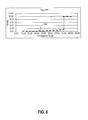
- FIG. 4 is a graph of three exemplary shoulder width penalty functions, non-normalized
- FIG. 5 is a graph of the same three exemplary shoulder width penalty functions, centered and normalized
- FIG. 6 is a graph of an example of an emergence angle penalty function
- FIG. 7 is a graph of an example of a shoulder width penalty function used in conjunction with the graph of FIG. 6 to demonstrate penalty function-constraint interaction;
- FIG. 8 is a graph of an example of a space-from-core penalty function discussed in relation to the penalty functions of FIGS. 6 and 7 ;
- FIG. 9 is a part-flow, part-block diagram useful for understanding the overall restoration planning process in which aspects of the present invention may be utilized.
- FIG. 10 (parts A and B) is a block diagram of a typical computer system that might be used to practice aspects of the invention that are computer-implemented, though the invention is not limited to any particular computer system.
- step is not intended to invoke the construction specified in 35 U.S.C. ⁇ 112, sixth paragraph unless a “step for” performing a function is recited in a claim.
- Abutment height is the distance from the implant-abutment interface to the top of the abutment
- Angulation or “inclination” refers to the tilt of the long axis of a tooth in a mesial/distal or facial/lingual direction.
- the “base” or “emergence profile region” is a zone from the implant interface to the margin, which interfaces with the soft tissue around a tooth or implant.
- the “core” is the central portion of an abutment above the margin or gum line.
- the “core region” is the zone from the margin to the top of the abutment, which interfaces with the restoration (i.e., crown or bridge).
- Core angle is the direction of the abutment core.
- Core height is the abutment height less average margin height.
- the “counterbore” is a hole in the occlusal portion of abutment that provides access for the retaining screw.
- the “crown” is the portion of a tooth or tooth restoration above the margin and, in the case of a restoration, is the final restorative component, typically fabricated in ceramic, metal or a combination of metal and ceramic.
- “Distance to crown model” is defined at multiple locations at the height of the contact points. It defines the space available for the coping and porcelain of the crown and is determined by subtracting the core width from the width of the crown model.
- Edentulous means without teeth.
- Edentulous space is a space where teeth are missing.
- the “emergence profile” of a restoration is the shape of the abutment as it transitions from the implant to the margin—normally located within the soft tissue.
- “Emergence profile angle” is determined by margin widths and heights and is a single angle (at any margin section) not including the transitions from the implant interface and to the margin. The maximum angle of the emergence profile must be within a case specific limit. The emergence profile angle should point to the contact points as defined by the crown model. Emergence profile angles may be approximated by taking the arctangent of the ratio of adjusted margin height to adjusted margin width. The target emergence profile angles are equal to the angles of the crown model at the margin heights in each of the specified directions. Limit emergence profile angles may be set by the cone angle limits that depend on the case specific clinician preferences and will be provide as a scalar.
- a “fixture” is a synonym for a dental implant.
- a fixture, or implant is mounted in the maxillary or mandibular bone structure, and used as a base to mount a dental abutment.
- the “margin” is the locus of the outer edge of the joint between abutment and crown.
- Margin widths are measured in multiple locations about a restoration, in the base region, from the center of the abutment core to the margin. Margin widths interact with the counterbore (and implant axis) since the counterbore must be contained within the margins and should be contained within the core.
- a “model” is a representation of an actual component, e.g. an abutment model or crown model.
- Opclusal clearance is the distance to the opposing tooth (or teeth). It is defined differently for anterior and posterior teeth, and defines the space available for the coping and porcelain of the crown.
- the “papilla” is the rise in soft tissue in the interproximal (i.e., between adjacent teeth) region.
- the “Path of Insertion” is an imaginary direction along which the restoration will be placed onto or removed from the abutment (or prepared tooth) . . .
- the abutment must permit the restoration to be placed along the POI.
- a “pontic” is a tooth (or teeth) in a bridge that is(are) not supported by an abutment (implant abutment or prepared tooth).
- a “restoration” is a structure creating a complete prosthetic tooth (e.g., implant, abutment, and crown)
- the “shoulder” of a restoration is the area between the abutment margin edge, at the end of the emergence profile, and the core. Shoulder widths are measured in multiple locations and are the distance from the margin to the core. Shoulder widths define the restoration thicknesses at the margin. Facial widths are most critical, the interproximal widths are next in importance and the lingual widths are the least important. Shoulder widths interact with margin widths to affect core widths.
- the “soft tissue,” in the mouth, refers to the gingival, or gum, tissue
- a “soft tissue model” is a flexible model of the gingival (gum) tissue that is separate from a study cast
- Subjectgingival depth is the distance of the margin height below the soft tissue (gum).
- Taper refers to the reduction of the core above the margin of the abutment to allow placement of the restoration. Taper angle is the reduction in core width as a function of core height, measured from the core axis. The amount of taper affects retention—the smaller the taper angle, the greater the retention.
- U.S. Pat. Nos. 5,674,069, 5,989,029 and 6,231,342 teach computer-aided approaches to the design and fabrication of abutments for dental restorations.
- the process of designing and implementing a dental restoration for an implant fixture requires that the crown (or bridge, etc.) be geometrically compatible with the supporting abutment.
- dental technicians exercise their acquired judgment to create acceptable abutment and crown designs. That is, even when custom abutment and crown are produced by a computer-aided design and manufacturing (CAD/CAM) process, a dental technician still has to use craftsmanship.
- CAD/CAM computer-aided design and manufacturing
- crowns designed this way may require abutment geometry that is not consistent with limitations such as the angulation limit between the abutment and implant, abutment angle between the implant the margin, crown thickness, retaining screw counterbore location or manufacturing considerations.
- a process 100 is outlined schematically for use in the circumstance that implant placement has already been determined.
- act 110 the positions and angles of the implants are measured and input to a computer-maintained database (not shown).
- act 120 appropriate measurements are made of the soft tissue in the implant's space. These measurements may include, for example, the location of the surface of the soft tissue, adjacent teeth and opposing teeth.
- act 130 (sometimes referred to as Dentition Feature Detection (DFD)
- dental features are measured, such as the locations of contact points of adjacent teeth, the location of the surface of the opposing tooth (i.e., in the opposite jaw bone), or the locations of opposing tooth cusps and fossa; the locations of the facial and lingual dimensions of adjacent teeth and/or contra-lateral tooth; and the shape of the dental arch near the missing tooth or teeth.
- These features are used in act 140 to constrain the crown design, taking into account the abutment design.
- the abutment design is constrained.
- a compatible crown and abutment design result, satisfying all constraints. Consequently, using the constraints, the range limits for acceptable crown size, location and orientation are first determined and it is then assured that the abutment design will be compatible with the crown design and that both will be within the limits of the design constraints.
- FIG. 1 may be modified.
- one type of implementation discussed below employs a common margin for an abutment and a crown in a restoration.
- the soft tissue measurements are also an input to the crown modeling process as well as to the abutment modeling process.
- Such an alternative is represented by dashed line 160 .
- Other variants will be apparent to those skilled in the art.
- the foregoing technique can be extended to constraining permissible implant placement location and orientation, along with the other components.
- FIG. 2 for example.
- appropriate features of the bone and nerve anatomy are measured in step 210 .
- soft tissue measurements are made and in step 230 , dental features are measured.
- the abutment design is constrained interactively in step 240 with crown design, soft tissue features, implant placement and orientation constraints.
- Crown design is constrained interactively in step 250 with dental features and abutment design; and implant placement is constrained interactively with patient anatomy and abutment design in step 260 .
- the simultaneous solution of all of the constraints yields an available range for each of the parameters for implant placement, abutment design, and crown design.
- any suitable algorithm may be employed. For example, a midpoint value in the range may be selected for each parameter.
- At least some of the measurements required for implant planning are typically made non-invasively using techniques such as computer-aided tomography, which are well known to practitioners of implant planning.
- Software tools such as SimPlant from Materialise NV may be used for visualizing bone measurement and implant placement.
- abutment design act (or step) or module 240 limits the range available for implant placement to that in which a realizable abutment and crown can be created. This may assist clinicians in determining when bone augmentation techniques are required to provide adequate implants support. That is, instead of initially placing implants without regard to their placement impact on abutments and crowns, abutments and crowns constrain the feasible range of implant placement.
- crown or bridge design may be pre-defined, and the task is then to design and locate the abutment and implant. For example, there may be a specific crown appearance the patient or dentist desires, assuming it can be obtained without violating a firm constraint.
- One way to obtain the three-dimensional measurements of the crown, needed for this process, is to create a false tooth or teeth of a radio-opaque or partially-opaque material, take one or more X-ray images and measure features off of the images.
- the crown may either be scanned optically and measurements taken from the scanned image, or it may be created using dental CAD technology.
- a restoration plan including directions for implant placement also depends critically on the implant being placed in the patient's jaw in the planned location and orientation (in three dimensions).
- the dental surgeon may employ a template (also called a guide) for computer-guided surgery.
- the guide assists the drilling and placement of an implant fixture, based on the implant placement specified by the above processes.
- Such templates are well known and available from sources such as Materialise NV, which produces the SurgiGuide drill guides. It is recommended, though not required, that such a template be used when an implant is to be manually placed as part of a restoration plan not based on an already-placed implant.
- robotic surgery to insert an implant is available and does not require a template.
- Steps 140 , 150 , 240 , 250 and 260 express the concept that various constraints are inter-dependent. They do not indicate how those interdependencies are solved to achieve a set of parameter values that satisfy all of the constraints. In fact, there are multiple ways and sequences one may go about defining the ranges of parameter values that are acceptable, and of choosing a final set of values within that overall solution space. In general, for example, iteration techniques will allow variables to be constrained, so that the variable values are bounded in a consistent and non-conflicting way. One may choose to focus first on the abutment, for example, and use the selection of abutment parameter values to further constrain the crown.
- Another approach is to use optimization methods, which permit a simultaneous solution to be found for a group of variables in a multivariable system, and to assure this solution is a highly satisfactory solution. This approach is explained more fully below.
- Multi-dimensional (also called multi-parameter or multi-variable) designs can be optimized using a suitable performance metric (also known as a functional, or penalty function) that can be minimized (or maximized).
- a suitable performance metric also known as a functional, or penalty function
- Various metrics are known in the field of optimization, or can be readily created. It is not intended, except as required by specific claims, that the invention be limited to use of a particular set of parameters (defining implant, abutment and crown or bridge characteristics, or interrelationships) to be optimized or that the invention be limited to one particular performance metric—or some select set of metrics—for processing to obtain optimal values. Any appropriate metric(s) may be employed and optimized (i.e., minimized or maximized), within the limits imposed by the set of selected constraints.
- the penalty function may (and preferably does) have the most or all of the following properties: penalty values are continuous and increase monotonically away from a center value; at the center value, the penalty value is minimum and near zero, as is its first derivative; the penalty value has a continuously and monotonically increasing first derivative (decreasing for negative deviations), within the range of interest; at specified values of the variable, both above and below the center value, the penalty function has a value of unity and a controlled first derivative; at predetermined limit values for the variable, both above and below the center value, the penalty function has specified penalty values and specified first derivatives; it also has specified slopes beyond the limit values (equal to the first derivatives at the limit values).
- one possible penalty function for abutment design may divide the parameter range into six segments—three above nominal value for the variable (center value) and three below the center value. The computation of the penalty function may be different in each segment.
- the same form of penalty function can be used for all variables with only minor limitations.
- the variable may be centered by subtracting the center value from the variable.
- Variables may be normalized separately for positive and negative deviations from the center value by dividing the centered variable by its value when the penalty function is equal to unity.
- Region B 1 ⁇ X ⁇ XL , where XL is the centered and normalized limit value
- the penalty function y is defined separately for each region:
- a 2 SL - n m * ( XL _ - 1 ) m - 1 .
- Region C: y 3 may be an arbitrarily steep function, possibly reaching a predetermined limit.
- Table II shows the corresponding values for the above variables, for one example wherein the parameter to be optimized is a facial shoulder width.
- FIG. 3 for a drawing illustrating an exemplary set of measurements for an implant 302 and abutment 304 (only one half of which, truncated, is shown). The reader should appreciate that this set of measurements and this illustration are not meant to define all dental situations or systems for practicing the invention. For example, if a differently shaped abutment base were employed, appropriate modifications would be required, and these modifications would be apparent to clinicians and engineers.
- Corresponding graphs 402 , 404 , 406 of the non-normalized penalty functions for (respectively, exemplary facial, left and lingual) shoulder widths are provided in FIG. 4 ; and corresponding graphs 412 , 414 , 416 of the normalized and centered penalty functions for the same shoulder widths are shown in FIG. 5 .
- FIGS. 3, 6 and 7 there is illustrated another example of optimization, this one limited to the interproximal region. It is intended to demonstrate the potential of optimizing abutment width and shoulder width. Margin subgingival depth, another important parameter, is held constant during this optimization so that the performance metric can be displayed in a two-dimensional array. The following relationships and limits are intended to be consistent with a set of proven abutment design rules. The list is not exhaustive, only illustrative:
- Emergence profile angle is below the limited angle a ep ⁇ a limit(1)
- the shoulder width is within acceptable limits
- the core thickness is above the minimum value w m ⁇ w s >r cbore ⁇ h m *sin(a a )+0.2 mm.
- the examples of three penalty functions illustrated in FIGS. 6-8 demonstrate the optimization for two parameters, shoulder width and margin width.
- the penalty function 602 for an emergence profile angle is zero when the emergence angle is equal to the angle that points from the edge of the implant interface to the contact point ( ⁇ 21 deg. for this example), and has a value of approximately unity when it is 70 degrees (arbitrary limit for this example), then 10 above 70 degrees. A maximum value of 10 was used to limit the display range.
- the penalty function 702 for shoulder width is zero at 1 mm.
- the penalty function 802 for spacing from the core to the contact point is zero at the desired value of 2 mm and increases rapidly below a distance of 1 mm when the penalty is unity.
- the limit is 0.6 mm.
- the inputs to this optimization process typically include: implant interface diameter, counterbore diameter, contact point location, soft tissue height, subgingival depth, and taper angle.
- a more complete optimization might also include a penalty function for core wall thickness.
- One possible total penalty function is the sum of the penalty functions for the individual parameters, such as emergence angle, shoulder width, space from core and space from margin.
- abutment wall thickness below margin i.e., counterbore emergence
- emergence cone angle which may vary with clinical choice
- blanching parameter which also may vary with clinical choice
- stretch parameter also variable with clinical choice
- margin subgingival depth varies with clinician choice, tooth position and tooth surface
- retention a combination of core height, core width, taper angle and units in restoration; interproximal space from margin to adjacent tooth (or location relative to ideal crown); spacing from core to adjacent tooth; occlusal clearance (varies with tooth position); cusp alignment; occlusal edge parallelism; restoration size with respect to neighbors and contralateral; core taper angle with respect to other units in restoration; core wall section above the margin (moment of inertia in bending); and final
- the system preferably detects the irresolvable conflicts and signals the clinician, such as on a computer screen. The clinician can then decide how to change the constraints in order to achieve a workable solution.
- single variable or fewer-than-all variable penalty functions may be ordered individually or in groups, essentially creating a hierarchy of penalty functions. In this way, by controlling the sequence in which penalty functions are evaluated to define permissible ranges of values and optimal values for the involved parameters, optimization can be layered and prioritized.
- margin heights and margin widths initial estimates for margin heights and widths can be obtained from intersecting the crown model with the soft tissue model.
- Margin heights may be set by subtracting the subgingival depths from the obtained heights, if the obtained values are within limits set by constraints. If not, then the initial value can be set using the procedure described below.
- the subgingival depths may be provided in a vector with three values.
- Margin widths may be set at the width values obtained, if the obtained values are within limits set by the constraints. If not, then the initial value can be set using another procedure. For example, if the cone angle constraint is exceeded, the margin height may be increased by the subgingival depth. If the cone angle constraint is still exceeded, then the margin width may be decreased to set the cone angle to its constraint limit. If the counterbore limit is exceeded, the margin width is increased so that it is at the counterbore limit.
- a coping (many designs for which appear in the literature and products) is a structure that provides an interface between the abutment and the crown, for reasons we need not elaborate. Specifications for minimum crown thickness at various points will, by simple arithmetic, constrain maximum coping dimensions. Other constraints may arise from material selections or other factors. It suffices to say, however, that when a coping is to be used, its design parameters (i.e., size and shape, interior and exterior) also need to be established.
- the above-described design processes preferably are performed on a computer or computers executing computer programs that carry out the necessary steps or acts.
- the measurement actions may be performed by making manual measurements and inputting the values via a keyboard or other input device, or they may be automated and the values may be electronically transferred into the computer(s). No specific measurement technique or system is assumed.
- the expression “computer-implemented method” the measurements, design parameters, constraints, and penalty function(s) may be considered as input to the method or generating, defining or providing such data may be considered as a part of the method.
- a computer system for designing or manufacturing dental restoration components may likewise receive such information as input data or the system may include the apparatus required to obtain the measurements, etc.
- CAM computer-aided machining
- a coping The automated design of a coping deserves particular comment because its shape need not be closely related to the final tooth shape. Rather, it has to conform only to the interior of the crown and the exterior of the abutment. Coping manufacture can be approached in more than one way.
- One way to make a coping is to develop a model for the crown—i.e., its parameters—and to create as a derivative (coping) a component which has an outer contour matching the inner contour of the crown, for at least part of the height of the abutment.
- the outer contour of the abutment can be used to create the inner contour of a coping. Both approaches may be employed to form a coping that form fits to both the abutment and the crown.
- Adhesive may be used to attach the coping to the other components.
- the inner crown contour and outer abutment contour can be established with the foreknowledge that a coping will be used, allowing for a predetermined thickness of coping material, such thickness being subtracted from one or both of the abutment and crown, compared with the thickness they would have in the absence of a coping being used.
- Crowns and bridges so made may be permanent or temporary.
- the result of the foregoing processing is a data structure comprising a data file or files (stored on an appropriate computer-readable medium or media), representing an optimized set of components, which then can be manufactured with a CAM system.
- the entire design and manufacturing process can occur with minimum human labor, as the measurement process can be largely automated, also.
- the design quality and fit are high, and the cost of the restoration project is reduced.
- 3-D printing and rapid prototyping are techniques that permit the technician, dentist and even the patient to see how the finished arrangement is going to look and fit together—before the actual dental components are made.
- FIG. 9 there is shown, in general, a flow chart 900 for an example of the flow in a system for designing a single restoration component, such as an abutment, with “optimization” as taught herein.
- the intended crown design in this example is specified at the outset buy a technician or clinician.
- the term “optimization” is not meant to require that each of the component's design parameter values is the “best” or a perfect value, but that all constraints are satisfied and that the resulting design parameter values are at or near an overall preferred design point and that the design as a whole is therefore objectively acceptable and should be acceptable to the clinician.
- Basic dental features are first measured, preferably in an automated or semi-automated system, at operation 902 . Typically, these measurements are reviewed, selected and sometimes adjusted during a manual inspection conducted by a technician, operation 906 . The technician may take into account measurements supplied by the clinician or his technician and indicated at 904 . Using the set of dental features from operation 906 , a software-assisted crown model plan may be formulated, in act 908 .
- Such software is not part of the present invention and is typically customized computer-aided design (CAD) software that can be used to achieve a “first cut” at a design.
- CAD computer-aided design
- the result of operation 908 taken together with a virtual crown model, is a so-called “case plan” 910 , which is a representation of where the restoration teeth (crowns) are intended to be.
- the virtual crown model results from scanning a proposed (diagnostic) plan model prepared by a technician, Operation 912 , and matching the scanned data with modeling information and dental feature data.
- Either a modeling technician ( 914 ) or software ( 915 ) can be employed to match the scanned plan to a computer model.
- the result of operation 914 or 915 is a “virtual” restoration plan—i.e., a computer representation of the physical plan model created by the technician and scanned in operation 912 .
- the optimization processes described herein then may be used to design an abutment, Operation 918 .
- a technician may inspect the resulting design, Operation 920 , and, if necessary, adjustments may be made to the abutment design parameters or preferences ( 922 ) and/or the case plan ( 924 ). Then operation 918 may be repeated until the technician is satisfied.
- suitable modifications to the flow of FIG. 9 may be made when restoration components other than abutments are to be designed, or multiple components are to be designed. For example, if the crown design is an unknown, along with the abutment design, then the crown design is not an input to the process
- clinicians e.g., restoration dentists and dental surgeons
- experience shows have different preferences for certain limits and penalty functions.
- one clinician may be willing to accept a slightly smaller minimum margin than would another clinician.
- These clinician preferences may be specified by the clinician in response to a questionnaire, such as an on-line form; or they may be “learned” by the computer system as feedback is received on proposed designs. That is, as a clinician refers patients into the system and the system proposes restoration designs to the clinician, the clinician is given the opportunity to modify the design proposal and the computer system may record both the final parameters and the fact that the clinician modified the original proposal, and the nature of the modification.
- the default parameters for future restorations for that particular clinician can be modified so that in the long run, it is likely that modifications will be minimized in number and degree. Ideally, the system learns the clinician's requirements and no modifications will even be requested most of the time.
- a database of clinician preferences preferably is assembled in a computer storage unit and this database is used to establish at least some of the penalty functions and limits for some or all restoration projects for a clinician who is already profiled in the database.
- a further aspect of the invention is that the abutment and crown models can be made to share a common margin. That is, their surfaces can be designed and manufactured, automatically, to be almost exactly congruent at the locus of contact.
- One way to achieve this result is to define the surface contour of the two components using a common set of points and parameters. If any point is moved or parameter changed in one model, the other model is automatically changed in precisely the same way. In other words, the two surfaces are forced to be congruent by definition. They will differ only by manufacturing tolerances.
- the foregoing techniques and system may be used to inform a surgeon where to place an implant in order to achieve a realizable restoration. After the implant is placed, since that placement usually will deviate in some way from the plan, it may be measured and the remainder of the restoration may be designed and fabricated.
- the plan for the restoration may start with the selection of the crown design and work toward the implant placement that is optimized to permit use of such a crown. Or, alternatively, the plan may start with an implant that has been or will be placed by a surgeon, taking into account the patient's anatomy, and the abutment and crown design can follow, constrained by the already-placed implant. Either way, an optimal design can be provided.
- Cross-component penalty functions also may be defined and used in an optimization process along with single-component or single tooth optimizations.
- a total optimization may be executed across a group of restoration components, to perform all of the trade-offs and satisfy all of the constraints that are imposed on a multi-unit restoration while simultaneously meeting the constraints on each component individually, to define a design that is acceptable and meets all requirements (assuming such a solution exists).
- Cross-tooth optimization allows the software, for example, to meet a required spacing between crowns by adjusting a first crown's dimensions or a second crown's dimensions, or both crowns' dimensions, while also satisfying the constraints placed on each crown individually.
- parameters to be optimized may include not only parameters for a single restoration, but also parameters specific to multiple-tooth restorations.
- Computer readable media can be any available media that can be accessed by a computer.
- Computer readable media may comprise computer storage media and communication media.
- Computer storage media includes volatile and nonvolatile, removable and non-removable media implemented in any method or technology for storage of information such as computer readable instructions, data structures, program modules or other data.
- Computer storage media includes, but is not limited to, RAM, ROM, EEPROM, flash memory or other memory technology, CD-ROM, digital versatile disks (DVD) or other optical storage, magnetic cassettes, magnetic tape, magnetic disk storage or other magnetic storage devices, other types of volatile and non-volatile memory, any other medium which can be used to store the desired information and which can be accessed by a computer, and any suitable combination of the foregoing or replacement technologies therefor.
- Communication media typically embodies computer-readable instructions, data structures, program modules or other data in a modulated data signal such as a carrier wave or other transport mechanism and includes any information delivery media.
- modulated data signal means a signal that has one or more of its characteristics set or changed in such a manner as to encode information in the signal.
- communication media includes wired media such as a wired network or direct-wired connection, wireless media such as acoustic, RF, infrared and other wireless media, other types of communication media, and any suitable combination of the foregoing.
- Computer-readable signals embodied on one or more computer-readable media may define instructions, for example, as part of one or more programs, that, as a result of being executed by a computer, instruct the computer to perform one or more of the functions or operations described herein, and/or various embodiments, variations and combinations thereof.
- Such instructions may be written in any of a plurality of programming languages, for example, Java, Visual Basic, C, C#, or C++, Fortran, Pascal, Eiffel, Basic, COBOL, etc., or any of a variety of combinations thereof.
- the computer-readable media on which such instructions are embodied may reside on one or more of the components of any of systems described herein or known to those skilled in the art, may be distributed across one or more of such components, and may be in transition therebetween.
- the computer-readable media may be transportable such that the instructions stored thereon can be loaded onto any computer system resource to implement the aspects of the present invention discussed herein.
- the instructions stored on the computer-readable medium, described above are not limited to instructions embodied as part of an application program running on a host computer. Rather, the instructions may be embodied as any type of computer code (e.g., software or microcode) that can be employed to program a processor to implement the above-discussed aspects of the present invention. Any reference to a processor or to multiple processors is intended to encompass both the singular and the plural.
- any single component or collection of multiple components of a computer system for example, the computer system that perform the functions described herein can be generically considered as one or more controllers that control such functions.
- the one or more controllers can be implemented in numerous ways, such as with dedicated hardware and/or firmware, using a processor that is programmed using microcode or software to perform the functions recited above or any suitable combination of the foregoing.
- Each of the systems described herein, and components thereof, may be implemented using any of a variety of technologies, including software (e.g., C, C#, C++, Java, or a combination thereof), hardware (e.g., one or more application-specific integrated circuits), firmware (e.g., electrically-programmed memory) or any combination thereof.
- software e.g., C, C#, C++, Java, or a combination thereof
- hardware e.g., one or more application-specific integrated circuits
- firmware e.g., electrically-programmed memory
- One or more of the components may reside on a single device (e.g., a computer), or one or more components may reside on separate, discrete devices. Further, each component may be distributed across multiple devices, and one or more of the devices may be interconnected.
- each of the components may reside in one or more locations on the system. For example, different portions of the components of these systems may reside in different areas of memory (e.g., RAM, ROM, disk, etc.) on the device.
- Each of such one or more devices may include, among other components, a plurality of known components such as one or more processors, a memory system, a disk storage system, one or more network interfaces, and one or more busses or other internal communication links interconnecting the various components.
- the systems, and components thereof may be implemented using a computer system such as that described below.
- Various embodiments according to the invention may be implemented on one or more computer systems.
- These computer systems may be, for example, general-purpose computers such as those based on Intel PENTIUM-type and XScale-type processors, Motorola PowerPC, Motorola DragonBall, IBM HPC, Sun UltraSPARC, Hewlett-Packard PA-RISC processors, any of a variety of processors available from Advanced Micro Devices (AMD) or any other type of processor. They may include single core or multi-core processors. It should be appreciated that one or more of any type of computer system may be used to implement various embodiments of the invention.
- AMD Advanced Micro Devices
- a general-purpose computer system is configured to perform any of the functions described above. It should be appreciated that the system may perform other functions and the invention is not limited to having any particular function or set of functions.
- various aspects of the invention may be implemented as specialized software executing in a general-purpose computer system 1000 such as that shown in FIG. 10 .
- the computer system 1000 may include a processor 1003 connected to one or more memory devices 1004 , such as a disk drive, memory, or other device for storing data.
- Memory 1004 is typically used for storing programs and data during operation of the computer system 1000 .
- Components of computer system 1000 may be coupled by an interconnection mechanism 1005 , which may include one or more busses (e.g., between components that are integrated within a same machine) and/or a network (e.g., between components that reside on separate discrete machines).
- the interconnection mechanism 1005 enables communications (e.g., data, instructions) to be exchanged between system components of system 1000 .
- Computer system 1000 also includes one or more input devices 1002 , for example, a keyboard, mouse, trackball, microphone, touch screen, and one or more output devices 1001 , for example, a printing device, display screen, speaker.
- input devices 1002 for example, a keyboard, mouse, trackball, microphone, touch screen
- output devices 1001 for example, a printing device, display screen, speaker.
- computer system 1000 may contain one or more interfaces (not shown) that connect computer system 1000 to a communication network (in addition or as an alternative to the interconnection mechanism 1005 .
- the storage system 1006 typically includes a computer readable and writeable nonvolatile recording medium 1101 in which signals are stored that define a program to be executed by the processor or information stored on or in the medium 1101 to be processed by the program.
- the medium may, for example, be a disk or flash memory.
- the processor causes data to be read from the nonvolatile recording medium 1101 into another memory 1102 that allows for faster access to the information by the processor than does the medium 1101 .
- This memory 1102 is typically a volatile, random access memory such as a dynamic random access memory (DRAM) or static memory (SRAM). It may be located in storage system 1006 , as shown, or in memory system 1004 , not shown.
- DRAM dynamic random access memory
- SRAM static memory
- the processor 1003 generally manipulates the data within the integrated circuit memory 1004 , 1102 and then copies the data to the medium 1101 after processing is completed.
- a variety of mechanisms are known for managing data movement between the medium 1101 and the integrated circuit memory element 1004 , 1102 , and the invention is not limited thereto.
- the invention is not limited to a particular memory system 1004 or storage system 1006 .
- the computer system may include specially-programmed, special-purpose hardware, for example, an application-specific integrated circuit (ASIC).
- ASIC application-specific integrated circuit
- computer system 1000 is shown by way of example as one type of computer system upon which various aspects of the invention may be practiced, it should be appreciated that aspects of the invention are not limited to being implemented on the computer system as shown. Various aspects of the invention may be practiced on one or more computers having a different architecture or components than that shown.
- Computer system 1000 may be a general-purpose computer system that is programmable using a high-level computer programming language. Computer system 1000 may be also implemented using specially programmed, special purpose hardware.
- processor 1003 is typically a commercially available processor such as a well-known Pentium class processor available from the Intel Corporation. Many other processors are available.
- Such a processor usually executes an operating system which may be, for example, the Windows® 95, Windows® 98, Windows NT®, Windows® 2000 (Windows® ME), Windows® XP, Windows CE® or Pocket PC® operating systems available from the Microsoft Corporation; MAC OS® System X available from Apple Computer; the Solaris® Operating System available from Sun Microsystems; Linux available from various sources; UNIX available from various sources; or Palm OS available from Palmsource. Many other operating systems may be used.
- an operating system which may be, for example, the Windows® 95, Windows® 98, Windows NT®, Windows® 2000 (Windows® ME), Windows® XP, Windows CE® or Pocket PC® operating systems available from the Microsoft Corporation; MAC OS® System X available from Apple Computer; the Solaris® Operating System available from Sun Microsystems; Linux available from various sources; UNIX available from various sources; or Palm OS available from Palmsource. Many other operating systems may be used.
- the processor and operating system together define a computer platform for which application programs in high-level programming languages are written. It should be understood that the invention is not limited to a particular computer system platform, processor, operating system, or network. Also, it should be apparent to those skilled in the art that the present invention is not limited to a specific programming language or computer system. Further, it should be appreciated that other appropriate programming languages and other appropriate computer systems could also be used.
- One or more portions of the computer system may be distributed across one or more computer systems (not shown) coupled to a communications network. These computer systems also may be general-purpose computer systems. For example, various aspects of the invention may be distributed among one or more computer systems configured to provide a service (e.g., servers) to one or more client computers, or to perform an overall task as part of a distributed system. For example, various aspects of the invention may be performed on a client-server system that includes components distributed among one or more server systems that perform various functions according to various embodiments of the invention. These components may be executable, intermediate (e.g., IL) or interpreted (e.g., Java) code which communicate over a communication network (e.g., the Internet) using a communication protocol (e.g., TCP/IP).
- a communication network e.g., the Internet
- a communication protocol e.g., TCP/IP
- Various embodiments of the present invention may be programmed using an object-oriented programming language, such as SmallTalk, Java, C++, Ada, or C# (C-Sharp). Other object-oriented programming languages may also be used. Alternatively, functional, scripting, and/or logical programming languages may be used.
- Various aspects of the invention may be implemented in a non-programmed environment (e.g., documents created in HTML, XML or other format that, when viewed in a window of a browser program, render aspects of a graphical-user interface (GUI) or perform other functions).
- GUI graphical-user interface
- Various aspects of the invention may be implemented as programmed or non-programmed elements, or any combination thereof. Further, various embodiments of the invention may be implemented using Microsoft.NET technology available from Microsoft Corporation.
- a unique design solution for implant, abutment and crown or implant and abutment-crown, or individual components
- the effects of all parameter changes are quantified with the same metric
- the effects of dental context and clinician preference can be introduced as adjustable weights that are applied to specific parameters
- hard constraints can be implemented by using high values for the metric or additional functional parameters when the parameters exceed predefined limits
- standard single-parameter optimization search algorithms may be employed.
- a superior match between abutment and crown and adherence to the clinician's design rules should result in better and more consistent aesthetics than previous computer-aided designs have achieved.
Landscapes
- Health & Medical Sciences (AREA)
- Oral & Maxillofacial Surgery (AREA)
- Dentistry (AREA)
- Epidemiology (AREA)
- Life Sciences & Earth Sciences (AREA)
- Animal Behavior & Ethology (AREA)
- General Health & Medical Sciences (AREA)
- Public Health (AREA)
- Veterinary Medicine (AREA)
- Engineering & Computer Science (AREA)
- Human Computer Interaction (AREA)
- Manufacturing & Machinery (AREA)
- Physics & Mathematics (AREA)
- General Physics & Mathematics (AREA)
- Automation & Control Theory (AREA)
- Dental Prosthetics (AREA)
- Dental Tools And Instruments Or Auxiliary Dental Instruments (AREA)
Priority Applications (11)
| Application Number | Priority Date | Filing Date | Title |
|---|---|---|---|
| US11/325,990 US9504541B2 (en) | 2006-01-05 | 2006-01-05 | Method and system for designing custom restorations for dental implants |
| EP06849226.3A EP1973491B1 (en) | 2006-01-05 | 2006-12-28 | Method for designing custom restorations for dental implants |
| JP2008549507A JP5508719B2 (ja) | 2006-01-05 | 2006-12-28 | 歯科用インプラントのためのカスタム修復の設計方法及びシステム |
| CA2635795A CA2635795C (en) | 2006-01-05 | 2006-12-28 | Method and system for designing custom restorations for dental implants |
| PCT/US2006/049376 WO2007081557A1 (en) | 2006-01-05 | 2006-12-28 | Method and system for designing custom restorations for dental implants |
| BRPI0620893-2A BRPI0620893A2 (pt) | 2006-01-05 | 2006-12-28 | método e sistema para projetar restaurações sob medida para implantes dentários |
| CN200680053714.2A CN101400317B (zh) | 2006-01-05 | 2006-12-28 | 用于设计牙种植体的定制修复的方法和系统 |
| KR1020087018778A KR101362505B1 (ko) | 2006-01-05 | 2006-12-28 | 치아 임플란트용 맞춤형 수복물 설계 방법 및 시스템 |
| AU2006335096A AU2006335096B2 (en) | 2006-01-05 | 2006-12-28 | Method and system for designing custom restorations for dental implants |
| JP2013065361A JP5581415B2 (ja) | 2006-01-05 | 2013-03-27 | 歯科用インプラントのためのカスタム修復の設計方法及びシステム |
| US15/296,820 US20170095319A1 (en) | 2006-01-05 | 2016-10-18 | Method and system for designing custom restorations for dental implants |
Applications Claiming Priority (1)
| Application Number | Priority Date | Filing Date | Title |
|---|---|---|---|
| US11/325,990 US9504541B2 (en) | 2006-01-05 | 2006-01-05 | Method and system for designing custom restorations for dental implants |
Related Child Applications (1)
| Application Number | Title | Priority Date | Filing Date |
|---|---|---|---|
| US15/296,820 Division US20170095319A1 (en) | 2006-01-05 | 2016-10-18 | Method and system for designing custom restorations for dental implants |
Publications (2)
| Publication Number | Publication Date |
|---|---|
| US20070154868A1 US20070154868A1 (en) | 2007-07-05 |
| US9504541B2 true US9504541B2 (en) | 2016-11-29 |
Family
ID=38110262
Family Applications (2)
| Application Number | Title | Priority Date | Filing Date |
|---|---|---|---|
| US11/325,990 Active 2030-08-18 US9504541B2 (en) | 2006-01-05 | 2006-01-05 | Method and system for designing custom restorations for dental implants |
| US15/296,820 Abandoned US20170095319A1 (en) | 2006-01-05 | 2016-10-18 | Method and system for designing custom restorations for dental implants |
Family Applications After (1)
| Application Number | Title | Priority Date | Filing Date |
|---|---|---|---|
| US15/296,820 Abandoned US20170095319A1 (en) | 2006-01-05 | 2016-10-18 | Method and system for designing custom restorations for dental implants |
Country Status (9)
| Country | Link |
|---|---|
| US (2) | US9504541B2 (pt) |
| EP (1) | EP1973491B1 (pt) |
| JP (2) | JP5508719B2 (pt) |
| KR (1) | KR101362505B1 (pt) |
| CN (1) | CN101400317B (pt) |
| AU (1) | AU2006335096B2 (pt) |
| BR (1) | BRPI0620893A2 (pt) |
| CA (1) | CA2635795C (pt) |
| WO (1) | WO2007081557A1 (pt) |
Cited By (1)
| Publication number | Priority date | Publication date | Assignee | Title |
|---|---|---|---|---|
| WO2021046147A1 (en) | 2019-09-05 | 2021-03-11 | Dentsply Sirona Inc. | Method, system and devices for instant automated design of a customized dental object |
Families Citing this family (45)
| Publication number | Priority date | Publication date | Assignee | Title |
|---|---|---|---|---|
| ATE442099T1 (de) * | 2006-07-13 | 2009-09-15 | 3M Innovative Properties Co | Cad systeme zur bestimmung der grísse des rohlings |
| EP1992302A1 (en) * | 2007-05-15 | 2008-11-19 | 3M Innovative Properties Company | Method of making a facing for a dental restoration, facing for a dental restoration, and method of making a dental restoration |
| EP2050417A1 (en) * | 2007-10-15 | 2009-04-22 | 3M Innovative Properties Company | Restoration, restoration components, and methos of making a dental restoration |
| TW200918025A (en) * | 2007-10-25 | 2009-05-01 | Pou Yuen Technology Co Ltd | Design method for digital abutment tooth of digital dental implant technique |
| DE102008006048A1 (de) * | 2008-01-25 | 2009-07-30 | Straumann Holding Ag | Verfahren zum Modellieren eines individuellen Zahnersatzes |
| GB0822751D0 (en) | 2008-12-15 | 2009-01-21 | 3M Innovative Properties Co | Method of making a dental restoration, and system for design and manufacturing a dental restoration |
| GB201009999D0 (en) * | 2010-06-15 | 2010-07-21 | Materialise Dental Nv | Custom healing cap for dental implantology and method for design and manufacturing thereof |
| US9213784B2 (en) * | 2010-11-03 | 2015-12-15 | Global Dental Science Llc | System and process for optimization of dentures |
| US9155599B2 (en) | 2010-11-03 | 2015-10-13 | Global Dental Science Llc | Systems and processes for forming anatomical features in dentures |
| US20150037760A1 (en) | 2010-11-03 | 2015-02-05 | Timothy C. Thompson | System and Process for Duplication of Dentures |
| KR101888106B1 (ko) * | 2011-02-23 | 2018-08-14 | 쓰리세이프 에이/에스 | 치아 세트의 가상 모형의 치은부를 수정하는 방법 |
| US8875398B2 (en) | 2012-01-04 | 2014-11-04 | Thomas J. Balshi | Dental prosthesis and method of its production utilizing standardized framework keys and matching premanufactured teeth |
| US9364302B2 (en) | 2012-02-08 | 2016-06-14 | Global Dental Science Llc | Process and systems for molding thermosetting plastics |
| ES2688354T3 (es) | 2012-05-03 | 2018-11-02 | 3Shape A/S | Diseño de una restauración dental insertable |
| DE102012207481B4 (de) * | 2012-05-07 | 2015-09-24 | Jürgen Mehrhof | Planungseinheit |
| ES2917382T3 (es) * | 2012-10-18 | 2022-07-08 | 3Shape As | Sistema y procedimiento para diseñar un componente dental |
| US9934333B2 (en) * | 2012-10-23 | 2018-04-03 | 3Shape A/S | Designing a dental restoration |
| WO2014130536A1 (en) | 2013-02-19 | 2014-08-28 | Global Dental Science Llc | Removable system and method for dentures and surgical guides |
| US9867684B2 (en) | 2013-03-14 | 2018-01-16 | Global Dental Sciences LLC | System and process for manufacturing of dentures |
| US9055993B2 (en) | 2013-08-29 | 2015-06-16 | Global Dental Science Llc | Denture reference and registration system |
| CN103550010B (zh) * | 2013-11-04 | 2015-10-21 | 上海交通大学医学院附属第九人民医院 | 一种基于可视化牙位的牙模制作方法 |
| US10206764B2 (en) | 2014-03-03 | 2019-02-19 | Global Dental Sciences, LLC | System and method for manufacturing layered dentures |
| US10251733B2 (en) | 2014-03-03 | 2019-04-09 | Global Dental Science Llc | System and method for manufacturing layered dentures |
| US9542525B2 (en) * | 2014-06-24 | 2017-01-10 | Siemens Product Lifecycle Management Software Inc. | Additive smoothing of sharp concave edges on designed 3D printable polygonal mesh models |
| US10614174B2 (en) | 2015-01-30 | 2020-04-07 | Dentsply Sirona Inc. | System and method for adding surface detail to digital crown models created using statistical techniques |
| CN106156930B (zh) * | 2015-04-17 | 2022-09-23 | 地质探索系统公司 | 钻井设计的连续集成、验证和生成 |
| KR101714767B1 (ko) * | 2015-06-05 | 2017-03-09 | 연세대학교 산학협력단 | 턱뼈신장장치 고정홀더, 그 제작방법, 기록매체 및 제작장치 |
| KR101719576B1 (ko) * | 2015-06-05 | 2017-04-04 | 연세대학교 산학협력단 | 양악 동시 악교정 수술용 y자형 스프린트, 그 제작방법, 기록매체 및 악교정 수술용 y자형 스프린트 제작장치 |
| US11648084B2 (en) | 2015-06-11 | 2023-05-16 | Global Dental Science Llc | Positioning method and system for implant-supported dentures |
| CA2989570C (en) * | 2015-06-18 | 2021-06-15 | Jean Robichaud | Method and system for generating a model of a subperiosteal dental implant device and customized implant head |
| KR101638558B1 (ko) * | 2015-07-14 | 2016-07-11 | 주식회사 디오 | 디지털 라이브러리를 이용한 치과 임플란트용 디지털 원바디 어버트먼트 및 그의 제조방법 |
| US9814549B2 (en) | 2015-09-14 | 2017-11-14 | DENTSPLY SIRONA, Inc. | Method for creating flexible arch model of teeth for use in restorative dentistry |
| DE202017103639U1 (de) | 2016-06-20 | 2017-08-29 | Stephen Balshi | Positioniergriff und okklusale Verriegelungen für eine herausnehmbare Prothese, die in eine implantatgestützte Prothese konvertierbar ist |
| CN106308958B (zh) * | 2016-08-11 | 2018-09-21 | 江苏福隆数齿科技有限公司 | 一种牙科修复设计系统及方法 |
| DE102016221426A1 (de) * | 2016-10-31 | 2018-05-03 | Sirona Dental Systems Gmbh | Verfahren zur Planung einer dentalen Konstruktion |
| DE102017203475A1 (de) * | 2017-03-03 | 2018-09-06 | Sirona Dental Systems Gmbh | Verfahren zur Konstruktion einer Restauration |
| KR102004449B1 (ko) * | 2017-12-15 | 2019-07-26 | 주식회사 디디에스 | 가상 보철물 설계방법 |
| JP7547210B2 (ja) | 2018-04-30 | 2024-09-09 | アライン テクノロジー, インコーポレイテッド | 処置ドメインに特化したプロトコルに基づいた処置テンプレートを使用してカスタマイズされたラン表示要素を管理するシステムおよび方法 |
| CN108670451B (zh) * | 2018-05-04 | 2020-10-13 | 上海正雅齿科科技股份有限公司 | 牙齿邻接面修补方法、装置、用户终端及存储介质 |
| CN119785975A (zh) * | 2019-03-21 | 2025-04-08 | 阿莱恩技术有限公司 | 使用统计偏好分析自动应用医生偏好工作流程 |
| KR20210066171A (ko) * | 2019-11-28 | 2021-06-07 | 오스템임플란트 주식회사 | 픽스쳐 자동 선택방법 및 이를 수행하는 치과 임플란트 수술용 가이드 디자인 장치 |
| CN111540053B (zh) * | 2020-03-12 | 2023-05-23 | 浙江工业大学 | 一种针对种植牙修复体设计的嵌入回缩方法 |
| CN113592763B (zh) * | 2020-04-30 | 2024-08-16 | 深圳云甲科技有限公司 | 基于曲率方向的桩核检测方法和装置 |
| WO2023003192A1 (ko) * | 2021-07-21 | 2023-01-26 | 주식회사 메디트 | 이미지 처리 장치, 및 이미지 처리 방법 |
| CN121260369B (zh) * | 2025-12-05 | 2026-03-17 | 武汉大学 | 一种安氏ii类错颌治疗方案快速拟定方法及系统 |
Citations (9)
| Publication number | Priority date | Publication date | Assignee | Title |
|---|---|---|---|---|
| US5674069A (en) | 1995-01-13 | 1997-10-07 | Osorio; Julian | Customized dental abutment |
| US5989029A (en) | 1997-07-08 | 1999-11-23 | Atlantis Components, Inc. | Customized dental abutments and methods of preparing or selecting the same |
| JP2001054525A (ja) | 1999-06-21 | 2001-02-27 | Dcs Forsch & Entwickl Ag | 任意の生体適合的な物質から作製される、より詳細には、cad−cam切削と研磨技術による、インプラント支持の個々に作られる代替歯の作製方法および代替歯要素の作製方法 |
| JP2001507264A (ja) | 1996-12-20 | 2001-06-05 | デンタルマティック テクノロジーズ インク | 義歯の製造方法 |
| DE10300301A1 (de) | 2003-01-02 | 2004-07-29 | Sirona Dental Systems Gmbh | Verfahren zur automatischen Erzeugung einer dentalen Suprastruktur zur Verbindung mit einem Implantat |
| US20040167646A1 (en) | 2001-03-23 | 2004-08-26 | Thomas Jelonek | Methods for dental restoration |
| US20040185422A1 (en) | 2003-03-21 | 2004-09-23 | Sirona Dental Systems Gmbh | Data base, tooth model and restorative item constructed from digitized images of real teeth |
| US20050089822A1 (en) * | 2003-10-23 | 2005-04-28 | Geng Z. J. | Dental computer-aided design (CAD) methods and systems |
| EP1561433A1 (en) | 2004-02-09 | 2005-08-10 | Cadent Limited | Method and system for manufacturing a dental prosthesis |
Family Cites Families (21)
| Publication number | Priority date | Publication date | Assignee | Title |
|---|---|---|---|---|
| JPH04210054A (ja) * | 1990-12-07 | 1992-07-31 | Tomohiko Akuta | 歯冠の製造方法 |
| JPH0549651A (ja) * | 1991-08-29 | 1993-03-02 | Nikon Corp | 歯冠補綴物設計装置 |
| JPH0619951A (ja) * | 1992-07-01 | 1994-01-28 | Hitachi Ltd | 組合せ最適化方法及びその装置 |
| JPH06304188A (ja) * | 1993-04-27 | 1994-11-01 | Advance Co Ltd | 有床義歯の設計方法 |
| JPH09253100A (ja) * | 1996-03-27 | 1997-09-30 | Technol Res Assoc Of Medical & Welfare Apparatus | 歯科補綴物設計装置および方法 |
| JPH09253103A (ja) * | 1996-03-27 | 1997-09-30 | Technol Res Assoc Of Medical & Welfare Apparatus | 歯科補綴物の設計方法 |
| JPH1075963A (ja) * | 1996-09-06 | 1998-03-24 | Nikon Corp | 歯科補綴物モデルの設計方法およびこの方法を実行するプログラムを記録した媒体 |
| US6152731A (en) * | 1997-09-22 | 2000-11-28 | 3M Innovative Properties Company | Methods for use in dental articulation |
| JP2001525425A (ja) * | 1998-11-24 | 2001-12-11 | 旭化成株式会社 | オレフィン重合用触媒及び該触媒を用いるオレフィンの重合方法 |
| JP4262858B2 (ja) * | 2000-04-14 | 2009-05-13 | 株式会社アドバンス | クラウンの製造方法 |
| JP4536245B2 (ja) * | 2000-11-15 | 2010-09-01 | 株式会社ジーシー | 磁力吸着式口腔内歯科補綴物用構造体の作製方法 |
| JP2002272763A (ja) * | 2001-03-22 | 2002-09-24 | Nikon Gijutsu Kobo:Kk | 歯科補綴物の設計方法及び設計システム |
| EP1252867B1 (en) * | 2001-04-23 | 2005-07-27 | Cicero Dental Systems B.V. | Method for production of an artificial tooth |
| CN100374089C (zh) * | 2001-07-13 | 2008-03-12 | 德固萨有限责任公司 | 由三维测定的数字化阳模制造假牙 |
| JP4601219B2 (ja) * | 2001-08-27 | 2010-12-22 | 株式会社アドバンス | 歯科用補綴物の計測加工システム |
| EP1440381A2 (en) * | 2001-10-16 | 2004-07-28 | Koninklijke Philips Electronics N.V. | Method for designing a template that removably fits to an object's surface |
| JP2003223322A (ja) * | 2002-01-30 | 2003-08-08 | Mitsubishi Electric Corp | 組合せ最適化問題の解析装置 |
| EP1762821B1 (de) * | 2002-10-18 | 2020-03-18 | Institut Straumann AG | Einrichtung und Verfahren zur Herstellung von Zahnersatzteilen |
| DE10313690B4 (de) * | 2003-03-26 | 2013-08-22 | 3M Deutschland Gmbh | Verarbeitung von Gestaltdaten einer Dentalprothese |
| JP3820403B2 (ja) * | 2003-12-05 | 2006-09-13 | 株式会社アイキャット | 人工歯根埋入位置特定装置、コンピュータプログラム及び記録媒体 |
| DE102004009126A1 (de) * | 2004-02-25 | 2005-09-22 | Bego Medical Ag | Verfahren und Einrichtung zum Erzeugen von Steuerungsdatensätzen für die Herstellung von Produkten durch Freiform-Sintern bzw. -Schmelzen sowie Vorrichtung für diese Herstellung |
-
2006
- 2006-01-05 US US11/325,990 patent/US9504541B2/en active Active
- 2006-12-28 CA CA2635795A patent/CA2635795C/en active Active
- 2006-12-28 KR KR1020087018778A patent/KR101362505B1/ko active Active
- 2006-12-28 EP EP06849226.3A patent/EP1973491B1/en active Active
- 2006-12-28 JP JP2008549507A patent/JP5508719B2/ja active Active
- 2006-12-28 WO PCT/US2006/049376 patent/WO2007081557A1/en not_active Ceased
- 2006-12-28 BR BRPI0620893-2A patent/BRPI0620893A2/pt not_active Application Discontinuation
- 2006-12-28 AU AU2006335096A patent/AU2006335096B2/en not_active Ceased
- 2006-12-28 CN CN200680053714.2A patent/CN101400317B/zh not_active Expired - Fee Related
-
2013
- 2013-03-27 JP JP2013065361A patent/JP5581415B2/ja active Active
-
2016
- 2016-10-18 US US15/296,820 patent/US20170095319A1/en not_active Abandoned
Patent Citations (12)
| Publication number | Priority date | Publication date | Assignee | Title |
|---|---|---|---|---|
| US5674069A (en) | 1995-01-13 | 1997-10-07 | Osorio; Julian | Customized dental abutment |
| JP2001507264A (ja) | 1996-12-20 | 2001-06-05 | デンタルマティック テクノロジーズ インク | 義歯の製造方法 |
| US6398554B1 (en) | 1996-12-20 | 2002-06-04 | Dentalmatic Technologies Inc. | Process for producing a dental prosthesis |
| US5989029A (en) | 1997-07-08 | 1999-11-23 | Atlantis Components, Inc. | Customized dental abutments and methods of preparing or selecting the same |
| US6231342B1 (en) | 1997-07-08 | 2001-05-15 | Atlantis Components, Inc. | Customized dental abutments and methods of preparing or selecting the same |
| JP2001054525A (ja) | 1999-06-21 | 2001-02-27 | Dcs Forsch & Entwickl Ag | 任意の生体適合的な物質から作製される、より詳細には、cad−cam切削と研磨技術による、インプラント支持の個々に作られる代替歯の作製方法および代替歯要素の作製方法 |
| US6788986B1 (en) | 1999-06-21 | 2004-09-07 | Dcs Forschungs & Entwicklungs Ag | Method for producing an individually made, implant-supported tooth replacement |
| US20040167646A1 (en) | 2001-03-23 | 2004-08-26 | Thomas Jelonek | Methods for dental restoration |
| DE10300301A1 (de) | 2003-01-02 | 2004-07-29 | Sirona Dental Systems Gmbh | Verfahren zur automatischen Erzeugung einer dentalen Suprastruktur zur Verbindung mit einem Implantat |
| US20040185422A1 (en) | 2003-03-21 | 2004-09-23 | Sirona Dental Systems Gmbh | Data base, tooth model and restorative item constructed from digitized images of real teeth |
| US20050089822A1 (en) * | 2003-10-23 | 2005-04-28 | Geng Z. J. | Dental computer-aided design (CAD) methods and systems |
| EP1561433A1 (en) | 2004-02-09 | 2005-08-10 | Cadent Limited | Method and system for manufacturing a dental prosthesis |
Non-Patent Citations (2)
| Title |
|---|
| English language translation of Notice of Reasons for Rejection dated Feb. 28, 2012, in Japanese Patent Application No. 2008-549507. |
| Office Action dated Oct. 25, 2010, in Chinese Application No. 200680053714.2. |
Cited By (2)
| Publication number | Priority date | Publication date | Assignee | Title |
|---|---|---|---|---|
| WO2021046147A1 (en) | 2019-09-05 | 2021-03-11 | Dentsply Sirona Inc. | Method, system and devices for instant automated design of a customized dental object |
| US12465469B2 (en) | 2019-09-05 | 2025-11-11 | Dentsply Sirona Inc. | Method, system and devices for instant automated design of a customized dental object |
Also Published As
| Publication number | Publication date |
|---|---|
| US20070154868A1 (en) | 2007-07-05 |
| JP2009522051A (ja) | 2009-06-11 |
| CN101400317A (zh) | 2009-04-01 |
| US20170095319A1 (en) | 2017-04-06 |
| CN101400317B (zh) | 2014-04-16 |
| JP5508719B2 (ja) | 2014-06-04 |
| BRPI0620893A2 (pt) | 2011-11-29 |
| AU2006335096A1 (en) | 2007-07-19 |
| WO2007081557A1 (en) | 2007-07-19 |
| KR101362505B1 (ko) | 2014-02-13 |
| EP1973491A1 (en) | 2008-10-01 |
| AU2006335096B2 (en) | 2012-05-24 |
| JP5581415B2 (ja) | 2014-08-27 |
| KR20090003160A (ko) | 2009-01-09 |
| CA2635795C (en) | 2017-08-22 |
| EP1973491B1 (en) | 2020-03-11 |
| CA2635795A1 (en) | 2007-07-19 |
| JP2013144151A (ja) | 2013-07-25 |
Similar Documents
| Publication | Publication Date | Title |
|---|---|---|
| US9504541B2 (en) | Method and system for designing custom restorations for dental implants | |
| US11514199B2 (en) | Prosthodontic and orthodontic apparatus and methods | |
| EP2877118B1 (en) | Designing a dental positioning jig | |
| US7228191B2 (en) | Method and apparatus for constructing crowns, bridges and implants for dental use | |
| IL279216B2 (en) | Apparatus and methods for orthodontic treatment planning | |
| US20090148816A1 (en) | Design of dental appliances | |
| KR20080030016A (ko) | (반)자동 치과용 임플란트 계획 방법 | |
| US20260020936A1 (en) | Optimized dental implant placement using library-based computer algorithms |
Legal Events
| Date | Code | Title | Description |
|---|---|---|---|
| AS | Assignment |
Owner name: ATLANTIS COMPONENTS, INC., MASSACHUSETTS Free format text: ASSIGNMENT OF ASSIGNORS INTEREST;ASSIGNORS:SCHARLACK, RONALD S.;GRANT, BETHANY;YARMARKOVICH, ALEXANDER;SIGNING DATES FROM 20061110 TO 20061128;REEL/FRAME:018690/0037 Owner name: ATLANTIS COMPONENTS, INC., MASSACHUSETTS Free format text: ASSIGNMENT OF ASSIGNORS INTEREST;ASSIGNORS:SCHARLACK, RONALD S.;GRANT, BETHANY;YARMARKOVICH, ALEXANDER;REEL/FRAME:018690/0037;SIGNING DATES FROM 20061110 TO 20061128 |
|
| AS | Assignment |
Owner name: ASTRA TECH INC., MASSACHUSETTS Free format text: MERGER;ASSIGNOR:ATLANTIS COMPONENTS, INC.;REEL/FRAME:020560/0005 Effective date: 20071221 |
|
| AS | Assignment |
Owner name: DENTSPLY INTERNATIONAL INC., PENNSYLVANIA Free format text: ASSIGNMENT OF ASSIGNORS INTEREST;ASSIGNORS:SCHARLACK, RONALD S;YARMARKOVICH, ALEXANDER;GRANT, BETHANY F;SIGNING DATES FROM 20130104 TO 20130401;REEL/FRAME:030174/0882 |
|
| STCF | Information on status: patent grant |
Free format text: PATENTED CASE |
|
| FEPP | Fee payment procedure |
Free format text: ENTITY STATUS SET TO UNDISCOUNTED (ORIGINAL EVENT CODE: BIG.); ENTITY STATUS OF PATENT OWNER: LARGE ENTITY |
|
| MAFP | Maintenance fee payment |
Free format text: PAYMENT OF MAINTENANCE FEE, 4TH YEAR, LARGE ENTITY (ORIGINAL EVENT CODE: M1551); ENTITY STATUS OF PATENT OWNER: LARGE ENTITY Year of fee payment: 4 |
|
| MAFP | Maintenance fee payment |
Free format text: PAYMENT OF MAINTENANCE FEE, 8TH YEAR, LARGE ENTITY (ORIGINAL EVENT CODE: M1552); ENTITY STATUS OF PATENT OWNER: LARGE ENTITY Year of fee payment: 8 |