US9490635B2 - Energy storage device, power management device, mobile terminal and method for operating the same - Google Patents
Energy storage device, power management device, mobile terminal and method for operating the same Download PDFInfo
- Publication number
- US9490635B2 US9490635B2 US13/969,189 US201313969189A US9490635B2 US 9490635 B2 US9490635 B2 US 9490635B2 US 201313969189 A US201313969189 A US 201313969189A US 9490635 B2 US9490635 B2 US 9490635B2
- Authority
- US
- United States
- Prior art keywords
- power
- energy storage
- information
- storage device
- management device
- Prior art date
- Legal status (The legal status is an assumption and is not a legal conclusion. Google has not performed a legal analysis and makes no representation as to the accuracy of the status listed.)
- Active, expires
Links
- 238000004146 energy storage Methods 0.000 title claims abstract description 295
- 238000000034 method Methods 0.000 title claims abstract description 21
- 238000004891 communication Methods 0.000 claims abstract description 151
- 238000012544 monitoring process Methods 0.000 claims description 22
- 230000004044 response Effects 0.000 claims description 16
- 238000007599 discharging Methods 0.000 claims description 6
- 238000007726 management method Methods 0.000 description 178
- 238000010586 diagram Methods 0.000 description 8
- 101000712674 Homo sapiens TGF-beta receptor type-1 Proteins 0.000 description 5
- 102100033456 TGF-beta receptor type-1 Human genes 0.000 description 5
- 238000011017 operating method Methods 0.000 description 4
- 238000007789 sealing Methods 0.000 description 4
- 238000012546 transfer Methods 0.000 description 4
- 230000000694 effects Effects 0.000 description 3
- 238000010295 mobile communication Methods 0.000 description 3
- 238000007792 addition Methods 0.000 description 2
- 230000008901 benefit Effects 0.000 description 2
- 230000002457 bidirectional effect Effects 0.000 description 2
- 230000006870 function Effects 0.000 description 2
- 238000012986 modification Methods 0.000 description 2
- 230000004048 modification Effects 0.000 description 2
- 238000012545 processing Methods 0.000 description 2
- 239000004065 semiconductor Substances 0.000 description 2
- 239000000758 substrate Substances 0.000 description 2
- 229910004613 CdTe Inorganic materials 0.000 description 1
- 101000813777 Homo sapiens Splicing factor ESS-2 homolog Proteins 0.000 description 1
- XUIMIQQOPSSXEZ-UHFFFAOYSA-N Silicon Chemical compound [Si] XUIMIQQOPSSXEZ-UHFFFAOYSA-N 0.000 description 1
- 102100039575 Splicing factor ESS-2 homolog Human genes 0.000 description 1
- 230000001133 acceleration Effects 0.000 description 1
- 238000013459 approach Methods 0.000 description 1
- 230000005540 biological transmission Effects 0.000 description 1
- 239000003990 capacitor Substances 0.000 description 1
- 238000006243 chemical reaction Methods 0.000 description 1
- 239000003245 coal Substances 0.000 description 1
- 150000001875 compounds Chemical class 0.000 description 1
- 239000000470 constituent Substances 0.000 description 1
- 238000013500 data storage Methods 0.000 description 1
- 238000001514 detection method Methods 0.000 description 1
- 238000005265 energy consumption Methods 0.000 description 1
- 238000005516 engineering process Methods 0.000 description 1
- 239000000446 fuel Substances 0.000 description 1
- 230000005484 gravity Effects 0.000 description 1
- 238000009499 grossing Methods 0.000 description 1
- 230000003287 optical effect Effects 0.000 description 1
- 239000003208 petroleum Substances 0.000 description 1
- 229910052710 silicon Inorganic materials 0.000 description 1
- 239000010703 silicon Substances 0.000 description 1
- 230000005236 sound signal Effects 0.000 description 1
- 230000003068 static effect Effects 0.000 description 1
- 238000006467 substitution reaction Methods 0.000 description 1
- 238000005406 washing Methods 0.000 description 1
Images


Classifications
-
- H—ELECTRICITY
- H02—GENERATION; CONVERSION OR DISTRIBUTION OF ELECTRIC POWER
- H02J—CIRCUIT ARRANGEMENTS OR SYSTEMS FOR SUPPLYING OR DISTRIBUTING ELECTRIC POWER; SYSTEMS FOR STORING ELECTRIC ENERGY
- H02J4/00—Circuit arrangements for mains or distribution networks not specified as ac or dc
-
- G—PHYSICS
- G08—SIGNALLING
- G08B—SIGNALLING OR CALLING SYSTEMS; ORDER TELEGRAPHS; ALARM SYSTEMS
- G08B21/00—Alarms responsive to a single specified undesired or abnormal condition and not otherwise provided for
- G08B21/18—Status alarms
-
- H—ELECTRICITY
- H02—GENERATION; CONVERSION OR DISTRIBUTION OF ELECTRIC POWER
- H02J—CIRCUIT ARRANGEMENTS OR SYSTEMS FOR SUPPLYING OR DISTRIBUTING ELECTRIC POWER; SYSTEMS FOR STORING ELECTRIC ENERGY
- H02J1/00—Circuit arrangements for dc mains or dc distribution networks
- H02J1/10—Parallel operation of dc sources
-
- H—ELECTRICITY
- H02—GENERATION; CONVERSION OR DISTRIBUTION OF ELECTRIC POWER
- H02J—CIRCUIT ARRANGEMENTS OR SYSTEMS FOR SUPPLYING OR DISTRIBUTING ELECTRIC POWER; SYSTEMS FOR STORING ELECTRIC ENERGY
- H02J13/00—Circuit arrangements for providing remote indication of network conditions, e.g. an instantaneous record of the open or closed condition of each circuitbreaker in the network; Circuit arrangements for providing remote control of switching means in a power distribution network, e.g. switching in and out of current consumers by using a pulse code signal carried by the network
- H02J13/00001—Circuit arrangements for providing remote indication of network conditions, e.g. an instantaneous record of the open or closed condition of each circuitbreaker in the network; Circuit arrangements for providing remote control of switching means in a power distribution network, e.g. switching in and out of current consumers by using a pulse code signal carried by the network characterised by the display of information or by user interaction, e.g. supervisory control and data acquisition systems [SCADA] or graphical user interfaces [GUI]
-
- H—ELECTRICITY
- H02—GENERATION; CONVERSION OR DISTRIBUTION OF ELECTRIC POWER
- H02J—CIRCUIT ARRANGEMENTS OR SYSTEMS FOR SUPPLYING OR DISTRIBUTING ELECTRIC POWER; SYSTEMS FOR STORING ELECTRIC ENERGY
- H02J13/00—Circuit arrangements for providing remote indication of network conditions, e.g. an instantaneous record of the open or closed condition of each circuitbreaker in the network; Circuit arrangements for providing remote control of switching means in a power distribution network, e.g. switching in and out of current consumers by using a pulse code signal carried by the network
- H02J13/00004—Circuit arrangements for providing remote indication of network conditions, e.g. an instantaneous record of the open or closed condition of each circuitbreaker in the network; Circuit arrangements for providing remote control of switching means in a power distribution network, e.g. switching in and out of current consumers by using a pulse code signal carried by the network characterised by the power network being locally controlled
-
- H—ELECTRICITY
- H02—GENERATION; CONVERSION OR DISTRIBUTION OF ELECTRIC POWER
- H02J—CIRCUIT ARRANGEMENTS OR SYSTEMS FOR SUPPLYING OR DISTRIBUTING ELECTRIC POWER; SYSTEMS FOR STORING ELECTRIC ENERGY
- H02J13/00—Circuit arrangements for providing remote indication of network conditions, e.g. an instantaneous record of the open or closed condition of each circuitbreaker in the network; Circuit arrangements for providing remote control of switching means in a power distribution network, e.g. switching in and out of current consumers by using a pulse code signal carried by the network
- H02J13/00006—Circuit arrangements for providing remote indication of network conditions, e.g. an instantaneous record of the open or closed condition of each circuitbreaker in the network; Circuit arrangements for providing remote control of switching means in a power distribution network, e.g. switching in and out of current consumers by using a pulse code signal carried by the network characterised by information or instructions transport means between the monitoring, controlling or managing units and monitored, controlled or operated power network element or electrical equipment
- H02J13/00022—Circuit arrangements for providing remote indication of network conditions, e.g. an instantaneous record of the open or closed condition of each circuitbreaker in the network; Circuit arrangements for providing remote control of switching means in a power distribution network, e.g. switching in and out of current consumers by using a pulse code signal carried by the network characterised by information or instructions transport means between the monitoring, controlling or managing units and monitored, controlled or operated power network element or electrical equipment using wireless data transmission
- H02J13/00026—Circuit arrangements for providing remote indication of network conditions, e.g. an instantaneous record of the open or closed condition of each circuitbreaker in the network; Circuit arrangements for providing remote control of switching means in a power distribution network, e.g. switching in and out of current consumers by using a pulse code signal carried by the network characterised by information or instructions transport means between the monitoring, controlling or managing units and monitored, controlled or operated power network element or electrical equipment using wireless data transmission involving a local wireless network, e.g. Wi-Fi, ZigBee or Bluetooth
-
- H02J13/001—
-
- H—ELECTRICITY
- H02—GENERATION; CONVERSION OR DISTRIBUTION OF ELECTRIC POWER
- H02J—CIRCUIT ARRANGEMENTS OR SYSTEMS FOR SUPPLYING OR DISTRIBUTING ELECTRIC POWER; SYSTEMS FOR STORING ELECTRIC ENERGY
- H02J3/00—Circuit arrangements for ac mains or ac distribution networks
- H02J3/38—Arrangements for parallely feeding a single network by two or more generators, converters or transformers
- H02J3/381—Dispersed generators
-
- H02J3/383—
-
- H—ELECTRICITY
- H02—GENERATION; CONVERSION OR DISTRIBUTION OF ELECTRIC POWER
- H02J—CIRCUIT ARRANGEMENTS OR SYSTEMS FOR SUPPLYING OR DISTRIBUTING ELECTRIC POWER; SYSTEMS FOR STORING ELECTRIC ENERGY
- H02J5/00—Circuit arrangements for transfer of electric power between ac networks and dc networks
-
- H—ELECTRICITY
- H02—GENERATION; CONVERSION OR DISTRIBUTION OF ELECTRIC POWER
- H02J—CIRCUIT ARRANGEMENTS OR SYSTEMS FOR SUPPLYING OR DISTRIBUTING ELECTRIC POWER; SYSTEMS FOR STORING ELECTRIC ENERGY
- H02J7/00—Circuit arrangements for charging or depolarising batteries or for supplying loads from batteries
- H02J7/34—Parallel operation in networks using both storage and other dc sources, e.g. providing buffering
- H02J7/35—Parallel operation in networks using both storage and other dc sources, e.g. providing buffering with light sensitive cells
-
- H—ELECTRICITY
- H02—GENERATION; CONVERSION OR DISTRIBUTION OF ELECTRIC POWER
- H02J—CIRCUIT ARRANGEMENTS OR SYSTEMS FOR SUPPLYING OR DISTRIBUTING ELECTRIC POWER; SYSTEMS FOR STORING ELECTRIC ENERGY
- H02J9/00—Circuit arrangements for emergency or stand-by power supply, e.g. for emergency lighting
- H02J9/04—Circuit arrangements for emergency or stand-by power supply, e.g. for emergency lighting in which the distribution system is disconnected from the normal source and connected to a standby source
- H02J9/06—Circuit arrangements for emergency or stand-by power supply, e.g. for emergency lighting in which the distribution system is disconnected from the normal source and connected to a standby source with automatic change-over, e.g. UPS systems
-
- H04B5/0031—
-
- H—ELECTRICITY
- H04—ELECTRIC COMMUNICATION TECHNIQUE
- H04B—TRANSMISSION
- H04B5/00—Near-field transmission systems, e.g. inductive or capacitive transmission systems
- H04B5/70—Near-field transmission systems, e.g. inductive or capacitive transmission systems specially adapted for specific purposes
- H04B5/72—Near-field transmission systems, e.g. inductive or capacitive transmission systems specially adapted for specific purposes for local intradevice communication
-
- H—ELECTRICITY
- H02—GENERATION; CONVERSION OR DISTRIBUTION OF ELECTRIC POWER
- H02J—CIRCUIT ARRANGEMENTS OR SYSTEMS FOR SUPPLYING OR DISTRIBUTING ELECTRIC POWER; SYSTEMS FOR STORING ELECTRIC ENERGY
- H02J13/00—Circuit arrangements for providing remote indication of network conditions, e.g. an instantaneous record of the open or closed condition of each circuitbreaker in the network; Circuit arrangements for providing remote control of switching means in a power distribution network, e.g. switching in and out of current consumers by using a pulse code signal carried by the network
- H02J13/00006—Circuit arrangements for providing remote indication of network conditions, e.g. an instantaneous record of the open or closed condition of each circuitbreaker in the network; Circuit arrangements for providing remote control of switching means in a power distribution network, e.g. switching in and out of current consumers by using a pulse code signal carried by the network characterised by information or instructions transport means between the monitoring, controlling or managing units and monitored, controlled or operated power network element or electrical equipment
- H02J13/00016—Circuit arrangements for providing remote indication of network conditions, e.g. an instantaneous record of the open or closed condition of each circuitbreaker in the network; Circuit arrangements for providing remote control of switching means in a power distribution network, e.g. switching in and out of current consumers by using a pulse code signal carried by the network characterised by information or instructions transport means between the monitoring, controlling or managing units and monitored, controlled or operated power network element or electrical equipment using a wired telecommunication network or a data transmission bus
-
- H02J13/0062—
-
- H02J13/0075—
-
- H02J2003/143—
-
- H—ELECTRICITY
- H02—GENERATION; CONVERSION OR DISTRIBUTION OF ELECTRIC POWER
- H02J—CIRCUIT ARRANGEMENTS OR SYSTEMS FOR SUPPLYING OR DISTRIBUTING ELECTRIC POWER; SYSTEMS FOR STORING ELECTRIC ENERGY
- H02J2300/00—Systems for supplying or distributing electric power characterised by decentralized, dispersed, or local generation
- H02J2300/20—The dispersed energy generation being of renewable origin
- H02J2300/22—The renewable source being solar energy
- H02J2300/24—The renewable source being solar energy of photovoltaic origin
-
- H—ELECTRICITY
- H02—GENERATION; CONVERSION OR DISTRIBUTION OF ELECTRIC POWER
- H02J—CIRCUIT ARRANGEMENTS OR SYSTEMS FOR SUPPLYING OR DISTRIBUTING ELECTRIC POWER; SYSTEMS FOR STORING ELECTRIC ENERGY
- H02J2310/00—The network for supplying or distributing electric power characterised by its spatial reach or by the load
- H02J2310/10—The network having a local or delimited stationary reach
- H02J2310/12—The local stationary network supplying a household or a building
- H02J2310/14—The load or loads being home appliances
-
- H—ELECTRICITY
- H02—GENERATION; CONVERSION OR DISTRIBUTION OF ELECTRIC POWER
- H02J—CIRCUIT ARRANGEMENTS OR SYSTEMS FOR SUPPLYING OR DISTRIBUTING ELECTRIC POWER; SYSTEMS FOR STORING ELECTRIC ENERGY
- H02J2310/00—The network for supplying or distributing electric power characterised by its spatial reach or by the load
- H02J2310/50—The network for supplying or distributing electric power characterised by its spatial reach or by the load for selectively controlling the operation of the loads
- H02J2310/56—The network for supplying or distributing electric power characterised by its spatial reach or by the load for selectively controlling the operation of the loads characterised by the condition upon which the selective controlling is based
- H02J2310/62—The condition being non-electrical, e.g. temperature
- H02J2310/64—The condition being economic, e.g. tariff based load management
-
- H—ELECTRICITY
- H02—GENERATION; CONVERSION OR DISTRIBUTION OF ELECTRIC POWER
- H02J—CIRCUIT ARRANGEMENTS OR SYSTEMS FOR SUPPLYING OR DISTRIBUTING ELECTRIC POWER; SYSTEMS FOR STORING ELECTRIC ENERGY
- H02J3/00—Circuit arrangements for ac mains or ac distribution networks
- H02J3/12—Circuit arrangements for ac mains or ac distribution networks for adjusting voltage in ac networks by changing a characteristic of the network load
- H02J3/14—Circuit arrangements for ac mains or ac distribution networks for adjusting voltage in ac networks by changing a characteristic of the network load by switching loads on to, or off from, network, e.g. progressively balanced loading
-
- H—ELECTRICITY
- H02—GENERATION; CONVERSION OR DISTRIBUTION OF ELECTRIC POWER
- H02J—CIRCUIT ARRANGEMENTS OR SYSTEMS FOR SUPPLYING OR DISTRIBUTING ELECTRIC POWER; SYSTEMS FOR STORING ELECTRIC ENERGY
- H02J3/00—Circuit arrangements for ac mains or ac distribution networks
- H02J3/28—Arrangements for balancing of the load in a network by storage of energy
- H02J3/32—Arrangements for balancing of the load in a network by storage of energy using batteries with converting means
-
- H—ELECTRICITY
- H04—ELECTRIC COMMUNICATION TECHNIQUE
- H04W—WIRELESS COMMUNICATION NETWORKS
- H04W76/00—Connection management
- H04W76/10—Connection setup
-
- Y—GENERAL TAGGING OF NEW TECHNOLOGICAL DEVELOPMENTS; GENERAL TAGGING OF CROSS-SECTIONAL TECHNOLOGIES SPANNING OVER SEVERAL SECTIONS OF THE IPC; TECHNICAL SUBJECTS COVERED BY FORMER USPC CROSS-REFERENCE ART COLLECTIONS [XRACs] AND DIGESTS
- Y02—TECHNOLOGIES OR APPLICATIONS FOR MITIGATION OR ADAPTATION AGAINST CLIMATE CHANGE
- Y02B—CLIMATE CHANGE MITIGATION TECHNOLOGIES RELATED TO BUILDINGS, e.g. HOUSING, HOUSE APPLIANCES OR RELATED END-USER APPLICATIONS
- Y02B70/00—Technologies for an efficient end-user side electric power management and consumption
- Y02B70/30—Systems integrating technologies related to power network operation and communication or information technologies for improving the carbon footprint of the management of residential or tertiary loads, i.e. smart grids as climate change mitigation technology in the buildings sector, including also the last stages of power distribution and the control, monitoring or operating management systems at local level
-
- Y02B70/3266—
-
- Y—GENERAL TAGGING OF NEW TECHNOLOGICAL DEVELOPMENTS; GENERAL TAGGING OF CROSS-SECTIONAL TECHNOLOGIES SPANNING OVER SEVERAL SECTIONS OF THE IPC; TECHNICAL SUBJECTS COVERED BY FORMER USPC CROSS-REFERENCE ART COLLECTIONS [XRACs] AND DIGESTS
- Y02—TECHNOLOGIES OR APPLICATIONS FOR MITIGATION OR ADAPTATION AGAINST CLIMATE CHANGE
- Y02B—CLIMATE CHANGE MITIGATION TECHNOLOGIES RELATED TO BUILDINGS, e.g. HOUSING, HOUSE APPLIANCES OR RELATED END-USER APPLICATIONS
- Y02B90/00—Enabling technologies or technologies with a potential or indirect contribution to GHG emissions mitigation
- Y02B90/20—Smart grids as enabling technology in buildings sector
-
- Y02B90/222—
-
- Y02B90/2638—
-
- Y02B90/2653—
-
- Y—GENERAL TAGGING OF NEW TECHNOLOGICAL DEVELOPMENTS; GENERAL TAGGING OF CROSS-SECTIONAL TECHNOLOGIES SPANNING OVER SEVERAL SECTIONS OF THE IPC; TECHNICAL SUBJECTS COVERED BY FORMER USPC CROSS-REFERENCE ART COLLECTIONS [XRACs] AND DIGESTS
- Y02—TECHNOLOGIES OR APPLICATIONS FOR MITIGATION OR ADAPTATION AGAINST CLIMATE CHANGE
- Y02D—CLIMATE CHANGE MITIGATION TECHNOLOGIES IN INFORMATION AND COMMUNICATION TECHNOLOGIES [ICT], I.E. INFORMATION AND COMMUNICATION TECHNOLOGIES AIMING AT THE REDUCTION OF THEIR OWN ENERGY USE
- Y02D30/00—Reducing energy consumption in communication networks
- Y02D30/70—Reducing energy consumption in communication networks in wireless communication networks
-
- Y—GENERAL TAGGING OF NEW TECHNOLOGICAL DEVELOPMENTS; GENERAL TAGGING OF CROSS-SECTIONAL TECHNOLOGIES SPANNING OVER SEVERAL SECTIONS OF THE IPC; TECHNICAL SUBJECTS COVERED BY FORMER USPC CROSS-REFERENCE ART COLLECTIONS [XRACs] AND DIGESTS
- Y02—TECHNOLOGIES OR APPLICATIONS FOR MITIGATION OR ADAPTATION AGAINST CLIMATE CHANGE
- Y02E—REDUCTION OF GREENHOUSE GAS [GHG] EMISSIONS, RELATED TO ENERGY GENERATION, TRANSMISSION OR DISTRIBUTION
- Y02E10/00—Energy generation through renewable energy sources
- Y02E10/50—Photovoltaic [PV] energy
- Y02E10/56—Power conversion systems, e.g. maximum power point trackers
-
- Y02E10/563—
-
- Y02E10/566—
-
- Y—GENERAL TAGGING OF NEW TECHNOLOGICAL DEVELOPMENTS; GENERAL TAGGING OF CROSS-SECTIONAL TECHNOLOGIES SPANNING OVER SEVERAL SECTIONS OF THE IPC; TECHNICAL SUBJECTS COVERED BY FORMER USPC CROSS-REFERENCE ART COLLECTIONS [XRACs] AND DIGESTS
- Y02—TECHNOLOGIES OR APPLICATIONS FOR MITIGATION OR ADAPTATION AGAINST CLIMATE CHANGE
- Y02E—REDUCTION OF GREENHOUSE GAS [GHG] EMISSIONS, RELATED TO ENERGY GENERATION, TRANSMISSION OR DISTRIBUTION
- Y02E40/00—Technologies for an efficient electrical power generation, transmission or distribution
- Y02E40/70—Smart grids as climate change mitigation technology in the energy generation sector
-
- Y02E40/72—
-
- Y—GENERAL TAGGING OF NEW TECHNOLOGICAL DEVELOPMENTS; GENERAL TAGGING OF CROSS-SECTIONAL TECHNOLOGIES SPANNING OVER SEVERAL SECTIONS OF THE IPC; TECHNICAL SUBJECTS COVERED BY FORMER USPC CROSS-REFERENCE ART COLLECTIONS [XRACs] AND DIGESTS
- Y02—TECHNOLOGIES OR APPLICATIONS FOR MITIGATION OR ADAPTATION AGAINST CLIMATE CHANGE
- Y02E—REDUCTION OF GREENHOUSE GAS [GHG] EMISSIONS, RELATED TO ENERGY GENERATION, TRANSMISSION OR DISTRIBUTION
- Y02E70/00—Other energy conversion or management systems reducing GHG emissions
- Y02E70/30—Systems combining energy storage with energy generation of non-fossil origin
-
- Y—GENERAL TAGGING OF NEW TECHNOLOGICAL DEVELOPMENTS; GENERAL TAGGING OF CROSS-SECTIONAL TECHNOLOGIES SPANNING OVER SEVERAL SECTIONS OF THE IPC; TECHNICAL SUBJECTS COVERED BY FORMER USPC CROSS-REFERENCE ART COLLECTIONS [XRACs] AND DIGESTS
- Y04—INFORMATION OR COMMUNICATION TECHNOLOGIES HAVING AN IMPACT ON OTHER TECHNOLOGY AREAS
- Y04S—SYSTEMS INTEGRATING TECHNOLOGIES RELATED TO POWER NETWORK OPERATION, COMMUNICATION OR INFORMATION TECHNOLOGIES FOR IMPROVING THE ELECTRICAL POWER GENERATION, TRANSMISSION, DISTRIBUTION, MANAGEMENT OR USAGE, i.e. SMART GRIDS
- Y04S10/00—Systems supporting electrical power generation, transmission or distribution
- Y04S10/12—Monitoring or controlling equipment for energy generation units, e.g. distributed energy generation [DER] or load-side generation
- Y04S10/123—Monitoring or controlling equipment for energy generation units, e.g. distributed energy generation [DER] or load-side generation the energy generation units being or involving renewable energy sources
-
- Y—GENERAL TAGGING OF NEW TECHNOLOGICAL DEVELOPMENTS; GENERAL TAGGING OF CROSS-SECTIONAL TECHNOLOGIES SPANNING OVER SEVERAL SECTIONS OF THE IPC; TECHNICAL SUBJECTS COVERED BY FORMER USPC CROSS-REFERENCE ART COLLECTIONS [XRACs] AND DIGESTS
- Y04—INFORMATION OR COMMUNICATION TECHNOLOGIES HAVING AN IMPACT ON OTHER TECHNOLOGY AREAS
- Y04S—SYSTEMS INTEGRATING TECHNOLOGIES RELATED TO POWER NETWORK OPERATION, COMMUNICATION OR INFORMATION TECHNOLOGIES FOR IMPROVING THE ELECTRICAL POWER GENERATION, TRANSMISSION, DISTRIBUTION, MANAGEMENT OR USAGE, i.e. SMART GRIDS
- Y04S10/00—Systems supporting electrical power generation, transmission or distribution
- Y04S10/40—Display of information, e.g. of data or controls
-
- Y—GENERAL TAGGING OF NEW TECHNOLOGICAL DEVELOPMENTS; GENERAL TAGGING OF CROSS-SECTIONAL TECHNOLOGIES SPANNING OVER SEVERAL SECTIONS OF THE IPC; TECHNICAL SUBJECTS COVERED BY FORMER USPC CROSS-REFERENCE ART COLLECTIONS [XRACs] AND DIGESTS
- Y04—INFORMATION OR COMMUNICATION TECHNOLOGIES HAVING AN IMPACT ON OTHER TECHNOLOGY AREAS
- Y04S—SYSTEMS INTEGRATING TECHNOLOGIES RELATED TO POWER NETWORK OPERATION, COMMUNICATION OR INFORMATION TECHNOLOGIES FOR IMPROVING THE ELECTRICAL POWER GENERATION, TRANSMISSION, DISTRIBUTION, MANAGEMENT OR USAGE, i.e. SMART GRIDS
- Y04S20/00—Management or operation of end-user stationary applications or the last stages of power distribution; Controlling, monitoring or operating thereof
- Y04S20/12—Energy storage units, uninterruptible power supply [UPS] systems or standby or emergency generators, e.g. in the last power distribution stages
-
- Y—GENERAL TAGGING OF NEW TECHNOLOGICAL DEVELOPMENTS; GENERAL TAGGING OF CROSS-SECTIONAL TECHNOLOGIES SPANNING OVER SEVERAL SECTIONS OF THE IPC; TECHNICAL SUBJECTS COVERED BY FORMER USPC CROSS-REFERENCE ART COLLECTIONS [XRACs] AND DIGESTS
- Y04—INFORMATION OR COMMUNICATION TECHNOLOGIES HAVING AN IMPACT ON OTHER TECHNOLOGY AREAS
- Y04S—SYSTEMS INTEGRATING TECHNOLOGIES RELATED TO POWER NETWORK OPERATION, COMMUNICATION OR INFORMATION TECHNOLOGIES FOR IMPROVING THE ELECTRICAL POWER GENERATION, TRANSMISSION, DISTRIBUTION, MANAGEMENT OR USAGE, i.e. SMART GRIDS
- Y04S20/00—Management or operation of end-user stationary applications or the last stages of power distribution; Controlling, monitoring or operating thereof
- Y04S20/20—End-user application control systems
- Y04S20/242—Home appliances
-
- Y—GENERAL TAGGING OF NEW TECHNOLOGICAL DEVELOPMENTS; GENERAL TAGGING OF CROSS-SECTIONAL TECHNOLOGIES SPANNING OVER SEVERAL SECTIONS OF THE IPC; TECHNICAL SUBJECTS COVERED BY FORMER USPC CROSS-REFERENCE ART COLLECTIONS [XRACs] AND DIGESTS
- Y04—INFORMATION OR COMMUNICATION TECHNOLOGIES HAVING AN IMPACT ON OTHER TECHNOLOGY AREAS
- Y04S—SYSTEMS INTEGRATING TECHNOLOGIES RELATED TO POWER NETWORK OPERATION, COMMUNICATION OR INFORMATION TECHNOLOGIES FOR IMPROVING THE ELECTRICAL POWER GENERATION, TRANSMISSION, DISTRIBUTION, MANAGEMENT OR USAGE, i.e. SMART GRIDS
- Y04S40/00—Systems for electrical power generation, transmission, distribution or end-user application management characterised by the use of communication or information technologies, or communication or information technology specific aspects supporting them
- Y04S40/12—Systems for electrical power generation, transmission, distribution or end-user application management characterised by the use of communication or information technologies, or communication or information technology specific aspects supporting them characterised by data transport means between the monitoring, controlling or managing units and monitored, controlled or operated electrical equipment
- Y04S40/121—Systems for electrical power generation, transmission, distribution or end-user application management characterised by the use of communication or information technologies, or communication or information technology specific aspects supporting them characterised by data transport means between the monitoring, controlling or managing units and monitored, controlled or operated electrical equipment using the power network as support for the transmission
-
- Y—GENERAL TAGGING OF NEW TECHNOLOGICAL DEVELOPMENTS; GENERAL TAGGING OF CROSS-SECTIONAL TECHNOLOGIES SPANNING OVER SEVERAL SECTIONS OF THE IPC; TECHNICAL SUBJECTS COVERED BY FORMER USPC CROSS-REFERENCE ART COLLECTIONS [XRACs] AND DIGESTS
- Y04—INFORMATION OR COMMUNICATION TECHNOLOGIES HAVING AN IMPACT ON OTHER TECHNOLOGY AREAS
- Y04S—SYSTEMS INTEGRATING TECHNOLOGIES RELATED TO POWER NETWORK OPERATION, COMMUNICATION OR INFORMATION TECHNOLOGIES FOR IMPROVING THE ELECTRICAL POWER GENERATION, TRANSMISSION, DISTRIBUTION, MANAGEMENT OR USAGE, i.e. SMART GRIDS
- Y04S40/00—Systems for electrical power generation, transmission, distribution or end-user application management characterised by the use of communication or information technologies, or communication or information technology specific aspects supporting them
- Y04S40/12—Systems for electrical power generation, transmission, distribution or end-user application management characterised by the use of communication or information technologies, or communication or information technology specific aspects supporting them characterised by data transport means between the monitoring, controlling or managing units and monitored, controlled or operated electrical equipment
- Y04S40/124—Systems for electrical power generation, transmission, distribution or end-user application management characterised by the use of communication or information technologies, or communication or information technology specific aspects supporting them characterised by data transport means between the monitoring, controlling or managing units and monitored, controlled or operated electrical equipment using wired telecommunication networks or data transmission busses
-
- Y—GENERAL TAGGING OF NEW TECHNOLOGICAL DEVELOPMENTS; GENERAL TAGGING OF CROSS-SECTIONAL TECHNOLOGIES SPANNING OVER SEVERAL SECTIONS OF THE IPC; TECHNICAL SUBJECTS COVERED BY FORMER USPC CROSS-REFERENCE ART COLLECTIONS [XRACs] AND DIGESTS
- Y04—INFORMATION OR COMMUNICATION TECHNOLOGIES HAVING AN IMPACT ON OTHER TECHNOLOGY AREAS
- Y04S—SYSTEMS INTEGRATING TECHNOLOGIES RELATED TO POWER NETWORK OPERATION, COMMUNICATION OR INFORMATION TECHNOLOGIES FOR IMPROVING THE ELECTRICAL POWER GENERATION, TRANSMISSION, DISTRIBUTION, MANAGEMENT OR USAGE, i.e. SMART GRIDS
- Y04S40/00—Systems for electrical power generation, transmission, distribution or end-user application management characterised by the use of communication or information technologies, or communication or information technology specific aspects supporting them
- Y04S40/12—Systems for electrical power generation, transmission, distribution or end-user application management characterised by the use of communication or information technologies, or communication or information technology specific aspects supporting them characterised by data transport means between the monitoring, controlling or managing units and monitored, controlled or operated electrical equipment
- Y04S40/126—Systems for electrical power generation, transmission, distribution or end-user application management characterised by the use of communication or information technologies, or communication or information technology specific aspects supporting them characterised by data transport means between the monitoring, controlling or managing units and monitored, controlled or operated electrical equipment using wireless data transmission
-
- Y10T307/367—
Definitions
- the embodiments of the present invention relate to an energy storage device, a power management device, a mobile terminal and a method for operating the same, and more particularly to an energy storage device which is capable of efficiently storing energy, a power management device, a mobile terminal, and a method for operating the same.
- an energy storage device including at least one battery pack, a communication module configured to transmit power-on information or energy storage amount information to a power management device and to receive a charge command or discharge command from the power management device, a connector configured to receive alternating current (AC) power, supplied to an internal power network through a photovoltaic module, from the internal power network based on the charge command or to output AC power to the internal power network based on the discharge command, and a power converter configured to, when the charge command is received from the power management device, convert the AC power from the internal power network into direct current (DC) power based on the charge command, or, when the discharge command is received from the power management device, convert DC power stored in the at least one battery pack into AC power based on the discharge command.
- DC direct current
- a power management device including a communication module configured to receive information about solar power generated by a photovoltaic module, information about commercial power supplied to an internal power network, information about load power consumed in the internal power network, and information about an energy storage amount of at least one energy storage device, and a processor configured to generate a charge command for charging of alternating current (AC) power from the internal power network to the at least one energy storage device or a discharge command for discharging of AC power from the energy storage device to the internal power network based on at least one of the load power information, the commercial power information, the solar power information and the energy storage amount information, wherein the communication module transmits the generated charge command or discharge command to the at least one energy storage device.
- AC alternating current
- a mobile terminal including a display, a wireless communication unit to exchange data with a power management device, and a controller for, when a power monitoring mode for an internal power network is entered, performing a control operation to transmit a power monitoring request to the power management device, and, when monitored information for power information in the internal power network is received from the power management device, performing a control operation to display the monitored information on the display.
- a method for operating an energy storage device including converting alternating current (AC) power from an internal power network into direct current (DC) power based on a charge command when the charge command is received from a power management device, storing the converted DC power in a battery pack, converting the DC power stored in the battery pack into AC power based on a discharge command when the discharge command is received from the power management device, and outputting the converted AC power to the internal power network.
- AC alternating current
- DC direct current
- a method for operating a power management device including receiving information about solar power generated by a photovoltaic module and then supplied to an internal power network, receiving information about load power consumed in the internal power network and information about commercial power supplied to the internal power network, generating a charge command for charging of alternating current (AC) power from the internal power network to at least one energy storage device or a discharge command for discharging of AC power from the energy storage device to the internal power network based on at least one of the load power information, the commercial power information, the solar power information and information about an energy storage amount of the energy storage device, and transmitting the generated charge command or discharge command to the energy storage device.
- AC alternating current
- a method for operating a mobile terminal including entering a power monitoring mode for an internal power network, transmitting a power monitoring request to a power management device in the power monitoring mode, receiving monitored information for power information in the internal power network from the power management device, and displaying the monitored information on a display.
- FIG. 1 is a schematic view showing the configuration of a power supply system according to an embodiment of the present invention
- FIG. 2 is a schematic view showing the configuration of a power supply system according to another embodiment of the present invention.
- FIGS. 3A and 3B are plan views showing various examples of an arrangement of respective devices in the power supply system of FIG. 1 ;
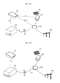
- FIGS. 4A and 4B are perspective views showing various embodiments of an energy storage device in FIG. 1 ;
- FIG. 5 is a perspective view showing a connection of the energy storage device of FIG. 4B ;
- FIG. 6 is a block diagram of the energy storage device in FIG. 1 ;
- FIG. 7 is a block diagram of a power management device in FIG. 1 ;
- FIG. 8 is a block diagram of a mobile terminal in FIG. 1 ;
- FIG. 9 is a flowchart illustrating a method for operating an energy storage device according to an embodiment of the present invention.
- FIG. 10 is a flowchart illustrating a method for operating a power management device according to an embodiment of the present invention.
- FIGS. 11 to 17 are views referred to for description of the operating method of FIG. 9 or 10 .
- module and “unit”
- module and unit are simply used considering the ease of writing this specification and do not have any particular importance or role. Accordingly, the terms “module” and “unit” may be used interchangeably.
- FIG. 1 is a schematic view showing the configuration of a power supply system according to an embodiment of the present invention.
- the power supply system may supply solar power generated by a photovoltaic module 200 , commercial power from a commercial power plant 840 , etc., to an internal power network 50 through a power distributor 820 .
- the power supply system 10 may supply some of powers stored in a plurality of energy storage devices 100 a , 100 b , . . . , 100 e to a power exchange 800 through the power distributor 820 .
- new and renewable powers generated by a variety of new and renewable energy devices may be supplied to the internal power network 50 through the power distributor 820 .
- the power supply system 10 may supply power into a building, but is not limited thereto and may be subjected to a variety of extensions.
- the power supply system 10 may supply power to each home in a collective building or may supply power to each of a plurality of buildings in a certain region. The following description will be mainly given on the assumption that the power supply system 10 supplies power into a single building.
- the power supply system 10 of FIG. 1 may include the internal power network 50 , the plurality of energy storage devices 100 a , 100 b , . . . , 100 e , the photovoltaic module 200 , a junction box 300 for performing conversion of power from the photovoltaic module 200 , a power management device 500 , a network router 550 , and the power distributor 820 .
- a plurality of loads 700 a , 700 b , . . . , 700 e are illustrated as being electrically connected to the internal power network 50 through respective connection terminals 70 a , 70 b , . . . , 70 e connected to the internal power network 50 .
- the energy storage devices 100 a , 100 b , . . . , 100 e are illustrated as being electrically connected to the internal power network 50 through respective connection terminals 60 a , 60 b , . . . , 60 e connected to the internal power network 50 .
- each of them may receive alternating current (AC) power from the internal power network 50 , convert the received AC power into direct current (DC) power and store the converted DC power in a battery pack provided therein.
- AC alternating current
- DC direct current
- each of them may convert DC power stored in the battery pack into AC power and supply the converted AC power to the internal power network 50 .
- the energy storage devices 100 a , 100 b , . . . , 100 e may operate in the discharge mode.
- DC power stored in each of the energy storage devices 100 a , 100 b , . . . , 100 e may be converted into AC power and then supplied to the internal power network 50 . Therefore, each of the loads 700 a , 700 b , . . . , 700 e electrically connected to the internal power network 50 may be stably supplied with AC power even in the event of a power failure.
- each of the energy storage devices 100 a , 100 b , . . . , 100 e will be described later in detail with reference to FIGS. 6 and 9 .
- the charge mode or discharge mode of each of the energy storage devices 100 a , 100 b , . . . , 100 e is performed based on a charge command or discharge command from the power management device 500 .
- the power management device 500 is capable of managing power in the internal power network 50 , and may be called a home energy management system (HEMS).
- HEMS home energy management system
- the power management device 500 may perform wireless data communication with each of the energy storage devices 100 a , 100 b , . . . , 100 e .
- wireless data communication may be performed between the power management device 500 and each of the energy storage devices 100 a , 100 b , . . . , 100 e in a ZigBee communication scheme.
- a WiFi scheme besides the ZigBee communication scheme, may be applied to wireless data communication between the power management device 500 and each of the energy storage devices 100 a , 100 b , . . . , 100 e .
- wireless Bluetooth Radio Frequency Identification (RFID), Infrared Data Association (IrDA), Ultra Wideband (UWB) and Radio Frequency (RF) schemes may be applied.
- RFID Radio Frequency Identification
- IrDA Infrared Data Association
- UWB Ultra Wideband
- RF Radio Frequency
- the power management device 500 may receive power-on information or energy storage amount information from each of the energy storage devices 100 a , 100 b , . . . , 100 e , and transmit a charge command or discharge command to each of the energy storage devices 100 a , 100 b , . . . , 100 e.
- the power management device 500 may perform wireless data communication with the junction box 300 .
- wireless data communication may be performed between the power management device 500 and the junction box 300 in the ZigBee communication scheme.
- communication schemes such as the WiFi scheme, other than the ZigBee communication scheme, may be used. The following description will be mainly given on the assumption that the ZigBee communication scheme is applied to wireless data communication between the power management device 500 and the junction box 300 .
- the power management device 500 may receive, from the junction box 300 , information about solar power generated by the photovoltaic module 200 and then converted by the junction box 300 .
- the power management device 500 may perform wireless data communication with the power distributor 820 .
- wireless data communication may be performed between the power management device 500 and the power distributor 820 in the ZigBee communication scheme.
- communication schemes such as the WiFi scheme, other than the ZigBee communication scheme, may be used. The following description will be mainly given on the assumption that the ZigBee communication scheme is applied to wireless data communication between the power management device 500 and the power distributor 820 .
- the power management device 500 may receive, from the power distributor 820 , information about commercial power supplied from the commercial power plant 840 to the internal power network 50 and information about load power consumed in the internal power network 50 .
- the power management device 500 may perform wireless data communication with each of the loads 700 a , 700 b , . . . , 700 e electrically connected to the internal power network 50 .
- wireless data communication may be performed between the power management device 500 and each of the loads 700 a , 700 b , . . . , 700 e in the ZigBee communication scheme.
- communication schemes such as the WiFi scheme, other than the ZigBee communication scheme, may be used. The following description will be mainly given on the assumption that the ZigBee communication scheme is applied to wireless data communication between the power management device 500 and each of the loads 700 a , 700 b , . . . , 700 e.
- the power management device 500 may receive the information about the load power consumed in the internal power network 50 from the loads 700 a , 700 b , . . . , 700 e.
- the information about the load power consumed in the internal power network 50 may be transmitted from the power distributor 820 or the loads 700 a , 700 b , . . . , 700 e to the power management device 500 as stated above, the following description will be mainly given on the assumption that the information about the load power consumed in the internal power network 50 is transmitted from the power distributor 820 to the power management device 500 .
- the power management device 500 may perform wireless data communication with powered-on ones of the energy storage devices 100 a , 100 b , . . . , 100 e.
- the power management device 500 may receive a pairing request signal, which is power-on information, from a powered-on energy storage device and transmit a pairing response signal including a radio channel allocation signal, etc., to the powered-on energy storage device in response to the received pairing request signal. Then, when pairing with the powered-on energy storage device is completed, the power management device 500 may perform wireless data communication with the powered-on energy storage device over an allocated radio channel.
- a pairing request signal which is power-on information
- a pairing response signal including a radio channel allocation signal, etc.
- the power management device 500 may receive information about solar power generated by the photovoltaic module 200 , information about commercial power supplied to the internal power network 50 , information about load power consumed in the internal power network 50 , and information about an energy storage amount of each of the energy storage devices 100 a , 100 b , . . . , 100 e.
- the power management device 500 may receive the information about the solar power generated by the photovoltaic module 200 from the junction box 300 through ZigBee communication. Also, the power management device 500 may receive the information about the commercial power supplied to the internal power network 50 and the information about the load power consumed in the internal power network from the power distributor 820 through ZigBee communication. Also, the power management device 500 may receive the information about the energy storage amount of each of the energy storage devices 100 a , 100 b , . . . , 100 e from a corresponding one of the energy storage devices 100 a , 100 b , . . . , 100 e through ZigBee communication.
- the energy storage amount information may include information about power stored in a battery pack or information about power additionally storable in the battery pack.
- the power management device 500 may determine that at least one of the energy storage devices 100 a , 100 b , . . . , 100 e will operate in the charge mode, based on at least one of the solar power information, the commercial power information, the load power information and the energy storage amount information, and generate a charge command according to the determined charge mode.
- the power management device 500 may determine that at least one of the energy storage devices 100 a , 100 b , . . . , 100 e will operate in the discharge mode, based on at least one of the solar power information, the commercial power information, the load power information and the energy storage amount information, and generate a discharge command according to the determined discharge mode.
- the power management device 500 may receive information about the power failure from the power distributor 820 , and thus determine that at least one of the energy storage devices 100 a , 100 b , . . . , 100 e will operate in the discharge mode and generate a discharge command according to the determined discharge mode.
- the power management device 500 may transmit the charge command or discharge command to the at least one energy storage device through ZigBee communication.
- the power management device 500 may perform data communication with an external server 570 through the network router 550 , etc.
- the external server 570 may provide information about the price of commercial power, peak time power supply/demand information, etc.
- the external server 570 may receive such information from the power exchange 800 or commercial power plant 840 and transmit the received information to the power management device 500 over an external network 560 .
- the power management device 500 may receive the commercial power price information, the peak time power supply/demand information, etc., and generate the discharge command or charge command in further consideration of the received information in the above discharge command generation or charge command generation.
- the commercial power price information and the peak time power supply/demand information may be received from the power exchange 800 or commercial power plant 840 , besides the external server 570 .
- the network router 550 may exchange data with the power management device 500 and the external network 560 to enable the power management device 500 to be connected with the external network 560 .
- the network router 550 may provide an internal network for the internal power network 50 with the power management device 500 which manages power in the internal power network 50 .
- the network router 550 may be a wireless network router which is capable of performing wireless data communication.
- the network router 550 may be called an access point (AP).
- the network router 550 may allocate radio channels to electronic devices in the internal network and perform wireless data communications with the electronic devices over the corresponding channels. For example, the network router 550 may perform wireless data communication with a mobile terminal 600 b located in the internal network in the WiFi scheme.
- the mobile terminal 600 b located in the internal network may exchange data with the power management device 500 , and perform power information monitoring, remote control for power management, etc., through connection with the power management device 500 .
- the network router 550 may perform data communication with an external electronic device over the external network 560 , besides the internal network.
- the network router 550 may perform wireless data communication with a mobile terminal 600 a located outside of the internal network.
- the network router 550 may be a network access server (NAS).
- NAS network access server
- the mobile terminal 600 a located outside of the internal network may exchange data with the power management device 500 , and perform power information monitoring, remote control for power management, etc., through connection with the power management device 500 .
- the photovoltaic module 200 converts sunlight into DC power and outputs the converted DC power.
- the photovoltaic module 200 may include a plurality of solar cells.
- the photovoltaic module 200 may further include a first sealing member disposed on the bottom of the solar cells, a second sealing member disposed on the top of the solar cells, a rear substrate disposed on the lower surface of the first sealing member, and a front substrate disposed on the upper surface of the second sealing member.
- Each solar cell is a semiconductor device which converts solar energy into electrical energy, and may be a silicon solar cell, a compound semiconductor solar cell, a tandem solar cell, a fuel sensitive solar cell, a CdTe solar cell or a CIGS solar cell.
- the solar cells may be electrically connected in series, in parallel or in series-parallel.
- the junction box 300 receives DC power from the photovoltaic module 200 , converts the received DC power into AC power and outputs the converted AC power.
- the junction box 300 may include a bypass diode, a DC/DC converter, a smoothing capacitor, and an inverter.
- the junction box 300 may further include a communication module for communication with the power management device 500 .
- the junction box 300 may transmit, to the power management device 500 , information about solar power generated by the photovoltaic module 200 and then converted by the junction box 300 .
- the junction box 300 may receive solar power adjustment information from the power management device 500 and adjust solar power to be output based on the received solar power adjustment information.
- solar power output from the junction box 300 is illustrated as being supplied to the internal power network 50 via the power distributor 820 .
- junction box 300 is shown in FIG. 1 as being separate from the photovoltaic module 200 , it may be integrally attached on the rear surface of the photovoltaic module 200 , alternatively.
- FIG. 2 is a schematic view showing the configuration of a power supply system according to another embodiment of the present invention.
- the power supply system of FIG. 2 denoted by reference numeral 10 , is substantially the same in configuration as the power supply system 10 of FIG. 1 , with the exception that the solar power output from the junction box 300 is directly supplied to the internal power network 50 , not via the power distributor 820 .
- FIGS. 3A and 3B are plan views showing various examples of an arrangement of respective devices in the power supply system of FIG. 1 .
- FIG. 3A shows one example of the arrangement of the respective devices in the power supply system of FIG. 1 .
- the power management device 500 among the respective devices in the power supply system 10 , may be disposed in a living room.
- the first energy storage device 100 a may be disposed in the living room, the second energy storage device 100 b in an inner room, the third energy storage device 100 c in a small room, the fourth energy storage device 100 d in a toilet, and the fifth energy storage device 100 e in a kitchen, respectively.
- These energy storage devices 100 a , 100 b , . . . , 100 e may be electrically connected to the internal power network 50 through the respective connection terminals 60 a , 60 b , . . . , 60 e , as stated previously with reference to FIG. 1 .
- a television which is the first load 700 a
- a refrigerator which is the second load 700 b
- a washing machine which is the third load 700 c
- an air conditioner which is the fourth load 700 d
- a cooker which is the fifth load 700 e , in the kitchen, respectively.
- loads 700 a , 700 b , . . . , 700 e may be electrically connected to the internal power network 50 through the respective connection terminals 70 a , 70 b , . . . , 70 e , as stated previously with reference to FIG. 1 .
- the power distributor 820 may be disposed around the gate of an entrance, the photovoltaic module 200 may be disposed at the roof of a building, and the junction box 300 may be disposed in the vicinity of the power distributor 820 , for example, outside of the building.
- the power management device 500 disposed in the living room may perform wireless data communication with each of the energy storage devices 100 a , 100 b , . . . , 100 e through ZigBee communication. Also, the power management device 500 may perform wireless data communication with each of the loads 700 a , 700 b , . . . , 700 e through ZigBee communication. Also, the power management device 500 may perform wireless data communication with the power distributor 820 or junction box 300 through ZigBee communication.
- FIG. 3B shows another example of the arrangement of the respective devices in the power supply system of FIG. 1 .
- the photovoltaic module 200 , junction box 300 , power management device 500 , loads 700 a , 700 b , . . . , 700 e and power distributor 820 among the respective devices of FIG. 3B , may be disposed at the same positions as in FIG. 3A . That is, the photovoltaic module 200 , junction box 300 , power management device 500 , loads 700 a , 700 b , . . . , 700 e and power distributor 820 may be disposed on the first floor.
- the energy storage devices 100 a , 100 b , . . . , 100 e may be separately disposed on a different floor.
- the energy storage devices 100 a , 100 b , . . . , 100 e may be disposed in a basement B 1 , as shown in FIG. 3B .
- the energy storage devices 100 a , 100 b , . . . , 100 e have pluggable sockets, respectively, as will be described below, they may be connected in series as shown in FIG. 3B .
- This arrangement of the energy storage devices 100 a , 100 b , . . . , 100 e on a separate floor enables the use of the energy storage devices 100 a , 100 b , . . . , 100 e without spatial restrictions.
- FIGS. 4A and 4B are perspective views showing various embodiments of each energy storage device in FIG. 1 .
- each energy storage device may include a plug 112 connectable to a socket for electrical connection with the internal power network 50 , and a display unit 105 for displaying a power-on state when the energy storage device 100 is powered on or displaying an energy storage amount, etc., of the energy storage device 100 .
- the display unit 105 enables the user to immediately know the energy storage amount.
- the energy storage device 100 of FIG. 4B is substantially the same as that of FIG. 4A , with the exception that it further includes a socket 125 connectable with the plug 112 .
- This configuration enables electrical connections among energy storage devices.
- the socket 125 is connectable with the plug of a different energy storage device.
- storable DC power may be increased. That is, the storage capacity of DC power storable in the energy storage device 100 may be changed.
- FIG. 5 is a perspective view showing a connection of the energy storage device of FIG. 4B .
- the energy storage devices 100 a , 100 b , . . . , 100 e may be electrically connected in series.
- the plug 112 a of the first energy storage device 100 a may be connected to the socket 125 b of the second energy storage device 100 b
- the plug 112 b of the second energy storage device 100 b may be connected to the socket 125 c of the third energy storage device 100 c .
- the energy storage devices 100 a , 100 b , . . . , 100 e may be electrically connected in series.
- This series connection may correspond to the connection state of the energy storage devices 100 a , 100 b , . . . , 100 e in FIG. 3B .
- the electrical connections among the energy storage devices 100 a , 100 b , . . . , 100 e enable electrical connections among battery packs provided respectively in the energy storage devices 100 a , 100 b , . . . , 100 e , thereby expanding the storage capacity of DC power storable in each energy storage device.
- FIG. 6 is a block diagram of each energy storage device in FIG. 1 .
- the energy storage device 100 may include a connector 130 , a power converter 140 , a communication module 150 , and a built-in battery pack 160 .
- the connector 130 may include only AC power terminals.
- the energy storage device 100 may receive AC power, supplied to the internal power network 50 through the photovoltaic module 200 , based on a charge command from the power management device 500 , or output AC power to the internal power network based on a discharge command from the power management device 500 .
- DC power terminals are not needed and only AC power terminals are provided.
- the power converter 140 upon receiving the charge command from the power management device 500 , may receive AC power from the internal power network 50 and convert the received AC power into DC power, based on the received charge command. Then, the converted DC power may be transferred to the battery pack 160 .
- the power converter 140 upon receiving the discharge command from the power management device 500 , may convert DC power stored in the battery pack 160 into AC power based on the received discharge command. Then, the converted AC power may be transferred to the above-stated internal power network 50 via the connector 130 .
- the power converter 140 may include a bidirectional AC/DC converter which receives AC power from the internal power network 50 and converts the received AC power into DC power, or converts DC power stored in the battery pack 160 into AC power based on the discharge command.
- the communication module 150 performs data communication with the power management device 500 .
- the communication module 150 may transmit power-on information or energy storage amount information to the power management device 500 and receive the charge command or discharge command from the power management device 500 .
- the ZigBee communication scheme among them, will be used for wireless data communication in the present embodiment.
- the communication module 150 may transmit a pairing request signal as power-on information to the power management device 500 . Then, the communication module 150 may receive a pairing response signal including information about a radio channel allocated by the power management device 500 from the power management device 500 . As a result, the communication module 150 may perform wireless data communication with the power management device 500 over a radio channel different from that of another energy storage device.
- the communication module 150 may receive the charge command or discharge command from the power management device 500 . Also, after paring completion, the communication module 150 may transmit information about the amount of energy stored in the battery pack 160 to the power management device 500 .
- the communication module 150 may control the power converter 140 and the battery pack 160 .
- the communication module 150 may control the power converter 140 to convert AC power from the internal power network 50 into DC power. Then, the communication module 150 may control the battery pack 160 to store the converted DC power in the battery pack 160 .
- the communication module 150 may control the battery pack 160 to transfer DC power stored in the battery pack 160 to the power converter 140 . Then, the communication module 150 may control the power converter 140 to convert the DC power transferred to the power converter 140 into AC power.
- the communication module 150 may control the battery pack 160 such that it operates in the charge mode or discharge mode.
- the battery pack 160 may include a battery pack case, and a battery controller 162 , a battery cell unit 164 and a temperature adjuster 166 provided in the battery pack case.
- the battery cell unit 164 includes a plurality of battery cells. These battery cells may be connected in series, in parallel or in series-parallel combination.
- the temperature adjuster 166 adjusts the temperature of the battery cell unit 164 .
- the temperature adjuster 166 may include temperature sensing means or device to sense the temperature of the battery cell unit 164 .
- the temperature adjuster 166 may further include fan driving means or device to drive a fan based on the sensed temperature so as to lower the temperature of the battery cell unit 164 .
- the fan driving means or device is preferably disposed in an area corresponding to an area in which all the battery cells are arranged.
- the battery controller 162 performs the overall control of the battery pack 160 . For example, when the temperature of the battery cell unit 164 rises over a predetermined temperature, the battery controller 162 may control the temperature adjuster 166 to lower the temperature of the battery cell unit 164 .
- the battery controller 162 may balance DC powers stored respectively in the battery cells in the battery cell unit 164 . That is, the battery controller 162 may detect the DC powers stored respectively in the battery cells and balance the DC powers based on a result of the detection.
- the battery controller 162 may transfer status information (a temperature, the level of power stored, etc.) of the battery pack 160 to the communication module 150 . Also, the battery controller 162 may receive status information (the level of power needed, etc.) of the energy storage device 100 from the communication module 150 .
- FIG. 7 is a block diagram of the power management device in FIG. 1 .
- the power management device 500 is a power management device for the internal power network 50 , and may include a communication module 530 , a storage unit 540 , and a processor 520 .
- the communication module 530 in the power management device 500 may wirelessly exchange data with respective devices in the power supply system 10 , for example, the energy storage devices 100 a , 100 b , . . . , 100 e , the junction box 300 and the loads 700 a , 700 b , . . . , 700 e in the ZigBee communication scheme.
- the communication module 530 may include a ZigBee communication module.
- the communication module 530 may receive power-on information or energy storage amount information from each of the energy storage devices 100 a , 100 b , . . . , 100 e and transmit a charge command or discharge command to each of the energy storage devices 100 a , 100 b , . . . , 100 e.
- the communication module 530 may receive a pairing request signal from a powered-on one of the energy storage devices 100 a , 100 b , . . . , 100 e and transmit a pairing response signal generated by the processor 520 to the powered-on energy storage device in response to the received pairing request signal.
- the pairing response signal may include a radio channel allocation signal.
- the communication module 530 may receive, from the junction box 300 , information about solar power generated by the photovoltaic module 200 and then converted by the junction box 300 .
- the communication module 530 may receive, from the power distributor 820 , information about commercial power supplied from the commercial power plant 840 to the internal power network 50 and information about load power consumed in the internal power network 50 .
- the communication module 530 may receive information about the power failure from the power distributor 820 .
- the communication module 530 may receive the information about the load power consumed in the internal power network 50 from the loads 700 a , 700 b , . . . , 700 e.
- the communication module 530 may exchange wireless data with the network router 550 .
- the communication module 530 may exchange the wireless data in the WiFi scheme.
- the communication module 530 may include a WiFi module.
- the communication module 530 may exchange data with the mobile terminal 600 b connected to the internal network or exchange data with the mobile terminal 600 a connected to the external network 560 .
- the processor 520 controls the entire operation of the power management device 500 .
- the power management device 500 may communicate with the energy storage devices 100 a , 100 b , . . . , 100 e to control the energy storage devices 100 a , 100 b , . . . , 100 e such that they operate in the charge mode or discharge mode.
- the processor 520 may determine that at least one of the energy storage devices 100 a , 100 b , . . . , 100 e will operate in the charge mode, based on at least one of the received solar power information, commercial power information, load power information and energy storage amount information, and calculate power to be charged in the at least one energy storage device in the charge mode. Then, the processor 520 may generate a corresponding charge command.
- the processor 520 may determine that at least one of the energy storage devices 100 a , 100 b , . . . , 100 e will operate in the discharge mode, based on at least one of the received solar power information, commercial power information, load power information and energy storage amount information, and calculate power to be discharged from the at least one energy storage device to the internal power network in the discharge mode. Then, the processor 520 may generate a corresponding discharge command.
- the processor 520 may determine that at least one of the energy storage devices 100 a , 100 b , . . . , 100 e will operate in the discharge mode, and generate a discharge command according to the determined discharge mode.
- the processor 520 may monitor power information of at least one of the loads 700 a , 700 b , . . . , 700 e electrically connected to the internal power network 50 or at least one of the energy storage devices 100 a , 100 b , . . . , 100 e electrically connected to the internal power network 50 based on the load power information received from the power distributor 820 or the energy storage amount information received from each of the energy storage devices 100 a , 100 b , . . . , 100 e . That is, the processor 520 may monitor real-time power information.
- the storage unit 540 may store radio channel information for allocation of different radio channels to the energy storage devices 100 a , 100 b , . . . , 100 e .
- the radio channel information may include radio channel names, frequency ranges, security information, etc.
- the storage unit 540 may store device names (device types, device serial numbers, . . . , ), etc., of respective devices wirelessly connected through the power management device 500 .
- the storage unit 540 may store information about a radio channel with the network router 550 .
- the radio channel information may include a radio channel name, a frequency range, security information, etc.
- FIG. 8 is a block diagram of each mobile terminal in FIG. 1 .
- each mobile terminal may include a wireless communication unit 610 , an audio/video (A/V) input unit 620 , a user input unit 630 , a sensing unit 640 , an output unit 650 , a memory 660 , an interface unit 670 , a controller 680 , and a power supply 690 .
- A/V audio/video
- the wireless communication unit 610 may wirelessly exchange data with the power management unit 500 through the network router 550 .
- the wireless communication unit 610 may transmit a power monitoring request and receive monitored information as a result of the power monitoring request.
- the wireless communication unit 610 may transmit a remote control signal.
- the wireless communication unit 610 may receive remote control result information.
- the wireless communication unit 610 may include a broadcast receiving module 611 , a mobile communication module 613 , a wireless Internet module 615 , a near field communication (NFC) module 617 , and a global positioning system (GPS) module 619 .
- a broadcast receiving module 611 may include a broadcast receiving module 611 , a mobile communication module 613 , a wireless Internet module 615 , a near field communication (NFC) module 617 , and a global positioning system (GPS) module 619 .
- NFC near field communication
- GPS global positioning system
- the broadcast receiving module 611 may receive at least one of a broadcast signal and broadcast-related information from an external broadcast management server over a broadcast channel.
- the broadcast channel may include a satellite channel and a terrestrial channel.
- the broadcast signal and/or broadcast-related information received through the broadcast receiving module 611 may be stored in the memory 660 .
- the mobile communication module 613 transmits/receives radio signals to/from at least one of a base station, an external terminal and a server over a mobile communication network.
- the radio signals may include a voice call signal, a video telephony call signal or various forms of data associated with text/multimedia message transmission/reception.
- the wireless Internet module 615 refers to a module for wireless Internet access. This module 615 may be installed inside or outside of the mobile terminal 600 . For example, the wireless Internet module 615 may perform WiFi-based wireless communication or WiFi Direct-based wireless communication.
- the NFC module 617 performs near field communication (NFC).
- NFC near field communication
- the NFC module 617 may receive data from the electronic device or transmit data to the electronic device.
- Such local area communication technologies may include Bluetooth, Radio Frequency Identification (RFID), Infrared Data Association (IrDA), Ultra Wideband (UWB), and ZigBee.
- RFID Radio Frequency Identification
- IrDA Infrared Data Association
- UWB Ultra Wideband
- ZigBee ZigBee
- the GPS module 619 may receive location information from a plurality of GPS satellites.
- the A/V input unit 620 is provided to input an audio signal or video signal.
- the A/V input unit 620 may include a camera 621 and a microphone 623 .
- the user input unit 630 generates key input data that the user inputs to control the operation of the terminal.
- the user input unit 630 may include a key pad, a dome switch, and a touch pad (static pressure/capacitance).
- the touch pad and a display 651 to be described later may form a layered structure, which may be called a touch screen.
- the sensing unit 640 may sense the current state of the mobile terminal 600 , such as the open/closed state of the mobile terminal 600 , the location of the mobile terminal 600 or the presence or absence of user contact with the mobile terminal 600 , and generate a sense signal for control of the operation of the mobile terminal 600 as a result of the sensing.
- the sensing unit 640 may include a proximity sensor 641 , a pressure sensor 643 , and a motion sensor 645 .
- the motion sensor 645 may sense the motion or position of the mobile terminal 600 using an acceleration sensor, a gyro sensor and a gravity sensor.
- the gyro sensor is a sensor which measures an angular velocity, and may sense a direction (angle) in which the mobile terminal 600 is turned relative to a reference direction.
- the output unit 650 may include the display 651 , an audio output module 653 , an alarm unit 655 , and a haptic module 657 .
- the display 651 displays and outputs information processed in the mobile terminal 600 .
- the display 651 and the touch pad form a layered structure to constitute a touch screen
- the display 651 may be used as an input device through which information can be input by user touch, as well as an output device.
- the audio output module 653 outputs audio data received from the wireless communication unit 610 or stored in the memory 660 .
- This audio output module 653 may include a speaker and a buzzer.
- the alarm unit 655 outputs a signal to notify the user of occurrence of an event in the mobile terminal 600 .
- a signal may be output in the form of a vibration.
- the haptic module 657 generates a variety of haptic effects which can be felt by the user.
- a representative example of the haptic effects generated by the haptic module 657 may be a vibration effect.
- the memory 660 may store programs for the processing and control of the controller 680 and may also function to temporarily store input/output data (for example, a phonebook, messages, still images, and moving images).
- input/output data for example, a phonebook, messages, still images, and moving images.
- the interface unit 670 acts to interface with all external devices connected to the mobile terminal 600 .
- the interface unit 670 may receive data transmitted from such an external device or power supplied therefrom and transfer the received data or power to each internal component of the mobile terminal 600 , or transmit internal data of the mobile terminal 600 to the external device.
- the controller 680 typically controls the operation of each of the above-stated components of the mobile terminal 600 , so as to control the overall operation of the mobile terminal 600 .
- the controller 680 may perform control and processing associated with a voice call, data communication, and a video call.
- the controller 680 may include a multimedia playback module 681 for multimedia playback.
- the multimedia playback module 681 may be configured by hardware in the controller 680 or by software separately from the controller 680 .
- the power supply 690 under the control of the controller 680 , receives external power or internal power and supplies power necessary for the operation of each component of the mobile terminal 600 .
- the block diagram of the mobile terminal 600 shown in FIG. 8 is for one embodiment of the present invention.
- the respective components of the block diagram may be combined, added or omitted according to specifications of the mobile terminal 600 which is actually implemented. In other words, as needed, two or more of these components may be combined into one component or one thereof may be subdivided into two or more components.
- the function performed by each block is intended for description of the present embodiment, and the detailed operation or device thereof does not limit the scope of the present invention.
- FIG. 9 is a flowchart illustrating a method for operating an energy storage device according to an embodiment of the present invention
- FIG. 10 is a flowchart illustrating a method for operating a power management device according to an embodiment of the present invention
- FIGS. 11 to 17 are views referred to for description of the operating method of FIG. 9 or 10 .
- the energy storage device 100 determines whether it has been powered on (S 910 ). If the energy storage device 100 has been powered on, it transmits a pairing request signal as power-on information to the power management device 500 (S 920 ). Then, the energy storage device 100 receives a pairing response signal from the power management device 500 (S 930 ).
- FIG. 12A illustrates a state in which the plug 112 of the energy storage device 100 is not connected to a socket 60 .
- FIG. 12B illustrates a state in which the plug 112 of the energy storage device 100 is connected to the socket 60 .
- AC power supplied from the internal power network 50 may be input through the connector 130 and then converted into DC power by the power converter 140 .
- the converted DC power may be supplied as operating power to each module of the energy storage device 100 .
- the communication module 150 may determine that the energy storage device 100 has been powered on, and then transmit the pairing request signal, which indicates that the energy storage device 100 has been powered on, to the power management device 500 .
- the power management device 500 determines whether the pairing request signal has been received (S 1020 ), and transmits the pairing response signal to the corresponding energy storage device 100 upon determining that the pairing request signal has been received (S 1030 ).
- the communication module 530 transfers the pairing request signal received from the energy storage device 100 to the processor 520 . Then, the processor 520 generates the pairing response signal, which includes information about a radio channel allocated to the corresponding energy storage device 100 , in response to the pairing request signal, and then controls the power management device 500 to transmit the generated pairing response signal to the energy storage device 100 through the communication module 530 .
- FIG. 12B also illustrates that the pairing request signal, denoted by Sp 1 , is transmitted from the energy storage device 100 to the power management device 500 and the pairing response signal, denoted by Sp 2 , is transmitted from the power management device 500 to the energy storage device 100 , in the state in which the plug 112 of the energy storage device 100 is connected to the socket 60 .
- step S 1110 of FIG. 11 corresponds to step S 910 of FIG. 9
- step S 1120 of FIG. 11 corresponds to step S 920 of FIG. 9 and step S 1020 of FIG. 10
- step S 1130 of FIG. 11 corresponds to step S 930 of FIG. 9 and step S 1030 of FIG. 10 .
- the power management device 500 receives solar power information from the junction box 300 (S 1031 ). Also, the power management device 500 receives information about load power consumed in the internal power network 50 and information about commercial power supplied to the internal power network 50 from the power distributor 820 (S 1034 ). Also, the power management device 500 receives information about power stored in the energy storage device 100 , namely, information about an energy storage amount of the energy storage device 100 (S 1036 ). Then, the power management device 500 calculates power storable in the energy storage device 100 or power to be output from the energy storage device 100 based on at least one of the load power information, the commercial power information, the solar power information and the energy storage amount information (S 1038 ). Then, the power management device 500 transmits a charge command or discharge command to the energy storage device 100 based on information about the calculated storable power or information about the calculated output power (S 1040 ).
- the communication module 530 of the power management device 500 may receive information about solar power generated by the photovoltaic module 200 and then converted by the junction box 300 from the junction box 300 through ZigBee communication.
- the communication module 530 of the power management device 500 may receive the commercial power information and the load power information from the power distributor 820 through ZigBee communication.
- the load power information may be transmitted from the power distributor 820 .
- the power distributor 820 has a wattmeter which calculates the amount of power consumed in the internal power network 50 , it will calculate load power through the wattmeter.
- Information about the load power calculated by the power distributor 820 may be transmitted to the power management device 500 .
- the communication module 530 of the power management device 500 may receive information about power additionally storable in each of the energy storage devices 100 a , 100 b , . . . , 100 e , namely, information about an energy storage amount of each of the energy storage devices 100 a , 100 b , . . . , 100 e from a corresponding one of the energy storage devices 100 a , 100 b , . . . , 100 e through ZigBee communication.
- FIG. 12C illustrates that energy storage amount information IPes is transmitted from the energy storage device 100 to the power management device 500 . Also, FIG. 12C illustrates that information IPso about solar power generated by the photovoltaic module 200 and then converted by the junction box 300 is transmitted from the junction box 300 to the power management device 500 . Also, FIG. 12C illustrates that information IPco about commercial power supplied to the internal power network 50 and information IP L about load power consumed by each load are transmitted from the power distributor 820 to the power management device 500 .
- the processor 520 of the power management device 500 determines whether each of the energy storage devices 100 a , 100 b , . . . , 100 e will operate in the charge mode or discharge mode, based on at least one of the received solar power information IPso, commercial power information IPco, load power information IP L and energy storage amount information IPes.
- the processor 520 of the power management device 500 may determine that the solar power will be supplied to the internal power network 50 . Then, when the solar power is supplied to the internal power network 50 , the processor 520 of the power management device 500 may determine that each of the energy storage devices 100 a , 100 b , . . . , 100 e will operate in the charge mode.
- the processor 520 of the power management device 500 may determine that the solar power will be supplied to the internal power network 50 .
- the processor 520 of the power management device 500 may calculate power to be stored in each of the energy storage devices 100 a , 100 b , . . . , 100 e . Also, if it is determined that each of the energy storage devices 100 a , 100 b , . . . , 100 e will operate in the discharge mode, the processor 520 may calculate power to be output from each of the energy storage devices 100 a , 100 b , . . . , 100 e to the internal power network 50 .
- all of the energy storage devices 100 a , 100 b , . . . , 100 e may operate in the charge mode or discharge mode, or some of the energy storage devices 100 a , 100 b , . . . , 100 e may operate in the charge mode and the others may operate in the discharge mode.
- information about the power to be stored may include at least one of a charge start command, charge time information and a charge stop command.
- information about the power to be output may include at least one of a discharge start command, discharge time information and a discharge stop command.
- the communication module 530 of the power management device 500 may transmit the charge command to the corresponding energy storage devices in the charge mode. Also, the communication module 530 of the power management device 500 may transmit the discharge command to the corresponding energy storage devices in the discharge mode.
- step S 1131 of FIG. 11 corresponds to step S 1031 of FIG. 10
- step S 1134 of FIG. 11 corresponds to step S 1034 of FIG. 10
- step S 1136 of FIG. 11 corresponds to step S 1036 of FIG. 10
- step S 1138 of FIG. 11 corresponds to step S 1038 of FIG. 10
- step S 1140 of FIG. 11 corresponds to step S 940 of FIG. 9 and step S 1040 of FIG. 10 .
- the communication module 150 of the energy storage device 100 determines whether the charge command has been received from the power management device 500 (S 940 ). If the charge command has been received from the power management device 500 , the energy storage device 100 receives AC power from the internal power network 50 based on the received charge command, converts the received AC power into DC power and stores the converted DC power in the battery pack 160 (S 950 ).
- FIG. 12D illustrates that the charge command, denoted by IPps, is transmitted from the power management device 500 to the energy storage device 100 .
- the communication module 150 of the energy storage device 100 may control the energy storage device 100 such that AC power from the internal power network 50 is input through the connector 130 and then converted into DC power by the power converter 140 . Then, the communication module 150 may control the energy storage device 100 to store the converted DC power in the battery pack 160 .
- the solar power supplied to the internal power network 50 may be simply stored in the battery pack 160 .
- FIG. 12E illustrates that power Pps, namely AC power, corresponding to the charge command IPps is supplied from the internal power network 50 to the energy storage device 100 .
- step S 1150 of FIG. 11 corresponds to step S 950 of FIG. 9 .
- the communication module 150 of the energy storage device 100 determines whether the charge stop command has been received from the power management device 500 (S 953 ). If the charge stop command has been received from the power management device 500 , the energy storage device 100 stops the input of the AC power from the internal power network 50 based on the received charge stop command (S 956 ).
- the solar power supplied to the internal power network 50 may not be stored in the battery pack 160 any longer.
- step S 1153 and step S 1156 of FIG. 11 correspond to step S 953 and step S 956 of FIG. 9 , respectively.
- the communication module 150 of the energy storage device 100 determines whether the discharge command has been received from the power management device 500 (S 960 ). If the discharge command has been received from the power management device 500 , the energy storage device 100 converts DC power stored in the battery pack 160 into AC power based on the received discharge command and outputs the converted AC power to the internal power network 50 (S 970 ).
- FIG. 12F illustrates that the discharge command, denoted by IPpo, is transmitted from the power management device 500 to the energy storage device 100 .
- the communication module 150 of the energy storage device 100 may control the energy storage device 100 such that DC power stored in the battery pack 160 corresponding to the power to be output is supplied to the power converter 140 . Then, the communication module 150 may control the energy storage device 100 such that the supplied DC power is converted into AC power by the power converter 140 . Therefore, the DC power stored in the battery pack 160 may be simply converted and then supplied to the internal power network 50 .
- FIG. 12G illustrates that power Ppo, namely AC power, corresponding to the discharge command IPpo is supplied from the energy storage device 100 to the internal power network 50 .
- the communication module 150 of the energy storage device 100 determines whether the discharge stop command has been received from the power management device 500 (S 973 ). If the discharge stop command has been received from the power management device 500 , the energy storage device 100 stops the output of the AC power to the internal power network 50 based on the received discharge stop command (S 976 ).
- power stored in the energy storage device 100 is supplied to the internal power network 50 , thereby reducing consumption of commercial AC power. That is, renewable energy, such as solar power from the photovoltaic module 200 , is stored in the energy storage device 100 and then supplied to the internal power network 50 , so that the energy may be efficiently consumed. Also, because the consumption of the commercial AC power is reduced, the cost thereof is thus reduced.
- the power management device 500 may recognize the energy storage device addition or removal, receive information about the added or removed energy storage device and update the existing information with the received information.
- the power management device 500 may perform pairing, etc., with the added energy storage device to newly store information about the added energy storage device, and allocate a radio channel for wireless data communication to the added energy storage device.
- the power management device 500 may recognize that the existing energy storage device corresponding to the radio channel has been powered off, and update information about the powered-off energy storage device.
- the power management device 500 may perform a control operation based on information about solar power generated by the photovoltaic module 200 , information about commercial power supplied to the internal power network 50 , information about load power consumed in the internal power network 50 , etc., such that the commercial power is used at the minimum and the solar power is used at the maximum. That is, the power management device 500 may provide corresponding information to the power distributor 820 such that all of the solar power is supplied to the internal power network 50 , and provide corresponding information to the power distributor 820 such that only a minimum amount of the commercial power is supplied to the internal power network 50 in consideration of the internal load power information.
- the power management device 500 may provide a smart grid service. That is, in the instance where the price of the commercial power is different according to time zones, the power management device 500 may perform a control operation such that the commercial power is supplied to the internal power network 50 at a time zone at which the commercial power is cheap. Also, the power management device 500 may perform a control operation such that the commercial power supplied to the internal power network 50 is stored in each energy storage device.
- the power management device 500 may perform a control operation such that power stored in an energy storage device is supplied to the internal power network 50 at a time zone at which the commercial power is expensive.
- commercial power price information may be transmitted from the external server 570 to the power management device 500 or transmitted to the power management device 500 through the power exchange 800 or power distributor 820 .
- FIGS. 13A to 13E correspond to FIGS. 12C to 12G , respectively, with the difference that the power management device 500 receives or transmits information from or to a plurality of energy storage devices.
- FIG. 13A illustrates that energy storage amount information IPes 1 , IPes 2 , . . . , IPes 5 are transmitted from the respective energy storage devices 100 a , 100 b , . . . , 100 e to the power management device 500 .
- FIG. 13A illustrates that information IPso about solar power generated by the photovoltaic module 200 is transmitted from the junction box 300 to the power management device 500 and information IPco about commercial power supplied to the internal power network 50 and information IP L about load power consumed by each load are transmitted from the power distributor 820 to the power management device 500 .
- FIG. 13B illustrates that charge commands IPps 1 , IPps 2 , . . . , IPps 5 are transmitted from the power management device 500 to the respective energy storage devices 100 a , 100 b , . . . , 100 e.
- FIG. 13C illustrates that powers Pps 1 , Pps 2 , . . . , Pps 5 , namely AC powers, corresponding respectively to the charge commands IPps 1 , IPps 2 , . . . , IPps 5 are supplied from the internal power network 50 to the respective energy storage devices 100 a , 100 b , . . . , 100 e.
- FIG. 13D illustrates that discharge commands IPpo 1 , IPpo 2 , . . . , IPpo 5 are transmitted from the power management device 500 to the respective energy storage devices 100 a , 100 b , . . . , 100 e.
- FIG. 13E illustrates that powers Ppo 1 , Ppo 2 , . . . , Ppo 5 , namely AC powers, corresponding respectively to the discharge commands IPpo 1 , IPpo 2 , . . . , IPpo 5 are supplied from the respective energy storage devices 100 a , 100 b , . . . , 100 e to the internal power network 50 .
- all of the energy storage devices 100 a , 100 b , . . . , 100 e may operate in the charge mode as shown in FIG. 13C or in the discharge mode as shown in FIG. 13E .
- some of the energy storage devices 100 a , 100 b , . . . , 100 e may operate in the discharge mode and the others may operate in the charge mode.
- FIG. 13F illustrates that the charge command IPps 1 and the discharge commands IPpo 2 , . . . , IPpo 5 are transmitted from the power management device 500 to the respective energy storage devices 100 a , 100 b , . . . , 100 e.
- FIG. 13G illustrates that the power Pps 1 , namely AC power, corresponding to the charge command IPps 1 is supplied from the internal power network 50 to the first energy storage device 100 a . Also, FIG. 13G illustrates that the powers Ppo 2 , . . . , Ppo 5 , namely AC powers, corresponding respectively to the discharge commands IPpo 2 , . . . , IPpo 5 are supplied from the second to fifth energy storage devices 100 a , 100 b , . . . , 100 e to the internal power network 50 .
- the powers Ppo 2 , . . . , Ppo 5 namely AC powers, corresponding respectively to the discharge commands IPpo 2 , . . . , IPpo 5 are supplied from the second to fifth energy storage devices 100 a , 100 b , . . . , 100 e to the internal power network 50 .
- the power supply system 10 may supply some of the power stored in the energy storage device 100 to the power exchange 800 through the power distributor 820 .
- the processor 520 of the power management device 500 may calculate power to be output to the outside of the internal power network 50 based on at least one of the load power information IP L , the commercial power information IPco, the solar power information Ipso and the energy storage amount information of each energy storage device. That is, the processor 520 may calculate external output power to be transmitted to the power exchange 800 .
- the communication module 530 of the power management device 500 may transmit information about the calculated external output power to the power distributor 820 , which distributes the commercial power to the internal power network 50 .
- the energy storage device 100 may supply AC power to the internal power network 50 in the discharge mode, and the power distributor 820 may perform a control operation such that some of the AC power supplied to the internal power network 50 is output externally, particularly to the power exchange 800 .
- FIG. 14A illustrates that the external output power information, denoted by IPdi, is transmitted to the power distributor 820 .
- FIG. 14B illustrates that external output power Pdi, namely AC power, corresponding to the external output power information IPdi is transmitted from the power distributor 820 to the power exchange 800 . Therefore, it may be possible to use power efficiently.
- the plurality of energy storage devices 100 a , 100 b , . . . , 100 e and the plurality of loads 700 a , 700 b , . . . , 700 e in the power supply system 10 according to the present embodiment are shown as one-to-one corresponding to each other, alternatively, a plurality of loads may be assigned to one energy storage device to correspond thereto. In particular, one energy storage device may correspond to loads adjacent thereto.
- one energy storage device may supply power stored therein to the internal power network 50 according to power consumption of a plurality of loads, and the corresponding loads may immediately consume AC power supplied from the energy storage device. That is, in the power supply system 10 , an energy storage device corresponding to a local position where power consumption is required may operate in the discharge mode, thereby making it possible to efficiently manage power.
- the power management device 500 may store information about the position of each energy storage device, information about the position of each load, and information about power consumption of each load.
- the information about the position of each energy storage device may be calculated based on the strength of a signal, etc., when pairing with the corresponding energy storage device is performed. Also, the information about the position of each load may be calculated based on the strength of a signal, etc., when pairing between the corresponding load and the power management device 500 is performed.
- FIGS. 16 and 17 are views referred to for description of a power monitoring mode and a remote control mode through a mobile terminal.
- FIG. 16 illustrates the power monitoring mode through the mobile terminal 600 .
- the mobile terminal 600 may enter the power monitoring mode for the internal power network 50 when an associated menu of the mobile terminal 600 is executed or an associated application of the mobile terminal 600 is run.
- FIG. 16 illustrates a power monitoring picture 1610 displayed when the power monitoring mode is entered.
- the power monitoring picture 1610 is provided for monitoring of power in the internal power network 50 , and is illustrated in the drawing as including a whole mode item 1615 and an individual mode item 1618 .
- the wireless communication unit 610 of the mobile terminal 600 may transmit a power monitoring request to the power management device 500 over the internal network or external network 560 .
- the wireless communication unit 610 may transmit a power monitoring request for the whole of the internal power network 50 .
- the power management device 500 may transmit monitored information for the whole of the internal power network 50 , and the wireless communication unit 610 of the mobile terminal 600 may receive the transmitted monitored information and deliver the received monitored information to the controller 680 . Then, the controller 680 may perform a control operation to display the monitored information in a whole mode through the display.
- FIG. 16 illustrates a whole mode picture 1620 .
- (b) of FIG. 16 illustrates that icons indicating energy storage amounts of energy storage devices ESS 1 , ESS 2 , ESS 3 and ESS 4 are displayed in a plan view 1625 of a house. Therefore, the user may intuitively check the energy storage amounts of the energy storage devices located in the house.
- icons indicating energy consumption amounts of loads may further be displayed.
- an individual mode picture 1630 may be displayed on the display of the mobile terminal 600 , as shown in (c) of FIG. 16 .
- the number of energy storage devices electrically connected to the internal power network 50 is illustrated as being four.
- the wireless communication unit 610 of the mobile terminal 600 may transmit a power monitoring request for a first energy storage device to the power management device 500 over the internal network or external network 560 . That is, the wireless communication unit 610 may transmit request information about an energy storage amount of the first energy storage device.
- the power management device 500 may transmit the information about the energy storage amount of the first energy storage device as monitored information, and the wireless communication unit 610 of the mobile terminal 600 may receive the transmitted monitored information and deliver the received monitored information to the controller 680 . Then, the controller 680 may perform a control operation to display the monitored information through the display.
- FIG. 16 illustrates an individual mode picture 1640 .
- (d) of FIG. 16 illustrates that an object 1642 indicating the energy storage amount information of the first energy storage device is displayed.
- the user may intuitively check the energy storage amount of the first energy storage device located in the house.
- FIG. 17 illustrates the remote control mode through the mobile terminal 600 .
- the mobile terminal 600 may enter the remote control mode for the internal power network 50 when an associated menu of the mobile terminal 600 is executed or an associated application of the mobile terminal 600 is run.
- FIG. 17 illustrates a remote control picture 1710 displayed when the remote control mode is entered.
- the remote control picture 1710 is provided for remote control of the power management device 500 , etc., and is illustrated in the drawing as including a whole mode item 1715 and an individual mode item 1718 .
- a whole mode picture 1720 may be displayed as shown in (b) of FIG. 17 .
- the whole mode picture 1720 may include a charge item 1725 for charging of all of a plurality of energy storage devices electrically connected to the internal power network 50 , and a discharge item 1728 for discharging of all of the energy storage devices.
- the wireless communication unit 610 of the mobile terminal 600 may transmit a remote control signal, which instructs the power management device 500 to charge all the energy storage devices, to the power management device 500 over the internal network or external network 560 .
- an individual mode picture 1730 may be displayed on the display of the mobile terminal 600 , as shown in (c) of FIG. 17 .
- the number of energy storage devices electrically connected to the internal power network 50 is illustrated as being four.
- a remote control picture 1740 for a first energy storage device ESS 1 may be displayed as shown in (d) of FIG. 17 .
- the remote control picture 1740 may include a charge item 1745 for charging of the first energy storage device ESS 1 , and a discharge item 1748 for discharging of the first energy storage device ESS 1 .
- the wireless communication unit 610 of the mobile terminal 600 may transmit a remote control signal, which instructs the power management device 500 to charge the first energy storage device ESS 1 , to the power management device 500 over the internal network or external network 560 .
- the user may remotely control the power management device 500 or energy storage device simply and conveniently.
- the energy storage device, the power management device, the mobile terminal and the method for operating the same according to the present invention are not limited to the configurations and methods of the above-described embodiments, and all or some of these embodiments may be selectively combined and configured so that those embodiments may be subjected to various modifications.
- the energy storage device operating method or power management device operating method of the embodiment of the present invention may be implemented in a recording medium readable by the processor of the energy storage device or power management device by processor-readable codes.
- the processor-readable recording medium may include all types of recording units in which processor-readable data may be stored.
- the processor-readable recording medium may include a ROM, a RAM, a CD-ROM, a magnetic tape, a floppy disk, an optical data storage, or the like.
- the processor-readable recording medium may be distributed to networked computer systems and processor-readable codes may be stored and executed in the computer systems in a distributed manner.
- an energy storage device may, based on a charge command or discharge command received from a power management device, convert AC power from an internal power network into DC power and store the converted DC power, or convert DC power stored therein into AC power and output the converted AC power to the internal power network. Therefore, it may be possible to efficiently store energy in the energy storage device.
- a power converter of the energy storage device includes a bidirectional converter for receiving AC power and converting the received AC power into DC power, or converting DC power stored in a battery pack into AC power and outputting the converted AC power.
- the power converter requires no separate DC/DC converter, so that it may be simply configured.
- the energy storage device when the energy storage device is powered on, it may perform pairing with the power management device to operate under control of the power management device, thereby increasing user convenience.
- the power management device may perform pairing with the powered-on energy storage device, thereby simply controlling energy storage devices provided in the same internal power network.
- the power management device may allocate different radio channels to a plurality of energy storage devices, so as to efficiently control the respective energy storage devices.
- the power management device may generate a charge command or discharge command based on at least one of information about solar power generated by a photovoltaic module, information about commercial power supplied to the internal power network, information about load power consumed in the internal power network and information about an energy storage amount of an energy storage device, and transmit the generated charge command or discharge command to the energy storage device. Therefore, the power management device may efficiently control energy storage devices connected to the internal power network.
- the power management device may calculate power to be output to the outside of the internal power network based on at least one of the information about the solar power generated by the photovoltaic module, the information about the commercial power supplied to the internal power network, the information about the load power consumed in the internal power network and the information about the energy storage amount of the energy storage device, and transmit information about the calculated output power to a power distributor connected to the internal power network, so as to control the power distributor such that the corresponding power is externally output.
Landscapes
- Engineering & Computer Science (AREA)
- Power Engineering (AREA)
- Computer Networks & Wireless Communication (AREA)
- Business, Economics & Management (AREA)
- Emergency Management (AREA)
- Human Computer Interaction (AREA)
- Signal Processing (AREA)
- General Physics & Mathematics (AREA)
- Physics & Mathematics (AREA)
- Charge And Discharge Circuits For Batteries Or The Like (AREA)
- Supply And Distribution Of Alternating Current (AREA)
- Remote Monitoring And Control Of Power-Distribution Networks (AREA)
- Secondary Cells (AREA)
Priority Applications (1)
| Application Number | Priority Date | Filing Date | Title |
|---|---|---|---|
| US15/271,287 US10170916B2 (en) | 2012-08-17 | 2016-09-21 | Energy storage device, power management device, mobile terminal and method for operating the same |
Applications Claiming Priority (2)
| Application Number | Priority Date | Filing Date | Title |
|---|---|---|---|
| KR10-2012-0089961 | 2012-08-17 | ||
| KR1020120089961A KR20140023125A (ko) | 2012-08-17 | 2012-08-17 | 에너지 저장장치, 전력 관리 장치, 이동 단말기 및 그 동작방법 |
Related Child Applications (1)
| Application Number | Title | Priority Date | Filing Date |
|---|---|---|---|
| US15/271,287 Division US10170916B2 (en) | 2012-08-17 | 2016-09-21 | Energy storage device, power management device, mobile terminal and method for operating the same |
Publications (2)
| Publication Number | Publication Date |
|---|---|
| US20140049886A1 US20140049886A1 (en) | 2014-02-20 |
| US9490635B2 true US9490635B2 (en) | 2016-11-08 |
Family
ID=48951295
Family Applications (2)
| Application Number | Title | Priority Date | Filing Date |
|---|---|---|---|
| US13/969,189 Active 2034-07-22 US9490635B2 (en) | 2012-08-17 | 2013-08-16 | Energy storage device, power management device, mobile terminal and method for operating the same |
| US15/271,287 Active 2033-11-07 US10170916B2 (en) | 2012-08-17 | 2016-09-21 | Energy storage device, power management device, mobile terminal and method for operating the same |
Family Applications After (1)
| Application Number | Title | Priority Date | Filing Date |
|---|---|---|---|
| US15/271,287 Active 2033-11-07 US10170916B2 (en) | 2012-08-17 | 2016-09-21 | Energy storage device, power management device, mobile terminal and method for operating the same |
Country Status (4)
| Country | Link |
|---|---|
| US (2) | US9490635B2 (fr) |
| EP (1) | EP2698896B1 (fr) |
| JP (1) | JP5992877B2 (fr) |
| KR (1) | KR20140023125A (fr) |
Cited By (4)
| Publication number | Priority date | Publication date | Assignee | Title |
|---|---|---|---|---|
| US11025090B2 (en) | 2016-03-02 | 2021-06-01 | International Business Machines Corporation | Determining location and disruption sequence of power outages |
| US11929622B2 (en) | 2018-08-29 | 2024-03-12 | Sean Walsh | Optimization and management of renewable energy source based power supply for execution of high computational workloads |
| US11962157B2 (en) | 2018-08-29 | 2024-04-16 | Sean Walsh | Solar power distribution and management for high computational workloads |
| US11967826B2 (en) | 2017-12-05 | 2024-04-23 | Sean Walsh | Optimization and management of power supply from an energy storage device charged by a renewable energy source in a high computational workload environment |
Families Citing this family (36)
| Publication number | Priority date | Publication date | Assignee | Title |
|---|---|---|---|---|
| US9281688B2 (en) * | 2013-02-14 | 2016-03-08 | Bradley Hardin | Energy management system for multiple power inputs |
| KR101642178B1 (ko) | 2013-07-02 | 2016-07-25 | 한온시스템 주식회사 | 스크롤 압축기 |
| JP6004451B2 (ja) | 2014-03-26 | 2016-10-05 | インターナショナル・ビジネス・マシーンズ・コーポレーションInternational Business Machines Corporation | データセンター、データセンター間での負荷分散方法 |
| KR102270104B1 (ko) * | 2014-08-14 | 2021-06-25 | 엘지전자 주식회사 | 에너지 저장장치 및 이를 구비하는 에너지 저장 시스템 |
| US10003194B2 (en) | 2014-10-24 | 2018-06-19 | Enphase Energy, Inc. | Parallel battery system |
| WO2016121270A1 (fr) * | 2015-01-30 | 2016-08-04 | ソニー株式会社 | Dispositif de commande, procédé de commande et programme informatique |
| US20160276851A1 (en) * | 2015-03-16 | 2016-09-22 | Unitronics Automated Solutions Ltd. | System and method for managing batteries used in a distributed facility |
| WO2016152264A1 (fr) * | 2015-03-24 | 2016-09-29 | 古野電気株式会社 | Dispositif d'alimentation électrique |
| US9991732B2 (en) * | 2015-04-10 | 2018-06-05 | Enovate Medical Llc | Contactless battery system utilizing a bidirectional power converter |
| KR102364320B1 (ko) * | 2015-04-13 | 2022-02-18 | 엘에스일렉트릭(주) | 에너지 저장 시스템의 모니터링 및 제어 시스템 |
| TWI568128B (zh) * | 2015-06-17 | 2017-01-21 | 圓展科技股份有限公司 | 充電系統及其行動充電裝置與電源供應裝置 |
| KR102440975B1 (ko) * | 2016-01-21 | 2022-09-07 | 삼성전자주식회사 | 전자 장치 및 전자 장치에서 근거리 무선 통신을 위한 방법 |
| KR102527794B1 (ko) * | 2016-02-04 | 2023-05-03 | 삼성전자주식회사 | 코일을 포함하는 전자 장치 |
| US9990002B2 (en) | 2016-05-25 | 2018-06-05 | Lg Electronics Inc. | Sound output apparatus and hub for communication network |
| US10111345B2 (en) | 2016-05-25 | 2018-10-23 | Lg Electronics Inc. | Sound output apparatus and hub for communication network |
| US10440456B2 (en) | 2016-05-25 | 2019-10-08 | Lg Electronics Inc. | Artificial intelligence sound output apparatus, hub for communication network, and method of manufacturing the apparatus and grille for the apparatus |
| US10149080B2 (en) | 2016-05-25 | 2018-12-04 | Lg Electronics Inc. | Method of manufacturing sound output apparatus and method of manufacturing grille for the apparatus |
| US9992036B2 (en) | 2016-05-25 | 2018-06-05 | Lg Electronics Inc. | Sound output apparatus and hub for communication network |
| US10204513B2 (en) | 2016-05-25 | 2019-02-12 | Lg Electronics Inc. | Accessory having a communication function for Internet of Things |
| US10110974B2 (en) | 2016-05-25 | 2018-10-23 | Lg Electronics Inc. | Accessory having a communication function for internet of things |
| US10356499B2 (en) | 2016-05-25 | 2019-07-16 | Lg Electronics Inc. | Artificial intelligence sound output apparatus, hub for communication network, method of manufacturing the apparatus, and grille for the apparatus |
| US10139856B2 (en) * | 2016-05-25 | 2018-11-27 | Lg Electronics Inc. | Accessory assembly |
| US10139857B2 (en) | 2016-05-25 | 2018-11-27 | Lg Electronics Inc. | Accessory |
| US10146255B2 (en) | 2016-05-25 | 2018-12-04 | Lg Electronics Inc. | Accessory communication device |
| US10097640B2 (en) | 2016-05-25 | 2018-10-09 | Lg Electronics Inc. | Accessory having a communication function for internet of things |
| KR102610440B1 (ko) * | 2016-08-08 | 2023-12-06 | 상라오 징코 솔라 테크놀러지 디벨롭먼트 컴퍼니, 리미티드 | 태양광 모듈, 및 이를 구비하는 태양광 시스템 |
| EP3619788A1 (fr) * | 2017-05-03 | 2020-03-11 | Wattdock UG (Haftungsbeschränkt) | Dispositif et système de stockage d'énergie électrique modulaire |
| KR102514763B1 (ko) * | 2017-07-25 | 2023-03-28 | 삼성전자주식회사 | 입력 장치 활용 방법 및 이를 구현한 전자 장치 |
| KR102457190B1 (ko) * | 2017-08-30 | 2022-10-21 | 한국전자통신연구원 | 에너지 하베스팅 기반의 에너지 관리 장치 |
| KR102039703B1 (ko) * | 2017-12-26 | 2019-11-01 | 김성두 | 충전 장치 |
| CN109546747B (zh) * | 2018-10-29 | 2021-01-22 | 国网河南省电力公司濮阳供电公司 | 一种智能化输配电网故障预警管理系统 |
| CN109599944A (zh) * | 2018-11-29 | 2019-04-09 | 浙江涵普电力科技有限公司 | 智能配变终端 |
| US20220102998A1 (en) * | 2020-09-30 | 2022-03-31 | BluWave Inc. | Systems and methods for efficient charging of energy storage systems |
| CN113300740A (zh) * | 2021-05-18 | 2021-08-24 | 福建工程学院 | 基于三大电信运营商的电力系统监控通信系统及方法 |
| KR102637098B1 (ko) * | 2022-10-06 | 2024-02-27 | 주식회사 넘버제로 | 역학적 에너지를 활용한 에너지 저장 장치 |
| KR102540658B1 (ko) * | 2022-10-12 | 2023-06-08 | (주)미섬시스텍 | 범용성을 높인 pms 및 그 제어방법 |
Citations (40)
| Publication number | Priority date | Publication date | Assignee | Title |
|---|---|---|---|---|
| US4383211A (en) * | 1981-01-02 | 1983-05-10 | Atlantic Richfield Company | Electrical charging and discharging control apparatus and method, and solar to electrical energy conversion apparatus incorporating such apparatus |
| US4636931A (en) * | 1985-06-28 | 1987-01-13 | Shikoku Denryoku Kabushiki Kaisha | Photovoltaic power control system |
| JPH03190538A (ja) * | 1989-12-14 | 1991-08-20 | Toshiba Corp | 蓄電池充電装置 |
| JPH09163626A (ja) * | 1995-12-11 | 1997-06-20 | Sanyo Electric Co Ltd | 太陽光発電装置 |
| JPH1014128A (ja) * | 1996-06-24 | 1998-01-16 | Sanyo Electric Co Ltd | 系統連系電源システム及び電源システム |
| US5751133A (en) * | 1995-03-29 | 1998-05-12 | Canon Kabushiki Kaisha | Charge/discharge control method, charge/discharge controller, and power generation system with charge/discharge controller |
| JP2000004545A (ja) * | 1998-06-15 | 2000-01-07 | Sumitomo Electric Ind Ltd | 電源電力供給総合管理システム |
| US20030202344A1 (en) * | 2002-04-30 | 2003-10-30 | G-5 Electronics | System and method of power management for a solar powered device |
| US20040066094A1 (en) * | 2002-08-01 | 2004-04-08 | Yasunobu Suzuki | Co-generated power supply system |
| US20080040223A1 (en) * | 2006-08-10 | 2008-02-14 | V2 Green Inc. | Electric Resource Module in a Power Aggregation System for Distributed Electric Resources |
| JP2008043170A (ja) | 2006-08-10 | 2008-02-21 | Nippon Telegr & Teleph Corp <Ntt> | 電力供給システム、需用家群設備、およびその監視制御方法 |
| US20080167756A1 (en) * | 2007-01-03 | 2008-07-10 | Gridpoint, Inc. | Utility console for controlling energy resources |
| JP2008182851A (ja) | 2007-01-25 | 2008-08-07 | Chugoku Electric Power Co Inc:The | 電力貯蔵装置及びシステム |
| JP2009302030A (ja) | 2008-06-17 | 2009-12-24 | Kazumasa Sakakibara | 電池パック |
| WO2009157342A1 (fr) | 2008-06-27 | 2009-12-30 | シャープ株式会社 | Système de commande de puissance destiné à distribuer de la puissance à des installations la nécessitant |
| US20100076825A1 (en) * | 2008-09-25 | 2010-03-25 | Hitachi, Ltd. | Charge/discharge control apparatus |
| US20100138066A1 (en) * | 2008-11-14 | 2010-06-03 | Thinkeco Power Inc. | System and method of democratizing power to create a meta-exchange |
| US20110078092A1 (en) * | 2009-09-25 | 2011-03-31 | Lg Electronics Inc. | Apparatus and method for controlling a battery |
| US20110074356A1 (en) * | 2006-06-15 | 2011-03-31 | Mitsumi Electric Co. Ltd. | Charge and Discharge Circuit of Secondary Battery and Battery Pack |
| US20110133556A1 (en) | 2009-12-04 | 2011-06-09 | Samsung Sdi Co., Ltd. | Energy storage system |
| US20110153098A1 (en) * | 2009-12-21 | 2011-06-23 | Hitachi, Ltd. | Renewable electricity generation system, electric power measurement device and method |
| EP2346138A2 (fr) | 2010-01-18 | 2011-07-20 | Samsung SDI Co., Ltd. | Appareil de stockage de puissance |
| JP2011185662A (ja) | 2010-03-05 | 2011-09-22 | Sony Corp | 電子機器、バッテリーパック、機器システム、バッテリーパック冷却部の制御方法及びプログラム |
| US20110291479A1 (en) | 2010-06-01 | 2011-12-01 | Samsung Sdi Co., Ltd. | Energy storage system and method of controlling the same |
| DE102010017264A1 (de) | 2010-06-07 | 2011-12-08 | Entrason Gmbh | System zur Steuerung des Energiehaushalts eines Gebäudes |
| US20120056588A1 (en) * | 2010-09-06 | 2012-03-08 | Eric James Cai | Use of Battery Energy for Power Grid Optimization and Electric Vehicle Charging |
| WO2012036086A1 (fr) | 2010-09-14 | 2012-03-22 | ソニー株式会社 | Groupe d'unités de stockage de charge, chargeur, dispositif électronique, véhicule entraîné électriquement, procédé de chargement et procédé de déchargement d'un groupe d'unités de stockage de charge, procédé d'amenée/de réception de courant électrique, et procédé de détermination d'un itinéraire de charge/de décharge dans le groupe d'unités de stockage de charge |
| JP2012100429A (ja) | 2010-11-02 | 2012-05-24 | Toyota Motor Corp | 給電管理システム |
| WO2012066915A1 (fr) | 2010-11-19 | 2012-05-24 | 株式会社日立製作所 | Dispositif de commande pour dispositif de stockage électrique, dispositif de stockage électrique, et procédé de chargement destiné à charger/décharger un dispositif de stockage électrique |
| US20120161523A1 (en) | 2010-12-28 | 2012-06-28 | Lg Electronics Inc. | Photovoltaic power generation system |
| US20120161709A1 (en) * | 2010-12-22 | 2012-06-28 | Denso Corporation | Secondary-battery control apparatus |
| US20120212183A1 (en) * | 2010-08-23 | 2012-08-23 | Sanyo Electric Co., Ltd. | Power management system |
| US20120228941A1 (en) * | 2010-03-25 | 2012-09-13 | Sanyo Electric Co., Ltd. | Electric power supply system, master control device, system stabilization system, control method for the master control device and control program for the master control device |
| US20120228943A1 (en) * | 2010-10-15 | 2012-09-13 | Sanyo Electric Co., Ltd. | Electric power supply system |
| US20120235491A1 (en) * | 2010-10-15 | 2012-09-20 | Sanyo Electric Co., Ltd. | Prioritization circuit and electric power supply system |
| US20120263151A1 (en) * | 2001-05-14 | 2012-10-18 | Interdigital Technology Corporation | Dynamic channel quality measurement procedure implemented in a wireless digital communication system to prioritize the forwarding of downlink data |
| US20130190939A1 (en) * | 2012-01-20 | 2013-07-25 | Carl J. S. Lenox | Methods and apparatus for dispatching electrical energy from distributed energy resources |
| US20130229057A1 (en) * | 2010-11-02 | 2013-09-05 | Sanyo Electric Co., Ltd. | Control apparatus |
| US20140351010A1 (en) * | 2008-11-14 | 2014-11-27 | Thinkeco Power Inc. | System and method of democratizing power to create a meta-exchange |
| US9065296B2 (en) * | 2012-04-03 | 2015-06-23 | Samsung Sdi Co., Ltd. | Battery pack, method of measuring voltage of the battery pack, and energy storage system including the battery pack |
Family Cites Families (14)
| Publication number | Priority date | Publication date | Assignee | Title |
|---|---|---|---|---|
| JP3620651B2 (ja) * | 2002-05-31 | 2005-02-16 | 東日本旅客鉄道株式会社 | 部材の接合構造 |
| EP1785964A1 (fr) * | 2004-12-06 | 2007-05-16 | Alan G. Spark | Système d'alarme anti-panique de véhicule automobile pour contrer une attaque, et son procédé |
| JP2007060826A (ja) * | 2005-08-25 | 2007-03-08 | Shimizu Corp | 電力貯蔵装置の運用システム |
| JP5070882B2 (ja) * | 2007-02-28 | 2012-11-14 | オムロン株式会社 | 電力供給システムおよび電力供給方法 |
| TW200919894A (en) * | 2007-10-17 | 2009-05-01 | J Tek Inc | High-reliability intelligent parallel-connected energy storage vessel charging/discharging management system |
| US8872379B2 (en) * | 2007-11-30 | 2014-10-28 | Johnson Controls Technology Company | Efficient usage, storage, and sharing of energy in buildings, vehicles, and equipment |
| US8626367B2 (en) * | 2010-02-24 | 2014-01-07 | GM Global Technology Operations LLC | Method for operating a hybrid vehicle |
| JP5560146B2 (ja) * | 2010-09-10 | 2014-07-23 | 関西電力株式会社 | 蓄電装置制御装置 |
| US9352739B2 (en) * | 2011-02-15 | 2016-05-31 | GM Global Technology Operations LLC | Method for operating a hybrid vehicle |
| JP2014514908A (ja) * | 2011-04-28 | 2014-06-19 | ゾール サーキュレイション インコーポレイテッド | Mosfetブースト・システム搭載バッテリー管理システム |
| US8655532B2 (en) * | 2011-06-30 | 2014-02-18 | GM Global Technology Operations LLC | System and method for operating a hybrid vehicle |
| US9145059B2 (en) * | 2011-09-09 | 2015-09-29 | GM Global Technology Operations LLC | Method and system for estimating cell resistances within a vehicle battery |
| KR20130055156A (ko) * | 2011-11-18 | 2013-05-28 | 삼성에스디아이 주식회사 | 배터리 관리 모듈의 오류 통보 장치 및 이를 구비한 에너지 저장 시스템 |
| KR101979272B1 (ko) * | 2012-06-25 | 2019-05-16 | 엘지전자 주식회사 | 에너지 저장장치, 서버 및 그 동작방법 |
-
2012
- 2012-08-17 KR KR1020120089961A patent/KR20140023125A/ko active Search and Examination
-
2013
- 2013-08-05 EP EP13003899.5A patent/EP2698896B1/fr active Active
- 2013-08-16 US US13/969,189 patent/US9490635B2/en active Active
- 2013-08-16 JP JP2013169163A patent/JP5992877B2/ja active Active
-
2016
- 2016-09-21 US US15/271,287 patent/US10170916B2/en active Active
Patent Citations (45)
| Publication number | Priority date | Publication date | Assignee | Title |
|---|---|---|---|---|
| US4383211A (en) * | 1981-01-02 | 1983-05-10 | Atlantic Richfield Company | Electrical charging and discharging control apparatus and method, and solar to electrical energy conversion apparatus incorporating such apparatus |
| US4636931A (en) * | 1985-06-28 | 1987-01-13 | Shikoku Denryoku Kabushiki Kaisha | Photovoltaic power control system |
| JPH03190538A (ja) * | 1989-12-14 | 1991-08-20 | Toshiba Corp | 蓄電池充電装置 |
| US5751133A (en) * | 1995-03-29 | 1998-05-12 | Canon Kabushiki Kaisha | Charge/discharge control method, charge/discharge controller, and power generation system with charge/discharge controller |
| JPH09163626A (ja) * | 1995-12-11 | 1997-06-20 | Sanyo Electric Co Ltd | 太陽光発電装置 |
| JPH1014128A (ja) * | 1996-06-24 | 1998-01-16 | Sanyo Electric Co Ltd | 系統連系電源システム及び電源システム |
| JP2000004545A (ja) * | 1998-06-15 | 2000-01-07 | Sumitomo Electric Ind Ltd | 電源電力供給総合管理システム |
| US20120263151A1 (en) * | 2001-05-14 | 2012-10-18 | Interdigital Technology Corporation | Dynamic channel quality measurement procedure implemented in a wireless digital communication system to prioritize the forwarding of downlink data |
| US20030202344A1 (en) * | 2002-04-30 | 2003-10-30 | G-5 Electronics | System and method of power management for a solar powered device |
| US20040066094A1 (en) * | 2002-08-01 | 2004-04-08 | Yasunobu Suzuki | Co-generated power supply system |
| US20110074356A1 (en) * | 2006-06-15 | 2011-03-31 | Mitsumi Electric Co. Ltd. | Charge and Discharge Circuit of Secondary Battery and Battery Pack |
| US20080040223A1 (en) * | 2006-08-10 | 2008-02-14 | V2 Green Inc. | Electric Resource Module in a Power Aggregation System for Distributed Electric Resources |
| JP2008043170A (ja) | 2006-08-10 | 2008-02-21 | Nippon Telegr & Teleph Corp <Ntt> | 電力供給システム、需用家群設備、およびその監視制御方法 |
| US20080167756A1 (en) * | 2007-01-03 | 2008-07-10 | Gridpoint, Inc. | Utility console for controlling energy resources |
| JP2008182851A (ja) | 2007-01-25 | 2008-08-07 | Chugoku Electric Power Co Inc:The | 電力貯蔵装置及びシステム |
| JP2009302030A (ja) | 2008-06-17 | 2009-12-24 | Kazumasa Sakakibara | 電池パック |
| WO2009157342A1 (fr) | 2008-06-27 | 2009-12-30 | シャープ株式会社 | Système de commande de puissance destiné à distribuer de la puissance à des installations la nécessitant |
| US20110107123A1 (en) | 2008-06-27 | 2011-05-05 | Kazuhito Nishimura | Power control system for distributing power to power demanding facility |
| US20100076825A1 (en) * | 2008-09-25 | 2010-03-25 | Hitachi, Ltd. | Charge/discharge control apparatus |
| US20100138066A1 (en) * | 2008-11-14 | 2010-06-03 | Thinkeco Power Inc. | System and method of democratizing power to create a meta-exchange |
| US20140351010A1 (en) * | 2008-11-14 | 2014-11-27 | Thinkeco Power Inc. | System and method of democratizing power to create a meta-exchange |
| US20110078092A1 (en) * | 2009-09-25 | 2011-03-31 | Lg Electronics Inc. | Apparatus and method for controlling a battery |
| US20110133556A1 (en) | 2009-12-04 | 2011-06-09 | Samsung Sdi Co., Ltd. | Energy storage system |
| US20110153098A1 (en) * | 2009-12-21 | 2011-06-23 | Hitachi, Ltd. | Renewable electricity generation system, electric power measurement device and method |
| EP2346138A2 (fr) | 2010-01-18 | 2011-07-20 | Samsung SDI Co., Ltd. | Appareil de stockage de puissance |
| JP2011185662A (ja) | 2010-03-05 | 2011-09-22 | Sony Corp | 電子機器、バッテリーパック、機器システム、バッテリーパック冷却部の制御方法及びプログラム |
| US20120228941A1 (en) * | 2010-03-25 | 2012-09-13 | Sanyo Electric Co., Ltd. | Electric power supply system, master control device, system stabilization system, control method for the master control device and control program for the master control device |
| US20110291479A1 (en) | 2010-06-01 | 2011-12-01 | Samsung Sdi Co., Ltd. | Energy storage system and method of controlling the same |
| JP2011254696A (ja) | 2010-06-01 | 2011-12-15 | Samsung Sdi Co Ltd | 電力貯蔵システム及びその制御方法 |
| DE102010017264A1 (de) | 2010-06-07 | 2011-12-08 | Entrason Gmbh | System zur Steuerung des Energiehaushalts eines Gebäudes |
| US20120212183A1 (en) * | 2010-08-23 | 2012-08-23 | Sanyo Electric Co., Ltd. | Power management system |
| US20120056588A1 (en) * | 2010-09-06 | 2012-03-08 | Eric James Cai | Use of Battery Energy for Power Grid Optimization and Electric Vehicle Charging |
| WO2012036086A1 (fr) | 2010-09-14 | 2012-03-22 | ソニー株式会社 | Groupe d'unités de stockage de charge, chargeur, dispositif électronique, véhicule entraîné électriquement, procédé de chargement et procédé de déchargement d'un groupe d'unités de stockage de charge, procédé d'amenée/de réception de courant électrique, et procédé de détermination d'un itinéraire de charge/de décharge dans le groupe d'unités de stockage de charge |
| US20130169231A1 (en) | 2010-09-14 | 2013-07-04 | Sony Corporation | Electric storage unit group, charger, electronic device, electric vehicle, method for charging electric storage unit group, method for discharging electric storage unit group, method for supplying and receiving power, and method for determining charging/discharging route in electric storage unit group |
| US9269989B2 (en) * | 2010-10-15 | 2016-02-23 | Panasonic Intellectual Property Management Co., Ltd. | Electric power supply system |
| US20120228943A1 (en) * | 2010-10-15 | 2012-09-13 | Sanyo Electric Co., Ltd. | Electric power supply system |
| US20120235491A1 (en) * | 2010-10-15 | 2012-09-20 | Sanyo Electric Co., Ltd. | Prioritization circuit and electric power supply system |
| US20130229057A1 (en) * | 2010-11-02 | 2013-09-05 | Sanyo Electric Co., Ltd. | Control apparatus |
| JP2012100429A (ja) | 2010-11-02 | 2012-05-24 | Toyota Motor Corp | 給電管理システム |
| US20130234654A1 (en) | 2010-11-19 | 2013-09-12 | Hitachi, Ltd. | Apparatus for controlling electricity accumulation apparatus, electricity accumulation apparatus and method of charging and discharging electricity accumulation apparatus |
| WO2012066915A1 (fr) | 2010-11-19 | 2012-05-24 | 株式会社日立製作所 | Dispositif de commande pour dispositif de stockage électrique, dispositif de stockage électrique, et procédé de chargement destiné à charger/décharger un dispositif de stockage électrique |
| US20120161709A1 (en) * | 2010-12-22 | 2012-06-28 | Denso Corporation | Secondary-battery control apparatus |
| US20120161523A1 (en) | 2010-12-28 | 2012-06-28 | Lg Electronics Inc. | Photovoltaic power generation system |
| US20130190939A1 (en) * | 2012-01-20 | 2013-07-25 | Carl J. S. Lenox | Methods and apparatus for dispatching electrical energy from distributed energy resources |
| US9065296B2 (en) * | 2012-04-03 | 2015-06-23 | Samsung Sdi Co., Ltd. | Battery pack, method of measuring voltage of the battery pack, and energy storage system including the battery pack |
Non-Patent Citations (3)
| Title |
|---|
| Guo et al., Chinese Patent Publication Document No. CN 201386975 Y, published Jan. 20, 2010, 3 pages inculding front page and drawing. * |
| Jiang et al., Chinese Patent Publication Document No. CN 102035237A, published Dec. 10, 2010, 3 pages including front page and drawing. * |
| Nitta et al., "AMI System Forming Basis of Smart Grid-Advanced Metering Infrastructure for Smart Grid," Toshiba Review, Issue 65, No. 9, Sep. 1, 2010, pp. 1-22, with an English translation. |
Cited By (4)
| Publication number | Priority date | Publication date | Assignee | Title |
|---|---|---|---|---|
| US11025090B2 (en) | 2016-03-02 | 2021-06-01 | International Business Machines Corporation | Determining location and disruption sequence of power outages |
| US11967826B2 (en) | 2017-12-05 | 2024-04-23 | Sean Walsh | Optimization and management of power supply from an energy storage device charged by a renewable energy source in a high computational workload environment |
| US11929622B2 (en) | 2018-08-29 | 2024-03-12 | Sean Walsh | Optimization and management of renewable energy source based power supply for execution of high computational workloads |
| US11962157B2 (en) | 2018-08-29 | 2024-04-16 | Sean Walsh | Solar power distribution and management for high computational workloads |
Also Published As
| Publication number | Publication date |
|---|---|
| KR20140023125A (ko) | 2014-02-26 |
| US20140049886A1 (en) | 2014-02-20 |
| JP2014039466A (ja) | 2014-02-27 |
| US20170012441A1 (en) | 2017-01-12 |
| EP2698896A3 (fr) | 2014-08-13 |
| US10170916B2 (en) | 2019-01-01 |
| JP5992877B2 (ja) | 2016-09-14 |
| EP2698896A2 (fr) | 2014-02-19 |
| EP2698896B1 (fr) | 2016-09-28 |
Similar Documents
| Publication | Publication Date | Title |
|---|---|---|
| US10170916B2 (en) | Energy storage device, power management device, mobile terminal and method for operating the same | |
| US10355488B2 (en) | Energy storage device, and server and method for controlling the same | |
| US10913374B2 (en) | Control device for controlling home energy management system and gateway | |
| US8914159B2 (en) | Apparatus and method for controlling power | |
| JP6732193B2 (ja) | 管理方法、制御装置及び通信処理デバイス | |
| KR102117596B1 (ko) | 에너지 저장장치, 및 전력 관리 장치 | |
| EP2903216B1 (fr) | Système de gestion, procédé de gestion et dispositif | |
| WO2016002347A1 (fr) | Système de commande de puissance, procédé, et dispositif de commande de puissance | |
| JP5857250B2 (ja) | 電力管理システム | |
| JP2011083083A (ja) | 電力供給システム及び電力供給システムの制御装置 | |
| JP2016015857A (ja) | 電力制御システム及び電力制御装置 | |
| KR101732628B1 (ko) | 소비 전력 제어를 위한 전력관리장치 및 그 동작 방법 | |
| US20120059531A1 (en) | Apparatus and method for controlling power | |
| JP2014072931A (ja) | 管理システム、管理方法及び制御装置 | |
| US10714940B2 (en) | Power storage control apparatus and power storage control method | |
| KR20180016015A (ko) | 홈 에너지 관리 시스템의 제어 장치 및 그를 포함하는 제어 시스템 | |
| KR101692431B1 (ko) | 전자 기기 및 전자 기기의 배터리 충전 방법 | |
| JP6728212B2 (ja) | 機器制御装置、機器制御システムおよび機器制御方法 | |
| JP2022513238A (ja) | エネルギー配分システム | |
| KR20180016017A (ko) | 홈 에너지 관리 시스템을 제어하기 위한 제어 장치 및 게이트 웨이 | |
| KR20180016012A (ko) | 홈 에너지 관리 시스템을 제어하기 위한 제어 장치 및 게이트 웨이 | |
| KR20120018270A (ko) | 전자기기 및 그 전원제어방법 | |
| KR20180016014A (ko) | 홈 에너지 관리 시스템의 제어 장치 및 그의 동작 방법 | |
| KR20120014470A (ko) | 전자 기기 및 전자 기기의 배터리 충전 방법 |
Legal Events
| Date | Code | Title | Description |
|---|---|---|---|
| AS | Assignment |
Owner name: LG ELECTRONICS INC., KOREA, REPUBLIC OF Free format text: ASSIGNMENT OF ASSIGNORS INTEREST;ASSIGNORS:LEE, SEUNGYONG;PARK, JAEHYUK;MOON, HEESOO;REEL/FRAME:031092/0759 Effective date: 20130715 |
|
| STCF | Information on status: patent grant |
Free format text: PATENTED CASE |
|
| MAFP | Maintenance fee payment |
Free format text: PAYMENT OF MAINTENANCE FEE, 4TH YEAR, LARGE ENTITY (ORIGINAL EVENT CODE: M1551); ENTITY STATUS OF PATENT OWNER: LARGE ENTITY Year of fee payment: 4 |
|
| MAFP | Maintenance fee payment |
Free format text: PAYMENT OF MAINTENANCE FEE, 8TH YEAR, LARGE ENTITY (ORIGINAL EVENT CODE: M1552); ENTITY STATUS OF PATENT OWNER: LARGE ENTITY Year of fee payment: 8 |