EP1785964A1 - Système d'alarme anti-panique de véhicule automobile pour contrer une attaque, et son procédé - Google Patents
Système d'alarme anti-panique de véhicule automobile pour contrer une attaque, et son procédé Download PDFInfo
- Publication number
- EP1785964A1 EP1785964A1 EP05021481A EP05021481A EP1785964A1 EP 1785964 A1 EP1785964 A1 EP 1785964A1 EP 05021481 A EP05021481 A EP 05021481A EP 05021481 A EP05021481 A EP 05021481A EP 1785964 A1 EP1785964 A1 EP 1785964A1
- Authority
- EP
- European Patent Office
- Prior art keywords
- alarm
- vehicle
- panic
- emergency
- alarm system
- Prior art date
- Legal status (The legal status is an assumption and is not a legal conclusion. Google has not performed a legal analysis and makes no representation as to the accuracy of the status listed.)
- Withdrawn
Links
Images


Classifications
-
- B—PERFORMING OPERATIONS; TRANSPORTING
- B60—VEHICLES IN GENERAL
- B60R—VEHICLES, VEHICLE FITTINGS, OR VEHICLE PARTS, NOT OTHERWISE PROVIDED FOR
- B60R25/00—Fittings or systems for preventing or indicating unauthorised use or theft of vehicles
- B60R25/10—Fittings or systems for preventing or indicating unauthorised use or theft of vehicles actuating a signalling device
- B60R25/1003—Alarm systems characterised by arm or disarm features
-
- B—PERFORMING OPERATIONS; TRANSPORTING
- B60—VEHICLES IN GENERAL
- B60R—VEHICLES, VEHICLE FITTINGS, OR VEHICLE PARTS, NOT OTHERWISE PROVIDED FOR
- B60R25/00—Fittings or systems for preventing or indicating unauthorised use or theft of vehicles
- B60R25/10—Fittings or systems for preventing or indicating unauthorised use or theft of vehicles actuating a signalling device
- B60R25/102—Fittings or systems for preventing or indicating unauthorised use or theft of vehicles actuating a signalling device a signal being sent to a remote location, e.g. a radio signal being transmitted to a police station, a security company or the owner
-
- B—PERFORMING OPERATIONS; TRANSPORTING
- B60—VEHICLES IN GENERAL
- B60R—VEHICLES, VEHICLE FITTINGS, OR VEHICLE PARTS, NOT OTHERWISE PROVIDED FOR
- B60R25/00—Fittings or systems for preventing or indicating unauthorised use or theft of vehicles
- B60R25/10—Fittings or systems for preventing or indicating unauthorised use or theft of vehicles actuating a signalling device
- B60R25/104—Fittings or systems for preventing or indicating unauthorised use or theft of vehicles actuating a signalling device characterised by the type of theft warning signal, e.g. visual or audible signals with special characteristics
-
- B—PERFORMING OPERATIONS; TRANSPORTING
- B60—VEHICLES IN GENERAL
- B60R—VEHICLES, VEHICLE FITTINGS, OR VEHICLE PARTS, NOT OTHERWISE PROVIDED FOR
- B60R25/00—Fittings or systems for preventing or indicating unauthorised use or theft of vehicles
- B60R25/20—Means to switch the anti-theft system on or off
- B60R25/25—Means to switch the anti-theft system on or off using biometry
- B60R25/257—Voice recognition
-
- B—PERFORMING OPERATIONS; TRANSPORTING
- B60—VEHICLES IN GENERAL
- B60R—VEHICLES, VEHICLE FITTINGS, OR VEHICLE PARTS, NOT OTHERWISE PROVIDED FOR
- B60R25/00—Fittings or systems for preventing or indicating unauthorised use or theft of vehicles
- B60R25/30—Detection related to theft or to other events relevant to anti-theft systems
- B60R25/302—Detection related to theft or to other events relevant to anti-theft systems using recording means, e.g. black box
-
- B—PERFORMING OPERATIONS; TRANSPORTING
- B60—VEHICLES IN GENERAL
- B60R—VEHICLES, VEHICLE FITTINGS, OR VEHICLE PARTS, NOT OTHERWISE PROVIDED FOR
- B60R25/00—Fittings or systems for preventing or indicating unauthorised use or theft of vehicles
- B60R25/30—Detection related to theft or to other events relevant to anti-theft systems
- B60R25/305—Detection related to theft or to other events relevant to anti-theft systems using a camera
-
- B—PERFORMING OPERATIONS; TRANSPORTING
- B60—VEHICLES IN GENERAL
- B60R—VEHICLES, VEHICLE FITTINGS, OR VEHICLE PARTS, NOT OTHERWISE PROVIDED FOR
- B60R25/00—Fittings or systems for preventing or indicating unauthorised use or theft of vehicles
- B60R25/30—Detection related to theft or to other events relevant to anti-theft systems
- B60R25/33—Detection related to theft or to other events relevant to anti-theft systems of global position, e.g. by providing GPS coordinates
-
- G—PHYSICS
- G08—SIGNALLING
- G08B—SIGNALLING OR CALLING SYSTEMS; ORDER TELEGRAPHS; ALARM SYSTEMS
- G08B13/00—Burglar, theft or intruder alarms
- G08B13/18—Actuation by interference with heat, light, or radiation of shorter wavelength; Actuation by intruding sources of heat, light, or radiation of shorter wavelength
- G08B13/189—Actuation by interference with heat, light, or radiation of shorter wavelength; Actuation by intruding sources of heat, light, or radiation of shorter wavelength using passive radiation detection systems
- G08B13/194—Actuation by interference with heat, light, or radiation of shorter wavelength; Actuation by intruding sources of heat, light, or radiation of shorter wavelength using passive radiation detection systems using image scanning and comparing systems
- G08B13/196—Actuation by interference with heat, light, or radiation of shorter wavelength; Actuation by intruding sources of heat, light, or radiation of shorter wavelength using passive radiation detection systems using image scanning and comparing systems using television cameras
- G08B13/19634—Electrical details of the system, e.g. component blocks for carrying out specific functions
-
- G—PHYSICS
- G08—SIGNALLING
- G08B—SIGNALLING OR CALLING SYSTEMS; ORDER TELEGRAPHS; ALARM SYSTEMS
- G08B13/00—Burglar, theft or intruder alarms
- G08B13/18—Actuation by interference with heat, light, or radiation of shorter wavelength; Actuation by intruding sources of heat, light, or radiation of shorter wavelength
- G08B13/189—Actuation by interference with heat, light, or radiation of shorter wavelength; Actuation by intruding sources of heat, light, or radiation of shorter wavelength using passive radiation detection systems
- G08B13/194—Actuation by interference with heat, light, or radiation of shorter wavelength; Actuation by intruding sources of heat, light, or radiation of shorter wavelength using passive radiation detection systems using image scanning and comparing systems
- G08B13/196—Actuation by interference with heat, light, or radiation of shorter wavelength; Actuation by intruding sources of heat, light, or radiation of shorter wavelength using passive radiation detection systems using image scanning and comparing systems using television cameras
- G08B13/19639—Details of the system layout
- G08B13/19645—Multiple cameras, each having view on one of a plurality of scenes, e.g. multiple cameras for multi-room surveillance or for tracking an object by view hand-over
-
- G—PHYSICS
- G08—SIGNALLING
- G08B—SIGNALLING OR CALLING SYSTEMS; ORDER TELEGRAPHS; ALARM SYSTEMS
- G08B13/00—Burglar, theft or intruder alarms
- G08B13/18—Actuation by interference with heat, light, or radiation of shorter wavelength; Actuation by intruding sources of heat, light, or radiation of shorter wavelength
- G08B13/189—Actuation by interference with heat, light, or radiation of shorter wavelength; Actuation by intruding sources of heat, light, or radiation of shorter wavelength using passive radiation detection systems
- G08B13/194—Actuation by interference with heat, light, or radiation of shorter wavelength; Actuation by intruding sources of heat, light, or radiation of shorter wavelength using passive radiation detection systems using image scanning and comparing systems
- G08B13/196—Actuation by interference with heat, light, or radiation of shorter wavelength; Actuation by intruding sources of heat, light, or radiation of shorter wavelength using passive radiation detection systems using image scanning and comparing systems using television cameras
- G08B13/19639—Details of the system layout
- G08B13/19647—Systems specially adapted for intrusion detection in or around a vehicle
-
- G—PHYSICS
- G08—SIGNALLING
- G08B—SIGNALLING OR CALLING SYSTEMS; ORDER TELEGRAPHS; ALARM SYSTEMS
- G08B13/00—Burglar, theft or intruder alarms
- G08B13/18—Actuation by interference with heat, light, or radiation of shorter wavelength; Actuation by intruding sources of heat, light, or radiation of shorter wavelength
- G08B13/189—Actuation by interference with heat, light, or radiation of shorter wavelength; Actuation by intruding sources of heat, light, or radiation of shorter wavelength using passive radiation detection systems
- G08B13/194—Actuation by interference with heat, light, or radiation of shorter wavelength; Actuation by intruding sources of heat, light, or radiation of shorter wavelength using passive radiation detection systems using image scanning and comparing systems
- G08B13/196—Actuation by interference with heat, light, or radiation of shorter wavelength; Actuation by intruding sources of heat, light, or radiation of shorter wavelength using passive radiation detection systems using image scanning and comparing systems using television cameras
- G08B13/19654—Details concerning communication with a camera
- G08B13/19658—Telephone systems used to communicate with a camera, e.g. PSTN, GSM, POTS
-
- G—PHYSICS
- G08—SIGNALLING
- G08B—SIGNALLING OR CALLING SYSTEMS; ORDER TELEGRAPHS; ALARM SYSTEMS
- G08B13/00—Burglar, theft or intruder alarms
- G08B13/18—Actuation by interference with heat, light, or radiation of shorter wavelength; Actuation by intruding sources of heat, light, or radiation of shorter wavelength
- G08B13/189—Actuation by interference with heat, light, or radiation of shorter wavelength; Actuation by intruding sources of heat, light, or radiation of shorter wavelength using passive radiation detection systems
- G08B13/194—Actuation by interference with heat, light, or radiation of shorter wavelength; Actuation by intruding sources of heat, light, or radiation of shorter wavelength using passive radiation detection systems using image scanning and comparing systems
- G08B13/196—Actuation by interference with heat, light, or radiation of shorter wavelength; Actuation by intruding sources of heat, light, or radiation of shorter wavelength using passive radiation detection systems using image scanning and comparing systems using television cameras
- G08B13/19678—User interface
- G08B13/19684—Portable terminal, e.g. mobile phone, used for viewing video remotely
-
- G—PHYSICS
- G08—SIGNALLING
- G08B—SIGNALLING OR CALLING SYSTEMS; ORDER TELEGRAPHS; ALARM SYSTEMS
- G08B13/00—Burglar, theft or intruder alarms
- G08B13/18—Actuation by interference with heat, light, or radiation of shorter wavelength; Actuation by intruding sources of heat, light, or radiation of shorter wavelength
- G08B13/189—Actuation by interference with heat, light, or radiation of shorter wavelength; Actuation by intruding sources of heat, light, or radiation of shorter wavelength using passive radiation detection systems
- G08B13/194—Actuation by interference with heat, light, or radiation of shorter wavelength; Actuation by intruding sources of heat, light, or radiation of shorter wavelength using passive radiation detection systems using image scanning and comparing systems
- G08B13/196—Actuation by interference with heat, light, or radiation of shorter wavelength; Actuation by intruding sources of heat, light, or radiation of shorter wavelength using passive radiation detection systems using image scanning and comparing systems using television cameras
- G08B13/19678—User interface
- G08B13/19691—Signalling events for better perception by user, e.g. indicating alarms by making display brighter, adding text, creating a sound
-
- G—PHYSICS
- G08—SIGNALLING
- G08B—SIGNALLING OR CALLING SYSTEMS; ORDER TELEGRAPHS; ALARM SYSTEMS
- G08B15/00—Identifying, scaring or incapacitating burglars, thieves or intruders, e.g. by explosives
- G08B15/004—Identifying, scaring or incapacitating burglars, thieves or intruders, e.g. by explosives using portable personal devices
-
- G—PHYSICS
- G08—SIGNALLING
- G08B—SIGNALLING OR CALLING SYSTEMS; ORDER TELEGRAPHS; ALARM SYSTEMS
- G08B25/00—Alarm systems in which the location of the alarm condition is signalled to a central station, e.g. fire or police telegraphic systems
- G08B25/001—Alarm cancelling procedures or alarm forwarding decisions, e.g. based on absence of alarm confirmation
-
- G—PHYSICS
- G08—SIGNALLING
- G08B—SIGNALLING OR CALLING SYSTEMS; ORDER TELEGRAPHS; ALARM SYSTEMS
- G08B25/00—Alarm systems in which the location of the alarm condition is signalled to a central station, e.g. fire or police telegraphic systems
- G08B25/009—Signalling of the alarm condition to a substation whose identity is signalled to a central station, e.g. relaying alarm signals in order to extend communication range
-
- G—PHYSICS
- G08—SIGNALLING
- G08B—SIGNALLING OR CALLING SYSTEMS; ORDER TELEGRAPHS; ALARM SYSTEMS
- G08B25/00—Alarm systems in which the location of the alarm condition is signalled to a central station, e.g. fire or police telegraphic systems
- G08B25/01—Alarm systems in which the location of the alarm condition is signalled to a central station, e.g. fire or police telegraphic systems characterised by the transmission medium
- G08B25/012—Alarm systems in which the location of the alarm condition is signalled to a central station, e.g. fire or police telegraphic systems characterised by the transmission medium using recorded signals, e.g. speech
-
- G—PHYSICS
- G08—SIGNALLING
- G08B—SIGNALLING OR CALLING SYSTEMS; ORDER TELEGRAPHS; ALARM SYSTEMS
- G08B25/00—Alarm systems in which the location of the alarm condition is signalled to a central station, e.g. fire or police telegraphic systems
- G08B25/01—Alarm systems in which the location of the alarm condition is signalled to a central station, e.g. fire or police telegraphic systems characterised by the transmission medium
- G08B25/016—Personal emergency signalling and security systems
-
- B—PERFORMING OPERATIONS; TRANSPORTING
- B60—VEHICLES IN GENERAL
- B60R—VEHICLES, VEHICLE FITTINGS, OR VEHICLE PARTS, NOT OTHERWISE PROVIDED FOR
- B60R25/00—Fittings or systems for preventing or indicating unauthorised use or theft of vehicles
- B60R25/10—Fittings or systems for preventing or indicating unauthorised use or theft of vehicles actuating a signalling device
- B60R2025/1013—Alarm systems characterised by the type of warning signal, e.g. visual, audible
-
- B—PERFORMING OPERATIONS; TRANSPORTING
- B60—VEHICLES IN GENERAL
- B60R—VEHICLES, VEHICLE FITTINGS, OR VEHICLE PARTS, NOT OTHERWISE PROVIDED FOR
- B60R2325/00—Indexing scheme relating to vehicle anti-theft devices
- B60R2325/20—Communication devices for vehicle anti-theft devices
- B60R2325/205—Mobile phones
Definitions
- the disclosures made herein relate generally to the field of automotive vehicle security alarm systems and more particularly, to a an electronic vehicle security panic alarm systems incorporating audio, visual and telecommunications methods for summoning assistance from those nearby, deterring assaults on the driver, and notify authorities when a drivers personal safety is threatened by an attacker or crime in progress and providing authorities with location of the vehicle under attack.
- the first concern of the car owner or driver is to call attention to and thereby deter the attacker, and to summon help from the police authorities and those of the public nearby who may be readily positioned to come to the aid of the victim.
- Conventional approaches to a vehicle alarm system include systems that activate the car horn and/ or flash the lights when a vehicle intrusion is detected, say by door switch, ignition on, or vehicle motion sensors.
- a conventional vehicle alarm may activate the vehicle horn and disable the vehicle ignition system at the time of the theft or incident detection. Disabling the vehicle during a forcible attack in the presence of the vehicle owner or occupant can be dangerous as it prolongs the face-to-face assault between the attacker and the victim by preventing the driver from operating the vehicle to escape the attack.
- An alarm system that disables the vehicle during a forcible robbery in the presence of a car owner or operator prolongs contact between the car owner and thief allows the thief to direct violence against the car owner.
- embodiments of the inventive disclosures made herein comprise a vehicle panic alarm system which aids a vehicle driver in thwarting an attack by calling attention to the attacker by use of bright visual lighting and a variety of loud audible means.
- Certain embodiments of the panic alarm system disclosed herein may additionally be configured to automatically wirelessly contact authorities over a cellular network, relay vehicle coordinates to and summon help from police, authorities, security guards and family.
- a vehicle panic alarm system comprises a control box containing a circuit board having relays, drivers, electronic logic devices, as well as other active and passive electronic components.
- the panic alarm circuitry is provided with power supply connections to derive power from the vehicle's battery.
- the panic alarm system includes wiring connections for inputs from one or more alarm activation switches, and digital signal level inputs from an alarm condition cancellation code input keypad.
- the alarm circuit provides connection points for wiring outputs to vehicle courtesy or marker lights, vehicle headlamps, the vehicle's horn relay (normal interface device for actuating the car horn), optional panic alarm lights or spotlights mounted to the exterior of the vehicle, and for activating an optional siren. It is known that people are becoming accustomed to encountering parked vehicles having accidentally tripped alarm systems.
- a vehicle alarm system in accordance with the inventive disclosure provided herein instead uses a pseudo random non regular off/ on cycling sequence which draws attention of nearby observers by appearing to be operated by human action, such as a person exclusively summoning help, rather than by regularly timed mechanical means as in conventional alarms.
- the alarm outputs such as horn, siren, and vehicle lights are flashed off and on in a pseudo random varying pattern to make the alarm stand out to an onlooker and to make it a more compelling object to attract attention to the attacker or the vehicle, a pattern that an onlooker might assume to be the result of human seeking to draw attention rather than the dull and often observed regularly timed twitches of an automated mindless apparatus as in conventional vehicle alarms.
- a second embodiment includes the features of the first embodiment and further comprises emergency services notification outputs to an integrated or alternately externally interfaced GSM cellular device module providing cellular phone network access.
- This second embodiment is designed to take full advantage of national emergency call systems, such as (in the example of the United States) the Federal Communications Commission's (FCC) Enhanced 911 (E911) standard as being implemented in the United States.
- the wireless Enhanced 911 (E911) rules seek to improve the effectiveness and reliability of wireless 911 service by providing 911 dispatchers with additional information on wireless 911 calls.
- the witeless E911 program is divided into two parts - Phase I and Phase II.
- Phase I requires carriers, upon appropriate request by a local Public Safety Answering Point (PSAP, ie: the local 911 call receiving agency), to report the telephone number of a wireless 911 caller and the location of the cellular network receiving antenna that received the call, thereby placing the vehicle location within the range of a given cellular tower.
- PSAP Public Safety Answering Point
- Phase II requires wireless carriers to provide far more precise location information, within 50 to 300 meters in most cases, usually locating the caller (the vehicle alarm system in this case) to an urban city block, or in the country to a rural street or crossroad location.
- the deployment of E911 requires the development of new technologies and upgrades to local 911 PSAPs, as well as coordination among public safety agencies, wireless carriers, technology vendors, equipment manufacturers, and local wireline carriers.
- the FCC established a four-year rollout schedule for Phase II, beginning October 1, 2001 and to be completed by December 31, 2005.
- Another key feature which the alarm system of the present inventive disclosure uses to advantage is the requirement that wireless cellular service providers are required to provide service to, to carry and to complete emergency 911 calls originated from cellular phones, even if the cellular phone does not subscribe to cellular service with the receiving provider or even any cellular provider.
- This requirement makes it possible for a vehicle alarm system as disclosed herein to incorporate and utilize cellular telephone network compatible equipment to originate emergency calls without requiring the alarm system owner to subscribe to or pay for cellular service to support the emergency calling and vehicle location features of the United States Enhanced 911 service, as well as in other countries which are mandating similar emergency cellular services.
- the vehicle panic alarm system comprises the elements of the first and second embodiments, and further comprises a Global Positioning System (GPS) receiver configured to receive signals from the United States government's Global Positioning System (GPS) satellites or other similar global position locating systems, interpreting the satellite signals to calculate the vehicle location in global coordinates and provide vehicle location coordinates to the panic alarm system.
- GPS Global Positioning System
- the system further includes emergency services notification outputs to an integrated or alternately externally interfaced GSM cellular device module providing cellular phone network access.
- the panic alarm system providing the vehicle's global coordinates to emergency services using voice synthesis technology to speak the vehicle coordinates in a synthesized human voice during automatically dialed and executed emergency cellular telephone notification phone calls to authorities
- the emergency notification outputs providing automated dialing of stored cellular numbers for configured police and security authorities, as well as synthesized human voice message generation using digital to analog conversion (DAC) circuitry and software to transform the stored emergency message into a natural human voice signal for transmission over a cellular network, thereby informing the call recipient of an emergency condition or assault in progress, and providing the vehicle location in global coordinates as read by the GPS receiver.
- DAC digital to analog conversion
- Such DAC circuitry and software is widely used in computers for recorded audio playback, as well as in portable digital music players.
- the panic alarm system includes a microphone built into the code cancellation input keypad interfaced into analog to digital conversion and voice data storage software to store the voice image into non-volatile memory in the panic alarm system.
- the audio bit sampling rates can be reduced to, for example, 48K bits per second and thereby reducing the memory size required to store the message.
- Stored number can be dialed by the alarm system using an attached or integrated cellular telephone device by generating tones compliant with the dual-tone multi-frequency (DTMF) telephone equipment standard.
- DTMF dual-tone multi-frequency
- low frequency and high frequency sinusoidal audio frequency pairs are generated, one pair corresponding to a phone keypad key pressed, and transmitted over the cellular network.
- These tones are then interpreted by the switching center on the receiving end of the cellular wireless link.
- These dialing tones can be generated using the DAC circuitry discussed above, as well as by use of other well known electronic tone generation and oscillator circuits as are commonly applied in phone handsets.
- the second and third embodiments can further compromise one or more digital camera units provided within the vehicle.
- the digital cameras comprise low cost charge couple device (CCD) cameras, as are commonly applied in camera equipped cellular telephone phones, or similar devices.
- CCD charge couple device
- Ideal CCD imaging camers are small in size, inexpensive and provide medium resolution images. As the cameras are small in size, they may be easily concealed, for example, behind the mirror surface of the vehicle rear view mirror mounted near the windshield. As the camera typically has a shallow depth, the mirror rear housing can be easily adapted to enclose the CCD camera.
- One envisioned configuration utilizes 3 cameras, one generally aimed at the driver seat as well as out the driver window, one generally aimed at the passenger seat, and one generally aimed towards the rear seat of the vehicle.
- these cameras would have a fixed, non adjustable mounting, hidden inside the vehicle rear view mirror housing and located behind the mirrored glass surface of the rear view mirror, the mirrored glass surface providing a one-way light transmission scheme whereby the camera can see out into the vehicle, but wherein due to low lighting interior to the mirror housing, a vehicle occupant is unable to see through the mirror and observe the cameras located inside the rear view mirror.
- the alarm system is configured so that in an alarm condition the cameras periodically capture pictures of the drivers and vehicle occupants, store the pictures to a hidden local flash memory card or MMC (multimedia memory card, technology similar to as used in digital cameras), or SD card (Secure Digital memory cad), and optionally transmit the pictures over the wireless network to a user configured set (one or more) of cellular numbers using cellular GSM multi media messaging capabilities.
- MMC multimedia memory card, technology similar to as used in digital cameras
- SD card Secure Digital memory cad
- the MMC or SD card is removable and designed to hold a graphic record of the attack in a digital picture format, such as TIFF or JPEG files.
- This vehicle panic alarm mechanism may be expected to provide a record of intruders, attackers or thieves inside the car, and provide graphics identification information as an aid to their arrest and conviction.
- automotive vehicle panic alarm systems in accordance with embodiments of the disclosures made herein provide a vehicle panic alarm system that is easily activated from a plurality of alarm activation pushbutton locations when needed by the driver or occupant, generates an attention catching display of lights and sound that by design draws public attention to the vehicle, to the attacker and the assault in progress.
- Such automotive vehicle panic alarm systems are ideal use by all drivers in all vehicles and particularly in vehicles parked in public parking lots, operated alone at night in more crime prone urban areas, or operated by drivers that a potential attacker may consider to be an easy victim to target.
- any of the embodiments of the subject inventive disclosure for a vehicle panic alarm system can advantageously include a feature for remote triggering of the vehicle panic alarm from a conventional GSM cellular telephone.
- One preferred means of implementing this feature is by use of the short range Blue Tooth wireless technology present in many current generation GSM cellular telephones, and by use of a special cellular network loadable Java applet.
- Java is a programming language originally developed by Sun Microsystems. The Java applet designed to be loaded to memory on a convention cellular telephone, in a similar manner to the way JAVA applet games are loaded to cellular telephones.
- the Java applet is loaded to the cellular phone by way on an alarm system purchaser calling a special phone number, providing the target cellular telephone number, and the system then downloading the Java applet directly to the cellular telephone through the cellular network.
- a special phone number providing the target cellular telephone number
- the system then downloading the Java applet directly to the cellular telephone through the cellular network.
- Blue tooth is known to have a normal reliable range of at least 30 feet.
- a vehicle owner when approaching their parked car perhaps in a dark parking garage, might encounter or observe a personal safety condition for which they may wish to remotely activate the vehicle panic alarm system.
- the Java applet When within Blue Tooth communication range, the Java applet can be triggered from a menu on the cellular telephone, and the applet then triggers the vehicle alarm by initiating a Blue Tooth connect request with the appropriate alarm password provided as the 'pair to device' request pair device name.
- Other Blue Tooth alarm trigger methods would be known to those skilled in the art and their use by those skilled in the art, and this disclosure it intended to cover such alternate vehicle panic alarm trigger methods as may be defined using Blue Tooth and a Java applet running on a cellular telephone.
- national emergency call systems such as (in the example of the United States) the Federal Communications Commission's (FCC) Enhanced 911 (E911) standard, and provide vehicle location to emergency call dispatchers using the features of the E911 or similar standard.
- the alarm system can be configured so that in an alarm condition the cameras periodically capture pictures of the drivers and vehicle occupants, store the picture to a local MMC memory card (same as used in digital cameras) and optionally transmit the pictures over the wireless network to a user configured set (one or more) of cellular numbers using cellular GSM multi media messaging capabilities.
- the MMC card is removable and designed to hold a graphic record of the attack in a digital picture format, such as TIFF or JPEG files.
- This vehicle panic alarm mechanism may be expected to provide a record of intruders, attackers or thieves inside the car, and provide graphics identification information as an aid to their arrest and conviction.
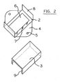
- FIG. 1 depicts the general housing appearance of one particular example of an automotive vehicle panic alarm system in accordance with an embodiment of the inventive disclosures made herein.
- the automotive vehicle panic alarm system enclosure assembly has a generally rectangular form. The major width and length dimensions are selected to accommodate a circuit board contained within, and in certain embodiments the cellular telephone compatible transceiver circuitry.
- the height of the enclosure assembly is selected to accommodate the mounted height of the circuit board and components in the enclosure including circuit board stand offs and component heights on the circuit board.
- the enclosure has a base which include one or more mounting tabs 4, each tab having one or more mounting holes 5, the holes provided to secure the panic alarm module under the dashboard, against the firewall or on any other desired mounting position on the automotive vehicle.
- Those skilled in the art will readily realize that other well-known enclosure configurations can be applied to enclose the panic alarm circuitry without deviating from the intention of this disclosure.
- the enclosure assembly 1 of this particular example of a simple first embodiment of an automotive vehicle panic alarm system comprises an enclosure base 2 and a U-formed removable housing cover 3.
- the housing cover is depicted as removed from the enclosure base for better understanding of the interior of the enclosure.
- an electronic circuit board 6 which is secured to the enclosure base 2 by a plurality of tubular mounting standoffs 7.
- a plurality of machine screws protruding through the circuit board into threads in the standoffs, and additional screws protruding through the enclosure based and into the opposing ends of the standoffs, such as to securely mount the circuit board to the enclosure base.
- the U-channel removable housing cover 3 is placed onto the enclosure base 2 by pressing the housing cover directly down over and in end to end alignment with the semi flexible end tabs 8.
- the end tabs are flexed slightly inwards towards the center of the enclosure during cover alignment and insertion.
- the end tabs are released to flex outwards and provide a thrust force against the bent retaining edges 9 of the cover 3.
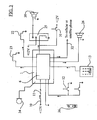
- FIG. 3 depicts a partial schematic, partial block diagram of devices interfaced to an embodiment of the vehicle panic alarm system in accordance with the inventive disclosures made herein.
- Circuit board 6 is provided in enclosure 1.
- Power supply wiring 10 runs from the vehicle electrical system to the circuit board 6, to provide power for the panic alarm system components.
- the +12VDC side of the wiring includes an inline bayonet or other form fuse 11 to protect the electrical system and the alarm components against a possible short circuit condition.
- the panic alarm circuit board includes an input 12 for one or more alarm activation switches or pushbuttons. As envisioned, a plurality of these pushbuttons may be electrically connected or wired in parallel (as shown).
- the alarm activation signal in this embodiment is active low, which is to say the alarm activation line is pulled to vehicle ground when an alarm activation pushbutton is depressed.
- the alarm activation push button or pushbuttons are envisioned to be momentary contact type.
- the alarm activation signal can alternately be generated by a human speaking the configured alarm activation phrase within the vicinity of a panic alarm pickup microphone 34.
- a Blue Tooth equipped mobile device such as a GSM cellular telephone having Blue Tooth capabilities can be used to remotely trigger an alarm activation signal to the panic alarm over a short distance, with a range of approximately 30 feet.
- the alarm condition is latched by the logic circuitry on the circuit board until the alarm is cancelled by the vehicle driver entering the proper numeric security pass code on the alarm cancellation keypad 13.
- the alarm can not be cancelled unless the proper security code is entered.
- the keypad may be mounted or hidden anywhere desired within the vehicle.
- the panic alarm circuit board provides several output, including vehicle +12VDC to the actuate and flash vehicle courtesy or marker lights 23, another output of +12VDC to drive and flash the vehicle headlights 22, a 12VDC lower current output intended to actuate and cycle the vehicle horn relay 25 on and off.
- Another +12VDC output is provided to continuously power an optional vehicle mounted siren.
- the siren may be mounted, for example, in the engine compartment where it is hidden from view. Additionally an output is provided for emergency services notification 32 to an integrated o separately interfaced cellular telephone device. This feature is discussed further below.
- the voltage potentials illustrated are for a negative ground, 12volt vehicle electrical system.
- FIG. 4 is block diagram of circuitry of an embodiment of the vehicle panic alarm system in accordance with the inventive disclosures made herein, illustrating by functional blocks the active components of one embodiment of the panic alarm system and connection to external devices.
- the active components of the panic alarm system include a processor and logic system 14, board mounted relays to drive external visual and audible alarm devices and semiconductor drivers which interface low level digital outputs from the processor and logic to the higher current levels required to drive the coils of the output relays.
- the panic alarm system includes a GPS (Global Positioning System) receiver 15, which provides vehicle global position coordinates to the processor and logic system.
- GPS Global Positioning System
- On-board non-volatile memory 16 provides storage for parameters including user selected alarm cancellation security numeric pass code, phone numbers the panic alarm system is to call in the event of an emergency (such as for police and security services), configured alarm activation phrase for alarms having voice alarm state activation cababilities, as well as other parameters.
- a MMC memory card or removable flash memory card is provided in certain embodiments, providing storage for periodically acquired CCD camera images of the driver seat, driver widow, passenger seat and rear vehicle areas, these images acquired and stored to removable flash memory card during an alarm condition.
- one to three CCD camera devices 39 are hidden within a vehicle rear view mirror assembly 38, the CCD camera's concealed behind a one way mirrored glass plate, the CCD cameras angled and positioned to capture images inside and outside the vehicle.
- a digital speech synthesizer 17 provides its output to either an integrated GSM cellular device 18, or to an external user provided cellular telephone, configuration depending on the embodiment chosen.
- the processor and logic system 14 dials emergency numbers previously configured by the owner in memory 16. Once the telephone at the called number answers, the processor and logic system sends an emergency voice message as well as the vehicle coordinates from the GPS system 15 to the speech synthesizer 17.
- the speech synthesizer 17 then feeds its synthesized human voice message to the called party. The message repeats for a pre-configured limited time, or until the person called hangs up.
- the processor and logic system selects the next configured phone number from memory, and repeats the above with this new number. This process continues, configured telephone number to number, call to call, until the alarm is deactivated.
- the processor and logic module generate outputs to the semiconductor driver components 20.
- the drivers provide higher current outputs to drive the relays 21.
- the relays provide higher current capacity interface points to drive the vehicles headlights 22, marker lights 23, panic alarm lights 24 , horn relay 25 and optionally the siren 26.
- the alarm is activated by a driver or occupant actuating one of the alarm activation switches, activating from a mobile device via Blue Tooth, or using a voice alarm activation, then all outputs are cycled on and off using a pseudo random sequence with the exception of the siren 26 which remains continuously on during the alarm.
- the alarm deactivates with the driver or another person enters the correct configured numeric security code into the alarm cancellation keypad.
- FIG. 5 is a flow chart of the events that occur when the panic alarm is activated.
- the alarm is activated when a driver or passenger actuates any of the alarm activation switches 50 mounted in the vehicle, or when the alarm is remotely activated via a wireless device such as a blue tooth equipped cellular phone, or when a person speaks the configured alarm activation phrase.
- the switches are envisioned as momentary contact pushbuttons, placed within convenient reach where desired inside the vehicle cockpit.
- the siren remains in a continuously on state until the alarm system is deactivated.
- a check is made if a cellular phone or GSM phone module is installed 53. If a cellular device is present and connected, the panic alarm system retrieves the vehicle location coordinates from the GPS system 54, if the alarm has a GPS receiver, and then dials the next configured phone number to be dialed 55 from the panic alarm memory. One of the configured numbers to be dialed would be the official national emergency call number, such as 911 in the United States.
- the emergency message is played 56, and the vehicle GPS coordinates are spoken 57 (if available) via the voice synthesizer into the cellular call connection. The message is repeated a predetermined number of times or until the party receiving the call hangs up 58.
- the alarm system advances to the next stored phone number 59 and if all numbers have been dialed repeats from the first phone number.
- the process repeats at 54 by obtaining the current vehicle GPS location, calling the next number, playing the emergency message and providing vehicle coordinates. This process loop continues until the panic alarm condition is cleared.
- the vehicle location may be obtained by the emergency call receiving authorities by use the features of a national cellular emergency call system, such and the Enhanced 911 system in the United States, or similar systems in other countries.
- the vehicle coordinates may be provided to authorities directly from the panic alarm automatically generated synthesized human voice message containing the vehicle location is global coordinates as decoded from the integrated GPS receiver
- FIG.6 is a flow chart of the events that occur when the driver enters a pass code to deactivate the panic alarm system.
- the driver or occupant enters the pass code 60 on the alarm system keypad. If the pass code is invalid 61 the code is discarded and the alarm system waits for the next pass code attempt. If the entered pass code is valid 61, the panic alarm system proceeds to deactivate the audio, visual alarm outputs 62. If the vehicle is equipped with an interfaced cellular phone device, the cellular auto dialing message loop (54-59) is aborted 63. The panic alarm system is now deactivated and returns to the non-alarm state 64.
- FIG. 7 is a front view of a vehicle equipped with an embodiment of the vehicle panic alarm system accordance with the inventive disclosures made herein, the illustrated vehicle including normal vehicle components such as headlights 22, tires 28, windshield 29.
- the front view illustrates the use of the optional panic alarm lights 27, in this case mounted beneath or near the grill.
- the panic alarm light are high intensity lights that will be cycled on and off during an alarm condition to draw attention to the attacker and help to thwart an attack.
Landscapes
- Engineering & Computer Science (AREA)
- Physics & Mathematics (AREA)
- General Physics & Mathematics (AREA)
- Mechanical Engineering (AREA)
- Emergency Management (AREA)
- Business, Economics & Management (AREA)
- Human Computer Interaction (AREA)
- Remote Sensing (AREA)
- Radar, Positioning & Navigation (AREA)
- Multimedia (AREA)
- Health & Medical Sciences (AREA)
- Audiology, Speech & Language Pathology (AREA)
- General Health & Medical Sciences (AREA)
- Computer Security & Cryptography (AREA)
- Alarm Systems (AREA)
Applications Claiming Priority (1)
| Application Number | Priority Date | Filing Date | Title |
|---|---|---|---|
| US63358404P | 2004-12-06 | 2004-12-06 |
Publications (1)
| Publication Number | Publication Date |
|---|---|
| EP1785964A1 true EP1785964A1 (fr) | 2007-05-16 |
Family
ID=35759317
Family Applications (1)
| Application Number | Title | Priority Date | Filing Date |
|---|---|---|---|
| EP05021481A Withdrawn EP1785964A1 (fr) | 2004-12-06 | 2005-09-30 | Système d'alarme anti-panique de véhicule automobile pour contrer une attaque, et son procédé |
Country Status (2)
| Country | Link |
|---|---|
| US (1) | US20060132294A1 (fr) |
| EP (1) | EP1785964A1 (fr) |
Cited By (1)
| Publication number | Priority date | Publication date | Assignee | Title |
|---|---|---|---|---|
| US11074769B2 (en) | 2019-03-26 | 2021-07-27 | Cambridge Mobile Telematics Inc. | Safety for vehicle users |
Families Citing this family (30)
| Publication number | Priority date | Publication date | Assignee | Title |
|---|---|---|---|---|
| CN100505796C (zh) * | 2004-11-24 | 2009-06-24 | 中兴通讯股份有限公司 | 一种手机显示时间的方法 |
| US7663504B2 (en) * | 2005-12-08 | 2010-02-16 | Sean Robert Votaw | Emergency vehicle warning system |
| US20100271480A1 (en) * | 2006-01-27 | 2010-10-28 | Leonid Bezborodko | Vehicular surveillance system |
| ITTV20070185A1 (it) * | 2007-11-19 | 2009-05-20 | New Tech Srl | Sistema di localizzazione satellitare con registrazione video/immagini per veicoli in genere. |
| US20090237507A1 (en) * | 2008-03-20 | 2009-09-24 | Milde Jr Karl F | Apparatus for logging motor vehicle speed and time |
| US20090273672A1 (en) * | 2008-05-01 | 2009-11-05 | Evgeni Koudritski | Vehicle recording system and method |
| US9659499B2 (en) * | 2008-12-22 | 2017-05-23 | General Motors Llc | Method of communicating vehicle messages using short message system messages |
| EP2648564A2 (fr) * | 2010-12-07 | 2013-10-16 | Csir | Transport d'objets de valeur |
| US9809196B1 (en) * | 2011-04-22 | 2017-11-07 | Emerging Automotive, Llc | Methods and systems for vehicle security and remote access and safety control interfaces and notifications |
| ITBO20120194A1 (it) * | 2012-04-12 | 2013-10-13 | Veronica Righini | Gruppo di sicurezza per impianti d'allarme prevalentemente per utilizzo in ambiente esterno. |
| KR20140023125A (ko) * | 2012-08-17 | 2014-02-26 | 엘지전자 주식회사 | 에너지 저장장치, 전력 관리 장치, 이동 단말기 및 그 동작방법 |
| US9168863B2 (en) * | 2012-12-03 | 2015-10-27 | Upfitters, L.L.C. | Flasher vehicle interface module |
| US9688246B2 (en) * | 2013-02-25 | 2017-06-27 | Ford Global Technologies, Llc | Method and apparatus for in-vehicle alarm activation and response handling |
| KR101286375B1 (ko) * | 2013-04-03 | 2013-07-15 | 정태승 | 차량의 패닉기능을 이용한 방범 시스템 |
| US9489966B1 (en) | 2015-05-29 | 2016-11-08 | Ford Global Technologies, Llc | Discreet emergency response |
| US9592795B1 (en) * | 2015-11-02 | 2017-03-14 | James A. Whiteside | Theft deterrence, prevention, and recovery system and method |
| WO2017155525A1 (fr) | 2016-03-09 | 2017-09-14 | Ford Global Technologies, Llc | Alerte de véhicule provenant d'un dispositif non apparié |
| US10586226B2 (en) | 2016-03-10 | 2020-03-10 | Ford Global Technologies, Llc | Integration of vehicle boundary alert system with external transaction equipment |
| US9779627B1 (en) * | 2016-03-31 | 2017-10-03 | Cae Inc. | Method, device and system for calculating weighted deployment rules in an emergency-vehicle-units deployment system for a geographical area |
| DE102016009580A1 (de) * | 2016-08-04 | 2018-02-08 | Franz Hargasser | Verfahren zur Übermittlung von Bildern einer Kamera an eine Zieladresse |
| US20180118160A1 (en) * | 2016-10-28 | 2018-05-03 | Panasonic Automotive Systems Company Of America, Division Of Panasonic Corporation Of North America | Single button activation of all vehicle security functions |
| EP3549114A1 (fr) * | 2016-12-05 | 2019-10-09 | Signify Holding B.V. | Objet de détection de vol |
| US10181253B2 (en) * | 2016-12-28 | 2019-01-15 | On View Security | System and method for emergency situation broadcasting and location detection |
| DE102017201424A1 (de) | 2017-01-30 | 2018-08-02 | Bayerische Motoren Werke Aktiengesellschaft | Verfahren zum Betreiben eines Kraftfahrzeugs und Kraftfahrzeugsystem |
| WO2018143980A1 (fr) * | 2017-02-01 | 2018-08-09 | Whiteside James A | Système et procédé de dissuasion, de prévention et de récupération de vol |
| US10787151B2 (en) * | 2018-03-20 | 2020-09-29 | The Boeing Company | Local access indication system |
| CN108454568A (zh) * | 2018-03-27 | 2018-08-28 | 浙江鼎奕科技发展有限公司 | 车辆安全监控方法及系统 |
| US10793106B2 (en) * | 2018-11-05 | 2020-10-06 | Robert Turley | Automobile tracking and notification device and service |
| CN109733327B (zh) * | 2019-02-14 | 2020-04-14 | 成都路行通信息技术有限公司 | 一种智能定位器被拆除预警方法 |
| WO2020242466A1 (fr) * | 2019-05-29 | 2020-12-03 | Owl Cameras, Inc. | Génération et rapport d'événement de haute priorité pour système de sécurité basé sur une caméra |
Citations (6)
| Publication number | Priority date | Publication date | Assignee | Title |
|---|---|---|---|---|
| EP0915443A2 (fr) * | 1997-11-06 | 1999-05-12 | GRUNDIG Aktiengesellschaft | Dispositif d'appel d'urgence dans une voiture |
| US6147598A (en) * | 1997-07-03 | 2000-11-14 | Trimble Navigation Limited | Vehicle theft system including a handheld computing device |
| US20020070879A1 (en) * | 2000-12-12 | 2002-06-13 | Gazit Hanoch Amatzia | "On-board" vehicle safety system |
| US20020101336A1 (en) * | 1999-01-05 | 2002-08-01 | Code Alarm, Inc. | Vehicle security system |
| US6675006B1 (en) * | 2000-05-26 | 2004-01-06 | Alpine Electronics, Inc. | Vehicle-mounted system |
| GB2395830A (en) * | 2002-04-15 | 2004-06-02 | Michael Cole | Universal mobile alarm dialler |
Family Cites Families (6)
| Publication number | Priority date | Publication date | Assignee | Title |
|---|---|---|---|---|
| US4143368A (en) * | 1977-12-05 | 1979-03-06 | General Motors Corporation | Vehicle operator security system |
| US4691801A (en) * | 1986-03-03 | 1987-09-08 | Yale Mann | Vehicle protection device |
| IT1201858B (it) * | 1986-12-03 | 1989-02-02 | Delta Elettronica Spa | Impianto antifurto |
| US5555286A (en) * | 1994-01-31 | 1996-09-10 | Tendler Technologies, Inc. | Cellular phone based automatic emergency vessel/vehicle location system |
| US6150923A (en) * | 1996-10-10 | 2000-11-21 | Johnson; William Nevil Heaton | Alarm system |
| US6181238B1 (en) * | 1997-03-11 | 2001-01-30 | Charles N. Garrett, Sr. | Panic button alarm actuator |
-
2005
- 2005-09-30 EP EP05021481A patent/EP1785964A1/fr not_active Withdrawn
- 2005-12-06 US US11/294,829 patent/US20060132294A1/en not_active Abandoned
Patent Citations (6)
| Publication number | Priority date | Publication date | Assignee | Title |
|---|---|---|---|---|
| US6147598A (en) * | 1997-07-03 | 2000-11-14 | Trimble Navigation Limited | Vehicle theft system including a handheld computing device |
| EP0915443A2 (fr) * | 1997-11-06 | 1999-05-12 | GRUNDIG Aktiengesellschaft | Dispositif d'appel d'urgence dans une voiture |
| US20020101336A1 (en) * | 1999-01-05 | 2002-08-01 | Code Alarm, Inc. | Vehicle security system |
| US6675006B1 (en) * | 2000-05-26 | 2004-01-06 | Alpine Electronics, Inc. | Vehicle-mounted system |
| US20020070879A1 (en) * | 2000-12-12 | 2002-06-13 | Gazit Hanoch Amatzia | "On-board" vehicle safety system |
| GB2395830A (en) * | 2002-04-15 | 2004-06-02 | Michael Cole | Universal mobile alarm dialler |
Cited By (2)
| Publication number | Priority date | Publication date | Assignee | Title |
|---|---|---|---|---|
| US11074769B2 (en) | 2019-03-26 | 2021-07-27 | Cambridge Mobile Telematics Inc. | Safety for vehicle users |
| US11210873B2 (en) | 2019-03-26 | 2021-12-28 | Cambridge Mobile Telematics Inc. | Safety for vehicle users |
Also Published As
| Publication number | Publication date |
|---|---|
| US20060132294A1 (en) | 2006-06-22 |
Similar Documents
| Publication | Publication Date | Title |
|---|---|---|
| EP1785964A1 (fr) | Système d'alarme anti-panique de véhicule automobile pour contrer une attaque, et son procédé | |
| US5918180A (en) | Telephone operable global tracking system for vehicles | |
| US5555286A (en) | Cellular phone based automatic emergency vessel/vehicle location system | |
| US7468667B2 (en) | Anti-thief owner notification alarm system for a two-wheeled vehicle, and method of same | |
| US7590405B2 (en) | Apparatus for enabling a mobile communicator and methods of using the same | |
| US20180072263A1 (en) | Vehicle-disabling remote anti-theft system and method | |
| CA2519754C (fr) | Robot protecteur intelligent automatise pour voitures et transports | |
| US20050151628A1 (en) | Method and system for accessing and viewing images of a vehicle interior | |
| US6717511B2 (en) | Vehicle alarm and theft deterrent system | |
| EP1698158A1 (fr) | Systeme de conference telephonique d urgence | |
| US20030227381A1 (en) | Alarm notification device | |
| US20110128346A1 (en) | System of deploying videophone and early warning | |
| GB2372612A (en) | Mobile phone combined with a detector for remote signalling of a sensed condition | |
| GB2402530A (en) | Vehicle security system with interior images sent to remote location via cellular telephone | |
| CN101445095B (zh) | 联网汽车防盗报警方法及其报警系统 | |
| JP2002304686A5 (fr) | ||
| WO2002035488A2 (fr) | Systeme de surveillance et d'alerte anti-vol/anti-effraction fonde sur un dispositif de communication cellulaire | |
| WO2016153444A1 (fr) | Procédé de contact de propriétaires de véhicules mal garés et système de mise en œuvre dudit procédé | |
| JP2005029138A (ja) | 自動車盗難防止システム | |
| CN1719482B (zh) | 能迫使预谋犯罪的人放弃作案念头的车载系统及使用方法 | |
| CN1672396A (zh) | 移动电话设备 | |
| JP2003242578A (ja) | 盗難防止用マイカー監視システム | |
| JP2001338378A (ja) | 室内異常通報装置および車両用室内侵入通知および撮影記録装置 | |
| CN2695305Y (zh) | 机动车辆防盗抢定位追踪装置 | |
| KR20040031836A (ko) | 자동차용 화상 안전 시스템 |
Legal Events
| Date | Code | Title | Description |
|---|---|---|---|
| PUAI | Public reference made under article 153(3) epc to a published international application that has entered the european phase |
Free format text: ORIGINAL CODE: 0009012 |
|
| AK | Designated contracting states |
Kind code of ref document: A1 Designated state(s): AT BE BG CH CY CZ DE DK EE ES FI FR GB GR HU IE IS IT LI LT LU LV MC NL PL PT RO SE SI SK TR |
|
| AX | Request for extension of the european patent |
Extension state: AL BA HR MK YU |
|
| AKX | Designation fees paid |
Designated state(s): AT BE BG CH CY CZ DE DK EE ES FI FR GB GR HU IE IS IT LI LT LU LV MC NL PL PT RO SE SI SK TR |
|
| STAA | Information on the status of an ep patent application or granted ep patent |
Free format text: STATUS: THE APPLICATION IS DEEMED TO BE WITHDRAWN |
|
| 18D | Application deemed to be withdrawn |
Effective date: 20071117 |