WO2012036086A1 - Groupe d'unités de stockage de charge, chargeur, dispositif électronique, véhicule entraîné électriquement, procédé de chargement et procédé de déchargement d'un groupe d'unités de stockage de charge, procédé d'amenée/de réception de courant électrique, et procédé de détermination d'un itinéraire de charge/de décharge dans le groupe d'unités de stockage de charge - Google Patents
Groupe d'unités de stockage de charge, chargeur, dispositif électronique, véhicule entraîné électriquement, procédé de chargement et procédé de déchargement d'un groupe d'unités de stockage de charge, procédé d'amenée/de réception de courant électrique, et procédé de détermination d'un itinéraire de charge/de décharge dans le groupe d'unités de stockage de charge Download PDFInfo
- Publication number
- WO2012036086A1 WO2012036086A1 PCT/JP2011/070615 JP2011070615W WO2012036086A1 WO 2012036086 A1 WO2012036086 A1 WO 2012036086A1 JP 2011070615 W JP2011070615 W JP 2011070615W WO 2012036086 A1 WO2012036086 A1 WO 2012036086A1
- Authority
- WO
- WIPO (PCT)
- Prior art keywords
- storage unit
- power storage
- power
- charging
- secondary battery
- Prior art date
Links
Images


Classifications
-
- B—PERFORMING OPERATIONS; TRANSPORTING
- B60—VEHICLES IN GENERAL
- B60L—PROPULSION OF ELECTRICALLY-PROPELLED VEHICLES; SUPPLYING ELECTRIC POWER FOR AUXILIARY EQUIPMENT OF ELECTRICALLY-PROPELLED VEHICLES; ELECTRODYNAMIC BRAKE SYSTEMS FOR VEHICLES IN GENERAL; MAGNETIC SUSPENSION OR LEVITATION FOR VEHICLES; MONITORING OPERATING VARIABLES OF ELECTRICALLY-PROPELLED VEHICLES; ELECTRIC SAFETY DEVICES FOR ELECTRICALLY-PROPELLED VEHICLES
- B60L53/00—Methods of charging batteries, specially adapted for electric vehicles; Charging stations or on-board charging equipment therefor; Exchange of energy storage elements in electric vehicles
-
- B—PERFORMING OPERATIONS; TRANSPORTING
- B60—VEHICLES IN GENERAL
- B60L—PROPULSION OF ELECTRICALLY-PROPELLED VEHICLES; SUPPLYING ELECTRIC POWER FOR AUXILIARY EQUIPMENT OF ELECTRICALLY-PROPELLED VEHICLES; ELECTRODYNAMIC BRAKE SYSTEMS FOR VEHICLES IN GENERAL; MAGNETIC SUSPENSION OR LEVITATION FOR VEHICLES; MONITORING OPERATING VARIABLES OF ELECTRICALLY-PROPELLED VEHICLES; ELECTRIC SAFETY DEVICES FOR ELECTRICALLY-PROPELLED VEHICLES
- B60L50/00—Electric propulsion with power supplied within the vehicle
- B60L50/50—Electric propulsion with power supplied within the vehicle using propulsion power supplied by batteries or fuel cells
- B60L50/60—Electric propulsion with power supplied within the vehicle using propulsion power supplied by batteries or fuel cells using power supplied by batteries
- B60L50/66—Arrangements of batteries
-
- B—PERFORMING OPERATIONS; TRANSPORTING
- B60—VEHICLES IN GENERAL
- B60L—PROPULSION OF ELECTRICALLY-PROPELLED VEHICLES; SUPPLYING ELECTRIC POWER FOR AUXILIARY EQUIPMENT OF ELECTRICALLY-PROPELLED VEHICLES; ELECTRODYNAMIC BRAKE SYSTEMS FOR VEHICLES IN GENERAL; MAGNETIC SUSPENSION OR LEVITATION FOR VEHICLES; MONITORING OPERATING VARIABLES OF ELECTRICALLY-PROPELLED VEHICLES; ELECTRIC SAFETY DEVICES FOR ELECTRICALLY-PROPELLED VEHICLES
- B60L53/00—Methods of charging batteries, specially adapted for electric vehicles; Charging stations or on-board charging equipment therefor; Exchange of energy storage elements in electric vehicles
- B60L53/50—Charging stations characterised by energy-storage or power-generation means
- B60L53/51—Photovoltaic means
-
- B—PERFORMING OPERATIONS; TRANSPORTING
- B60—VEHICLES IN GENERAL
- B60L—PROPULSION OF ELECTRICALLY-PROPELLED VEHICLES; SUPPLYING ELECTRIC POWER FOR AUXILIARY EQUIPMENT OF ELECTRICALLY-PROPELLED VEHICLES; ELECTRODYNAMIC BRAKE SYSTEMS FOR VEHICLES IN GENERAL; MAGNETIC SUSPENSION OR LEVITATION FOR VEHICLES; MONITORING OPERATING VARIABLES OF ELECTRICALLY-PROPELLED VEHICLES; ELECTRIC SAFETY DEVICES FOR ELECTRICALLY-PROPELLED VEHICLES
- B60L53/00—Methods of charging batteries, specially adapted for electric vehicles; Charging stations or on-board charging equipment therefor; Exchange of energy storage elements in electric vehicles
- B60L53/50—Charging stations characterised by energy-storage or power-generation means
- B60L53/52—Wind-driven generators
-
- B—PERFORMING OPERATIONS; TRANSPORTING
- B60—VEHICLES IN GENERAL
- B60L—PROPULSION OF ELECTRICALLY-PROPELLED VEHICLES; SUPPLYING ELECTRIC POWER FOR AUXILIARY EQUIPMENT OF ELECTRICALLY-PROPELLED VEHICLES; ELECTRODYNAMIC BRAKE SYSTEMS FOR VEHICLES IN GENERAL; MAGNETIC SUSPENSION OR LEVITATION FOR VEHICLES; MONITORING OPERATING VARIABLES OF ELECTRICALLY-PROPELLED VEHICLES; ELECTRIC SAFETY DEVICES FOR ELECTRICALLY-PROPELLED VEHICLES
- B60L53/00—Methods of charging batteries, specially adapted for electric vehicles; Charging stations or on-board charging equipment therefor; Exchange of energy storage elements in electric vehicles
- B60L53/50—Charging stations characterised by energy-storage or power-generation means
- B60L53/53—Batteries
-
- B—PERFORMING OPERATIONS; TRANSPORTING
- B60—VEHICLES IN GENERAL
- B60L—PROPULSION OF ELECTRICALLY-PROPELLED VEHICLES; SUPPLYING ELECTRIC POWER FOR AUXILIARY EQUIPMENT OF ELECTRICALLY-PROPELLED VEHICLES; ELECTRODYNAMIC BRAKE SYSTEMS FOR VEHICLES IN GENERAL; MAGNETIC SUSPENSION OR LEVITATION FOR VEHICLES; MONITORING OPERATING VARIABLES OF ELECTRICALLY-PROPELLED VEHICLES; ELECTRIC SAFETY DEVICES FOR ELECTRICALLY-PROPELLED VEHICLES
- B60L53/00—Methods of charging batteries, specially adapted for electric vehicles; Charging stations or on-board charging equipment therefor; Exchange of energy storage elements in electric vehicles
- B60L53/50—Charging stations characterised by energy-storage or power-generation means
- B60L53/54—Fuel cells
-
- B—PERFORMING OPERATIONS; TRANSPORTING
- B60—VEHICLES IN GENERAL
- B60L—PROPULSION OF ELECTRICALLY-PROPELLED VEHICLES; SUPPLYING ELECTRIC POWER FOR AUXILIARY EQUIPMENT OF ELECTRICALLY-PROPELLED VEHICLES; ELECTRODYNAMIC BRAKE SYSTEMS FOR VEHICLES IN GENERAL; MAGNETIC SUSPENSION OR LEVITATION FOR VEHICLES; MONITORING OPERATING VARIABLES OF ELECTRICALLY-PROPELLED VEHICLES; ELECTRIC SAFETY DEVICES FOR ELECTRICALLY-PROPELLED VEHICLES
- B60L58/00—Methods or circuit arrangements for monitoring or controlling batteries or fuel cells, specially adapted for electric vehicles
- B60L58/10—Methods or circuit arrangements for monitoring or controlling batteries or fuel cells, specially adapted for electric vehicles for monitoring or controlling batteries
- B60L58/18—Methods or circuit arrangements for monitoring or controlling batteries or fuel cells, specially adapted for electric vehicles for monitoring or controlling batteries of two or more battery modules
-
- H—ELECTRICITY
- H01—ELECTRIC ELEMENTS
- H01M—PROCESSES OR MEANS, e.g. BATTERIES, FOR THE DIRECT CONVERSION OF CHEMICAL ENERGY INTO ELECTRICAL ENERGY
- H01M10/00—Secondary cells; Manufacture thereof
- H01M10/42—Methods or arrangements for servicing or maintenance of secondary cells or secondary half-cells
- H01M10/44—Methods for charging or discharging
- H01M10/441—Methods for charging or discharging for several batteries or cells simultaneously or sequentially
-
- H—ELECTRICITY
- H02—GENERATION; CONVERSION OR DISTRIBUTION OF ELECTRIC POWER
- H02J—CIRCUIT ARRANGEMENTS OR SYSTEMS FOR SUPPLYING OR DISTRIBUTING ELECTRIC POWER; SYSTEMS FOR STORING ELECTRIC ENERGY
- H02J7/00—Circuit arrangements for charging or depolarising batteries or for supplying loads from batteries
- H02J7/0013—Circuit arrangements for charging or depolarising batteries or for supplying loads from batteries acting upon several batteries simultaneously or sequentially
- H02J7/0014—Circuits for equalisation of charge between batteries
- H02J7/0016—Circuits for equalisation of charge between batteries using shunting, discharge or bypass circuits
-
- H—ELECTRICITY
- H02—GENERATION; CONVERSION OR DISTRIBUTION OF ELECTRIC POWER
- H02J—CIRCUIT ARRANGEMENTS OR SYSTEMS FOR SUPPLYING OR DISTRIBUTING ELECTRIC POWER; SYSTEMS FOR STORING ELECTRIC ENERGY
- H02J7/00—Circuit arrangements for charging or depolarising batteries or for supplying loads from batteries
- H02J7/0013—Circuit arrangements for charging or depolarising batteries or for supplying loads from batteries acting upon several batteries simultaneously or sequentially
- H02J7/0014—Circuits for equalisation of charge between batteries
- H02J7/0019—Circuits for equalisation of charge between batteries using switched or multiplexed charge circuits
-
- H—ELECTRICITY
- H02—GENERATION; CONVERSION OR DISTRIBUTION OF ELECTRIC POWER
- H02J—CIRCUIT ARRANGEMENTS OR SYSTEMS FOR SUPPLYING OR DISTRIBUTING ELECTRIC POWER; SYSTEMS FOR STORING ELECTRIC ENERGY
- H02J7/00—Circuit arrangements for charging or depolarising batteries or for supplying loads from batteries
- H02J7/0013—Circuit arrangements for charging or depolarising batteries or for supplying loads from batteries acting upon several batteries simultaneously or sequentially
- H02J7/0025—Sequential battery discharge in systems with a plurality of batteries
-
- H—ELECTRICITY
- H01—ELECTRIC ELEMENTS
- H01M—PROCESSES OR MEANS, e.g. BATTERIES, FOR THE DIRECT CONVERSION OF CHEMICAL ENERGY INTO ELECTRICAL ENERGY
- H01M6/00—Primary cells; Manufacture thereof
- H01M6/42—Grouping of primary cells into batteries
-
- H—ELECTRICITY
- H02—GENERATION; CONVERSION OR DISTRIBUTION OF ELECTRIC POWER
- H02J—CIRCUIT ARRANGEMENTS OR SYSTEMS FOR SUPPLYING OR DISTRIBUTING ELECTRIC POWER; SYSTEMS FOR STORING ELECTRIC ENERGY
- H02J2207/00—Indexing scheme relating to details of circuit arrangements for charging or depolarising batteries or for supplying loads from batteries
- H02J2207/20—Charging or discharging characterised by the power electronics converter
-
- H—ELECTRICITY
- H02—GENERATION; CONVERSION OR DISTRIBUTION OF ELECTRIC POWER
- H02J—CIRCUIT ARRANGEMENTS OR SYSTEMS FOR SUPPLYING OR DISTRIBUTING ELECTRIC POWER; SYSTEMS FOR STORING ELECTRIC ENERGY
- H02J7/00—Circuit arrangements for charging or depolarising batteries or for supplying loads from batteries
- H02J7/0042—Circuit arrangements for charging or depolarising batteries or for supplying loads from batteries characterised by the mechanical construction
-
- Y—GENERAL TAGGING OF NEW TECHNOLOGICAL DEVELOPMENTS; GENERAL TAGGING OF CROSS-SECTIONAL TECHNOLOGIES SPANNING OVER SEVERAL SECTIONS OF THE IPC; TECHNICAL SUBJECTS COVERED BY FORMER USPC CROSS-REFERENCE ART COLLECTIONS [XRACs] AND DIGESTS
- Y02—TECHNOLOGIES OR APPLICATIONS FOR MITIGATION OR ADAPTATION AGAINST CLIMATE CHANGE
- Y02E—REDUCTION OF GREENHOUSE GAS [GHG] EMISSIONS, RELATED TO ENERGY GENERATION, TRANSMISSION OR DISTRIBUTION
- Y02E60/00—Enabling technologies; Technologies with a potential or indirect contribution to GHG emissions mitigation
- Y02E60/10—Energy storage using batteries
-
- Y—GENERAL TAGGING OF NEW TECHNOLOGICAL DEVELOPMENTS; GENERAL TAGGING OF CROSS-SECTIONAL TECHNOLOGIES SPANNING OVER SEVERAL SECTIONS OF THE IPC; TECHNICAL SUBJECTS COVERED BY FORMER USPC CROSS-REFERENCE ART COLLECTIONS [XRACs] AND DIGESTS
- Y02—TECHNOLOGIES OR APPLICATIONS FOR MITIGATION OR ADAPTATION AGAINST CLIMATE CHANGE
- Y02T—CLIMATE CHANGE MITIGATION TECHNOLOGIES RELATED TO TRANSPORTATION
- Y02T10/00—Road transport of goods or passengers
- Y02T10/60—Other road transportation technologies with climate change mitigation effect
- Y02T10/70—Energy storage systems for electromobility, e.g. batteries
-
- Y—GENERAL TAGGING OF NEW TECHNOLOGICAL DEVELOPMENTS; GENERAL TAGGING OF CROSS-SECTIONAL TECHNOLOGIES SPANNING OVER SEVERAL SECTIONS OF THE IPC; TECHNICAL SUBJECTS COVERED BY FORMER USPC CROSS-REFERENCE ART COLLECTIONS [XRACs] AND DIGESTS
- Y02—TECHNOLOGIES OR APPLICATIONS FOR MITIGATION OR ADAPTATION AGAINST CLIMATE CHANGE
- Y02T—CLIMATE CHANGE MITIGATION TECHNOLOGIES RELATED TO TRANSPORTATION
- Y02T10/00—Road transport of goods or passengers
- Y02T10/60—Other road transportation technologies with climate change mitigation effect
- Y02T10/7072—Electromobility specific charging systems or methods for batteries, ultracapacitors, supercapacitors or double-layer capacitors
-
- Y—GENERAL TAGGING OF NEW TECHNOLOGICAL DEVELOPMENTS; GENERAL TAGGING OF CROSS-SECTIONAL TECHNOLOGIES SPANNING OVER SEVERAL SECTIONS OF THE IPC; TECHNICAL SUBJECTS COVERED BY FORMER USPC CROSS-REFERENCE ART COLLECTIONS [XRACs] AND DIGESTS
- Y02—TECHNOLOGIES OR APPLICATIONS FOR MITIGATION OR ADAPTATION AGAINST CLIMATE CHANGE
- Y02T—CLIMATE CHANGE MITIGATION TECHNOLOGIES RELATED TO TRANSPORTATION
- Y02T90/00—Enabling technologies or technologies with a potential or indirect contribution to GHG emissions mitigation
- Y02T90/10—Technologies relating to charging of electric vehicles
- Y02T90/12—Electric charging stations
-
- Y—GENERAL TAGGING OF NEW TECHNOLOGICAL DEVELOPMENTS; GENERAL TAGGING OF CROSS-SECTIONAL TECHNOLOGIES SPANNING OVER SEVERAL SECTIONS OF THE IPC; TECHNICAL SUBJECTS COVERED BY FORMER USPC CROSS-REFERENCE ART COLLECTIONS [XRACs] AND DIGESTS
- Y02—TECHNOLOGIES OR APPLICATIONS FOR MITIGATION OR ADAPTATION AGAINST CLIMATE CHANGE
- Y02T—CLIMATE CHANGE MITIGATION TECHNOLOGIES RELATED TO TRANSPORTATION
- Y02T90/00—Enabling technologies or technologies with a potential or indirect contribution to GHG emissions mitigation
- Y02T90/10—Technologies relating to charging of electric vehicles
- Y02T90/14—Plug-in electric vehicles
Definitions
- the present disclosure relates to a storage unit group, a charger, an electronic device, an electric vehicle, a charging method and a discharging method for the storage unit group, a power supply / reception method, and a charging / discharging route determination method in the storage unit group.
- a battery pack (assembled battery) comprising a plurality of secondary batteries (single cells) connected in parallel and a plurality of secondary batteries connected in parallel connected in series ), And such a battery pack is known from, for example, Japanese Patent Laid-Open No. 6-283210. Normally, in such a battery pack, power for charging is supplied from one end of the battery pack, and a load is connected to the battery pack to supply power to the load.
- an object of the present disclosure is to provide a power storage unit group including a plurality of battery packs (power storage units) connected in a desired form, a charger including the power storage unit group, an electronic device, an electric vehicle, and a power storage unit group.
- An object of the present invention is to provide a charging method and a discharging method, a power supply / reception method, and a charging / discharging route determination method in a power storage unit group.
- the power storage unit group according to the first aspect of the present disclosure for achieving the above object is a power storage unit group in which a plurality of power storage units each having a secondary battery cell are connected in a linear or mesh shape. , Connected to a power source for charging the storage unit upstream of the storage unit group, If the secondary battery cell constituting one power storage unit is fully charged, charging of the one power storage unit is stopped, and the downstream side of the one power storage unit via the one power storage unit The power storage unit connected to is charged.
- the power storage unit group according to the second aspect of the present disclosure for achieving the above object is a power storage unit group in which a plurality of power storage units each having a secondary battery cell are connected in a straight line or a network. , Connected to the load on the downstream side of the storage unit group, When the voltage of the secondary battery cell constituting one power storage unit becomes a predetermined voltage or less, the discharge from the one power storage unit is stopped, and the power storage unit connected to the upstream side of the one power storage unit Is started to discharge.
- the charger according to the first aspect of the present disclosure for achieving the above object is configured of a power storage unit group in which a plurality of power storage units each having a secondary battery cell are connected in a linear or mesh shape.
- a charger The storage unit group is connected to a power source for charging the storage unit on the upstream side of the storage unit group, If the secondary battery cell constituting one power storage unit is fully charged, charging of the one power storage unit is stopped, and the downstream side of the one power storage unit via the one power storage unit The power storage unit connected to is charged.
- the charger according to the second aspect of the present disclosure for achieving the above object is configured of a power storage unit group in which a plurality of power storage units each having a secondary battery cell are connected in a linear or mesh shape.
- a charger, The storage unit group is connected to a load on the downstream side of the storage unit group, When the voltage of the secondary battery cell constituting one power storage unit becomes a predetermined voltage or less, the discharge from the one power storage unit is stopped, and the power storage unit connected to the upstream side of the one power storage unit Is started to discharge.
- the electronic device for achieving the above-described object is: A plurality of power storage units having secondary battery cells, a plurality of power storage units connected in a straight line or a network, and Electronic components that are supplied with power from the storage unit group, An electronic device having The power storage unit group is connected to the power source for charging the power storage unit on the upstream side of the power storage unit group, and connected to the electronic component on the downstream side of the power storage unit group, If the secondary battery cell constituting one power storage unit is fully charged, charging of the one power storage unit is stopped, and the downstream side of the one power storage unit via the one power storage unit The power storage unit connected to is charged.
- An electronic device for achieving the above object is as follows: A plurality of power storage units having secondary battery cells, a plurality of power storage units connected in a straight line or a network, and Electronic components that are supplied with power from the storage unit group, An electronic device having The power storage unit group is connected to the electronic component on the downstream side of the power storage unit group, When the voltage of the secondary battery cell constituting one power storage unit becomes a predetermined voltage or less, the discharge from the one power storage unit is stopped, and the power storage unit connected to the upstream side of the one power storage unit Is started to discharge.
- the electric vehicle according to the first aspect of the present disclosure for achieving the above object is A plurality of power storage units having secondary battery cells, a plurality of power storage units connected in a straight line or a network, Power generator, and Power driving force converter,
- An electric vehicle comprising: The power storage unit group is connected to a power generation device for charging the power storage unit on the upstream side of the power storage unit group, and is connected to the power driving force conversion device on the downstream side of the power storage unit group, If the secondary battery cell constituting one power storage unit is fully charged, charging of the one power storage unit is stopped, and the downstream side of the one power storage unit via the one power storage unit The power storage unit connected to is charged.
- An electric vehicle for achieving the above object is A plurality of power storage units having secondary battery cells, a plurality of power storage units connected in a straight line or a network, Power generator, and Power driving force converter,
- An electric vehicle comprising: The power storage unit group is connected to a power generation device for charging the power storage unit on the upstream side of the power storage unit group, and is connected to the power driving force conversion device on the downstream side of the power storage unit group, When the voltage of the secondary battery cell constituting one power storage unit becomes a predetermined voltage or less, the discharge from the one power storage unit is stopped, and the power storage unit connected to the upstream side of the one power storage unit Is started to discharge.
- a method for charging a power storage unit group provides a method for charging a secondary battery cell in a power storage unit group in which a plurality of power storage units each having a secondary battery cell are connected in a straight line or a network. Charging method, The storage unit group is connected to a power source for charging the storage unit on the upstream side of the storage unit group, When the secondary battery cell constituting one power storage unit is fully charged, the charging of the one power storage unit is stopped, and the downstream side of the one power storage unit via the one power storage unit A charging step of charging the power storage unit connected to the.
- a method for discharging a power storage unit group provides a method for discharging secondary battery cells in a power storage unit group in which a plurality of power storage units having secondary battery cells are connected in a straight line or a network.
- a discharge method The storage unit group is connected to a load on the downstream side of the storage unit group, When the voltage of the secondary battery cell constituting one power storage unit becomes a predetermined voltage or lower, the discharge from the one power storage unit is stopped, and the power storage unit connected to the upstream side of the one power storage unit A discharge step for starting the discharge.
- the power supply / reception method for achieving the above object is as follows: A power storage unit having secondary battery cells supplies power from a plurality of power storage unit groups connected in a straight line or a network, A power supply / reception method for receiving power from a power generation device and a power grid (including a smart grid and a next-generation power grid), The storage unit group is connected to a power generation device for charging the storage unit on the upstream side of the storage unit group via a power transmission network, and connected to a load on the downstream side of the storage unit group.
- the secondary battery cell constituting one power storage unit is fully charged, the charging of the one power storage unit is stopped, and the downstream side of the one power storage unit via the one power storage unit A charging step of charging the power storage unit connected to the.
- a power storage unit having secondary battery cells supplies power from a plurality of power storage unit groups connected in a straight line or a network
- the storage unit group is connected to a power generation device for charging the storage unit on the upstream side of the storage unit group via a power transmission network, and connected to a load on the downstream side of the storage unit group.
- the charge / discharge route determination method in the power storage unit group of the present disclosure for achieving the above-described object is A plurality of power storage units each having a secondary battery cell are connected to each other in a linear or mesh shape, Connected to a power source for charging the storage unit upstream of the storage unit group, A charging / discharging route determination method in a power storage unit group connected to a load on the downstream side of the power storage unit group,
- N an Nth-order square matrix A is obtained
- the value of the element [i, j] (where 1 ⁇ i ⁇ N, 1 ⁇ j ⁇ N) of the N-order square matrix A is “0” means that the i-th storage unit and the j-th Represents that the power storage unit is not connected
- the value of the element [i, j] of the N-th square matrix A is “1” means that the i th power storage unit and the j th power storage unit And are connected
- the k m ′ + 1 th power storage unit immediately before the k m ′ th power storage unit in the power storage unit existing from the i th power storage unit to the km m ′ th power storage unit Designate the power storage unit and repeat this operation until the value of m ′ changes from 1 to (m ⁇ 1), and specify the power storage unit that exists from the i-th power storage unit to the j-th power storage unit. In addition, the operation is performed for all the power storage units, from the i-th power storage unit to the j-th power storage unit. Determine the charge / discharge route.
- the voltage of the secondary battery cell constituting one power storage unit becomes a predetermined voltage or less. If this is the case, the electric storage unit including the secondary battery cell is provided with a discharging step of stopping discharging from the one electric storage unit and starting discharging the electric storage unit connected to the upstream side of the one electric storage unit. In addition, it is possible to reliably discharge the power storage units in the power storage unit group that is connected in a plurality of lines or in a mesh shape, and a discharge loop occurs in the discharge route in the power storage unit group during the discharge of the power storage unit.
- the clustered power storage units can be used safely and efficiently, and can be used according to one type of specifications such as use at a place where the charging method is executed and use at other places. It becomes possible to use without being limited.
- the charger, the electronic device, or the electric vehicle if the secondary battery cell configuring one power storage unit is fully charged, the one power storage The charging of the unit is stopped, and the power storage unit connected to the downstream side of the one power storage unit is charged via the one power storage unit. Therefore, not only can the power storage unit be reliably charged, but also charging of the power storage unit can be reliably prevented from generating a charging loop in the charging route in the power storage unit group. Charging, it is possible to set the optimal charging route.
- the charger, the electronic device or the electric vehicle according to the second aspect of the present disclosure, if the voltage of the secondary battery cell constituting one power storage unit is equal to or lower than a predetermined voltage, Discharging from the one power storage unit is stopped, and discharging of the power storage unit connected to the upstream side of the one power storage unit is started. Therefore, it is possible to reliably discharge the power storage unit, and it is possible to reliably prevent a discharge loop from occurring in the discharge route in the power storage unit group during the discharge of the power storage unit. It is possible to set an optimal discharge route.
- the clustered power storage units can be used safely and efficiently, and can be used according to one type of specifications such as use at a place where the charging method is executed and use at other places. It becomes possible to use without being limited.
- the charging / discharging route determination method in the power storage unit group according to the present disclosure can surely determine the shortest charging / discharging route in the power storage unit group in spite of being a simple method.
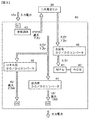
- FIG. 1A and 1B are schematic views of a power storage unit group in which six power storage units according to the present disclosure are combined and viewed from above.
- FIG. 1A is a power storage unit according to the first embodiment.
- FIG. 1B is a diagram illustrating a power path in the charging method for the power storage unit group according to the second embodiment.
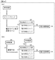
- (A), (B), and (C) of FIG. 2 are each a schematic perspective view of a power storage unit group in which three power storage units in the present disclosure are combined, a schematic view of the power storage unit group as viewed from above, And it is a schematic diagram when the inside of an electrical storage unit is seen.
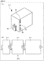
- FIG. 3 is a block diagram of charge / discharge control means for the secondary battery cell and the power storage unit in the present disclosure.
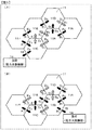
- FIGS. 5A and 5B are diagrams illustrating power paths in the discharging methods of the power storage unit groups of the fourth and fifth embodiments.
- FIG. 6 is a diagram illustrating a power path in the discharging method for the power storage unit group according to the seventh embodiment.
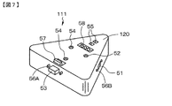
- FIG. 7 is a schematic perspective view of a power storage unit including a casing having a regular triangular prism shape.
- FIG. 8A and 8B are a schematic perspective view of a power storage unit including a casing having a quadrangular prism shape, and a bottom view of a power storage unit group in which three of the power storage units are combined. It is the conceptual diagram seen from the side.
- FIG. 9 is a diagram illustrating a power path in a power storage unit group in which six power storage units are combined in the eighth embodiment.
- FIG. 10 is a diagram illustrating the configuration of the hybrid vehicle of the ninth embodiment.
- Example 1 (according to the first aspect of the present disclosure, the power storage unit group, the charging method of the power storage unit group, the charger and the electronic device according to the first aspect of the present disclosure, and the first aspect of the present disclosure) Power supply / receipt method) 3.
- Example 2 (Modification of Example 1) 4).
- Example 3 (another modification of Example 1) 5.
- Example 4 (according to the second aspect of the present disclosure, the discharging method of the electric storage unit group, the charger and the electronic device according to the second aspect of the present disclosure, and the second aspect of the present disclosure) Power supply / receipt method) 6).
- Example 5 (Modification of Example 4) 7.
- Example 6 (another modification of Example 4) 8).
- Example 7 (another modification of Example 4) 9.
- Example 8 (Charging / Discharging Route Determination Method in Power Storage Unit Group) 10.
- Example 9 (electric vehicle according to the first and second aspects of the present disclosure), other
- Each power storage unit has a short circuit
- the power storage unit connected to the downstream side of the one power storage unit is charged via the short circuit in the one power storage unit. It can be set as a structure.
- Each power storage unit has a short circuit, In the charging step, if the secondary battery cell constituting the one power storage unit is fully charged, it is connected to the downstream side of the one power storage unit via a short circuit in the one power storage unit. The power storage unit can be charged.
- the charging method of the power storage unit group of the present disclosure including the above preferable configuration, or the power storage unit group of the present disclosure including the above preferable mode and configuration until the one power storage unit is fully charged, It is desirable that the outflow of power to the power storage unit connected to the downstream side of the one power storage unit is prohibited or that the outflow of power is prohibited.
- the method for discharging a power storage unit group of the present disclosure it is preferable to repeat the discharge process until the voltages of the secondary battery cells constituting all the power storage units become equal to or lower than a predetermined voltage.
- Each power storage unit has a short circuit, If the voltage of the secondary battery cell constituting the one power storage unit is equal to or lower than a predetermined voltage, it is connected to the upstream side of the one power storage unit via a short circuit in the one power storage unit. It can be set as the structure by which discharge of an electrical storage unit is started.
- Each power storage unit has a short circuit
- the first power storage unit upstream via the short circuit in the one power storage unit It can be set as the structure which starts discharge of the electrical storage unit connected to.
- the discharge from the power storage unit connected to the upstream side of the one power storage unit is prohibited during the discharge or the discharge is prohibited.
- the method for discharging the power storage unit group according to the second aspect of the present disclosure including the preferred form and configuration described above or the power storage unit group of the present disclosure, Connected to a power source for charging the storage unit upstream of the storage unit group, If the secondary battery cell constituting one power storage unit is fully charged, charging of the one power storage unit is stopped, or alternatively, charging is stopped and the one power storage unit is passed through the one power storage unit. A power storage unit connected to the downstream side of one power storage unit is charged, or alternatively, a charging step of charging the power storage unit can be provided.
- the power storage unit (A) a casing having a polygonal column shape; (B) a secondary battery cell stored inside the housing, (C) Charge / discharge control means stored in the housing and connected to the secondary battery cell; (D) at least one power input unit arranged in the housing and connected to the charge / discharge control means; and (E) It can be configured to include at least one power output unit arranged in the housing and connected to the charge / discharge control means.
- the power storage unit having such a configuration is referred to as “power storage unit in the present disclosure” for convenience.
- the shape of the housing of the power storage unit in the present disclosure is a polygonal column, and a plurality of power storage units can be combined. Moreover, since at least one power input unit and power output unit are arranged in the casing, a plurality of power storage units can be easily combined by connecting the power input unit and the power output unit in adjacent power storage units. Can do. In addition, for example, a plurality of power storage units having different capacities can be combined, that is, in a mixed state, and used as one power storage unit group as a whole. Can be dealt with flexibly. Further, for example, a plurality of various power storage units having different degrees of deterioration, usage time, number of times of charging, etc. can be combined, that is, in a mixed state, and can be used as one power storage unit group as a whole, capacity, voltage, etc. As a whole, one power storage unit group can be constructed using different secondary battery cells.
- the power storage unit group according to the first aspect or the second aspect of the present disclosure having the various preferable forms and configurations described above, the charger according to the first aspect or the second aspect of the present disclosure, the present disclosure
- the present invention can be applied to the electronic device according to the first aspect or the second aspect of the present invention, the electric vehicle according to the first aspect or the second aspect of the present disclosure, and the charging method and discharge of the power storage unit group according to the present disclosure. It can also be applied to the method, the power supply / reception method according to the first and second aspects of the present disclosure, and the charge / discharge route determination method in the power storage unit group.
- the number of power supply units is not particularly limited.
- the upstream side and the downstream side of the power storage unit group mean a side where current flows and a side where current flows when the power storage unit group is viewed as a whole, and current flows into the power storage unit. Means the side from which current flows.
- the predetermined voltage can be exemplified by 12 volts, but is not limited to this value.
- the power storage unit group is connected to the power consuming device.
- one or more power consuming devices may be connected to one place of the power storage unit group, or one or more power supply devices may be connected to a plurality of places of the power storage unit group.
- a power consuming device may be connected.
- wiring may be used, for example, a wireless power transmission method (wireless power transmission circuit) such as an electromagnetic induction method or a magnetic field resonance method may be employed.
- Power consumption devices include personal computers, television receivers, various display devices, mobile phones, PDAs, digital still cameras and video cameras, camcorders, music players, and other electronic devices, power tools such as electric drills, room lights, etc.
- Illumination fixtures, power storage units or home energy servers (household power storage devices), medical equipment, toys and the like can be exemplified, but are not limited thereto.
- these electric power consumption apparatuses can be mentioned as an electronic device of this indication, and the well-known components which comprise these electronic devices can be mentioned as an electronic component with which the electronic device was equipped. For example, it is driven and operated by the unit group.
- Examples of the electric vehicle include an electric vehicle, an electric motorcycle, an electric bicycle, and a Segway (registered trademark), and a power storage unit group including an electric power driving force conversion device (specifically, for example, for power)
- the present invention can be applied not only to driving a motor) but also to driving an electric power / driving force converter (specifically, for example, a power motor) for an aircraft or a ship.
- Examples of the power source in the present disclosure include a commercial power source, a power generation device, a power transmission network, and a smart grid (next-generation power transmission network).
- Examples of the power generation device include various solar cells, fuel cells, wind power generation devices, micro hydroelectric power generation devices, geothermal power generation devices, and the like, but are not limited thereto.
- the power generation device may be connected to one place of the power storage unit group or may be connected to a plurality of places of the power storage unit group. Further, the number of power generation devices is not limited to one and may be plural.
- wiring may be used, for example, a wireless power transmission method (wireless power transmission circuit) such as an electromagnetic induction method or a magnetic field resonance method may be employed.
- the charge / discharge control means may be configured by an integrated circuit for charge / discharge control and a DC / DC converter.
- the output voltage of the power storage unit can be stably output as a constant voltage.
- the charge / discharge control integrated circuit and the DC / DC converter, and the charge / discharge control integrated circuit and the DC / DC converter can be configured by a known charge / discharge control integrated circuit and DC / DC converter.
- the control device controls the plurality of power storage units, exchanges information between the plurality of power storage units, exchanges, etc. It is possible to check the operating state of the power storage unit, display the operating state of a plurality of power storage units, and the like.
- the power input unit can also serve as an information input unit
- the power output unit can also serve as an information output unit.
- a communication means a normal telephone line including an Internet communication network, an optical fiber line, ZigBee, wireless, LAN, RC232 Examples include, but are not limited to, Bluetooth and HomeRF, which are one of infrared, wireless LAN protocols including USB and IrDA, or a combination thereof.
- a personal computer can be mentioned as the control device or as a part of the control device. Moreover, it can also be set as the structure further provided with the portable terminal provided with the display apparatus, and the control apparatus and the portable terminal being connected by the communication means. With such a configuration, the operating state of the power storage unit or the power storage unit group can be confirmed at a remote location.
- the mobile terminal include a mobile phone, a PDA (Personal Digital Assistant), and a notebook personal computer, but are not limited thereto.
- the power input unit is configured by a USB terminal unit
- the power output unit is configured by a USB terminal unit that is fitted to the power input unit configured by the USB terminal unit. It can be made into the form currently made.
- the power input unit and the power output unit are configured by a wireless power transmission circuit. You can also.
- specific examples of the wireless power transmission circuit include the above-described various systems, but are not limited thereto.
- the housing has a configuration in which a plurality of housings can be arranged without gaps.
- a cross-sectional shape when the casing is cut in a virtual plane orthogonal to the axis of the casing having a polygonal column shape a triangle including a regular triangular prism; a square, a rectangle, a quadrilateral including a parallelogram;
- An arbitrary shape surrounded by a line segment or a curve can be exemplified.
- the cross-sectional shape is square or rectangular, the shape of the housing may be a cube or a rectangular parallelepiped.
- the casing is, for example, a plastic material, for example, a thermoplastic resin, specifically, a polyolefin resin such as polyethylene resin or polypropylene resin; a polyamide resin such as polyamide 6, polyamide 66, or polyamide MXD6; polyoxymethylene (Polyacetal, POM) resin; Polyester resin such as polyethylene terephthalate (PET) resin and polybutylene terephthalate (PBT) resin; Polyphenylene sulfide resin; Styrene resin such as polystyrene resin, ABS resin, AES resin and AS resin; Methacrylic resin Polycarbonate resin; modified polyphenylene ether (PPE) resin; polysulfone resin; polyethersulfone resin; polyarylate resin; polyetherimide resin; Bromide resins; polyether ketone resins; polyether ether ketone resins; polyester carbonate resin; may be produced from a liquid crystal polymer such as, but not limited thereto.
- a thermoplastic resin
- the casing has a regular hexagonal prism shape.
- the power input unit is provided on the odd-numbered side surface of the casing having the regular hexagonal column shape
- the power output unit is provided on the even-numbered side surface of the casing having the regular hexagonal column shape. It can be set as the structure which has.
- the power input unit may be provided on all of the odd-numbered side surfaces of the casing having a regular hexagonal column shape, or may be provided on a part of the side surfaces.
- the power output unit may be provided on all even-numbered side surfaces of the case having a regular hexagonal prism shape, or may be provided on a part of the side surfaces.
- an input display unit that is connected to the charge / discharge control unit and displays the presence / absence of power input is provided in the vicinity of the power input unit. It can be set as the structure by which the output display means which displays the presence or absence of electric power output connected to the charging / discharging control means is arrange
- the input display unit and the output display unit can be configured to include a display unit made of a member that transmits arrow-shaped light, and a light-emitting element arranged inside the display unit.
- the input display unit and the output display unit may be arranged on the top surface of the housing.
- a plurality of power storage units can be provided by connecting a power input unit and a power output unit in adjacent power storage units as a form of arrangement of the power storage units.
- the form which combined these can be mentioned and the electrical storage unit group is comprised by this.
- a plurality of power storage units may be combined in a plane to form a power storage unit group, or a plurality of power storage units may be combined in a three-dimensional or stacked manner to form a power storage unit group.
- a plurality of power storage units may be combined in a plane and further combined in a three-dimensional (or stacked) manner.
- the capacity, size (size) of the power storage units constituting the power storage unit group, the number, output voltage, capacity, etc. of the secondary battery cells constituting the power storage units may be the same or different in the power storage units. Also good.
- Embodiment 1 is a power storage unit group, a charger and an electronic device according to the first aspect of the present disclosure, a charging method for the power storage unit group according to the present disclosure, and a power supply / reception method according to the first aspect of the present disclosure.
- FIG. 1A is a schematic view of a storage unit group in which six storage units according to the present disclosure are combined, viewed from above.
- the charging method of the storage unit group of Example 1 and the power supply / It is a figure which shows the path
- FIG. 2A a schematic perspective view of a power storage unit group in which three power storage units in Example 1 are combined is shown in FIG. 2A, and a schematic view of the power storage unit group viewed from above is shown in FIG.
- FIG. 2C shows a schematic diagram when the inside of the power storage unit is viewed.
- a block diagram of the charge / discharge control means is shown in FIG.
- the power storage unit group of Example 1 is a power storage unit group 10 in which a plurality of power storage units 11 having secondary battery cells 30 are connected in a linear shape or a network shape,
- the power storage unit group 10 is connected to a power source for charging the power storage unit 11 on the upstream side of the power storage unit group 10.
- the secondary battery cell 30 constituting one power storage unit 11 is fully charged, the charging of the one power storage unit 11 is stopped, and the one power storage unit is passed through the one power storage unit 11.
- the power storage unit 11 connected to the downstream side of 11 is charged.
- the charger of Example 1 is a charger that includes a power storage unit group 10 in which a plurality of power storage units 11 each having a secondary battery cell 30 are connected in a straight line shape or a net shape,
- the power storage unit group 10 is connected to a power source for charging the power storage unit 11 on the upstream side of the power storage unit group 10.
- the secondary battery cell 30 constituting one power storage unit 11 is fully charged, the charging of the one power storage unit 11 is stopped, and the one power storage unit is passed through the one power storage unit 11.
- the power storage unit 11 connected to the downstream side of 11 is charged.
- the electronic device of Example 1 is A plurality of power storage units 11 each having a secondary battery cell 30 connected in a straight line or a network, and An electronic component to which power is supplied from the power storage unit group 10; Is an electronic device.
- the power storage unit group 10 is connected to a power source for charging the power storage unit 11 on the upstream side of the power storage unit group 10, and is connected to an electronic component on the downstream side of the power storage unit group 10,
- the secondary battery cell 30 constituting one power storage unit 11 is fully charged, the charging of the one power storage unit 11 is stopped, and the one power storage unit is passed through the one power storage unit 11.
- the power storage unit 11 connected to the downstream side of 11 is charged.
- a personal computer can be illustrated as an electronic device, and a central processing unit etc. can be illustrated as an electronic component with which this electronic device was equipped. The same applies to the electronic device of Example 4 to be described later.
- the power storage unit group (power supply unit group) 10 is, as described above, the power storage unit (power supply unit) including the secondary battery cells 30. Unit) 11, and the power storage units 11 are connected in a mesh pattern.
- the power storage unit group 10 is composed of a plurality of power storage units 11 arranged in a cluster on a plane.
- the power storage unit 11 of Example 1 or Examples 2 to 9 described later is (A) a housing 20 having a polygonal column shape; (B) the secondary battery cell 30 stored in the housing 20; (C) Charge / discharge control means 40 stored in the housing 20 and connected to the secondary battery cell 30; (D) at least one power input unit 51 arranged in the housing 20 and connected to the charge / discharge control means 40, and (E) at least one power output unit 53 disposed in the housing 20 and connected to the charge / discharge control means 40;
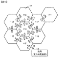
- the power storage unit group 10 includes six power storage units 11A, 11B, 11C, 11D, 11E, as shown in FIG.
- the power storage unit group 10 is configured by combining 8 power storage units as shown in FIG. As shown in FIG. 9, the power storage unit group 10 is configured by combining five power storage units, but the number of power storage units is not limited to this.
- the shape of the casing 20 has a shape that allows a plurality of casings 20 to be arranged without gaps.
- the housing 20 has a regular hexagonal prism shape. That is, the cross-sectional shape when the casing 20 is cut along a virtual plane orthogonal to the axis of the casing 20 is a regular hexagon.
- the power input unit 51 is provided on the odd-numbered side surface of the casing 20 having a regular hexagonal column shape
- the power output unit 53 is provided on the even-numbered side surface of the casing 20 having a regular hexagonal column shape. It has been. In the illustrated example, there are three power input units 51 and three power output units 53, but the configuration is not limited thereto.
- the power input unit 51 and the power output unit 53 are connected to the charge / discharge control means 40 via a wiring (not shown).
- the three power storage units 11 have different heights, but the three power storage units 11 have different capacities, that is, stored in the housing 20. This is because the number of secondary battery cells 30 is different.
- the casing 20 is molded from a plastic material such as ABS resin.
- the information input unit and the information output unit are specifically composed of a USB terminal unit 55. More specifically, for example, the information input unit includes a USB terminal, and the information output unit includes a USB socket.
- the USB terminal portion 55 is connected to the charge / discharge control means 40 via a wiring (not shown).
- the information storage unit 11 can exchange information by connecting the information input unit and the information output unit with a USB cable among the plurality of power storage units 11.
- the power input unit 51 may be configured from a USB terminal unit
- the power output unit 53 may be configured from a USB terminal unit that fits into the power input unit 51 configured from a USB terminal.
- the power input unit 51 and the power output unit 53 are configured from a micro USB terminal and a micro USB socket, or the power output unit 53 and the power input unit 51 are configured from a micro USB terminal and a micro USB socket. do it.
- Each power storage unit 11 is provided with a short circuit (not shown). Specifically, the power input unit 51 and the power output unit 53 are short-circuited.
- the conduction / non-conduction of the short circuit is controlled by the charge / discharge control means 40.
- a switch circuit may be provided in the short circuit, and the on / off operation of the switch circuit may be controlled by the charge / discharge control means 40.
- it is not limited to such a configuration.
- the charge / discharge control means 40 includes a well-known integrated circuit (charge circuit) 43 for charge / discharge control and a well-known DC / DC. It comprises a converter (DC / DC converter for output) 44.
- the charge / discharge control means 40 further includes an MPU 41, a storage means 42 comprising an EEROM, a control system DC / DC converter 45, and a USB DC / DC converter 46.
- input power having a voltage of 12 volts is supplied to the integrated circuit (charging circuit) 43 from an external power source such as a commercial power source or a solar battery via the power input unit 51.
- the secondary battery cell 30 which consists of a lithium ion secondary battery is charged by the well-known operation
- FIG. Power is supplied from the secondary battery cell 30 to the MPU 41 and the storage means 42 via the control system DC / DC converter 45. Further, electric power is supplied from the secondary battery cell 30 to the outside through the output DC / DC converter 44 and the power output unit 53, and also to the USB terminal unit 55 through the USB DC / DC converter 46. Power is supplied.
- the MPU 41 and the like are attached to the printed wiring board 47.
- the power input unit 51 and the power output unit 53 have a structure that fits together. Specifically, for example, the power input unit 51 has a protruding structure, and the power output unit 53 has a concave structure. And in the electrical storage unit 11 which adjoins, the electrical storage unit group 10 with which the several electrical storage unit 11 was combined can be obtained by making the electric power input part 51 and the electric power output part 53 fit.
- the charge / discharge control means 40 has a structure that can detect the fitting state between the power input section 51 and the power output section 53 by a detection means (for example, a switch) not shown.
- an input display unit 52 that displays the presence / absence of power input connected to the charge / discharge control unit 40 is disposed in the vicinity of the power input unit 51, and in the vicinity of the power output unit 53.
- output display means 54 connected to the charge / discharge control means 40 for displaying the presence or absence of power output.
- the input display unit 52 and the output display unit 54 include a display unit made of a member that transmits arrow-shaped light, and a light emitting element (not shown) disposed inside the display unit.
- the light emitting element can be specifically composed of, for example, an LED.
- the input display means 52 and the output display means 54 are disposed on the top surface of the housing 20.
- the light emitting element is connected to the charge / discharge control means 40 via a wiring, and the on / off of the light emitting element is controlled by the charge / discharge control means 40. More specifically, the charge / discharge control means 40 checks the fitting state between the power input unit 51 and the power output unit 53, and further determines the flow of current between the power input unit 51 and the power output unit 53. Based on the detection result, on / off control of the light emitting element is performed.
- FIGS. 1A, 1B, 5A, and 5B show three input display means 52 and three output display means 54 for one power storage unit 11.
- input display means in which power flows or can flow in power flows out or Only the output display means from which power can flow is shown.
- the input display means 52 indicated by the black arrow is connected to the power input unit 51 located in the vicinity thereof. This indicates that power can be supplied (input) from the power source, and the output display means 54 indicated by a black arrow is used to supply power from the power output unit 53 located in the vicinity thereof to the outside or the adjacent power storage unit 11. Can be supplied (output).
- the input display means 52 indicated by a hatched arrow indicates that power is not supplied (input) from an external power source to the power input unit 51 located in the vicinity thereof.
- the output display means 54 indicated by the hatched arrow is prohibited from supplying (outputting) power to the outside or the adjacent power storage unit 11 from the power output unit 53 located in the vicinity thereof. Is shown.
- the housing 20 of the power storage unit 11 has a charge state display means (not shown) comprising an LED for displaying a charge state, a discharge state display means or an remaining amount display means (not shown) comprising an LED for displaying a discharge state. May be connected to the charge / discharge control means 40, and the operation may be controlled by the charge / discharge control means 40.
- the input display unit 52 and the output display unit 54 may be used as a charge state display unit, a discharge state display unit, or a remaining amount display unit. In this case, for example, the function as the charge state display means, the discharge state display means, or the remaining amount display means can be exhibited by the blinking state of the light emitting element.
- a single power input is provided. Electric power is supplied from an external power source via the unit 51 to charge the secondary battery cells 30 in the five, six, or eight power storage units 11. Further, power is supplied (output) to the power consuming device via one power output unit 53, and the power consuming device is driven.
- an external power source via the unit 51 to charge the secondary battery cells 30 in the five, six, or eight power storage units 11. Further, power is supplied (output) to the power consuming device via one power output unit 53, and the power consuming device is driven.
- power consuming device is driven.
- the shape of the housing 20 of the power storage unit 11 is a polygonal column (specifically, a regular hexagonal column). Can be combined without gaps. Further, by connecting the power input unit 51 and the power output unit 53 in the adjacent power storage units 11, a plurality of power storage units 11 can be easily combined. For example, various power storage units 11 having different capacities can be combined. In combination, that is, in a mixed state, the power storage unit group 10 can be used as a whole.
- the power storage unit 11 Is permanently or temporarily assigned an identification number (ID).
- ID an identification number
- a method of assigning a permanent identification number a method in which a user sets a MAC address (Media Access Control address) or a DIP switch disposed in a power storage unit can be exemplified.
- a temporary identification number assigning method for example, a power storage unit connected to a power source or a power storage unit connected to a power consuming device is referred to as a so-called parent power storage unit.
- a method of assigning an identification number to the power storage unit can be exemplified, and a method of assigning an identification number to the power storage unit by a control device described later can be exemplified.
- each power storage unit 11 under its control of the charge / discharge control means 40, as necessary, Processing related to charging and discharging is performed, the short circuit is controlled by itself, the remaining amount is measured, and the remaining amount is evaluated in n stages. Furthermore, each power storage unit 11 can display an identification number (ID), remaining amount information, already charged ID history, uncharged ID history, already discharged ID history, undischarged ID history, ready to start charging, etc. as necessary. Communicate and exchange with each other.
- ID identification number
- the power storage unit group 10 is a power source for charging the power storage unit 11 on the upstream side of the power storage unit group 10. 12 is connected.
- the power input unit A 1 of the electric power storage unit 11A is connected to the power source 12.
- a commercial power source can be used as the power source 12, and for example, a solar cell can be used.
- the connection between the power storage unit group 10 and the power source 12 may use the wiring 13 or may adopt a wireless power transmission method (wireless power transmission circuit) such as an electromagnetic induction method or a magnetic field resonance method.
- the power storage unit 11A is a parent power storage unit, and the remaining five power storage units 11B, 11C, 11D, 11E, and 11F are child storage units.
- various processes are performed by the charge / discharge control unit 40, but for convenience, the power storage unit is expressed as performing various processes.
- power storage unit-A When a new power storage unit (referred to as “power storage unit-A”) is newly connected to the power storage unit group, the power storage unit adjacent to the power storage unit-A (that is, directly connected to the power storage unit-A) (For convenience, referred to as “power storage unit-B”) refers to the identification numbers (ID) of all the power storage units owned by itself, generates a new identification number, and assigns the identification number to power storage unit-A.
- ID identification numbers
- the power storage unit-A is notified of the identification number of the parent power storage unit.
- the power storage unit-A can know that the parent power storage unit has already been determined.
- the power storage unit-A sends a signal that prompts the parent power storage unit to update the information.
- the parent power storage unit that has received the signal that prompts the update of information transmits a list of identification numbers of all the power storage units to all the power storage units.
- power storage unit-C When a certain power storage unit (referred to as “power storage unit-C”) is removed from the power storage unit group, the power storage unit adjacent to power storage unit-C (ie, directly connected to power storage unit-C) (for convenience) , Referred to as “power storage unit-D”) transmits a signal for urging information to be updated together with the identification number of power storage unit-C to the parent power storage unit.
- the parent power storage unit updates the identification number list and transmits the identification number list to all the power storage units.
- the parent power storage unit is removed, if there are multiple power storage units directly connected to the parent power storage unit, the power storage unit with the smallest identification number becomes the parent power storage unit and is directly connected to the parent power storage unit.
- this directly connected power storage unit becomes the parent power storage unit.
- the new parent power storage unit deletes the identification number of the original parent power storage unit from the identification number list, and transmits its own identification number as the parent power storage unit identification number to all power storage units.
- a power storage unit having secondary battery cells supplies power from a plurality of power storage unit groups 10 connected in a straight line or network, and power is supplied from a power generation device and a power transmission network (including smart grids and next-generation power transmission networks).
- Power supply / receipt method to receive The power storage unit group 10 is connected to a power generator for charging the power storage unit on the upstream side of the power storage unit group via a power transmission network, and connected to a load (power consuming device) 14 on the downstream side of the power storage unit group.
- Reference numeral 15 represents wiring.
- the power storage unit 11A which is the parent power storage unit, inquires to the five child power storage units 11B, 11C, 11D, 11E, and 11F whether or not the preparation for starting charging has been completed, and all the power storage units 11A, 11B, 11C, 11D, 11E, When 11F completes preparation for starting charging, charging of the secondary battery cell 30 in the power storage unit 11A is started.
- Step-110 If the power storage unit (one power storage unit) 11A is fully charged, the power storage unit 11A stops charging. Then, the power storage unit 11B connected to the downstream side of the power storage unit (one power storage unit) 11A is charged via the power storage unit (one power storage unit) 11A.
- a short circuit is made into a conduction
- All the power storage units store “11A” as the already charged ID history, and the power storage unit 11A selects the power storage unit based on the content of the uncharged ID history (“11B”), that is, selects the power storage unit 11B. Then, charging of the power storage unit 11B is started. Note that the parent power storage unit 11A is notified that the power storage unit 11A is fully charged.
- the power storage unit 11B corresponds to “one power storage unit”.
- the power storage units having the power input units 51 (C 1 , D 3 ) connected to the power output units 53 (B 4 , B 6 ) of the power storage unit 11B are the power storage unit 11C and the power storage unit 11D. Therefore, the power storage unit 11C and the power storage unit 11D correspond to “a power storage unit connected to the downstream side of one power storage unit”.
- the power storage unit 11B stores “11C, 11D” as the uncharged ID history. In addition, until the power storage unit (one power storage unit) 11B is fully charged, the charging power is discharged to the power storage unit 11C and the power storage unit 11D connected to the downstream side of the power storage unit (one power storage unit) 11B. It is forbidden. Specifically, the outflow of power from the power output units B 4 and B 6 is prohibited.
- Step-120 If the power storage unit (one power storage unit) 11B is fully charged, the power storage unit 11B stops charging. Then, the power storage unit 11C and the power storage unit 11D connected to the downstream side of the power storage unit (one power storage unit) 11B are charged via the power storage unit (one power storage unit) 11B. In addition, before starting charge of the electrical storage unit 11C and the electrical storage unit 11D, a short circuit is made into a conduction
- All the power storage units store “11A, 11B” as the already-charged ID history, and the power storage unit 11B selects the power storage unit based on the contents of the uncharged ID history (“11C, 11D”), that is, the power storage The unit 11C and the power storage unit 11D are selected to notify the parent power storage unit 11A that the power storage unit 11B is fully charged.
- the power storage unit 11C and the power storage unit 11D correspond to “one power storage unit”.
- the power storage unit having the power input unit 51 (E 3 ) connected to the power output unit 53 (C 6 ) of the power storage unit 11C is the power storage unit 11E.
- the power storage units having the power input units 51 (A 5 , E 1 ) connected to the power output units 53 (D 2 , D 4 ) of the power storage unit 11D are the power storage unit 11A and the power storage unit 11E.
- the power storage unit 11E corresponds to “a power storage unit connected downstream of one power storage unit”.
- the unit 11A is excluded from “the power storage unit connected to the downstream side of the one power storage unit”. That is, a power storage unit that has already been charged is excluded from “a power storage unit connected downstream of one power storage unit”. The same applies to the following description. This can prevent the occurrence of a charging loop in the charging route.
- the power storage unit 11E corresponds to “a power storage unit connected to the downstream side of one power storage unit”.
- the power storage unit 11C and the power storage unit 11D store “11E” as the uncharged ID history.
- the electric power for charging to the power storage unit 11E connected to the downstream side of the power storage unit (one power storage unit) 11C is prohibited until the power storage unit (one power storage unit) 11C is fully charged.
- power drain from the power output unit C 6 is prohibited.
- outflow of charging power to the power storage unit 11E connected to the downstream side of the power storage unit (one power storage unit) 11D is prohibited until the power storage unit (one power storage unit) 11D is fully charged. .
- power drain from the power output unit D 4 is prohibited.
- Step-130 If the power storage unit (one power storage unit) 11C and the power storage unit 11D are fully charged, the power storage unit 11C and the power storage unit 11D stop charging. Then, the power storage unit 11E connected to the downstream side of the power storage unit (one power storage unit) 11C is charged via the power storage unit (one power storage unit) 11C.
- the power storage unit 11C and the power storage unit 11D store “11E” as the uncharged ID history, but are based on the information of the power storage unit having a young identification number.
- a short circuit is made into a conduction
- the power input unit C 1 and the power output unit C 6 are short-circuited. Further, control is performed so that charging power does not flow from the power storage unit 11D to the power storage unit 11E.
- the storage unit 11E connected to the downstream side of the storage unit (one storage unit) 11C and the storage unit 11D via the two storage units of the storage unit (one storage unit) 11C and the storage unit 11D. You may charge.
- All the power storage units store “11A, 11B, 11C, 11D” as the already-charged ID history, and the power storage unit 11C selects the power storage unit based on the contents of the uncharged ID history (“11E”). Then, the power storage unit 11E is selected, and charging of the power storage unit 11E is started. In addition, the parent power storage unit 11A is notified that the power storage unit 11C and the power storage unit 11D are fully charged.
- the power storage unit 11E corresponds to “one power storage unit”.
- the power storage units having the power input units 51 (B 5 , F 1 ) connected to the power output units 53 (E 2 , E 4 ) of the power storage unit 11E are the power storage unit 11B and the power storage unit 11F.
- the power storage unit 11F corresponds to “a power storage unit connected downstream of one power storage unit”.
- the unit 11B is excluded from “the power storage unit connected to the downstream side of the one power storage unit”.
- the power storage unit 11F corresponds to “a power storage unit connected to a downstream side of one power storage unit”.
- the power storage unit 11E stores “11F” as the uncharged ID history.
- the electric power for charging to the power storage unit 11F connected to the downstream side of the power storage unit (one power storage unit) 11E is prohibited until the power storage unit (one power storage unit) 11E is fully charged. Specifically, the outflow of power from the power output unit E 4 is prohibited.
- Step-140 If the power storage unit (one power storage unit) 11E is fully charged, the power storage unit 11E stops charging. Then, the power storage unit 11F connected to the downstream side of the power storage unit (one power storage unit) 11E is charged via the power storage unit (one power storage unit) 11E. In addition, before starting charge of the electrical storage unit 11F, a short circuit is made into a conduction
- All the power storage units store “11A, 11B, 11C, 11D, 11E” as the already-charged ID history, and the power storage unit 11E selects the power storage unit based on the contents of the uncharged ID history (“11F”). That is, the power storage unit 11F is selected and charging of the power storage unit 11F is started. Note that the parent power storage unit 11A is notified that the power storage unit 11E is fully charged.
- the power storage unit having the power input unit 51 connected to the power output unit 53 of the power storage unit 11F is the power storage unit 11C.
- the power storage unit 11C since “11C” is included in the already-charged ID history stored in the power storage unit 11F, the power storage unit 11C is excluded from “a power storage unit connected downstream from one power storage unit”. Therefore, since there is no “power storage unit connected downstream from one power storage unit”, the power storage unit 11F stores “NULL” as an uncharged ID history. Then, when the power storage unit 11F is fully charged, the power storage unit 11F stops charging.
- the power storage unit 11A which is the parent power storage unit, checks the already-discharged ID history, and checks whether there is a power storage unit that has not yet been charged. In Example 1, since all the power storage units have completed charging, the charging process is completed. Thus, the repetition of the charging process until the secondary battery cells constituting all the power storage units were fully charged was completed.
- the second embodiment is a modification of the first embodiment.
- the power input unit A 1 of the power storage unit 11A is connected to the power source 12.
- Example 2 as shown in FIG. 1 (B), the power input portion D 1 of the electric power storage unit 11D is connected to the power source 12.
- the power storage unit 11D is a parent power storage unit, and the remaining five power storage units 11A, 11B, 11C, 11E, and 11F are child power storage units.
- the power storage unit 11D which is the parent power storage unit, inquires to the five child power storage units 11A, 11B, 11C, 11E, and 11F whether the preparation for starting charging has been completed, and all the power storage units 11A, 11B, 11C, 11D, 11E, When 11F completes preparation for starting charging, charging of the secondary battery cell 30 in the power storage unit 11D is started.
- the power storage unit 11D corresponds to “one power storage unit”.
- the power storage units having the power input units 51 (A 5 , E 1 ) connected to the power output units 53 (D 2 , D 4 ) of the power storage unit 11D are the power storage unit 11A and the power storage unit 11E. Accordingly, the power storage unit 11A and the power storage unit 11E correspond to “a power storage unit connected to the downstream side of one power storage unit”.
- the power storage unit 11D stores “11A, 11E” as the uncharged ID history.
- the charging power is discharged to the power storage unit 11A and the power storage unit 11E connected to the downstream side of the power storage unit (one power storage unit) 11D. It is forbidden. Specifically, the outflow of power from the power output units D 2 and D 4 is prohibited.
- Step-210 If the power storage unit (one power storage unit) 11D is fully charged, the power storage unit 11D stops charging. Then, the power storage unit 11A and the power storage unit 11E connected to the downstream side of the power storage unit (one power storage unit) 11D are charged via the power storage unit (one power storage unit) 11D. In addition, before starting charge of the electrical storage unit 11A and the electrical storage unit 11E, a short circuit is made into a conduction
- All the power storage units store “11D” as the already-charged ID history, and the power storage unit 11D selects the power storage unit based on the contents of the uncharged ID history (“11A, 11E”), that is, the power storage unit 11A. And the storage unit 11E is selected, and charging of the storage unit 11A and the storage unit 11E is started. Note that the parent power storage unit 11D is notified that the power storage unit 11D is fully charged.
- the power storage unit 11A corresponds to “one power storage unit”.
- Power storage unit having a power storage unit 11A of the power output unit 53 power is connected to (A 4) input unit 51 (B 1) is a power storage unit 11B.
- the power storage unit 11E corresponds to “one power storage unit”.
- Power storage unit having a power storage unit 11E of the power output section 53 (E 2, E 4) connected to the power input unit 51 (B 5, F 1) is a power storage unit 11B and the power storage unit 11F. Therefore, the power storage unit 11B and the power storage unit 11F correspond to “power storage units connected to the downstream side of one power storage unit”.
- the power storage unit 11A stores “11B” as the uncharged ID history.
- the electric power for charging to the power storage unit 11B connected to the downstream side of the power storage unit (one power storage unit) 11A is prohibited until the power storage unit (one power storage unit) 11A is fully charged. Specifically, the outflow of power from the power output unit A 4 is prohibited.
- the power storage unit 11E stores “11B, 11F” as the uncharged ID history.
- the electric power for charging to the power storage unit 11F connected to the downstream side of the power storage unit (one power storage unit) 11E is prohibited until the power storage unit (one power storage unit) 11E is fully charged. Specifically, the outflow of power from the power output units E 2 and E 4 is prohibited.
- Step-220 If the power storage unit (one power storage unit) 11A and the power storage unit 11E are fully charged, the power storage unit 11A and the power storage unit 11E stop charging. Then, the power storage unit 11B connected to the downstream side of the power storage unit (one power storage unit) 11A is charged via the power storage unit (one power storage unit) 11A. In addition, the power storage unit 11F connected downstream of the power storage unit (one power storage unit) 11E is charged via the power storage unit (one power storage unit) 11E. In addition, before starting charge of the electrical storage unit 11B and the electrical storage unit 11F, in the electrical storage unit (one electrical storage unit) 11A and the electrical storage unit 11E, a short circuit is made into a conduction state. Specifically, the power input unit A 5 and the power output unit A 4 , and the power input unit E 1 and the power output unit E 4 are short-circuited.
- All the power storage units store “11D, 11A, 11E” as the already-charged ID history, and the power storage unit 11A selects the power storage unit based on the contents of the uncharged ID history (“11B”), that is, the power storage unit The unit 11B is selected, and charging of the power storage unit 11B is started. Note that the parent power storage unit 11D is notified that the power storage unit 11A is fully charged. On the other hand, the power storage unit 11E selects the power storage unit based on the contents of the uncharged ID history (“11B, 11F”), but the uncharged ID history “11B” already has a younger identification number than the power storage unit 11E.
- the power storage unit 11E Since the power storage unit 11A that is the power storage unit is selected, the power storage unit 11E is prohibited from selecting the power storage unit 11B. Accordingly, the power storage unit 11E selects the power storage unit 11F and starts charging the power storage unit 11F. The power storage unit 11E is notified to the parent power storage unit 11D that the power storage unit 11E is fully charged.
- the power storage unit 11B and the power storage unit 11F correspond to “one power storage unit”.
- the power storage units having the power input units 51 (C 1 , D 3 ) connected to the power output units 53 (B 4 , B 6 ) of the power storage unit 11B are the power storage unit 11C and the power storage unit 11D.
- the power storage unit having the power input unit 51 (C 5 ) connected to the power output unit 53 (F 2 ) of the power storage unit 11F is the power storage unit 11C.
- the power storage unit 11C corresponds to “a power storage unit connected downstream from one power storage unit”.
- the unit 11D is excluded from “the power storage unit connected to the downstream side of the one power storage unit”. Therefore, the power storage unit 11 ⁇ / b> C corresponds to “a power storage unit connected downstream of one power storage unit”.
- the power storage unit 11B stores “11C” as the uncharged ID history.
- the power storage unit 11F stores “11C” as the uncharged ID history.
- the electric power for charging to the power storage unit 11C connected to the downstream side of the power storage unit (one power storage unit) 11B is prohibited until the power storage unit (one power storage unit) 11B is fully charged.
- the outflow of power from the power output unit B 4 is prohibited.
- outflow of charging power to the power storage unit 11C connected to the downstream side of the power storage unit (one power storage unit) 11F is prohibited until the power storage unit (one power storage unit) 11F is fully charged. .
- the outflow of power from the power output unit F 2 is prohibited.
- Step-230 If the power storage unit (one power storage unit) 11B and the power storage unit 11F are fully charged, the power storage unit 11B and the power storage unit 11F stop charging.
- the power storage unit 11B and the power storage unit 11F store “11C” as the uncharged ID history, but are based on the information of the power storage unit having a young identification number. Therefore, the power storage unit 11C is charged via the power storage unit 11B.
- a short circuit is made into a conduction
- the charging power is controlled so as not to flow from the power storage unit 11F to the power storage unit 11C.
- the storage unit 11C connected to the downstream side of the storage unit (one storage unit) 11B and the storage unit 11F via the two storage units of the storage unit (one storage unit) 11B and the storage unit 11F. You may charge.
- All the power storage units store “11D, 11A, 11E, 11B, 11F” as the already charged ID history, and the power storage unit 11B selects the power storage unit based on the contents of the uncharged ID history (“11C”). That is, the power storage unit 11C is selected, and charging of the power storage unit 11C is started. The power storage unit 11B is notified to the parent power storage unit 11D that it is fully charged.
- the power storage unit 11C stores “NULL” as the uncharged ID history. Then, if the power storage unit 11C is fully charged, the power storage unit 11C stops charging.
- the power storage unit 11D which is the parent power storage unit, checks the already-discharged ID history and checks whether there is a power storage unit that has not yet been charged.
- the charging process is completed. Thus, the repetition of the charging process until the secondary battery cells constituting all the power storage units were fully charged was completed.
- Example 3 is also a modification of Example 1.
- the power storage unit group 10 is connected to the control device 16 via the communication unit 17.
- the storage unit group 10 is charged under the control of the control device 16.
- FIG. 4B is a conceptual diagram of the power storage unit group according to the third embodiment.
- control device 16 composed of a personal computer is connected to an information output unit in any one of the power storage units 11 by a USB cable, and controls the plurality of power storage units 11 by the control device 16 and stores information in the plurality of power storage units 11. It is possible to check the operating state of the plurality of power storage units 11, display and display the operating state of the plurality of power storage units 11, such as exchange and exchange. In addition, you may connect the control apparatus 16 and each electrical storage unit 11 via ZigBee, for example.
- Each power storage unit 11 performs processing related to charging and discharging under the control of the control device 16 and the charge / discharge control means 40, controls the short circuit, measures the remaining amount, and evaluates the remaining amount in n stages. Further, each power storage unit 11 transmits / receives an identification number (ID), remaining amount information, already charged ID history, uncharged ID history, completion of charge start preparation, and the like to and from the control device 16.
- ID identification number
- the control device 16 inquires the power storage units 11A, 11B, 11C, 11D, 11E, and 11F whether or not the preparation for starting charging is completed, and all the power storage units 11A, 11B, 11C, 11D, 11E, and 11F prepare for charging start. Is completed, charging of the secondary battery cell 30 in the power storage unit 11A is started.
- the power storage unit 11A corresponds to “one power storage unit”.
- the power storage unit 11B is the only power storage unit having the power input unit 51 (B 1 ) connected to the power output unit 53 (A 4 ) of the power storage unit 11A. Therefore, the power storage unit 11B corresponds to “a power storage unit connected to the downstream side of one power storage unit”.
- the control device 16 stores “11B” as the uncharged ID history.
- the electric power for charging to the power storage unit 11B connected to the downstream side of the power storage unit (one power storage unit) 11A is prohibited until the power storage unit (one power storage unit) 11A is fully charged. Specifically, the outflow of power from the power output unit A 4 is prohibited.
- Step-310 When the power storage unit (one power storage unit) 11A is fully charged, charging of the power storage unit 11A is stopped under the control of the control device 16. Then, the power storage unit 11B connected to the downstream side of the power storage unit (one power storage unit) 11A is charged via the power storage unit (one power storage unit) 11A. In addition, before starting charge of the electrical storage unit 11B, in the electrical storage unit (one electrical storage unit) 11A, a short circuit is made into a conduction
- control apparatus 16 memorize
- the power storage unit 11B corresponds to “one power storage unit”.
- the power storage units having the power input units 51 (C 1 , D 3 ) connected to the power output units 53 (B 4 , B 6 ) of the power storage unit 11B are the power storage unit 11C and the power storage unit 11D. Therefore, the power storage unit 11C and the power storage unit 11D correspond to “a power storage unit connected to the downstream side of one power storage unit”.
- the control device 16 stores “11C, 11D” as the uncharged ID history. In addition, until the power storage unit (one power storage unit) 11B is fully charged, the charging power is discharged to the power storage unit 11C and the power storage unit 11D connected to the downstream side of the power storage unit (one power storage unit) 11B. It is forbidden. Specifically, the outflow of power from the power output units B 4 and B 6 is prohibited.
- Step-320 If the power storage unit (one power storage unit) 11B is fully charged, the control device 16 stops charging the power storage unit 11B. Then, the power storage unit 11C and the power storage unit 11D connected to the downstream side of the power storage unit (one power storage unit) 11B are charged via the power storage unit (one power storage unit) 11B. In addition, before starting charge of the electrical storage unit 11C and the electrical storage unit 11D, a short circuit is made into a conduction
- control apparatus 16 memorize
- the power storage unit 11C and the power storage unit 11D correspond to “one power storage unit”.
- the power storage unit having the power input unit 51 (E 3 ) connected to the power output unit 53 (C 6 ) of the power storage unit 11C is the power storage unit 11E.
- the power storage units having the power input units 51 (A 5 , E 1 ) connected to the power output units 53 (D 2 , D 4 ) of the power storage unit 11D are the power storage unit 11A and the power storage unit 11E.
- the power storage unit 11E corresponds to “a power storage unit connected downstream of one power storage unit”.
- the unit 11A is excluded from “the power storage unit connected to the downstream side of the one power storage unit”. That is, a power storage unit that has already been charged is excluded from “a power storage unit connected downstream of one power storage unit”.
- the power storage unit 11E corresponds to “a power storage unit connected to the downstream side of one power storage unit”.
- the control device 16 stores “11E” as the uncharged ID history.
- the electric power for charging to the power storage unit 11E connected to the downstream side of the power storage unit (one power storage unit) 11C is prohibited until the power storage unit (one power storage unit) 11C is fully charged.
- power drain from the power output unit C 6 is prohibited.
- outflow of charging power to the power storage unit 11E connected to the downstream side of the power storage unit (one power storage unit) 11D is prohibited until the power storage unit (one power storage unit) 11D is fully charged. .
- power drain from the power output unit D 4 is prohibited.
- Step-330 When the power storage unit (one power storage unit) 11C and the power storage unit 11D are fully charged, charging of the power storage unit 11C and the power storage unit 11D is stopped under the control of the control device 16. Then, the power storage unit 11E connected to the downstream side of the power storage unit (one power storage unit) 11C is charged via the power storage unit (one power storage unit) 11C.
- the control device 16 stores “11E” as the uncharged ID history
- the control device 16 is based on the information of the power storage unit having a young identification number. Specifically, the power input unit C 1 and the power output unit C 6 are short-circuited. Further, control is performed so that charging power does not flow from the power storage unit 11D to the power storage unit 11E.
- the storage unit 11E connected to the downstream side of the storage unit (one storage unit) 11C and the storage unit 11D via the two storage units of the storage unit (one storage unit) 11C and the storage unit 11D. You may charge.
- control apparatus 16 memorize
- the power storage unit 11E corresponds to “one power storage unit”.
- the power storage units having the power input units 51 (B 5 , F 1 ) connected to the power output units 53 (E 2 , E 4 ) of the power storage unit 11E are the power storage unit 11B and the power storage unit 11F.
- the power storage unit 11F corresponds to “a power storage unit connected downstream of one power storage unit”.
- the unit 11B is excluded from “the power storage unit connected to the downstream side of the one power storage unit”.
- the power storage unit 11F corresponds to “a power storage unit connected to a downstream side of one power storage unit”.
- the control device 16 stores “11F” as the uncharged ID history.
- the electric power for charging to the power storage unit 11F connected to the downstream side of the power storage unit (one power storage unit) 11E is prohibited until the power storage unit (one power storage unit) 11E is fully charged. Specifically, the outflow of power from the power output unit E 4 is prohibited.
- Step-340 When the power storage unit (one power storage unit) 11E is fully charged, charging of the power storage unit 11E is stopped under the control of the control device 16. Then, the power storage unit 11F connected to the downstream side of the power storage unit (one power storage unit) 11E is charged via the power storage unit (one power storage unit) 11E. In addition, before starting charge of the electrical storage unit 11F, a short circuit is made into a conduction
- control apparatus 16 memorize
- the power storage unit having the power input unit 51 connected to the power output unit 53 of the power storage unit 11F is the power storage unit 11C.
- the power storage unit 11C is excluded from “a power storage unit connected to the downstream side of one power storage unit”. Therefore, since there is no “power storage unit connected downstream from one power storage unit”, the power storage unit 11F stores “NULL” as an uncharged ID history. Then, when the power storage unit 11F is fully charged, the power storage unit 11F stops charging.
- Step-350 The control device 16 checks the already-discharged ID history to check whether there is a power storage unit that has not yet been charged.
- the charging process is completed. Thus, the repetition of the charging process until the secondary battery cells constituting all the power storage units were fully charged was completed.
- Example 4 is a storage unit group, a charger, and an electronic device according to the second aspect of the present disclosure, a discharging method of the storage unit group according to the present disclosure, and a power supply / reception method according to the second aspect of the present disclosure.
- FIG. 5A is a schematic diagram of a power storage unit group in which six power storage units according to the present disclosure are combined and viewed from above.
- the power storage unit group of Example 4 includes a power storage unit group 10 in which a plurality of power storage units 11 each having a secondary battery cell 30 are connected in a linear shape or a network shape, The power storage unit group 10 is connected to a load on the downstream side of the power storage unit group 10, When the voltage of the secondary battery cell 30 constituting one power storage unit 11 becomes equal to or lower than a predetermined voltage, the discharge from the one power storage unit 11 is stopped and connected to the upstream side of the one power storage unit 11 The discharged power storage unit 11 is started.
- the charger of Example 4 is a charger that includes a power storage unit group 10 in which a plurality of power storage units 11 each having a secondary battery cell 30 are connected in a linear or mesh shape, Connected to a load on the downstream side of the power storage unit group 10, When the voltage of the secondary battery cell 30 constituting one power storage unit 11 becomes equal to or lower than a predetermined voltage, the discharge from the one power storage unit 11 is stopped and connected to the upstream side of the one power storage unit 11 The discharged power storage unit 11 is started.
- a power storage unit group 10 in which a plurality of power storage units 11 each having a secondary battery cell 30 are connected in a linear or mesh shape, and An electronic component to which power is supplied from the power storage unit group 10; Is an electronic device.
- the power storage unit group 10 is connected to an electronic component on the downstream side of the power storage unit group 10, and if the voltage of the secondary battery cell 30 constituting one power storage unit 11 becomes equal to or lower than a predetermined voltage, Discharging from one power storage unit 11 is stopped, and discharging of the power storage unit 11 connected to the upstream side of the one power storage unit 11 is started.
- the power storage unit group 10 is connected to a load on the downstream side of the power storage unit group.
- the power storage unit 11C is connected to a load.
- the load is the power consuming device 14.
- the wiring 15 may be used for the connection between the power storage unit group 10 and the load (power consuming device).
- a wireless power transmission method wireless power transmission circuit
- the power storage unit 11C is a parent power storage unit, and the remaining five power storage units 11A, 11B, 11D, 11E, and 11F are child storage units.
- a power storage unit having secondary battery cells supplies power from a plurality of power storage unit groups connected in a straight line or a network
- a power supply / reception method for receiving power from a power generation device and a power grid (including a smart grid and a next-generation power grid)
- the power storage unit group 10 is connected to a power generator for charging the power storage unit on the upstream side of the power storage unit group via a power transmission network, and is connected to a load (for example, a power consuming device) 14 on the downstream side of the power storage unit group.
- a load for example, a power consuming device
- Step-400 When the power storage unit 11C, which is the parent power storage unit, is connected to a load, the power storage unit 11C inquires of the five child power storage units 11A, 11B, 11D, 11E, and 11F whether the preparation for starting the discharge has been completed, and all the power storage units 11A and 11B. , 11C, 11D, 11E, and 11F complete the preparation for starting the discharge, the secondary battery cell 30 in the power storage unit 11C starts to be discharged.
- the power storage unit 11C corresponds to “one power storage unit”.
- the power storage units having the power output units 53 (B 4 , F 2 ) connected to the power input units 51 (C 1 , C 5 ) of the power storage unit 11C are the power storage unit 11B and the power storage unit 11F. Therefore, the power storage unit 11B and the power storage unit 11F correspond to “a power storage unit connected upstream of one power storage unit”.
- discharging of the power storage unit (one power storage unit) 11C discharging from the power storage unit 11B and the power storage unit 11F connected to the upstream side of the power storage unit (one power storage unit) 11C is prohibited. Specifically, inflow of power from the power input units C 1 and C 5 is prohibited.
- the power storage unit 11C measures the remaining amount of the power storage unit 11C periodically (for example, every second). In addition, the power storage unit 11C inquires of the power storage unit 11B and the power storage unit 11F about the remaining amount periodically (for example, every 10 seconds). The power storage unit 11B and the power storage unit 11F measure the remaining amount and report it to the power storage unit 11C in n stages. Such an operation is similarly executed in the following steps. That is, the power storage unit periodically inquires of the power storage unit that has a power input unit adjacent to and connected to the power output unit of the power storage unit. The inquired power storage unit evaluates the remaining amount in n stages and informs the inquiring power storage unit together with the identification number. The same applies to the following embodiments.
- the power storage unit 11C stores the identification number “11F” of the larger power storage unit, for example, the power storage unit 11F, as the undischarged ID history.
- the identification number “11B” of the power storage unit 11B is stored as an undischarge pending ID history.
- the remaining amount of the power storage unit 11F is also stored. If the remaining amounts are the same, the one with the lower identification number is stored.
- Step-410 If the voltage of the secondary battery cell constituting the power storage unit (one power storage unit) 11C (hereinafter referred to as “the voltage of the power storage unit” for the sake of convenience) becomes equal to or lower than a predetermined voltage, the power storage unit (one power storage unit) ) 11C stops discharging.
- All the power storage units store “11C” as the already discharged ID history, and the power storage unit 11C selects the power storage unit based on the content of the undischarged ID history (“11F”). 11F is selected, and the power storage unit 11F is notified that the voltage of the power storage unit 11C has become equal to or lower than a predetermined voltage. In addition, before starting the discharge of the electrical storage unit 11F, the short circuit is made conductive in the electrical storage unit 11C. Specifically, the power input unit C 5 and the power output unit C 4 are short-circuited.
- the power storage unit 11F corresponds to “one power storage unit”.
- the power storage unit having the power output unit 53 (E 4 ) connected to the power input unit 51 (F 1 ) of the power storage unit 11F is the power storage unit 11E. Therefore, the power storage unit 11E corresponds to “a power storage unit connected to the upstream side of one power storage unit”.
- the power storage unit 11F stores “11E” as the undischarged ID history. Note that discharging from the power storage unit 11E connected to the upstream side of the power storage unit (one power storage unit) 11F is prohibited until the voltage of the power storage unit (one power storage unit) 11F becomes equal to or lower than a predetermined voltage. Specifically, inflow of power from the power input unit F 1 is prohibited.
- Step-420 If the voltage of the power storage unit (one power storage unit) 11F becomes equal to or lower than a predetermined voltage, the power storage unit 11F stops discharging.
- All the power storage units store “11C, 11F” as the already discharged ID history, and the power storage unit 11F selects the power storage unit based on the contents of the undischarged ID history (“11E”), that is, the power storage unit. 11E is selected, and the power storage unit 11E is notified that the voltage of the power storage unit 11F has become equal to or lower than a predetermined voltage.
- the short circuit is brought into conduction in the electrical storage unit 11F. Specifically, the power input unit F 1 and the power output unit F 2 are short-circuited.
- the power storage unit 11E corresponds to “one power storage unit”.
- the power storage units having power output units 53 (D 4 , C 6 ) connected to the power input units 51 (E 1 , E 3 ) of the power storage unit 11E are the power storage unit 11D and the power storage unit 11C.
- the power storage unit 11D corresponds to “a power storage unit connected upstream of one power storage unit”.
- the unit 11C is excluded from “the power storage unit connected to the upstream side of the one power storage unit”. That is, a power storage unit that has already been discharged is excluded from “a power storage unit connected upstream of one power storage unit”. The same applies to the following description.
- the power storage unit 11D corresponds to “a power storage unit connected to an upstream side of one power storage unit”.
- the power storage unit 11E stores “11D” as the undischarged ID history. Discharge from the power storage unit 11D connected to the upstream side of the power storage unit (one power storage unit) 11E is prohibited until the voltage of the power storage unit (one power storage unit) 11E becomes equal to or lower than a predetermined voltage. Specifically, the power flow of from the power input unit E 1 is inhibited.
- Step-430 If the voltage of the power storage unit (one power storage unit) 11E becomes equal to or lower than the predetermined voltage, the power storage unit 11E stops discharging.
- All the power storage units store “11C, 11F, 11E” as the already discharged ID history, and the power storage unit 11E selects the power storage unit based on the content of the undischarged ID history (“11D”), that is, The power storage unit 11D is selected, and the power storage unit 11D is notified that the voltage of the power storage unit 11E has become equal to or lower than a predetermined voltage.
- a short circuit is made into a conduction
- the power storage unit 11D corresponds to “one power storage unit”.
- the power storage unit having the power output unit 53 (B 6 ) connected to the power input unit 51 (D 3 ) of the power storage unit 11D is the power storage unit 11B. Therefore, the power storage unit 11B corresponds to “a power storage unit connected to the upstream side of one power storage unit”.
- the power storage unit 11D stores “11B” as the undischarged ID history. Discharge from the power storage unit 11B connected to the upstream side of the power storage unit (one power storage unit) 11D is prohibited until the voltage of the power storage unit (one power storage unit) 11D becomes equal to or lower than a predetermined voltage. Specifically, the power flow of from the power input unit D 3 is inhibited.
- Step-440 If the voltage of the power storage unit (one power storage unit) 11D becomes equal to or lower than a predetermined voltage, the power storage unit 11D stops discharging.
- the electrical storage unit 11D selects an electrical storage unit based on the content ("11B") of an undischarged ID log
- the short circuit is made conductive in the electrical storage unit 11D. Specifically, the power input unit D 3 and the power output unit D 4 are short-circuited.
- the power storage unit 11B corresponds to “one power storage unit”.
- the power storage units having the power output units 53 (A 4 , E 2 ) connected to the power input units 51 (B 1 , B 5 ) of the power storage unit 11B are the power storage unit 11A and the power storage unit 11E.
- the power storage unit 11A corresponds to “a power storage unit connected to the upstream side of one power storage unit”.
- the unit 11E is excluded from “a power storage unit connected upstream of one power storage unit”.
- the power storage unit 11 ⁇ / b> A corresponds to “a power storage unit connected upstream of one power storage unit”.
- the power storage unit 11B stores “11A” as the undischarged ID history. Discharge from the power storage unit 11A connected to the upstream side of the power storage unit (one power storage unit) 11B is prohibited until the voltage of the power storage unit (one power storage unit) 11B becomes equal to or lower than a predetermined voltage. Specifically, the power flow of from the power input unit B 1 is being prohibited.
- Step-450 If the voltage of the power storage unit (one power storage unit) 11B becomes equal to or lower than a predetermined voltage, the power storage unit 11B stops discharging.
- All the power storage units store “11C, 11F, 11E, 11D, 11B” as the already discharged ID history, and the power storage unit 11B selects the power storage unit based on the contents of the undischarged ID history (“11A”). That is, the storage unit 11A is selected, and the storage unit 11A is notified that the voltage of the storage unit 11B has become equal to or lower than a predetermined voltage.
- the short circuit is made conductive in the electrical storage unit 11B. Specifically, the power input unit B 1 and the power output unit B 6 are short-circuited.
- the power storage unit having the power output unit 53 connected to the power input unit 51 of the power storage unit 11A is the power storage unit 11D.
- the power storage unit 11D since “11D” is included in the already discharged ID history, the power storage unit 11D is excluded from “a power storage unit connected upstream of one power storage unit”. Therefore, since there is no “power storage unit connected upstream from one power storage unit”, the power storage unit 11A stores “NULL” as the uncharged ID history.
- Step-460 If the voltage of the power storage unit (one power storage unit) 11A becomes equal to or lower than a predetermined voltage, the power storage unit 11A stops discharging. Since the undischarged ID history is “NULL”, the parent power storage unit 11C checks the already-discharged ID history to determine whether there is a power storage unit that has not yet been discharged. In Example 4, since all the power storage units have completed discharging, the discharging process is completed. Thus, the repetition of the discharging process in the secondary battery cells constituting all the power storage units was completed.
- the fifth embodiment is a modification of the fourth embodiment.
- the power output unit C 4 of the power storage unit 11C is connected to the load 14.
- the power output unit B 2 of the power storage unit 11B is connected to the load 14 as shown in FIG.
- the power storage unit 11B is a parent power storage unit, and the remaining five power storage units 11A, 11C, 11D, 11E, and 11F are child power storage units.
- Step-500 When the power storage unit 11B, which is a parent power storage unit, is connected to a load, the power storage unit 11B inquires of the five child power storage units 11A, 11C, 11D, 11E, and 11F whether or not preparation for starting discharge has been completed, and all the power storage units 11A and 11B , 11C, 11D, 11E, and 11F complete the preparation for starting the discharge, the secondary battery cell 30 in the power storage unit 11B starts to be discharged.
- the power storage unit 11B corresponds to “one power storage unit”.
- the power storage units having the power output units 53 (A 4 , E 2 ) connected to the power input units 51 (B 1 , B 5 ) of the power storage unit 11B are the power storage unit 11A and the power storage unit 11E. Accordingly, the power storage unit 11A and the power storage unit 11E correspond to “a power storage unit connected to the upstream side of one power storage unit”. Note that during the discharge of the power storage unit (one power storage unit) 11B, the discharge from the power storage unit 11A and the power storage unit 11E connected to the upstream side of the power storage unit (one power storage unit) 11B is prohibited. Specifically, inflow of power from the power input units B 1 and B 5 is prohibited.
- the remaining amount of the power storage unit 11A and the power storage unit 11E is the same. Therefore, the one with the younger identification number, that is, the power storage unit 11A corresponds to “a power storage unit connected upstream of one power storage unit”. Then, the power storage unit 11B stores “11A” as the undischarged ID history. Further, the power storage unit 11B stores “11E” as the undischarge hold ID history.
- Step-510 When the power storage unit (one power storage unit) 11B becomes equal to or lower than a predetermined voltage, the power storage unit (one power storage unit) 11B stops discharging.
- All the power storage units store “11B” as the already discharged ID history, and the power storage unit 11B selects the power storage unit based on the contents of the undischarged ID history (“11A”), that is, stores the power storage unit 11A.
- the power storage unit 11A is notified that the voltage of the power storage unit 11B has become equal to or lower than a predetermined voltage.
- the short circuit is made conductive in the electrical storage unit 11B. Specifically, the power input unit B 1 and the power output unit B 2 are short-circuited.
- the power storage unit 11A corresponds to “one power storage unit”.
- the power storage unit having the power output unit 53 (D 2 ) connected to the power input unit 51 (A 5 ) of the power storage unit 11A is the power storage unit 11D. Therefore, the power storage unit 11D corresponds to “a power storage unit connected to the upstream side of one power storage unit”.
- the power storage unit 11A stores “11D” as the undischarged ID history. It should be noted that discharging from the power storage unit 11D connected to the upstream side of the power storage unit (one power storage unit) 11A is prohibited until the voltage of the power storage unit (one power storage unit) 11A becomes equal to or lower than a predetermined voltage. Specifically, the power flow of from the power input unit A 5 is inhibited.
- Step-520 If the voltage of the power storage unit (one power storage unit) 11A becomes equal to or lower than a predetermined voltage, the power storage unit 11A stops discharging.
- All the power storage units store “11B, 11A” as the already discharged ID history, and the power storage unit 11A selects the power storage unit based on the contents of the undischarged ID history (“11D”). 11D is selected, and the storage unit 11D is notified that the voltage of the storage unit 11A has become equal to or lower than a predetermined voltage.
- the short circuit is turned on in the power storage unit 11A. Specifically, the power input unit A 5 and the power output unit A 4 are short-circuited.
- the power storage unit 11D corresponds to “one power storage unit”.
- the power storage unit having the power output unit 53 (B 6 ) connected to the power input unit 51 (D 3 ) of the power storage unit 11D is the power storage unit 11B.
- the power storage unit 11B is excluded from “a power storage unit connected upstream of one power storage unit”. That is, a power storage unit that has already been discharged is excluded from “a power storage unit connected upstream of one power storage unit”. Therefore, the “storage unit connected to the upstream side of one storage unit” does not exist in this route.
- the power storage unit 11D stores “NULL” as the undischarged ID history.
- Step-530 If the voltage of the power storage unit (one power storage unit) 11D becomes equal to or lower than a predetermined voltage, the power storage unit 11D stops discharging.
- the power storage unit 11B checks the already-discharged ID history “11B, 11A, 11D” to check whether there is a power storage unit that has not yet been discharged.
- the undischarge hold ID history is searched. The undischarge hold ID history is left in the power storage unit 11B and is “11E”.
- the power storage unit 11B selects the power storage unit based on the content of the undischarge hold ID history (“11E”), that is, selects the power storage unit 11E, and the voltage of the power storage unit 11B becomes equal to or lower than the predetermined voltage. This is notified to the power storage unit 11E.
- the short circuit is made conductive in the electrical storage unit 11B. Specifically, the power input unit B 5 and the power output unit B 2 are short-circuited.
- the power storage unit 11E corresponds to “one power storage unit”.
- the power storage units having power output units 53 (D 4 , C 6 ) connected to the power input units 51 (E 1 , E 3 ) of the power storage unit 11E are the power storage unit 11D and the power storage unit 11C.
- the power storage unit 11C corresponds to “a power storage unit connected upstream from one power storage unit”.
- the unit 11D is excluded from “the power storage unit connected to the upstream side of the one power storage unit”.
- the power storage unit 11 ⁇ / b> C corresponds to “a power storage unit connected upstream of one power storage unit”.
- the power storage unit 11E stores “11C” as the undischarged ID history. Note that the discharge from the power storage unit 11C connected to the upstream side of the power storage unit (one power storage unit) 11E is prohibited until the voltage of the power storage unit (one power storage unit) 11E becomes equal to or lower than a predetermined voltage. Specifically, the power flow of from the power input unit E 3 is inhibited.
- Step-540 If the voltage of the power storage unit (one power storage unit) 11E becomes equal to or lower than the predetermined voltage, the power storage unit 11E stops discharging.
- the power storage unit 11C corresponds to “one power storage unit”.
- the power storage units having the power output units 53 (B 4 , F 2 ) connected to the power input units 51 (C 1 , C 5 ) of the power storage unit 11C are the power storage unit 11B and the power storage unit 11F.
- the power storage unit 11F corresponds to “a power storage unit connected upstream of one power storage unit”.
- the unit 11B is excluded from the “power storage unit connected to the upstream side of one power storage unit”.
- the power storage unit 11 ⁇ / b> F corresponds to “a power storage unit connected upstream of one power storage unit”.
- the power storage unit 11C stores “11F” as the undischarged ID history. In addition, discharge from the power storage unit 11F connected to the upstream side of the power storage unit (one power storage unit) 11C is prohibited until the voltage of the power storage unit (one power storage unit) 11C becomes equal to or lower than a predetermined voltage. Specifically, the power flow of from the power input unit C 5 is inhibited.
- Step-550 If the voltage of the power storage unit (one power storage unit) 11C becomes equal to or lower than a predetermined voltage, the power storage unit 11C stops discharging.
- All the power storage units store “11B, 11A, 11D, 11E, 11C” as the already discharged ID history, and the power storage unit 11C selects the power storage unit based on the contents of the undischarged ID history (“11F”). That is, the power storage unit 11F is selected, and the power storage unit 11F is notified that the voltage of the power storage unit 11C has become equal to or lower than a predetermined voltage.
- the short circuit is brought into conduction in the power storage unit 11C. Specifically, the power input unit C 5 and the power output unit C 6 are short-circuited.
- the power storage unit having the power output unit 53 connected to the power input unit 51 of the power storage unit 11F is the power storage unit 11E.
- the power storage unit 11E since “11E” is included in the already discharged ID history, the power storage unit 11E is excluded from “a power storage unit connected to the upstream side of one power storage unit”. Therefore, since there is no “power storage unit connected upstream from one power storage unit”, the power storage unit 11F stores “NULL” as the uncharged ID history.
- Step-560 If the voltage of the power storage unit (one power storage unit) 11F becomes equal to or lower than a predetermined voltage, the power storage unit 11F stops discharging. Since the undischarged ID history is “NULL”, the parent power storage unit 11B checks the already-discharged ID history to check whether there is a power storage unit that has not yet been discharged. In Example 5, since all the power storage units have completed discharging, the discharging process is completed. Thus, the repetition of the discharging process in the secondary battery cells constituting all the power storage units was completed.
- Example 6 is also a modification of Example 4.
- the power storage unit group 10 is connected to the control device 16 via the communication means 17.
- the storage unit group 10 is discharged under the control of the control device 16.
- the conceptual diagram of the power storage unit group of Example 6 is the same as that shown in FIG.
- the control device 16 inquires of the power storage units 11A, 11B, 11C, 11D, 11E, and 11F whether or not preparation for starting discharge is completed, and all the power storage units 11A, 11B, 11C, 11D, 11E, and 11F prepare for discharge start. Is completed, the discharge of the secondary battery cell 30 in the power storage unit 11C is started.
- the power storage unit 11C corresponds to “one power storage unit”.
- the power storage units having the power output units 53 (B 4 , F 2 ) connected to the power input units 51 (C 1 , C 5 ) of the power storage unit 11C are the power storage unit 11B and the power storage unit 11F. Accordingly, the power storage unit 11B and the power storage unit 11F correspond to “a power storage unit connected to the upstream side of one power storage unit”, but in the sixth embodiment as well, the power storage unit 11F is “ The control device 16 stores the storage unit connected to the upstream side of one storage unit ”and the identification number“ 11F ”of the storage unit 11F as the undischarged ID history.
- control device 16 stores the identification number “11B” of the power storage unit 11B as an undischarge hold ID history.
- discharging of the power storage unit (one power storage unit) 11C discharging from the power storage unit 11B and the power storage unit 11F connected to the upstream side of the power storage unit (one power storage unit) 11C is prohibited. Specifically, inflow of power from the power input units C 1 and C 5 is prohibited.
- Step-610 When the power storage unit (one power storage unit) 11C becomes equal to or lower than a predetermined voltage, the power storage unit (one power storage unit) 11C stops discharging under the control of the control device 16.
- the control device 16 stores “11C” as the already discharged ID history, and further selects a power storage unit under the control of the control device 16 based on the contents of the undischarged ID history (“11F”) (that is, the power storage unit). Unit 11F is selected).
- the short circuit is made conductive in the electrical storage unit 11C. Specifically, the power input unit C 5 and the power output unit C 4 are short-circuited.
- the power storage unit 11F corresponds to “one power storage unit”.
- the power storage unit having the power output unit 53 (E 4 ) connected to the power input unit 51 (F 1 ) of the power storage unit 11F is the power storage unit 11E. Therefore, the power storage unit 11E corresponds to “a power storage unit connected to the upstream side of one power storage unit”.
- the control device 16 stores “11E” as the undischarged ID history. Note that discharging from the power storage unit 11E connected to the upstream side of the power storage unit (one power storage unit) 11F is prohibited until the voltage of the power storage unit (one power storage unit) 11F becomes equal to or lower than a predetermined voltage. Specifically, inflow of power from the power input unit F 1 is prohibited.
- Step-620 If the voltage of the power storage unit (one power storage unit) 11F becomes equal to or lower than a predetermined voltage, the power storage unit 11F stops discharging under the control of the control device 16.
- control device 16 stores “11C, 11F” as the already discharged ID history, and the control device 16 selects the power storage unit based on the content of the undischarged ID history (“11E”) (that is, the power storage unit 11E). Select).
- the short circuit is brought into conduction in the electrical storage unit 11F. Specifically, the power input unit F 1 and the power output unit F 2 are short-circuited.
- the power storage unit 11E corresponds to “one power storage unit”.
- the power storage units having power output units 53 (D 4 , C 6 ) connected to the power input units 51 (E 1 , E 3 ) of the power storage unit 11E are the power storage unit 11D and the power storage unit 11C.
- the power storage unit 11D corresponds to “a power storage unit connected upstream of one power storage unit”.
- the unit 11C is excluded from “the power storage unit connected to the upstream side of the one power storage unit”.
- the power storage unit 11D corresponds to “a power storage unit connected to an upstream side of one power storage unit”.
- the control device 16 stores “11D” as the undischarged ID history. Discharge from the power storage unit 11D connected to the upstream side of the power storage unit (one power storage unit) 11E is prohibited until the voltage of the power storage unit (one power storage unit) 11E becomes equal to or lower than a predetermined voltage. Specifically, the power flow of from the power input unit E 1 is inhibited.
- Step-630 If the voltage of the power storage unit (one power storage unit) 11E becomes equal to or lower than the predetermined voltage, the power storage unit 11E stops discharging under the control of the control device 16.
- control device 16 stores “11C, 11F, 11E” as the already discharged ID history, and the control device 16 selects the power storage unit based on the contents of the undischarged ID history (“11D”) (that is, the power storage unit). Select unit 11D).
- the control device 16 selects the power storage unit based on the contents of the undischarged ID history (“11D”) (that is, the power storage unit).
- 11D undischarged ID history
- Select unit 11D selects the power storage unit based on the contents of the undischarged ID history
- the power input unit E 1 and the power output unit E 4 are short-circuited.
- the power storage unit 11D corresponds to “one power storage unit”.
- the power storage unit having the power output unit 53 (B 6 ) connected to the power input unit 51 (D 3 ) of the power storage unit 11D is the power storage unit 11B. Therefore, the power storage unit 11B corresponds to “a power storage unit connected to the upstream side of one power storage unit”.
- the control device 16 stores “11B” as the undischarged ID history. Discharge from the power storage unit 11B connected to the upstream side of the power storage unit (one power storage unit) 11D is prohibited until the voltage of the power storage unit (one power storage unit) 11D becomes equal to or lower than a predetermined voltage. Specifically, the power flow of from the power input unit D 3 is inhibited.
- Step-640 When the voltage of the power storage unit (one power storage unit) 11D becomes equal to or lower than the predetermined voltage, the power storage unit 11D stops discharging under the control of the control device 16.
- control apparatus 16 memorize
- the short circuit is made conductive in the electrical storage unit 11D. Specifically, the power input unit D 3 and the power output unit D 4 are short-circuited.
- the power storage unit 11B corresponds to “one power storage unit”.
- the power storage units having the power output units 53 (A 4 , E 2 ) connected to the power input units 51 (B 1 , B 5 ) of the power storage unit 11B are the power storage unit 11A and the power storage unit 11E.
- the power storage unit 11A corresponds to “a power storage unit connected upstream of one power storage unit”.
- the unit 11E is excluded from “a power storage unit connected upstream of one power storage unit”.
- the power storage unit 11 ⁇ / b> A corresponds to “a power storage unit connected upstream of one power storage unit”.
- the control device 16 stores “11A” as the undischarged ID history.
- Discharge from the power storage unit 11A connected to the upstream side of the power storage unit (one power storage unit) 11B is prohibited until the voltage of the power storage unit (one power storage unit) 11B becomes equal to or lower than a predetermined voltage. Specifically, the power flow of from the power input unit B 1 is being prohibited.
- Step-650 If the voltage of the power storage unit (one power storage unit) 11B becomes equal to or lower than the predetermined voltage, the power storage unit 11B stops discharging under the control of the control device 16.
- control apparatus 16 memorize
- the short circuit is made conductive in the electrical storage unit 11B. Specifically, the power input unit B 1 and the power output unit B 6 are short-circuited.
- the power storage unit having the power output unit 53 connected to the power input unit 51 of the power storage unit 11A is the power storage unit 11D.
- the power storage unit 11D since “11D” is included in the already discharged ID history, the power storage unit 11D is excluded from “a power storage unit connected upstream of one power storage unit”. Therefore, since there is no “power storage unit connected upstream from one power storage unit”, the power storage unit 11A stores “NULL” as the uncharged ID history.
- Step-660 If the voltage of the power storage unit (one power storage unit) 11A becomes equal to or lower than a predetermined voltage, the power storage unit 11A stops discharging. Since the undischarged ID history is “NULL”, the control device 16 checks the already-discharged ID history to check whether there is a power storage unit that has not yet been discharged. In Example 6, since all the power storage units have completed discharging, the discharging process is completed. Thus, the repetition of the discharging process in the secondary battery cells constituting all the power storage units was completed.
- Example 7 is a modification of Example 6.
- the control device 16 determines the discharging order of the power storage units based on the adjacency matrix.
- FIG. 6 shows a power path in the discharging method and power supply / reception method of the power storage unit group of the seventh embodiment.
- Example 7 the control device 16 that has obtained the connection information of the power input unit 51 and the power output unit 53 in the eight power storage units 11A to 11H constructs an adjacency matrix from these pieces of information. For example, when the power storage unit 11E is connected to the load 14, the control device 16 searches for the longest discharge route in which no discharge loop occurs based on the adjacency matrix. Specifically, the discharge route shown in Table 1 below is obtained.
- Table 1 “11 plus alphabet” indicates the identification number (ID) of the storage unit, “ ⁇ ” indicates the relationship between upstream and downstream, and the storage unit on the left hand side of “ ⁇ ” is located upstream. , The right-hand side power storage unit of “ ⁇ ” is located downstream.
- control device 16 controls the execution of the discharge process using this discharge route as a main discharge route. It is assumed that the power storage unit having the young identification number is preferentially discharged. The specific operation in each step is the same as that described in the sixth embodiment.
- the control device 16 inquires the power storage units 11A to 11H as to whether or not the preparation for starting the discharge has been completed. If all the power storage units 11A to 11H have completed the preparation for the start of discharge, the control device 16 sets the secondary battery cell 30 in the power storage unit 11E. Start discharging. In this state, the power storage unit 11E corresponds to “one power storage unit”. Further, the power storage unit 11B is “a power storage unit connected to the upstream side of one power storage unit”.
- Step-710 If the power storage unit (one power storage unit) 11E becomes equal to or lower than a predetermined voltage, the power storage unit (one power storage unit) 11E stops discharging under the control of the control device 16. And the discharge of the electrical storage unit 11B is started. In this state, the power storage unit 11B corresponds to “one power storage unit”. Further, the power storage unit 11D is “a power storage unit connected to the upstream side of one power storage unit”.
- Step-720 If the power storage unit (one power storage unit) 11B becomes a predetermined voltage or less, the power storage unit (one power storage unit) 11B stops discharging under the control of the control device 16. Then, discharging of the power storage unit 11D is started. In this state, the power storage unit 11D corresponds to “one power storage unit”.
- the power storage unit 11F is “a power storage unit connected to the upstream side of one power storage unit”.
- Step-730 If the power storage unit (one power storage unit) 11D becomes equal to or lower than a predetermined voltage, the power storage unit (one power storage unit) 11D stops discharging under the control of the control device 16. And the discharge of the electrical storage unit 11F is started. In this state, the power storage unit 11F corresponds to “one power storage unit”. Further, the power storage unit 11C is “a power storage unit connected to the upstream side of one power storage unit”.
- Step-740 When the power storage unit (one power storage unit) 11F becomes equal to or lower than a predetermined voltage, the power storage unit (one power storage unit) 11F stops discharging under the control of the control device 16. Then, discharging of the power storage unit 11C is started. In this state, the power storage unit 11C corresponds to “one power storage unit”. Further, there is no “power storage unit connected to the upstream side of one power storage unit”.
- Step-750 When the power storage unit (one power storage unit) 11C becomes equal to or lower than a predetermined voltage, the power storage unit (one power storage unit) 11C stops discharging under the control of the control device 16. Then, discharging of the power storage unit 11G is started. In this state, the power storage unit 11G corresponds to “one power storage unit”. Further, there is no “power storage unit connected to the upstream side of one power storage unit”.
- Step-760 If the power storage unit (one power storage unit) 11G becomes equal to or lower than a predetermined voltage, the power storage unit (one power storage unit) 11G stops discharging under the control of the control device 16. Then, discharging of the power storage unit 11H is started. In this state, the power storage unit 11H corresponds to “one power storage unit”. Further, there is no “power storage unit connected to the upstream side of one power storage unit”.
- Step-770 When the power storage unit (one power storage unit) 11H becomes a predetermined voltage or less, the power storage unit (one power storage unit) 11H stops discharging under the control of the control device 16. Then, discharging of the power storage unit 11A is started. In this state, the power storage unit 11A corresponds to “one power storage unit”. Further, there is no “power storage unit connected to the upstream side of one power storage unit”.
- Step-780 If the power storage unit (one power storage unit) 11A becomes equal to or lower than a predetermined voltage, the power storage unit (one power storage unit) 11A stops discharging under the control of the control device 16. Then, the control device 16 checks the already-discharged ID history to check whether there is a power storage unit that has not yet been discharged. In Example 7, since all the power storage units have completed discharging, the discharging process is completed. Thus, the repetition of the discharging process in the secondary battery cells constituting all the power storage units was completed.
- Example 8 relates to a charging / discharging route determination method in a power storage unit group using an adjacency matrix (N-order square matrix A).
- N is the number of power storage units constituting the power storage unit group.
- connection information The identification number (ID) of the power storage unit to which the power storage unit is directly connected is referred to as “connection information”. If the power output unit of the power storage unit with the identification number “2” is connected to the power storage unit with the identification number “3” and the power input unit of the power storage unit with the identification number “5”, the identification number “2”. The power storage unit notifies the parent power storage unit of the identification numbers “3” and “5” as connection information. The parent power storage unit creates an N-order square matrix A from the connection information.
- the power storage unit with the identification number “i” is called “power storage unit [i]”.
- the connection information of the power storage unit [i] includes the identification number of the power storage unit [j], that is, when the i-th power storage unit and the j-th power storage unit are directly connected, the Nth order square matrix
- the value of the element [i, j] of A is “1” and the connection information of the storage unit [i] does not include the identification number of the storage unit [j], that is, the i-th storage unit and the j-th
- the value of the element [i, j] of the Nth order square matrix A is set to “0”.
- the created adjacency matrix (Nth order square matrix A) is also transmitted to all power storage units. However, 1 ⁇ i ⁇ N and 1 ⁇ j ⁇ N.
- the N-order square matrix A is as follows.
- First row of Nth order square matrix A Since the connection information of power storage unit [1] is “2” and “3”, the first row of Nth order square matrix A is [0, 1, 1, 0,0].
- Second row of Nth order square matrix A Since the connection information of power storage unit [2] is “3” and “5”, the second row of Nth order square matrix A is [0, 0, 1, 0, 1].
- Third row of Nth order square matrix A Since the connection information of power storage unit [3] is “5”, the third row of Nth order square matrix A is [0, 0, 0, 0, 1]. It becomes.
- 4th row of Nth order square matrix A Since the connection information of power storage unit [4] is “1” and “2”, the 4th row of Nth order square matrix A is [1, 1, 0, 0,0].
- the fifth row of the Nth order square matrix A Since the connection information of the power storage unit [5] is “1” and “4”, the fifth row of the Nth order square matrix A is [1, 0, 0, 1, 0].
- the N-order square matrix A is as follows.
- the square matrix A 2 of the N-order square matrix A and the cube matrix A 3 of the N-order square matrix A are as follows.
- elements of A m [i, j] represents the number of (m-1) number of routes such as through the energy storage unit during follow from energy storage unit [i] to the power storage unit [j].
- the path is described as “a ⁇ b ⁇ c”.
- the value of the first term (B 1,1 ⁇ B 1,5 ) on the right side of the above equation has a path from the power storage unit [1] to the power storage unit [1], and the power storage unit [1] When there is a path from the battery to the power storage unit [5], the value is “1”.
- the value of the second term (B 1,2 ⁇ B 2,5 ) on the right side of the above formula indicates that there is a path from the power storage unit [1] to the power storage unit [2], and from the power storage unit [2]. When there is a route toward the power storage unit [5], “1” is set.
- the value of the third term (B 1,3 ⁇ B 3,5 ) on the right side of the above formula indicates that there is a path from the power storage unit [1] to the power storage unit [3], and from the power storage unit [3].
- “1” is set.
- the value of the fourth term (B 1,4 ⁇ B 4,5 ) on the right side of the above formula has a path from the power storage unit [1] to the power storage unit [4], and from the power storage unit [4].
- “1” is set.
- the value of the fifth term on the right side of the above formula (B 1,5 ⁇ B 5,5 ) is that there is a path from the power storage unit [1] to the power storage unit [5] and from the power storage unit [5].
- “1” is set. Therefore, the value of the element [1, 5] of A 2 is equal to the total number of paths from the power storage unit [1] to the power storage unit [5].
- the value of the first term (C 1,1 ⁇ B 1,5 ) on the right side of the above formula is that (m ⁇ 2) power storage units are on the path from the power storage unit [1] to the power storage unit [1].
- the product of the number of existing paths and the number of paths from power storage unit [1] to power storage unit [5] ("1" when power storage unit [1] and power storage unit [5] are connected). “0” when not connected).
- the value of the second term (C 1,2 ⁇ B 2,5 ) on the right side of the above formula indicates that (m ⁇ 2) power storage units exist on the path from the power storage unit [1] to the power storage unit [2].
- the value of the third term (C 1,3 ⁇ B 3,5 ) on the right side of the above formula indicates that (m ⁇ 2) power storage units exist on the path from the power storage unit [1] to the power storage unit [3]. And the number of paths from the power storage unit [3] to the power storage unit [5] (“1” when the power storage unit [3] and the power storage unit [5] are connected). Otherwise, it is a product of “0”).
- the value of the fourth term (C 1,4 ⁇ B 4,5 ) on the right side of the above formula indicates that (m ⁇ 2) power storage units exist on the path from the power storage unit [1] to the power storage unit [4].
- Product of the number of paths to be stored and the number of paths from power storage unit [4] to power storage unit [5] (“1” when power storage unit [4] and power storage unit [5] are connected). Otherwise, “0”).
- the value of the fifth term on the right side of the above formula (C 1,5 ⁇ B 5,5 ) is that (m ⁇ 2) power storage units exist on the path from the power storage unit [1] to the power storage unit [5].
- the number of paths ("1") from the power storage unit [5] to the power storage unit [5]. Therefore, the value of the element [1,5] of the A m is equal to the total number of the number of path power storage from the unit [1] in the path toward the energy storage unit [5] (m-1) pieces of power storage units are present .
- the i th power storage unit is changed to the j th power storage unit.
- the number of power storage units existing so far is determined as (m ⁇ 1).
- the value of m is the shortest path length.
- the power storage unit that is designated from the i-th power storage unit to the j-th power storage unit is specified by designating the th power storage unit and repeating this operation until the value of m ′ becomes 1 to (m ⁇ 1).
- the above operation is performed for all the power storage units, and the j-th power storage unit starts from the i-th power storage unit. Determine the charge / discharge route to the
- the k th power storage unit immediately before the power storage unit [j] in the shortest path from the power storage unit [i] to the power storage unit [j] Designates the m ′ + 1th power storage unit (power storage unit [K 1 ]).
- the adjacency matrix N-order square matrix A
- a 2 and A 3 when attention is paid to the element [3, 2], the value is not 0 for the first time at A 3 . That is, it can be seen that the shortest path length from the power storage unit [3] to the power storage unit [2] is 3, and the path has a form of 3 ⁇ x ⁇ y ⁇ 2.
- the third row [0, 0, 0, 0, 1] of A is compared with the first column [0, 0, 0, 1, 1] of A. Since both of them are not 0 for the first time in the fifth element, the value of K 2 is 5 and the shortest path is 3 ⁇ 5 ⁇ 1 ⁇ 2.
- the power storage unit [j] When the power storage unit [j] is connected to the load, the power storage unit [j] notifies the parent power storage unit to that effect.
- the parent power storage unit calculates the shortest path from each power storage unit to the power storage unit [j] in all power storage units by the above method.
- discharge is started on the shortest path from the power storage unit [1].
- the path is 1 ⁇ j 2 ⁇ j 1 ⁇ j
- discharging starts from the power storage unit [j]
- the power storage unit [j] is completely discharged
- the power storage unit [j] The short circuit is turned on so that the unit [j 1 ] can be discharged to the load.
- the power storage unit [j 1 ] makes the short circuit conductive so that the power storage unit [j 2 ] can be discharged to the load.
- Such repetition is executed.
- charging when the power storage unit [i] is connected to a power source, charging is performed by deriving the shortest path from the power storage unit [i] to the power storage unit [j]. If this operation is performed for all power storage units, it is possible to reliably charge all power storage units. Even in the case of charging, the short circuit is made conductive in the power storage unit in the middle of the path. And since the shortest path
- the charging of the one power storage unit is stopped and the one power storage unit is passed through. Then, charging the power storage unit connected downstream from the one power storage unit, or if the voltage of the secondary battery cell constituting the one power storage unit is equal to or lower than a predetermined voltage, Discharging from one power storage unit is stopped, and discharging of the power storage unit connected to the upstream side of the one power storage unit is started.
- Example 9 relates to an electric vehicle according to the first aspect and the second aspect of the present disclosure, specifically, an electric automobile.
- FIG. 10 shows the configuration of the hybrid vehicle of the ninth embodiment.
- the electric vehicle of Example 9 is A plurality of power storage units 11 each having a secondary battery cell 30 connected in a straight line or a network, Power generator 102, and Power driving force converter 103, It has.
- the power storage unit group 10 is connected to the power generation device 102 for charging the power storage unit 11 on the upstream side of the power storage unit group 10, and is connected to the power driving force conversion device 103 on the downstream side of the power storage unit group 10. ing.
- the secondary battery cell 30 constituting one power storage unit 11 if the secondary battery cell 30 constituting one power storage unit 11 is fully charged, the one power storage unit 11 Charging is stopped, and the power storage unit 1 connected to the downstream side of the one power storage unit 11 is charged via the one power storage unit 11.
- the one power storage unit 11 when the voltage of the secondary battery cell 30 constituting one power storage unit 11 becomes equal to or lower than a predetermined voltage, the one power storage unit 11 Is stopped, and discharging of the power storage unit 11 connected to the upstream side of the one power storage unit 11 is started.
- the electric vehicle according to the ninth embodiment uses the electric power generated by the power generation device 102 driven by the engine 101, or temporarily accumulates this electric power in the electric storage unit group 10 and uses the electric power from the electric storage unit group 10 as the electric vehicle. It is an automobile that is driven by the electric power / driving force conversion device 103.
- the electric vehicle further includes, for example, a vehicle control device 100, various sensors 104, a charging port 105, driving wheels 106, and wheels 107.
- the electric vehicle of Example 9 runs using the power driving force conversion device 103 as a power source.
- the power / driving force conversion device 103 is constituted by, for example, a driving motor.
- the electric power / driving force conversion device 103 is operated by the electric power of the power storage unit group 10, and the rotational force of the electric power / driving force conversion device 103 is transmitted to the driving wheels 106.
- an AC motor or a DC motor can be used as the power driving force conversion device 103.
- the various sensors 104 control the engine speed via the vehicle control device 100 and control the opening (throttle opening) of a throttle valve (not shown).
- the various sensors 104 include a speed sensor, an acceleration sensor, an engine speed sensor, and the like.
- the rotational force of the engine 101 is transmitted to the power generation device 102, and the electric power generated by the power generation device 102 by this rotational force is accumulated in the power storage unit group 10.
- the power storage unit group 10 can receive power from an external power source using the charging port 105 as an input port, and can store this power. Alternatively, the electric power stored in the power storage unit group 10 can be supplied to the outside using the charging port 105 as an output port.
- an information processing device that performs information processing related to vehicle control based on information related to the power storage unit group 10 may be provided.
- an information processing apparatus for example, an information processing apparatus that performs battery remaining amount display based on information on the remaining amount of secondary battery cells can be cited.
- a series hybrid vehicle that travels by the power driving force conversion device 103 using the power generated by the power generation device 102 driven by the engine 101 and the power that has been temporarily stored in the power storage unit group 10.
- the output from both the engine 101 and the electric power / driving force conversion device 103 is used as a drive source, and the vehicle is driven only by the engine 101, the electric vehicle is driven only by the electric power / driving force conversion device 103, the engine 101 and the electric power.
- a parallel hybrid vehicle that switches between the three methods, such as traveling with both of the driving force conversion devices 103, can be used. Moreover, it can also be set as the vehicle which drive
- the at least one power input unit and the at least one power output unit that are arranged in the housing 20 and connected to the charge / discharge control unit 40 can be configured by, for example, a magnetic resonance method.
- the charge / discharge control means 40 incorporates a power transmission device such as a high-frequency power supply circuit and a matching circuit, and a power reception device such as a matching circuit, a high-speed rectifier circuit, and a power conversion circuit, and the power output unit constitutes the power transmission device. What is necessary is just to comprise from the power transmission device connected to the matching circuit, and to comprise a power input part from the power receiving device connected to the matching circuit which comprises a power receiving apparatus.
- FIG. 7 it may be a power storage unit 111 including a casing 120 having a regular triangular prism shape.
- reference numeral 56A is a pin
- reference numeral 56B is a hole that fits into pin 56A.
- Reference numeral 57 denotes a knob (knob) for taking in and out the power output unit 53.
- reference numeral 58 is a display unit that also serves as a charge state display unit, a discharge state display unit, or a remaining amount display unit, and is configured by arranging a plurality of LEDs.
- the display means 58 is connected to the charge / discharge control means 40.
- FIG. 8A a power storage unit 211 including a housing having a quadrangular prism shape (a rectangular parallelepiped shape) may be used.
- FIG. 8B is a conceptual view of the power storage unit group 210, which is a combination of three such power storage units 211, viewed from the bottom side.
- ⁇ Power storage unit group including a plurality of power storage units each having a secondary battery cell connected in a straight line shape or a network shape, Connected to a power source for charging the storage unit upstream of the storage unit group, If the secondary battery cell constituting one power storage unit is fully charged, charging of the one power storage unit is stopped, and the downstream side of the one power storage unit via the one power storage unit A power storage unit group in which a power storage unit connected to the battery is charged.
- Each power storage unit includes a short circuit, When the secondary battery cell constituting one power storage unit is fully charged, the power storage unit connected to the downstream side of the one power storage unit is charged via the short circuit in the one power storage unit.
- the power storage unit (A) a casing having a polygonal column shape; (B) a secondary battery cell stored inside the housing, (C) Charge / discharge control means stored in the housing and connected to the secondary battery cell; (D) at least one power input unit arranged in the housing and connected to the charge / discharge control means; and (E) The power storage unit group according to any one of [1] to [3], including at least one power output unit that is disposed in the housing and connected to the charge / discharge control unit.
- Storage unit group second embodiment >> A plurality of power storage units each having a secondary battery cell are connected to each other in a linear or mesh shape, Connected to the load on the downstream side of the storage unit group, When the voltage of the secondary battery cell constituting one power storage unit becomes a predetermined voltage or less, the discharge from the one power storage unit is stopped, and the power storage unit connected to the upstream side of the one power storage unit Power storage unit group from which the discharge starts.
- Each power storage unit includes a short circuit, If the voltage of the secondary battery cell constituting the one power storage unit is equal to or lower than a predetermined voltage, it is connected to the upstream side of the one power storage unit via a short circuit in the one power storage unit.
- [7] The power storage unit group according to [5] or [6], wherein discharging from the power storage unit connected to the upstream side of the one power storage unit is prohibited during discharge from the one power storage unit.
- [8] Connected to a power source for charging the power storage unit upstream of the power storage unit group, If the secondary battery cell constituting one power storage unit is fully charged, charging of the one power storage unit is stopped, and the downstream side of the one power storage unit via the one power storage unit.
- the power storage unit group according to any one of [5] to [7], wherein the power storage unit connected to is charged.
- the power storage unit is (A) a casing having a polygonal column shape; (B) a secondary battery cell stored in the casing; (C) Charge / discharge control means stored in the housing and connected to the secondary battery cell; (D) at least one power input unit arranged in the housing and connected to the charge / discharge control means; and (E) The power storage unit group according to any one of [5] to [8], further including at least one power output unit arranged in the housing and connected to the charge / discharge control unit.
- a power storage unit having a secondary battery cell is a battery charger composed of a plurality of power storage units connected in a straight line or a network, The storage unit group is connected to a power source for charging the storage unit on the upstream side of the storage unit group, If the secondary battery cell constituting one power storage unit is fully charged, charging of the one power storage unit is stopped, and the downstream side of the one power storage unit via the one power storage unit A battery charger that charges the electricity storage unit connected to the.
- a power storage unit having a secondary battery cell is a battery charger composed of a plurality of power storage units connected in a straight line or a network, The storage unit group is connected to a load on the downstream side of the storage unit group, If the voltage of the secondary battery cell constituting one power storage unit becomes a predetermined voltage or less, the discharge from the one power storage unit is stopped, and the power storage unit connected to the upstream side of the one power storage unit The battery charger starts to discharge.
- An electronic device having The power storage unit group is connected to the power source for charging the power storage unit on the upstream side of the power storage unit group, and connected to the electronic component on the downstream side of the power storage unit group, If the secondary battery cell constituting one power storage unit is fully charged, charging of the one power storage unit is stopped, and the downstream side of the one power storage unit via the one power storage unit An electronic device in which a power storage unit connected to is charged.
- Electric vehicle first aspect
- the power storage unit group is connected to a power generation device for charging the power storage unit on the upstream side of the power storage unit group, and is connected to the power driving force conversion device on the downstream side of the power storage unit group, If the secondary battery cell constituting one power storage unit is fully charged, charging of the one power storage unit is stopped, and the downstream side of the one power storage unit via the one power storage unit An electric vehicle in which a power storage unit connected to the battery is charged.
- Electric Vehicle Second Aspect
- the power storage unit group is connected to a power generation device for charging the power storage unit on the upstream side of the power storage unit group, and is connected to the power driving force conversion device on the downstream side of the power storage unit group,
- the voltage of the secondary battery cell constituting one power storage unit becomes a predetermined voltage or less, the discharge from the one power storage unit is stopped, and the power storage unit connected to the upstream side of the one power storage unit The electric vehicle where the discharge starts.
- Charging method of power storage unit group A method of charging secondary battery cells in a power storage unit group in which a plurality of power storage units each having a secondary battery cell are connected in a straight line shape or a network shape, The storage unit group is connected to a power source for charging the storage unit on the upstream side of the storage unit group, When the secondary battery cell constituting one power storage unit is fully charged, the charging of the one power storage unit is stopped, and the downstream side of the one power storage unit via the one power storage unit A charging method for a power storage unit group, comprising a charging step of charging a power storage unit connected to the battery.
- the power storage unit is (A) a casing having a polygonal column shape; (B) a secondary battery cell stored inside the housing, (C) Charge / discharge control means stored in the housing and connected to the secondary battery cell; (D) at least one power input unit arranged in the housing and connected to the charge / discharge control means; and (E) The charging method of the power storage unit group according to any one of [16] to [19], including at least one power output unit that is disposed in the housing and connected to the charge / discharge control unit.
- Discharge method of power storage unit group A method of discharging secondary battery cells in a power storage unit group in which a plurality of power storage units each having a secondary battery cell are connected in a linear or mesh shape, The storage unit group is connected to a load on the downstream side of the storage unit group, When the voltage of the secondary battery cell constituting one power storage unit becomes a predetermined voltage or lower, the discharge from the one power storage unit is stopped, and the power storage unit connected to the upstream side of the one power storage unit Discharge method of the electrical storage unit group provided with the discharge process which starts discharge of this.
- each power storage unit includes a short circuit
- the discharging step when the voltage of the secondary battery cell constituting the one power storage unit becomes equal to or lower than a predetermined voltage, the first power storage unit upstream via the short circuit in the one power storage unit [21] or [22], the method for discharging a power storage unit group according to [21], wherein discharging of the power storage unit connected to is started.
- the power storage unit is (A) a casing having a polygonal column shape; (B) a secondary battery cell stored inside the housing, (C) Charge / discharge control means stored in the housing and connected to the secondary battery cell; (D) at least one power input unit arranged in the housing and connected to the charge / discharge control means; and (E) The discharging method of the power storage unit group according to any one of [21] to [25], which includes at least one power output unit arranged in a housing and connected to a charge / discharge control unit.
- a power storage unit having secondary battery cells supplies power from a plurality of power storage unit groups connected in a straight line or a network, A power supply / reception method for receiving power from a power generation device and a power grid, The storage unit group is connected to a power generation device for charging the storage unit on the upstream side of the storage unit group via a power transmission network, and connected to a load on the downstream side of the storage unit group.
- a power supply / reception method comprising a charging step of charging a power storage unit connected to the battery.
- Power supply / reception method second mode
- a power storage unit having secondary battery cells supplies power from a plurality of power storage unit groups connected in a straight line or a network
- the storage unit group is connected to a power generation device for charging the storage unit on the upstream side of the storage unit group via a power transmission network, and connected to a load on the downstream side of the storage unit group.
- the voltage of the secondary battery cell constituting one power storage unit becomes a predetermined voltage or lower, the discharge from the one power storage unit is stopped, and the power storage unit connected to the upstream side of the one power storage unit
- Power supply / reception method including a discharge process for starting the discharge of the battery.
- the k m ′ + 1 th power storage unit immediately before the k m ′ th power storage unit in the power storage unit existing from the i th power storage unit to the km m ′ th power storage unit Designate the power storage unit and repeat this operation until the value of m ′ changes from 1 to (m ⁇ 1), and specify the power storage unit that exists from the i-th power storage unit to the j-th power storage unit. In addition, the operation is performed for all the power storage units, from the i-th power storage unit to the j-th power storage unit. Charge / discharge route determination method in the power storage unit group, wherein the charge / discharge route is determined.
Abstract
Priority Applications (4)
| Application Number | Priority Date | Filing Date | Title |
|---|---|---|---|
| JP2012533978A JP5928826B2 (ja) | 2010-09-14 | 2011-09-09 | 蓄電ユニット群、充電器、電子機器、電動車両、蓄電ユニット群の充電方法及び放電方法、電力供給・受給方法、並びに、蓄電ユニット群における充放電ルート決定方法 |
| CN201180043214.1A CN103081287B (zh) | 2010-09-14 | 2011-09-09 | 蓄电单元组、充电器、电子设备、电动车及充放电方法 |
| US13/822,200 US9281702B2 (en) | 2010-09-14 | 2011-09-09 | Electric storage unit group, charger, electronic device, electric vehicle, method for charging electric storage unit group, method for discharging electric storage unit group, method for supplying and receiving power, and method for determining charging/discharging route in electric storage unit group |
| EP11825089.3A EP2618455B8 (fr) | 2010-09-14 | 2011-09-09 | Groupe d'unités de stockage de charge, chargeur, dispositif électronique, véhicule entraîné électriquement, procédé de chargement et procédé de déchargement d'un groupe d'unités de stockage de charge |
Applications Claiming Priority (4)
| Application Number | Priority Date | Filing Date | Title |
|---|---|---|---|
| JP2010205885 | 2010-09-14 | ||
| JP2010-205885 | 2010-09-14 | ||
| JP2011193779 | 2011-09-06 | ||
| JP2011-193779 | 2011-09-06 |
Publications (1)
| Publication Number | Publication Date |
|---|---|
| WO2012036086A1 true WO2012036086A1 (fr) | 2012-03-22 |
Family
ID=45831549
Family Applications (1)
| Application Number | Title | Priority Date | Filing Date |
|---|---|---|---|
| PCT/JP2011/070615 WO2012036086A1 (fr) | 2010-09-14 | 2011-09-09 | Groupe d'unités de stockage de charge, chargeur, dispositif électronique, véhicule entraîné électriquement, procédé de chargement et procédé de déchargement d'un groupe d'unités de stockage de charge, procédé d'amenée/de réception de courant électrique, et procédé de détermination d'un itinéraire de charge/de décharge dans le groupe d'unités de stockage de charge |
Country Status (5)
| Country | Link |
|---|---|
| US (1) | US9281702B2 (fr) |
| EP (1) | EP2618455B8 (fr) |
| JP (1) | JP5928826B2 (fr) |
| CN (1) | CN103081287B (fr) |
| WO (1) | WO2012036086A1 (fr) |
Cited By (3)
| Publication number | Priority date | Publication date | Assignee | Title |
|---|---|---|---|---|
| JP2014011911A (ja) * | 2012-07-02 | 2014-01-20 | Yamabiko Corp | 蓄電機の充電方法 |
| KR20140023125A (ko) * | 2012-08-17 | 2014-02-26 | 엘지전자 주식회사 | 에너지 저장장치, 전력 관리 장치, 이동 단말기 및 그 동작방법 |
| KR20190046733A (ko) * | 2019-04-25 | 2019-05-07 | 엘지전자 주식회사 | 에너지 저장장치, 및 전력 관리 장치 |
Families Citing this family (12)
| Publication number | Priority date | Publication date | Assignee | Title |
|---|---|---|---|---|
| US8525925B2 (en) * | 2008-12-29 | 2013-09-03 | Red.Com, Inc. | Modular digital camera |
| US8525924B2 (en) * | 2008-12-29 | 2013-09-03 | Red.Com, Inc. | Modular motion camera |
| JP5928826B2 (ja) * | 2010-09-14 | 2016-06-01 | ソニー株式会社 | 蓄電ユニット群、充電器、電子機器、電動車両、蓄電ユニット群の充電方法及び放電方法、電力供給・受給方法、並びに、蓄電ユニット群における充放電ルート決定方法 |
| JP5990117B2 (ja) * | 2013-03-04 | 2016-09-07 | 富士通株式会社 | 制御方法、制御サーバ及び制御プログラム |
| JP2015065795A (ja) * | 2013-09-26 | 2015-04-09 | ソニー株式会社 | 蓄電装置、蓄電制御装置および蓄電制御方法 |
| US9278684B2 (en) * | 2014-02-24 | 2016-03-08 | GM Global Technology Operations LLC | Method and system for controlling a hybrid vehicle |
| WO2015153787A1 (fr) | 2014-04-04 | 2015-10-08 | Red.Com, Inc. | Module de radiodiffusion pour camera numerique |
| GB2532812B (en) * | 2015-04-29 | 2017-01-11 | Zapinamo Ltd | Scheduling engagements for electric vehicles |
| JP2019507996A (ja) | 2015-12-14 | 2019-03-22 | レッド.コム,エルエルシー | モジュール式デジタルカメラおよび携帯電話 |
| JP2020010580A (ja) * | 2018-07-12 | 2020-01-16 | 株式会社マキタ | 充放電装置 |
| DE102018131354A1 (de) * | 2018-12-07 | 2020-06-10 | Dr. Ing. H.C. F. Porsche Aktiengesellschaft | Vorrichtung zum Testen von Ladestationen zum Laden von Elektrofahrzeugen |
| CN111347927B (zh) * | 2020-03-04 | 2021-02-19 | 广东工业大学 | 一种免疫短路风险的可重构电池组开关控制方法 |
Citations (4)
| Publication number | Priority date | Publication date | Assignee | Title |
|---|---|---|---|---|
| EP0609101A1 (fr) * | 1993-01-29 | 1994-08-03 | Canon Kabushiki Kaisha | Dispositif d'accumulation d'énergie électrique et système électrique de puissance |
| JPH06283210A (ja) | 1993-01-29 | 1994-10-07 | Canon Inc | 蓄電装置及び電力システム |
| WO2000035030A2 (fr) * | 1998-12-11 | 2000-06-15 | Planet Electric | Reseau de batteries a interconnexions composees |
| WO2010014855A2 (fr) * | 2008-07-30 | 2010-02-04 | Chaz Haba | Appareil de pile électrique à interconnexion tridimensionnelle |
Family Cites Families (22)
| Publication number | Priority date | Publication date | Assignee | Title |
|---|---|---|---|---|
| JP2928431B2 (ja) * | 1993-01-13 | 1999-08-03 | 富士通株式会社 | 補助バッテリ装置および充放電制御方法 |
| US5477123A (en) * | 1994-12-12 | 1995-12-19 | Technoggin, Inc. | Connection multiple batteries to battery powered devices |
| US6239579B1 (en) * | 1996-07-05 | 2001-05-29 | Estco Battery Management Inc. | Device for managing battery packs by selectively monitoring and assessing the operative capacity of the battery modules in the pack |
| FR2768557A1 (fr) * | 1997-09-15 | 1999-03-19 | Alsthom Cge Alcatel | Batterie monobloc munie d'un dispositif de gestion thermique |
| TW521449B (en) * | 2000-07-04 | 2003-02-21 | Matsushita Electric Ind Co Ltd | A battery, a process for producing the battery, a process for producing a battery case, and a battery pack |
| FR2825842B1 (fr) * | 2001-06-07 | 2003-10-03 | Cit Alcatel | Procede d'equilibrage pour batterie electrique sousmise a un regime discontinu de recharge et systeme de gestion de batterie permettant la mise en oeuvre de ce procede |
| US7282814B2 (en) * | 2004-03-08 | 2007-10-16 | Electrovaya Inc. | Battery controller and method for controlling a battery |
| US20060267547A1 (en) * | 2005-05-27 | 2006-11-30 | Mark Godovich | Replacement battery pack with built-in charging circuitry and power connector, and AC adapter for reading charging status of replacement battery pack |
| TW200810317A (en) * | 2006-08-01 | 2008-02-16 | Aeneas Energy Technology Co Ltd | Charging circuit of serial-connected batteries without damaging in uniform charging |
| KR20080016441A (ko) * | 2006-08-17 | 2008-02-21 | 삼성에스디아이 주식회사 | 연료 전지 시스템 및 이를 이용한 연료전지 동작 방법 |
| JP5254568B2 (ja) * | 2007-05-16 | 2013-08-07 | 日立ビークルエナジー株式会社 | セルコントローラ、電池モジュールおよび電源システム |
| US8049460B2 (en) * | 2007-07-18 | 2011-11-01 | Tesla Motors, Inc. | Voltage dividing vehicle heater system and method |
| JP5118913B2 (ja) * | 2007-07-24 | 2013-01-16 | トヨタ自動車株式会社 | 電源システムおよびそれを備えた電動車両ならびに電源システムの制御方法 |
| US8093862B2 (en) * | 2008-09-03 | 2012-01-10 | Modalis Engineering, Inc. | Systems, apparatus and methods for battery charge management |
| JP2010068558A (ja) * | 2008-09-08 | 2010-03-25 | Nippon Telegr & Teleph Corp <Ntt> | 充電装置および充電方法 |
| EP2331363A1 (fr) * | 2008-10-07 | 2011-06-15 | Boston-Power, Inc. | Ensemble de batteries lithium-ion destiné à un véhicule ou à d autres applications grande capacité |
| US8466657B2 (en) * | 2008-10-31 | 2013-06-18 | Bren-Tronics Batteries International, L.L.C. | Autonomous balancing of series connected charge storage devices |
| EP2416469A4 (fr) * | 2009-03-31 | 2014-09-10 | Iwasaki Electric Co Ltd | Dispositif de charge |
| US8330420B2 (en) * | 2009-04-10 | 2012-12-11 | The Regents Of The University Of Michigan | Dynamically reconfigurable framework for a large-scale battery system |
| US8129952B2 (en) * | 2009-04-16 | 2012-03-06 | Valence Technology, Inc. | Battery systems and operational methods |
| DE102009018787A1 (de) * | 2009-04-24 | 2010-10-28 | Akasol Engineering Gmbh | Batteriemodul |
| JP5928826B2 (ja) * | 2010-09-14 | 2016-06-01 | ソニー株式会社 | 蓄電ユニット群、充電器、電子機器、電動車両、蓄電ユニット群の充電方法及び放電方法、電力供給・受給方法、並びに、蓄電ユニット群における充放電ルート決定方法 |
-
2011
- 2011-09-09 JP JP2012533978A patent/JP5928826B2/ja active Active
- 2011-09-09 CN CN201180043214.1A patent/CN103081287B/zh active Active
- 2011-09-09 US US13/822,200 patent/US9281702B2/en active Active
- 2011-09-09 WO PCT/JP2011/070615 patent/WO2012036086A1/fr active Application Filing
- 2011-09-09 EP EP11825089.3A patent/EP2618455B8/fr active Active
Patent Citations (4)
| Publication number | Priority date | Publication date | Assignee | Title |
|---|---|---|---|---|
| EP0609101A1 (fr) * | 1993-01-29 | 1994-08-03 | Canon Kabushiki Kaisha | Dispositif d'accumulation d'énergie électrique et système électrique de puissance |
| JPH06283210A (ja) | 1993-01-29 | 1994-10-07 | Canon Inc | 蓄電装置及び電力システム |
| WO2000035030A2 (fr) * | 1998-12-11 | 2000-06-15 | Planet Electric | Reseau de batteries a interconnexions composees |
| WO2010014855A2 (fr) * | 2008-07-30 | 2010-02-04 | Chaz Haba | Appareil de pile électrique à interconnexion tridimensionnelle |
Non-Patent Citations (1)
| Title |
|---|
| See also references of EP2618455A4 |
Cited By (7)
| Publication number | Priority date | Publication date | Assignee | Title |
|---|---|---|---|---|
| JP2014011911A (ja) * | 2012-07-02 | 2014-01-20 | Yamabiko Corp | 蓄電機の充電方法 |
| KR20140023125A (ko) * | 2012-08-17 | 2014-02-26 | 엘지전자 주식회사 | 에너지 저장장치, 전력 관리 장치, 이동 단말기 및 그 동작방법 |
| JP2014039466A (ja) * | 2012-08-17 | 2014-02-27 | Lg Electronics Inc | エネルギ蓄積装置、電力管理装置、移動体端末機、及びその動作方法 |
| US9490635B2 (en) | 2012-08-17 | 2016-11-08 | Lg Electronics Inc. | Energy storage device, power management device, mobile terminal and method for operating the same |
| US10170916B2 (en) | 2012-08-17 | 2019-01-01 | Lg Electronics Inc. | Energy storage device, power management device, mobile terminal and method for operating the same |
| KR20190046733A (ko) * | 2019-04-25 | 2019-05-07 | 엘지전자 주식회사 | 에너지 저장장치, 및 전력 관리 장치 |
| KR102117596B1 (ko) * | 2019-04-25 | 2020-06-01 | 엘지전자 주식회사 | 에너지 저장장치, 및 전력 관리 장치 |
Also Published As
| Publication number | Publication date |
|---|---|
| JPWO2012036086A1 (ja) | 2014-02-03 |
| EP2618455B1 (fr) | 2018-01-03 |
| CN103081287A (zh) | 2013-05-01 |
| JP5928826B2 (ja) | 2016-06-01 |
| US9281702B2 (en) | 2016-03-08 |
| EP2618455A1 (fr) | 2013-07-24 |
| EP2618455A4 (fr) | 2014-06-25 |
| EP2618455B8 (fr) | 2018-04-18 |
| CN103081287B (zh) | 2016-10-19 |
| US20130169231A1 (en) | 2013-07-04 |
Similar Documents
| Publication | Publication Date | Title |
|---|---|---|
| JP5928826B2 (ja) | 蓄電ユニット群、充電器、電子機器、電動車両、蓄電ユニット群の充電方法及び放電方法、電力供給・受給方法、並びに、蓄電ユニット群における充放電ルート決定方法 | |
| EP2429015B1 (fr) | Unité d'alimentation électrique | |
| CN103038091B (zh) | 蓄电池电源装置 | |
| US9806318B2 (en) | Batteries and battery systems for storing electrical energy | |
| JP5625727B2 (ja) | 電池パック及びその充放電方法、並びに、電力消費機器 | |
| JP6241634B2 (ja) | バッテリー管理システム | |
| CN104871396B (zh) | 用于使用少量绝缘元件发送二次保护信号和诊断信号的电池管理系统 | |
| CN102403793A (zh) | 电力供给装置 | |
| US20110221384A1 (en) | Refuelable battery-powered electric vehicle | |
| KR20130053885A (ko) | 배터리 관리 시스템 및 이를 포함하는 배터리 팩 보호 장치 | |
| JP6448655B2 (ja) | 故障発生如何を分析可能な信号を出力するバッテリー管理システム及びそれを含むバッテリー駆動システム | |
| US9673639B2 (en) | Rechargeable battery system including controller and battery backs in daisy chain communication path | |
| CN103326411B (zh) | 电池组 | |
| JP4137842B2 (ja) | 二次電池の容量均等化装置 | |
| KR102117646B1 (ko) | 배터리 팩 | |
| US9742206B2 (en) | Rechargeable battery system and method of controlling power consumption | |
| Crowell | Battery arrays, rechargable Li-ion battery power sources for marine applications | |
| Khanaki | Integration of non-isolated converters in battery storage systems: Topology development, evaluation and optimisation | |
| US20170346309A1 (en) | Rechargeable battery and charging method thereof | |
| CN102340155A (zh) | 一种光能充电器 |
Legal Events
| Date | Code | Title | Description |
|---|---|---|---|
| WWE | Wipo information: entry into national phase |
Ref document number: 201180043214.1 Country of ref document: CN |
|
| 121 | Ep: the epo has been informed by wipo that ep was designated in this application |
Ref document number: 11825089 Country of ref document: EP Kind code of ref document: A1 |
|
| WWE | Wipo information: entry into national phase |
Ref document number: 2012533978 Country of ref document: JP |
|
| WWE | Wipo information: entry into national phase |
Ref document number: 2011825089 Country of ref document: EP |
|
| WWE | Wipo information: entry into national phase |
Ref document number: 13822200 Country of ref document: US |
|
| NENP | Non-entry into the national phase |
Ref country code: DE |