US20170346309A1 - Rechargeable battery and charging method thereof - Google Patents
Rechargeable battery and charging method thereof Download PDFInfo
- Publication number
- US20170346309A1 US20170346309A1 US15/239,478 US201615239478A US2017346309A1 US 20170346309 A1 US20170346309 A1 US 20170346309A1 US 201615239478 A US201615239478 A US 201615239478A US 2017346309 A1 US2017346309 A1 US 2017346309A1
- Authority
- US
- United States
- Prior art keywords
- power storage
- charging
- storage modules
- module
- soc
- Prior art date
- Legal status (The legal status is an assumption and is not a legal conclusion. Google has not performed a legal analysis and makes no representation as to the accuracy of the status listed.)
- Abandoned
Links
Images


Classifications
-
- H02J7/0018—
-
- H—ELECTRICITY
- H02—GENERATION; CONVERSION OR DISTRIBUTION OF ELECTRIC POWER
- H02J—ELECTRIC POWER NETWORKS; CIRCUIT ARRANGEMENTS OR SYSTEMS FOR SUPPLYING OR DISTRIBUTING ELECTRIC POWER; SYSTEMS FOR STORING ELECTRIC ENERGY
- H02J7/00—Circuit arrangements for charging or discharging batteries or for supplying loads from batteries
- H02J7/50—Circuit arrangements for charging or discharging batteries or for supplying loads from batteries acting upon multiple batteries simultaneously or sequentially
- H02J7/52—Circuit arrangements for charging or discharging batteries or for supplying loads from batteries acting upon multiple batteries simultaneously or sequentially for charge balancing, e.g. equalisation of charge between batteries
- H02J7/56—Active balancing, e.g. using capacitor-based, inductor-based or DC-DC converters
-
- H—ELECTRICITY
- H02—GENERATION; CONVERSION OR DISTRIBUTION OF ELECTRIC POWER
- H02J—ELECTRIC POWER NETWORKS; CIRCUIT ARRANGEMENTS OR SYSTEMS FOR SUPPLYING OR DISTRIBUTING ELECTRIC POWER; SYSTEMS FOR STORING ELECTRIC ENERGY
- H02J7/00—Circuit arrangements for charging or discharging batteries or for supplying loads from batteries
- H02J7/50—Circuit arrangements for charging or discharging batteries or for supplying loads from batteries acting upon multiple batteries simultaneously or sequentially
- H02J7/52—Circuit arrangements for charging or discharging batteries or for supplying loads from batteries acting upon multiple batteries simultaneously or sequentially for charge balancing, e.g. equalisation of charge between batteries
-
- H—ELECTRICITY
- H01—ELECTRIC ELEMENTS
- H01M—PROCESSES OR MEANS, e.g. BATTERIES, FOR THE DIRECT CONVERSION OF CHEMICAL ENERGY INTO ELECTRICAL ENERGY
- H01M10/00—Secondary cells; Manufacture thereof
- H01M10/42—Methods or arrangements for servicing or maintenance of secondary cells or secondary half-cells
- H01M10/44—Methods for charging or discharging
- H01M10/441—Methods for charging or discharging for several batteries or cells simultaneously or sequentially
-
- H02J7/0021—
-
- H—ELECTRICITY
- H02—GENERATION; CONVERSION OR DISTRIBUTION OF ELECTRIC POWER
- H02J—ELECTRIC POWER NETWORKS; CIRCUIT ARRANGEMENTS OR SYSTEMS FOR SUPPLYING OR DISTRIBUTING ELECTRIC POWER; SYSTEMS FOR STORING ELECTRIC ENERGY
- H02J7/00—Circuit arrangements for charging or discharging batteries or for supplying loads from batteries
- H02J7/80—Circuit arrangements for charging or discharging batteries or for supplying loads from batteries including monitoring or indicating arrangements
- H02J7/82—Control of state of charge [SOC]
-
- Y—GENERAL TAGGING OF NEW TECHNOLOGICAL DEVELOPMENTS; GENERAL TAGGING OF CROSS-SECTIONAL TECHNOLOGIES SPANNING OVER SEVERAL SECTIONS OF THE IPC; TECHNICAL SUBJECTS COVERED BY FORMER USPC CROSS-REFERENCE ART COLLECTIONS [XRACs] AND DIGESTS
- Y02—TECHNOLOGIES OR APPLICATIONS FOR MITIGATION OR ADAPTATION AGAINST CLIMATE CHANGE
- Y02E—REDUCTION OF GREENHOUSE GAS [GHG] EMISSIONS, RELATED TO ENERGY GENERATION, TRANSMISSION OR DISTRIBUTION
- Y02E60/00—Enabling technologies; Technologies with a potential or indirect contribution to GHG emissions mitigation
- Y02E60/10—Energy storage using batteries
Definitions
- the disclosure is related to a rechargeable battery and a charging method thereof, more particularly to a rechargeable battery with multiple power storage modules and a charging method thereof.
- the battery or battery pack in a modern electronic product usually has multiple power storage modules for the enhancement of battery power supply capacity or battery lifetime.
- power storage modules in a battery may at least in part have different power supply capacities, so these power storage modules may at least in part have different states of charge at the same time point.
- all the storage modules are subjected to the same charging mode or manner while not every storage module's real state would be considered.
- the battery or battery pack may not be fully charged. Certain one of the storage modules may always be the lowest due to the different states of charge of the storage modules, so this storage module is usually charged with a current of high potential. Therefore, the lifespan of the battery or battery pack would be shortened, and even a danger may occur easily.
- a rechargeable battery includes power storage modules, a charging module and a control module.
- the charging module is electrically connected to the power storage modules
- the control module is electrically connected to the charging module and the power storage modules.
- the charging module selectively charges the power storage modules through charging paths, each of which corresponds to one of the power storage modules.
- the control module commands the charging module to charge at least one of the power storage modules according to the state of charge (SoC) indicator of each of the power storage modules.
- SoC state of charge
- a charging method includes the following steps. First, the SoC of each of the power storage modules is acquired. Then, at least one of the power storage modules is charged through one of charging paths according to the SoC of each of the power storage modules. Each of the power storage modules corresponds to different one of the charging paths.
- FIG. 1 is a block diagram of a rechargeable battery according to an embodiment of the disclosure
- FIG. 2 is a block diagram of a rechargeable battery according to another embodiment of the disclosure.
- FIG. 3 is a block diagram of a rechargeable battery according to yet another embodiment of the disclosure.
- FIG. 4 is a flow chart of a charging method according to an embodiment of the disclosure.
- FIG. 5A and FIG. 5B are flow charts of a charging method according to another embodiment of the disclosure.
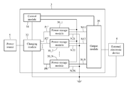
- FIG. 1 is a block diagram of a rechargeable battery according to an embodiment of the disclosure.
- the disclosure provides a rechargeable battery 1 , and the rechargeable battery 1 includes power storage modules 10 _ 1 ⁇ 10 _N, a charging module 12 and a control module 14 , wherein N is a positive integer larger than 1.
- the charging module 12 is electrically connected to the power storage modules 10 _ 1 ⁇ 10 _N.
- the control module 14 is electrically connected to the charging module 12 and the power storage modules 10 _ 1 ⁇ 10 _N.
- the power storage modules 10 _ 1 ⁇ 10 _N are used to store electricity.
- the battery 1 When the battery 1 is electrically connected to an external electronic device (not shown in FIG. 1 ) whose specification conforms to the specification of the battery 1 , the battery 1 , via the power storage modules 10 _ 1 ⁇ 10 _N, powers the external electronic device.
- the disclosure is not limited to the specification of each power storage module, such as the model, battery capacity or output voltage.
- each of the power storage modules 10 _ 1 ⁇ 10 _N includes a processing unit and a communication unit.
- the processing unit determines the states of charge of the power storage modules 10 _ 1 ⁇ 10 _N, and the communication unit sends the determinations to devices or modules except the power storage modules 10 _ 1 ⁇ 10 _N for relevant analysis and processing.
- the processing unit and the communication unit are, for example, respective integrated circuits (ICs) or integrated into the same IC.
- the communication unit wirelessly or wiredly sends the relevant data to devices or modules except the power storage modules 10 _ 1 ⁇ 10 _N.
- the charging module 12 is used to selectively charge one or more of the power storage modules 10 _ 1 ⁇ 10 _N through the charging paths P 1 ⁇ PN.
- the power storage modules 10 _ 1 ⁇ 10 _N respectively correspond to different charging paths P 1 ⁇ PN.
- the power storage module 10 _ 1 corresponds to the charging path P 1
- the power storage module 10 _ 2 corresponds to the charging path P 2
- the others can be deduced by analogy and will not be described hereinafter.
- the charging path P 1 is different from the charging path P 2 .
- the charging module 12 has different charging ports that are electrically connected to the power storage modules 10 _ 1 ⁇ 10 _N one to one, so as to prevent the charging paths P 1 ⁇ PN from being electrically connected to each other.
- the control module 14 is used to command the charging module 12 to charge at least one of the power storage modules 10 _ 1 ⁇ 10 _N according to the SoC indicator of the power storage modules 10 _ 1 ⁇ 10 _N.
- the control module 14 commands the charging module 12 to charge one or more power storage modules with the lowest SoC among the power storage modules 10 _ 1 ⁇ 10 _N.
- the control module 14 according to the SoC of each of the power storage modules 10 _ 1 ⁇ 10 _N, searches out which power storage module has the lowest SoC among the power storage modules 10 _ 1 ⁇ 10 _N.
- the control module 14 searches out which one of the power storage modules has the lowest SoC according to the SoC of one or more typical power storage modules among the power storage modules 10 _ 1 ⁇ 10 _N. In other words, in this embodiment, the control module 14 determines the SoC of M power storage modules among the power storage modules 10 _ 1 ⁇ 10 _N, and M is a positive integer larger than 1 but smaller than or equal to N.
- the control module 14 is a micro control unit (MCU).
- control module 14 determines the states of charge of all of the power storage modules 10 _ 1 ⁇ 10 _N
- the disclosure neither is limited to the amount of power storage modules used by the control module 14 to search out one or more power storage modules with the lowest SoC, nor is limited to the manner used by the control module 14 to determine and calculate the SoC.
- a user electrically connects the rechargeable battery 1 to the power source 5 for charging the battery 1 .
- a power source 5 is supply mains.
- the electric connection manner between the battery 1 and the power source 5 and the type of the power source 5 are not limited herein. It is assumed that the power storage module 10 _ 1 has the lowest SoC, and in this case, the control module 14 commands the charging module 12 according to the above determination to use the electricity provided by the power source 5 to charge the power storage module 10 _ 1 .
- the control module 14 searches at least one present power storage module with the lowest SoC and a new SoC threshold for the repeat of the foregoing charging process.
- the above searching process at the first time can be done before or after the battery 1 is connected to the power source 5 .
- the SoC threshold is, for example, the second lowest SoC among the power storage modules 10 _ 1 ⁇ 10 _N. Assume that the power storage module 10 _ 2 has the second lowest SoC, and when the control module 14 learns about that the SoC of the power storage module 10 _ 1 is charged to be similar to the SoC of the power storage module 10 _ 2 , the control module 14 would further command the charging module 12 to simultaneously charge the power storage module 10 _ 1 and the power storage module 10 _ 2 .
- the so-called similar SoC is that the difference between the SoC of the power storage module 10 _ 1 and the SoC of the power storage module 10 _ 2 is substantially equal to or less than a preset threshold.
- the SoC of the power storage module 10 _ 1 herein is smaller than, substantially equal to or larger than the SoC of the power storage module 10 _ 2 .
- the preset threshold can freely be designed according to a variety of practical requirements by a person of ordinary skill in the art, and the disclosure has no limitation thereon.
- the control module 14 can circularly and repeatedly search for one or more power storage modules with the lowest SoC among the power storage modules 10 _ 1 ⁇ 10 _N, and the one or more power storage modules with the lowest SoC are subjected to the above charging process.
- the present power storage module with the lowest SoC is defined as, for example, a first power storage module
- the present power storage module is defined as, for example, a second power storage module
- the control module uses the SoC of the second power storage module as a present SoC threshold.
- the present second power storage module is redefined as another first power storage module, so the amount of present first power storage modules increases.
- the control module 14 further selects one or more power storage modules among the power storage modules 10 _ 1 ⁇ 10 _N except the present first power storage modules to define the one or more selected power storage modules as one or more new second power storage modules, and then sets the SoC of the one or more new second power storage modules as a new SoC threshold, and the one or more present first power storage modules, the one or more present second power storage modules and the present SoC threshold are subjected to the above steps.
- the control module 14 when the amount of first power storage modules is up to a preset value, the control module 14 will directly charge all the power storage modules together instead of repeating the above circular process.
- control module 14 when a ratio of the amount of first power storage modules to the amount of all power storage modules is up to a preset ratio, the control module 14 will directly charge all the power storage modules together instead of repeating the above circular process. Therefore, it may be assured that at least a part of power storage modules in the battery 1 has similar states of charge, so as to prevent that a certain power storage module always has the lowest SoC.
- FIG. 2 is a block diagram of a rechargeable battery according to another embodiment of the disclosure.
- a charging module 22 in a battery 2 in the embodiment in FIG. 2 includes charging units 222 _ 1 ⁇ 222 _N.
- the charging units 222 _ 1 ⁇ 222 _N are electrically connected to power storage modules 20 _ 1 ⁇ 20 _N, respectively.
- the charging unit 222 _ 1 is electrically connected to the power storage module 20 _ 1
- the charging unit 222 _ 2 is electrically connected to the power storage module 20 _ 2 , and the others can be deduced by analogy and will not be described herein.
- the charging units 222 _ 1 ⁇ 222 _N are used to selectively charge the power storage modules 20 _ 1 ⁇ 20 _N through charging paths P 1 ′ ⁇ PN′. Each of the charging units 222 _ 1 ⁇ 222 _N corresponds to one of the charging paths P 1 ′ ⁇ PN′.
- the charging unit 222 _ 1 is used to charge the power storage module 20 _ 1 through the charging path P 1 ′
- the charging unit 222 _ 2 is used to charge the power storage module 20 _ 2 through the charging path P 2 ′, and the others can be deduced by analogy and will not be described hereafter.
- the charging units 222 _ 1 ⁇ 222 _N are not limited to be the same or different.
- the control module 24 commands at least one of the charging units 222 _ 1 ⁇ 222 _N to charge the power storage modules 20 _ 1 ⁇ 20 _N electrically connected thereto according to the states of charge of the power storage modules 20 _ 1 ⁇ 20 _N. Specifically, the control module 24 searches out at least one power storage module with the lowest SoC among the power storage modules 20 _ 1 ⁇ 20 _N and commands at least one charging unit corresponding to the at least one power storage module with the lowest SoC to charge the at least one power storage module with the lowest SoC.
- the searching manner can be referred to the explanation of the control module 14 , and however, a slight difference between the control module 14 and the control module 24 is that the control module 24 commands at least one of the charging units 222 _ 1 ⁇ 222 _N according to the states of charge of the power storage modules 20 _ 1 ⁇ 20 _N to charge at least one of the power storage modules 20 _ 1 ⁇ 20 _N respectively electrically connected to the charging units 222 _ 1 ⁇ 222 _N.
- FIG. 3 is a block diagram of a rechargeable battery according to yet another embodiment of the disclosure.
- a battery 3 in the embodiment in FIG. 3 further includes an output module 36 that is electrically connected to electricity storage units 30 _ 1 ⁇ 30 _N.
- the electricity storage units 30 _ 1 ⁇ 30 _N power the external electronic device 4 through the output module 36 .
- the electricity storage units 30 _ 1 ⁇ 30 _N are connected to the same ground end, and the output module 36 includes a bus for selectively electrically connected to the electricity storage units 30 _ 1 ⁇ 30 _N.
- each of the electricity storage units 30 _ 1 ⁇ 30 _N has, for example, a first transmission end and a second transmission end to transmit DC power, and the first transmission end and the second transmission end are, for example, the positive and negative ends of the DC power source. More particularly, the electricity storage unit 30 _ 1 has a first transmission end N 11 and a second transmission end N 21 , the electricity storage unit 30 _ 2 has a first transmission end N 12 and a second transmission end N 22 , and the others can be deduced by analogy and will not be described hereafter.
- the control module 34 commands the output module 36 to couple to at least a part of the first transmission ends of the electricity storage units 30 _ 1 ⁇ 30 _N through its bus, and the control module 34 also commands the charging module 32 not to charge the electricity storage units 30 _ 1 ⁇ 30 _N.
- the second transmission ends of the electricity storage units 30 _ 1 ⁇ 30 _N are coupled to the same ground end so that at least a part of the electricity storage units 30 _ 1 ⁇ 30 _N is connected in parallel.
- the battery 3 powers the external electronic device 4 via the parallel-connected electricity storage units.
- the control module 34 commands the output module 36 not to couple to the first transmission ends of the electricity storage units 30 _ 1 ⁇ 30 _N via the bus, so the electricity storage units 30 _ 1 ⁇ 30 _N as described above are charged through different current paths.
- the first transmission ends N 11 ⁇ N 1 N are coupled to the charging paths P 1 ⁇ PN, respectively.
- the charging path P 1 is coupled to the first transmission end N 11
- the charging path P 2 is coupled to the first transmission end N 12
- the others can be deduced by analogy and no more description hereafter.
- control module 34 can be electrically connected to the external electronic device 4 .
- control module 34 can further provide the information about the power storage modules 30 _ 1 ⁇ 30 _N to the external electronic device 4 .
- the information about the power storage module is, for example, the specification, current SoC or other information of the power storage module. It is optional for the control module 34 to provide the external electronic device 4 with information, and the disclosure is not limited thereto.
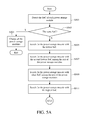
- FIG. 4 is a flow chart of a charging method according to an embodiment of the disclosure.
- step S 401 the SoC of each of the power storage modules is obtained.
- step S 403 one of charging paths is used to charge at least one of the power storage modules according to the SoC of each of the power storage modules.
- Each of the power storage modules corresponds to different one of the charging paths.
- obtaining the SoC of each power storage module includes searching out at least one first power storage module with the lowest SoC among the power storage modules and charging the at least one first power storage module.
- the charging method further includes searching out at least one second power storage module with the second lowest SoC among the power storage modules.
- the SoC of the at least one first power storage module is charged to be not smaller than a SoC threshold, the at least one first power storage module and the at least one second power storage module are charged.
- the SoC threshold is, for example, substantially equal to the SoC of at least one second power storage module.
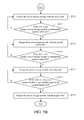
- FIGS. 1, 5A and 5B are flow charts of a charging method according to another embodiment of the disclosure.
- this embodiment assumes that N is 5 and the states of charge of the power storage modules 10 _ 1 ⁇ 10 _ 5 are different from each other; and for example, in the beginning, the SoC of the power storage module 10 _ 1 is the lowest, the SoC of the power storage module 10 _ 2 is the second lowest, the states of charge of the power storage modules 10 _ 3 and 10 _ 4 are higher than the SoC of the power storage module 10 _ 2 , and the SoC of the power storage module 10 _ 5 is the highest.
- step S 501 the states of charge of the power storage modules 10 _ 1 ⁇ 10 _ 5 are detected in step S 501 .
- step S 503 it is done to determine whether the states of charge of the power storage modules 10 _ 1 ⁇ 10 _ 5 are the same. If yes, the process proceeds to step S 504 , where the power storage modules 10 _ 1 ⁇ 10 _ 5 are charged until charging all the power storage modules 10 _ 1 ⁇ 10 _ 5 is complete or the power source 5 is removed. If not, the process proceeds to step S 505 , to search for the power storage module with the lowest SoC, i.e. the power storage module 10 _ 1 .
- step S 507 the power storage module with the second lowest SoC, i.e. the power storage module 10 _ 2 , is found among the power storage modules except the power storage module 10 _ 1 .
- step S 509 one or more power storage modules of other one or more states of charge are found among the power storage modules except the power storage modules 10 _ 1 and 10 _ 2 .
- the other one or more states of charge are, for example, one or more states of charge higher than the second lowest SoC but lower than the highest SoC, and the power storage modules of other one or more states of charge are, for example, the power storage modules 10 _ 3 and 10 _ 4 .
- the SoC of the power storage module 10 _ 3 and the SoC of the power storage module 10 _ 4 are sorted, and it can be learn that the SoC of the power storage module 10 _ 3 is lower than the SoC of the power storage module 10 _ 4 .
- step S 511 the power storage module with the highest SoC, i.e. the power storage module 10 _ 5 , is searched out.
- step S 513 the power storage module with the lowest SoC, i.e. the power storage module 10 _ 1 in this embodiment, is charged.
- step S 515 it is done to determine whether the SoC of the charged power storage module is substantially equal to the original second lowest SoC, i.e. the SoC of the power storage module 10 _ 2 in the beginning.
- step S 513 will be repeated to charge the power storage module 10 _ 1 until the SoC of the power storage module 10 _ 1 is substantially equal to the original second SoC, so the states of charge of the power storage modules 10 _ 1 and 10 _ 2 are the lowest herein; and if yes, the process proceeds to step S 517 to charge one or more present storage modules with the lowest SoC, i.e. the power storage modules 10 _ 1 and 10 _ 2 , together.
- step S 519 it is done to determine whether the present states of charge of the power storage modules 10 _ 1 and 10 _ 2 are substantially equal to the original SoC of at least one of the power storage modules 10 _ 3 and 10 _ 4 . If not, step S 517 is repeated to keep charging the power storage modules 10 _ 1 and 10 _ 2 . If yes, the process proceeds to step S 521 to charge the power storage modules 10 _ 1 to 10 _ 4 together.
- the states of charge of the power storage modules 10 _ 1 , 10 _ 2 and 10 _ 3 are charged to a SoC similar to the SoC of the power storage module 10 _ 4 after the SoCs of the power storage modules 10 _ 1 and 10 _ 2 are charged to be a SoC similar to the SoC of the power storage module 10 _ 3 .
- the process proceeds to step S 523 to determine whether the SoC of each power storage module is substantially equal to the original highest SoC, i.e. the SoC of the power storage module 10 _ 5 in the beginning.
- step S 521 is repeated to charge the power storage modules 10 _ 1 to 10 _ 4 . If yes, the process proceeds to step S 525 to charge one or more present power storage modules with the highest SoC, i.e. all the power storage modules 10 _ 1 to 10 _ 5 .
- the disclosure provides a rechargeable battery and a charging method thereof, to determine the SoC of each of power storage modules and then charge at least one of the power storage modules, which has the lowest SoC.
- a first power storage module with the lowest SoC is charged to have a SoC similar to a second power storage module with the second lowest SoC
- the first power storage module and the second power storage module are charged together. Therefore, it may be assured that there is more than one power storage module having a similar SoC before the charging process ends, so as to prevent the same power storage module from always having the lowest SoC.
- the rechargeable battery and the charging method thereof in the disclosure may consider each power storage module to avoid always charging the same power storage module by a high current, so as to maintain the inherent lifespan of a battery. Therefore, the disclosure may have relatively high practicability.
Landscapes
- Engineering & Computer Science (AREA)
- Power Engineering (AREA)
- Manufacturing & Machinery (AREA)
- Chemical & Material Sciences (AREA)
- Chemical Kinetics & Catalysis (AREA)
- Electrochemistry (AREA)
- General Chemical & Material Sciences (AREA)
- Charge And Discharge Circuits For Batteries Or The Like (AREA)
- Secondary Cells (AREA)
Abstract
A rechargeable battery includes power storage modules, a charging module and a control module. The charging module is electrically connected to the power storage modules. The control module is electrically connected to the power storage modules. The charging module is configured to selectively charge the power storage modules through a plurality of charging paths. Each power storage module corresponds to one of the charging paths. The control module is configured to command the charging module to charge at least one of the power storage modules according to the SoC of each power storage module.
Description
- This non-provisional application claims priority under 35 U.S.C. §119(a) on Patent Application No(s). 105116837 filed in Taiwan, R.O.C. on May 30, 2016, the entire contents of which are hereby incorporated by reference.
- The disclosure is related to a rechargeable battery and a charging method thereof, more particularly to a rechargeable battery with multiple power storage modules and a charging method thereof.
- The battery or battery pack in a modern electronic product usually has multiple power storage modules for the enhancement of battery power supply capacity or battery lifetime. However, in fact, power storage modules in a battery may at least in part have different power supply capacities, so these power storage modules may at least in part have different states of charge at the same time point. In the duration of charging a battery or a battery pack, all the storage modules are subjected to the same charging mode or manner while not every storage module's real state would be considered. Because of non-ideal facts in practice or the user's habit, the battery or battery pack may not be fully charged. Certain one of the storage modules may always be the lowest due to the different states of charge of the storage modules, so this storage module is usually charged with a current of high potential. Therefore, the lifespan of the battery or battery pack would be shortened, and even a danger may occur easily.
- According to one or more embodiments, a rechargeable battery includes power storage modules, a charging module and a control module. The charging module is electrically connected to the power storage modules, and the control module is electrically connected to the charging module and the power storage modules. The charging module selectively charges the power storage modules through charging paths, each of which corresponds to one of the power storage modules. The control module commands the charging module to charge at least one of the power storage modules according to the state of charge (SoC) indicator of each of the power storage modules.
- According to one or more embodiments of the disclosure, a charging method includes the following steps. First, the SoC of each of the power storage modules is acquired. Then, at least one of the power storage modules is charged through one of charging paths according to the SoC of each of the power storage modules. Each of the power storage modules corresponds to different one of the charging paths.
- The present disclosure will become more fully understood from the detailed description given hereinbelow and the accompanying drawings which are given by way of illustration only and thus are not limitative of the present disclosure and wherein:
-
FIG. 1 is a block diagram of a rechargeable battery according to an embodiment of the disclosure; -
FIG. 2 is a block diagram of a rechargeable battery according to another embodiment of the disclosure; -
FIG. 3 is a block diagram of a rechargeable battery according to yet another embodiment of the disclosure; -
FIG. 4 is a flow chart of a charging method according to an embodiment of the disclosure; and -
FIG. 5A andFIG. 5B are flow charts of a charging method according to another embodiment of the disclosure. - In the following detailed description, for purposes of explanation, numerous specific details are set forth in order to provide a thorough understanding of the disclosed embodiments. It will be apparent, however, that one or more embodiments may be practiced without these specific details. In other instances, well-known structures and devices are schematically shown in order to simplify the drawing.
- Please refer to
FIG. 1 .FIG. 1 is a block diagram of a rechargeable battery according to an embodiment of the disclosure. The disclosure provides arechargeable battery 1, and therechargeable battery 1 includes power storage modules 10_1˜10_N, acharging module 12 and acontrol module 14, wherein N is a positive integer larger than 1. Thecharging module 12 is electrically connected to the power storage modules 10_1˜10_N. Thecontrol module 14 is electrically connected to thecharging module 12 and the power storage modules 10_1˜10_N. - The power storage modules 10_1˜10_N are used to store electricity. When the
battery 1 is electrically connected to an external electronic device (not shown inFIG. 1 ) whose specification conforms to the specification of thebattery 1, thebattery 1, via the power storage modules 10_1˜10_N, powers the external electronic device. Herein the disclosure is not limited to the specification of each power storage module, such as the model, battery capacity or output voltage. In an embodiment, each of the power storage modules 10_1˜10_N includes a processing unit and a communication unit. The processing unit determines the states of charge of the power storage modules 10_1˜10_N, and the communication unit sends the determinations to devices or modules except the power storage modules 10_1˜10_N for relevant analysis and processing. The processing unit and the communication unit are, for example, respective integrated circuits (ICs) or integrated into the same IC. For example, the communication unit wirelessly or wiredly sends the relevant data to devices or modules except the power storage modules 10_1˜10_N. The above description is only for exemplary implementations, and the disclosure is not limited to these exemplary implementations. - The
charging module 12 is used to selectively charge one or more of the power storage modules 10_1˜10_N through the charging paths P1˜PN. The power storage modules 10_1˜10_N respectively correspond to different charging paths P1˜PN. Specifically, the power storage module 10_1 corresponds to the charging path P1, the power storage module 10_2 corresponds to the charging path P2, and the others can be deduced by analogy and will not be described hereinafter. The charging path P1 is different from the charging path P2. In an embodiment, thecharging module 12 has different charging ports that are electrically connected to the power storage modules 10_1˜10_N one to one, so as to prevent the charging paths P1˜PN from being electrically connected to each other. - The
control module 14 is used to command thecharging module 12 to charge at least one of the power storage modules 10_1˜10_N according to the SoC indicator of the power storage modules 10_1˜10_N. In an embodiment, thecontrol module 14 commands thecharging module 12 to charge one or more power storage modules with the lowest SoC among the power storage modules 10_1˜10_N. In details, for example, thecontrol module 14, according to the SoC of each of the power storage modules 10_1˜10_N, searches out which power storage module has the lowest SoC among the power storage modules 10_1˜10_N. In another embodiment, for example, thecontrol module 14 searches out which one of the power storage modules has the lowest SoC according to the SoC of one or more typical power storage modules among the power storage modules 10_1˜10_N. In other words, in this embodiment, thecontrol module 14 determines the SoC of M power storage modules among the power storage modules 10_1˜10_N, and M is a positive integer larger than 1 but smaller than or equal to N. For example, thecontrol module 14 is a micro control unit (MCU). Although the following description is based on that thecontrol module 14 determines the states of charge of all of the power storage modules 10_1˜10_N, the disclosure neither is limited to the amount of power storage modules used by thecontrol module 14 to search out one or more power storage modules with the lowest SoC, nor is limited to the manner used by thecontrol module 14 to determine and calculate the SoC. - In an operational situation of charging the
rechargeable battery 1, a user electrically connects therechargeable battery 1 to thepower source 5 for charging thebattery 1. For example, such apower source 5 is supply mains. Herein, the electric connection manner between thebattery 1 and thepower source 5 and the type of thepower source 5 are not limited herein. It is assumed that the power storage module 10_1 has the lowest SoC, and in this case, thecontrol module 14 commands thecharging module 12 according to the above determination to use the electricity provided by thepower source 5 to charge the power storage module 10_1. When the SoC of the power storage module 10_1 is charged up to a SoC threshold, thecontrol module 14 searches at least one present power storage module with the lowest SoC and a new SoC threshold for the repeat of the foregoing charging process. The above searching process at the first time can be done before or after thebattery 1 is connected to thepower source 5. - In an embodiment, the SoC threshold is, for example, the second lowest SoC among the power storage modules 10_1˜10_N. Assume that the power storage module 10_2 has the second lowest SoC, and when the
control module 14 learns about that the SoC of the power storage module 10_1 is charged to be similar to the SoC of the power storage module 10_2, thecontrol module 14 would further command the chargingmodule 12 to simultaneously charge the power storage module 10_1 and the power storage module 10_2. The so-called similar SoC is that the difference between the SoC of the power storage module 10_1 and the SoC of the power storage module 10_2 is substantially equal to or less than a preset threshold. In other words, the SoC of the power storage module 10_1 herein is smaller than, substantially equal to or larger than the SoC of the power storage module 10_2. The preset threshold can freely be designed according to a variety of practical requirements by a person of ordinary skill in the art, and the disclosure has no limitation thereon. - In practice, the
control module 14 can circularly and repeatedly search for one or more power storage modules with the lowest SoC among the power storage modules 10_1˜10_N, and the one or more power storage modules with the lowest SoC are subjected to the above charging process. Particularly, the present power storage module with the lowest SoC is defined as, for example, a first power storage module, and the present power storage module is defined as, for example, a second power storage module, and the control module uses the SoC of the second power storage module as a present SoC threshold. When the SoC of the first power storage module is charged to a SoC similar to the present SoC threshold, the present second power storage module is redefined as another first power storage module, so the amount of present first power storage modules increases. Thecontrol module 14 further selects one or more power storage modules among the power storage modules 10_1˜10_N except the present first power storage modules to define the one or more selected power storage modules as one or more new second power storage modules, and then sets the SoC of the one or more new second power storage modules as a new SoC threshold, and the one or more present first power storage modules, the one or more present second power storage modules and the present SoC threshold are subjected to the above steps. In an embodiment, when the amount of first power storage modules is up to a preset value, thecontrol module 14 will directly charge all the power storage modules together instead of repeating the above circular process. In another embodiment, when a ratio of the amount of first power storage modules to the amount of all power storage modules is up to a preset ratio, thecontrol module 14 will directly charge all the power storage modules together instead of repeating the above circular process. Therefore, it may be assured that at least a part of power storage modules in thebattery 1 has similar states of charge, so as to prevent that a certain power storage module always has the lowest SoC. - Please refer to
FIG. 2 .FIG. 2 is a block diagram of a rechargeable battery according to another embodiment of the disclosure. Different from the embodiment inFIG. 1 , a charging module 22 in abattery 2 in the embodiment inFIG. 2 includes charging units 222_1˜222_N. The charging units 222_1˜222_N are electrically connected to power storage modules 20_1˜20_N, respectively. Particularly, the charging unit 222_1 is electrically connected to the power storage module 20_1, the charging unit 222_2 is electrically connected to the power storage module 20_2, and the others can be deduced by analogy and will not be described herein. The charging units 222_1˜222_N are used to selectively charge the power storage modules 20_1˜20_N through charging paths P1′˜PN′. Each of the charging units 222_1˜222_N corresponds to one of the charging paths P1′˜PN′. In this embodiment, the charging unit 222_1 is used to charge the power storage module 20_1 through the charging path P1′, the charging unit 222_2 is used to charge the power storage module 20_2 through the charging path P2′, and the others can be deduced by analogy and will not be described hereafter. The charging units 222_1˜222_N are not limited to be the same or different. - The
control module 24 commands at least one of the charging units 222_1˜222_N to charge the power storage modules 20_1˜20_N electrically connected thereto according to the states of charge of the power storage modules 20_1˜20_N. Specifically, thecontrol module 24 searches out at least one power storage module with the lowest SoC among the power storage modules 20_1˜20_N and commands at least one charging unit corresponding to the at least one power storage module with the lowest SoC to charge the at least one power storage module with the lowest SoC. The searching manner can be referred to the explanation of thecontrol module 14, and however, a slight difference between thecontrol module 14 and thecontrol module 24 is that thecontrol module 24 commands at least one of the charging units 222_1˜222_N according to the states of charge of the power storage modules 20_1˜20_N to charge at least one of the power storage modules 20_1˜20_N respectively electrically connected to the charging units 222_1˜222_N. - Please refer to
FIG. 3 .FIG. 3 is a block diagram of a rechargeable battery according to yet another embodiment of the disclosure. Different from the embodiment inFIG. 1 , abattery 3 in the embodiment inFIG. 3 further includes anoutput module 36 that is electrically connected to electricity storage units 30_1˜30_N. When thebattery 3 is electrically connected to an externalelectronic device 4, the electricity storage units 30_1˜30_N power the externalelectronic device 4 through theoutput module 36. In this embodiment, the electricity storage units 30_1˜30_N are connected to the same ground end, and theoutput module 36 includes a bus for selectively electrically connected to the electricity storage units 30_1˜30_N. - Specifically, each of the electricity storage units 30_1˜30_N has, for example, a first transmission end and a second transmission end to transmit DC power, and the first transmission end and the second transmission end are, for example, the positive and negative ends of the DC power source. More particularly, the electricity storage unit 30_1 has a first transmission end N11 and a second transmission end N21, the electricity storage unit 30_2 has a first transmission end N12 and a second transmission end N22, and the others can be deduced by analogy and will not be described hereafter. When the
battery 3 is electrically connected to the externalelectronic device 4 to power the externalelectronic device 4, thecontrol module 34 commands theoutput module 36 to couple to at least a part of the first transmission ends of the electricity storage units 30_1˜30_N through its bus, and thecontrol module 34 also commands the chargingmodule 32 not to charge the electricity storage units 30_1˜30_N. In this embodiment, the second transmission ends of the electricity storage units 30_1˜30_N are coupled to the same ground end so that at least a part of the electricity storage units 30_1˜30_N is connected in parallel. Thebattery 3 powers the externalelectronic device 4 via the parallel-connected electricity storage units. When thebattery 3 is charged by thepower source 5, thecontrol module 34 commands theoutput module 36 not to couple to the first transmission ends of the electricity storage units 30_1˜30_N via the bus, so the electricity storage units 30_1˜30_N as described above are charged through different current paths. In an embodiment, for the power storage modules 30_1˜30_N, the first transmission ends N11˜N1N are coupled to the charging paths P1˜PN, respectively. Particularly, the charging path P1 is coupled to the first transmission end N11, the charging path P2 is coupled to the first transmission end N12, and the others can be deduced by analogy and no more description hereafter. - In addition, in the embodiment in
FIG. 3 , thecontrol module 34 can be electrically connected to the externalelectronic device 4. Also, thecontrol module 34 can further provide the information about the power storage modules 30_1˜30_N to the externalelectronic device 4. The information about the power storage module is, for example, the specification, current SoC or other information of the power storage module. It is optional for thecontrol module 34 to provide the externalelectronic device 4 with information, and the disclosure is not limited thereto. - Based on the above concept, the disclosure further provides a charging method. Please refer to
FIG. 4 to explain the charging method.FIG. 4 is a flow chart of a charging method according to an embodiment of the disclosure. In step S401, the SoC of each of the power storage modules is obtained. In step S403, one of charging paths is used to charge at least one of the power storage modules according to the SoC of each of the power storage modules. Each of the power storage modules corresponds to different one of the charging paths. In an embodiment, obtaining the SoC of each power storage module includes searching out at least one first power storage module with the lowest SoC among the power storage modules and charging the at least one first power storage module. In another embodiment, the charging method further includes searching out at least one second power storage module with the second lowest SoC among the power storage modules. When the SoC of the at least one first power storage module is charged to be not smaller than a SoC threshold, the at least one first power storage module and the at least one second power storage module are charged. The SoC threshold is, for example, substantially equal to the SoC of at least one second power storage module. - Please refer to
FIGS. 1, 5A and 5B to illustrate a particular embodiment of the disclosure.FIG. 5A andFIG. 5B are flow charts of a charging method according to another embodiment of the disclosure. For a concise description, this embodiment assumes that N is 5 and the states of charge of the power storage modules 10_1˜10_5 are different from each other; and for example, in the beginning, the SoC of the power storage module 10_1 is the lowest, the SoC of the power storage module 10_2 is the second lowest, the states of charge of the power storage modules 10_3 and 10_4 are higher than the SoC of the power storage module 10_2, and the SoC of the power storage module 10_5 is the highest. - In the embodiment shown in
FIG. 5A andFIG. 5B , the states of charge of the power storage modules 10_1˜10_5 are detected in step S501. In step S503, it is done to determine whether the states of charge of the power storage modules 10_1˜10_5 are the same. If yes, the process proceeds to step S504, where the power storage modules 10_1˜10_5 are charged until charging all the power storage modules 10_1˜10_5 is complete or thepower source 5 is removed. If not, the process proceeds to step S505, to search for the power storage module with the lowest SoC, i.e. the power storage module 10_1. Then, in step S507, the power storage module with the second lowest SoC, i.e. the power storage module 10_2, is found among the power storage modules except the power storage module 10_1. Also, in step S509, one or more power storage modules of other one or more states of charge are found among the power storage modules except the power storage modules 10_1 and 10_2. In this embodiment, the other one or more states of charge are, for example, one or more states of charge higher than the second lowest SoC but lower than the highest SoC, and the power storage modules of other one or more states of charge are, for example, the power storage modules 10_3 and 10_4. In another embodiment, the SoC of the power storage module 10_3 and the SoC of the power storage module 10_4 are sorted, and it can be learn that the SoC of the power storage module 10_3 is lower than the SoC of the power storage module 10_4. In step S511, the power storage module with the highest SoC, i.e. the power storage module 10_5, is searched out. - Then, in step S513, the power storage module with the lowest SoC, i.e. the power storage module 10_1 in this embodiment, is charged. In step S515, it is done to determine whether the SoC of the charged power storage module is substantially equal to the original second lowest SoC, i.e. the SoC of the power storage module 10_2 in the beginning. If not, step S513 will be repeated to charge the power storage module 10_1 until the SoC of the power storage module 10_1 is substantially equal to the original second SoC, so the states of charge of the power storage modules 10_1 and 10_2 are the lowest herein; and if yes, the process proceeds to step S517 to charge one or more present storage modules with the lowest SoC, i.e. the power storage modules 10_1 and 10_2, together.
- In step S519, it is done to determine whether the present states of charge of the power storage modules 10_1 and 10_2 are substantially equal to the original SoC of at least one of the power storage modules 10_3 and 10_4. If not, step S517 is repeated to keep charging the power storage modules 10_1 and 10_2. If yes, the process proceeds to step S521 to charge the power storage modules 10_1 to 10_4 together. In the embodiment where the SoC of the power storage module 10_3 and the SoC of the power storage module 10_4 are sorted, the states of charge of the power storage modules 10_1, 10_2 and 10_3 are charged to a SoC similar to the SoC of the power storage module 10_4 after the SoCs of the power storage modules 10_1 and 10_2 are charged to be a SoC similar to the SoC of the power storage module 10_3. After step S521, the process proceeds to step S523 to determine whether the SoC of each power storage module is substantially equal to the original highest SoC, i.e. the SoC of the power storage module 10_5 in the beginning. If not, step S521 is repeated to charge the power storage modules 10_1 to 10_4. If yes, the process proceeds to step S525 to charge one or more present power storage modules with the highest SoC, i.e. all the power storage modules 10_1 to 10_5.
- In summary, the disclosure provides a rechargeable battery and a charging method thereof, to determine the SoC of each of power storage modules and then charge at least one of the power storage modules, which has the lowest SoC. In a manner, when a first power storage module with the lowest SoC is charged to have a SoC similar to a second power storage module with the second lowest SoC, the first power storage module and the second power storage module are charged together. Therefore, it may be assured that there is more than one power storage module having a similar SoC before the charging process ends, so as to prevent the same power storage module from always having the lowest SoC. The rechargeable battery and the charging method thereof in the disclosure may consider each power storage module to avoid always charging the same power storage module by a high current, so as to maintain the inherent lifespan of a battery. Therefore, the disclosure may have relatively high practicability.
Claims (10)
1. A rechargeable battery, comprising:
power storage modules;
a charging module electrically connected to the power storage modules and configured to selectively charge the power storage modules through charging paths, each of which corresponds to one of the power storage modules, when electrically connected to a power source; and
a control module electrically connected to the charging module and the power storage modules and configured to command the charging module to charge at least one of the power storage modules according to a state of charge (SoC) indicator of each of the power storage modules.
2. The battery according to claim 1 , wherein the control module commands the charging module to charge at least one of the power storage modules, which has the lowest SoC.
3. The battery according to claim 1 , wherein the charging module comprises charging units, each of which is electrically connected to one of the power storage modules and corresponds to one of the charging paths, the charging units are configured to selectively charge the power storage modules through one or more of the charging paths, and the control module commands at least one of the charging units to charge the power storage module electrically connected to the at least one charging unit according to the SoC indicators of the power storage modules.
4. The battery according to claim 3 , wherein the control module searches out at least one of the power storage modules, which has the lowest SoC, and commands at least related one of the charging units to charge the at least one power storage module with the lowest SoC.
5. The battery according to claim 1 , further comprising:
an output module electrically connected to the power storage modules, and the power storage modules powering an external electronic device through the output module when the battery is electrically connected to the external electronic device.
6. The battery according to claim 5 , wherein when the power storage modules power the external electronic device through the output module, the charging module stops charging the power storage modules.
7. A charging method for a battery that comprises power storage modules, and the charging method comprising:
acquiring a SoC of each of the power storage modules; and
charging at least one of the power storage modules through one of charging paths according to the SoC of each of the power storage modules;
wherein each of the power storage modules corresponds to different one of the charging paths.
8. The charging method according to claim 7 , wherein acquiring the SoC of each of the power storage modules comprises:
searching out at least one first power storage module with the lowest SoC among the power storage modules; and
charging the at least one first power storage module.
9. The charging method according to claim 8 , further comprising:
searching out at least one second power storage module with the second lowest SoC among the power storage modules; and
simultaneously charging the at least one first power storage module and the least one second power storage module when the SoC of the at least one first power storage module is charged up to not smaller than a SoC threshold.
10. The charging method according to claim 9 , wherein the SoC threshold is the SoC of the least one second power storage module.
Applications Claiming Priority (2)
| Application Number | Priority Date | Filing Date | Title |
|---|---|---|---|
| TW105116837 | 2016-05-30 | ||
| TW105116837A TW201742350A (en) | 2016-05-30 | 2016-05-30 | Rechargeable battery and charging method thereof |
Publications (1)
| Publication Number | Publication Date |
|---|---|
| US20170346309A1 true US20170346309A1 (en) | 2017-11-30 |
Family
ID=60418280
Family Applications (1)
| Application Number | Title | Priority Date | Filing Date |
|---|---|---|---|
| US15/239,478 Abandoned US20170346309A1 (en) | 2016-05-30 | 2016-08-17 | Rechargeable battery and charging method thereof |
Country Status (3)
| Country | Link |
|---|---|
| US (1) | US20170346309A1 (en) |
| CN (1) | CN107453417A (en) |
| TW (1) | TW201742350A (en) |
Citations (48)
| Publication number | Priority date | Publication date | Assignee | Title |
|---|---|---|---|---|
| US5003244A (en) * | 1989-05-09 | 1991-03-26 | Digital Equipment Corporation | Battery charger for charging a plurality of batteries |
| US6466024B1 (en) * | 1988-07-13 | 2002-10-15 | Electronic Development, Inc. | Multi-battery fuel saving and emission reduction system for automotive vehicles |
| US6803745B2 (en) * | 2002-02-07 | 2004-10-12 | Ricoh Company, Ltd. | Battery pack charging apparatus and method |
| US20060029846A1 (en) * | 2004-08-06 | 2006-02-09 | Masaaki Konoto | Fuel cell system |
| US20060083955A1 (en) * | 2004-10-19 | 2006-04-20 | Akihiko Kanouda | Mobile type information terminal and self diagnosis method and operation method thereof |
| US20080136371A1 (en) * | 2006-12-06 | 2008-06-12 | Sehat Sutardja | Plug-in vehicle |
| US20080258677A1 (en) * | 2007-04-18 | 2008-10-23 | Powertech Industrial Co., Ltd. | Power supply for portable apparatuses |
| US20100019729A1 (en) * | 2008-07-25 | 2010-01-28 | Toyota Jidosha Kabushiki Kaisha | Power supply system and vehicle with the system |
| US20100131137A1 (en) * | 2007-06-15 | 2010-05-27 | Toyota Jidosha Kabushiki Kaisha | Power supply system, vehicle with the same and charge/discharge control method |
| US20110025126A1 (en) * | 2009-07-31 | 2011-02-03 | Ladislaus Joseph Brabec | Bi-directional battery voltage converter |
| US20110080139A1 (en) * | 2009-04-16 | 2011-04-07 | Russell Troxel | Batteries, Battery Systems, Battery Submodules, Battery Operational Methods, Battery System Operational Methods, Battery Charging Methods, and Battery System Charging Methods |
| US7933694B2 (en) * | 2008-10-21 | 2011-04-26 | Toyota Jidosha Kabushiki Kaisha | Power supply system and vehicle including the same, and method of controlling power supply system |
| US20110279085A1 (en) * | 2008-12-09 | 2011-11-17 | Kyushu Electric Power Co., Inc. | Voltage equalization device, method, program, and power storage system |
| US20120025744A1 (en) * | 2010-07-27 | 2012-02-02 | Jin-Wan Kim | Battery pack and eletrical transfer apparatus including same |
| US20120074909A1 (en) * | 2010-09-28 | 2012-03-29 | Kabushiki Kaisha Toshiba | Storage battery management system |
| US8169191B2 (en) * | 2008-02-25 | 2012-05-01 | Werthman Dean A | System for use in gathering or processing data in a healthcare facility having fleet of mobile workstations |
| US20120133333A1 (en) * | 2009-08-04 | 2012-05-31 | Yukiko Morioka | Energy system |
| US20120153717A1 (en) * | 2010-12-16 | 2012-06-21 | Denso Corporation | Power supply apparatus for vehicles |
| US20120161708A1 (en) * | 2010-12-22 | 2012-06-28 | Hitachi Vehicle Energy, Ltd. | Cell Control Device and Electricity Storage Device Incorporating the Same |
| US20120169291A1 (en) * | 2009-10-05 | 2012-07-05 | Ngk Insulators, Ltd. | Controller, controller network and control method |
| US20120176091A1 (en) * | 2009-10-05 | 2012-07-12 | Ngk Insulators, Inc. | Control apparatus, control apparatus network and control method |
| US20120176095A1 (en) * | 2010-10-15 | 2012-07-12 | Sanyo Electric Co., Ltd. | Electric power management system |
| US8345454B1 (en) * | 2009-11-21 | 2013-01-01 | The Boeing Company | Architecture and control method for dynamically conditioning multiple DC sources to driven an AC load |
| US8423210B2 (en) * | 2008-10-21 | 2013-04-16 | Toyota Jidosha Kabushiki Kaisha | Power supply system and vehicle including the same, and method of controlling power supply system |
| US20130106357A1 (en) * | 2011-10-31 | 2013-05-02 | Cobasys, Llc | Intelligent charging and discharging system for parallel configuration of series cells with semiconductor switching |
| US20130113417A1 (en) * | 2011-11-09 | 2013-05-09 | Sony Corporation | Charge control device and charge control method |
| US20130119932A1 (en) * | 2011-09-02 | 2013-05-16 | Mando Corporation | Battery charging apparatus |
| US20130154360A1 (en) * | 2010-08-24 | 2013-06-20 | Suzuki Motor Corporation | Electric-powered vehicle |
| US20130154554A1 (en) * | 2011-12-20 | 2013-06-20 | Sony Mobile Communications Japan, Inc. | Mobile device and charging apparatus |
| US20130285608A1 (en) * | 2011-01-06 | 2013-10-31 | Nec Corporation | Charging control device, charging control method, and program |
| US20140009120A1 (en) * | 2012-07-09 | 2014-01-09 | Samsung Electronics Co., Ltd. | Method for charging battery and an electronic device thereof |
| US20140035361A1 (en) * | 2011-01-12 | 2014-02-06 | Ralph Schmidt | Method for controlling a battery, and battery for carrying out the method |
| US20140035513A1 (en) * | 2012-08-03 | 2014-02-06 | Honda Motor Co., Ltd. | Smart charging system |
| US20140070760A1 (en) * | 2012-09-07 | 2014-03-13 | Kohler Co. | Power generation system that optimizes the power provided to charge batteries |
| US20140320062A1 (en) * | 2011-11-22 | 2014-10-30 | Panasonic Corporation | Vehicle management system |
| US20140361732A1 (en) * | 2012-02-28 | 2014-12-11 | Omron Corporation | Storage battery control device, storage battery control method, program, power storage system and power supply system |
| US8942075B2 (en) * | 2012-03-27 | 2015-01-27 | Nec Corporation | Battery management device, battery apparatus, disk array apparatus and battery management method |
| US20150155720A1 (en) * | 2013-11-29 | 2015-06-04 | Denso Corporation | Charge-discharge controller, system and method |
| US20150194827A1 (en) * | 2012-09-26 | 2015-07-09 | Fujitsu Limited | Information processing device including battery and charging method of battery |
| US20150249350A1 (en) * | 2012-11-19 | 2015-09-03 | Hitachi, Ltd. | Storage battery control device and storage battery control method |
| US9368991B2 (en) * | 2012-10-30 | 2016-06-14 | The Board Of Trustees Of The University Of Alabama | Distributed battery power electronics architecture and control |
| US20160264012A1 (en) * | 2015-03-11 | 2016-09-15 | Lsis Co., Ltd. | Vehicle charging device and method for protecting internal circuit of the same |
| US20170005506A1 (en) * | 2009-10-14 | 2017-01-05 | Ud Trucks Corporation | Power storage apparatus |
| US20170033573A1 (en) * | 2015-07-28 | 2017-02-02 | Lsis Co., Ltd. | Energy management system |
| US20170190257A1 (en) * | 2015-12-30 | 2017-07-06 | Thunder Power Hong Kong Ltd. | Smart charging system for electric vehicle battery packs |
| US20170282745A1 (en) * | 2016-03-30 | 2017-10-05 | Honda Motor Co.,Ltd. | Power supply apparatus, transport device including power supply apparatus, estimating method of estimating correlation information between charge rate and open-end voltage of electric storage section, and computer readable medium for estimating correlation information |
| US20170292990A1 (en) * | 2016-04-06 | 2017-10-12 | Honda Motor Co.,Ltd. | Power supply apparatus, transport device including power supply apparatus, determination method of determining state of sensor detecting current value, and computer readable medium for determining state |
| US20170324268A1 (en) * | 2014-10-21 | 2017-11-09 | Toshiba Mitsubishi-Electric Industrial Systems Corporation | Charge/discharge management device |
Family Cites Families (3)
| Publication number | Priority date | Publication date | Assignee | Title |
|---|---|---|---|---|
| JP3890168B2 (en) * | 1999-08-03 | 2007-03-07 | 株式会社東京アールアンドデー | Electric device and charging / discharging method of battery unit thereof |
| TWM404155U (en) * | 2010-08-16 | 2011-05-21 | Sunyen Co Ltd | Electricity charger of the electric car |
| CN104319837A (en) * | 2014-10-17 | 2015-01-28 | 东风电动车辆股份有限公司 | Battery pack structure of electric automobile and charging and discharging method of battery pack |
-
2016
- 2016-05-30 TW TW105116837A patent/TW201742350A/en unknown
- 2016-07-11 CN CN201610542157.6A patent/CN107453417A/en active Pending
- 2016-08-17 US US15/239,478 patent/US20170346309A1/en not_active Abandoned
Patent Citations (80)
| Publication number | Priority date | Publication date | Assignee | Title |
|---|---|---|---|---|
| US6466024B1 (en) * | 1988-07-13 | 2002-10-15 | Electronic Development, Inc. | Multi-battery fuel saving and emission reduction system for automotive vehicles |
| US5003244A (en) * | 1989-05-09 | 1991-03-26 | Digital Equipment Corporation | Battery charger for charging a plurality of batteries |
| US6803745B2 (en) * | 2002-02-07 | 2004-10-12 | Ricoh Company, Ltd. | Battery pack charging apparatus and method |
| US7782011B2 (en) * | 2002-02-07 | 2010-08-24 | Ricoh Company, Ltd. | Battery pack charging apparatus and method for constant current and constant voltage charging of multiple battery packs |
| US7767353B2 (en) * | 2004-08-06 | 2010-08-03 | Sanyo Electric Co., Ltd. | Fuel cell system |
| US20060029846A1 (en) * | 2004-08-06 | 2006-02-09 | Masaaki Konoto | Fuel cell system |
| US8012638B2 (en) * | 2004-08-06 | 2011-09-06 | Sanyo Electric Co. Ltd. | Fuel cell system |
| US20100266919A1 (en) * | 2004-08-06 | 2010-10-21 | Sanyo Electric Co., Ltd. | Fuel cell system |
| US20060083955A1 (en) * | 2004-10-19 | 2006-04-20 | Akihiko Kanouda | Mobile type information terminal and self diagnosis method and operation method thereof |
| US7626353B2 (en) * | 2004-10-19 | 2009-12-01 | Hitachi, Ltd. | Mobile type information terminal and self diagnosis method and operation method thereof |
| US20080136371A1 (en) * | 2006-12-06 | 2008-06-12 | Sehat Sutardja | Plug-in vehicle |
| US7855528B2 (en) * | 2007-04-18 | 2010-12-21 | Powertech Industrial Co., Ltd. | Power supply for portable apparatuses |
| US20080258677A1 (en) * | 2007-04-18 | 2008-10-23 | Powertech Industrial Co., Ltd. | Power supply for portable apparatuses |
| US20100131137A1 (en) * | 2007-06-15 | 2010-05-27 | Toyota Jidosha Kabushiki Kaisha | Power supply system, vehicle with the same and charge/discharge control method |
| US8682517B2 (en) * | 2007-06-15 | 2014-03-25 | Toyota Jidosha Kabushiki Kaisha | Power supply system, vehicle with the same and charge/discharge control method |
| US8169191B2 (en) * | 2008-02-25 | 2012-05-01 | Werthman Dean A | System for use in gathering or processing data in a healthcare facility having fleet of mobile workstations |
| US20100019729A1 (en) * | 2008-07-25 | 2010-01-28 | Toyota Jidosha Kabushiki Kaisha | Power supply system and vehicle with the system |
| US7933694B2 (en) * | 2008-10-21 | 2011-04-26 | Toyota Jidosha Kabushiki Kaisha | Power supply system and vehicle including the same, and method of controlling power supply system |
| US8423210B2 (en) * | 2008-10-21 | 2013-04-16 | Toyota Jidosha Kabushiki Kaisha | Power supply system and vehicle including the same, and method of controlling power supply system |
| US8963501B2 (en) * | 2008-12-09 | 2015-02-24 | Mitsubishi Heavy Industries, Ltd. | Voltage equalization device, method, program, and power storage system |
| US20110279085A1 (en) * | 2008-12-09 | 2011-11-17 | Kyushu Electric Power Co., Inc. | Voltage equalization device, method, program, and power storage system |
| US20110080139A1 (en) * | 2009-04-16 | 2011-04-07 | Russell Troxel | Batteries, Battery Systems, Battery Submodules, Battery Operational Methods, Battery System Operational Methods, Battery Charging Methods, and Battery System Charging Methods |
| US20110095725A1 (en) * | 2009-04-16 | 2011-04-28 | Russell Troxel | Batteries, Battery Systems, Battery Submodules, Battery Operational Methods, Battery System Operational Methods, Battery Charging Methods, and Battery System Charging Methods |
| US8541905B2 (en) * | 2009-07-31 | 2013-09-24 | Thermo King Corporation | Bi-directional battery voltage converter |
| US20130221897A1 (en) * | 2009-07-31 | 2013-08-29 | Thermo King Corporation | Bi-directional battery voltage converter |
| US20130334878A1 (en) * | 2009-07-31 | 2013-12-19 | Thermo King Corporation | Bi-directional battery voltage converter |
| US9694697B2 (en) * | 2009-07-31 | 2017-07-04 | Thermo King Corporation | Bi-directional battery voltage converter |
| US20110025125A1 (en) * | 2009-07-31 | 2011-02-03 | Ladislaus Joseph Brabec | Bi-directional battery voltage converter |
| US20110025124A1 (en) * | 2009-07-31 | 2011-02-03 | Ladislaus Joseph Brabec | Bi-directional battery voltage converter |
| US20110025126A1 (en) * | 2009-07-31 | 2011-02-03 | Ladislaus Joseph Brabec | Bi-directional battery voltage converter |
| US9102241B2 (en) * | 2009-07-31 | 2015-08-11 | Thermo King Corporation | Bi-directional battery voltage converter |
| US8441228B2 (en) * | 2009-07-31 | 2013-05-14 | Thermo King Corporation | Bi-directional battery voltage converter |
| US9199543B2 (en) * | 2009-07-31 | 2015-12-01 | Thermo King Corporation | Bi-directional battery voltage converter |
| US9415699B2 (en) * | 2009-08-04 | 2016-08-16 | Nec Corporation | Energy system |
| US20150314701A1 (en) * | 2009-08-04 | 2015-11-05 | Nec Corporation | Energy system |
| US20120133333A1 (en) * | 2009-08-04 | 2012-05-31 | Yukiko Morioka | Energy system |
| US20120176091A1 (en) * | 2009-10-05 | 2012-07-12 | Ngk Insulators, Inc. | Control apparatus, control apparatus network and control method |
| US20120169291A1 (en) * | 2009-10-05 | 2012-07-05 | Ngk Insulators, Ltd. | Controller, controller network and control method |
| US8928288B2 (en) * | 2009-10-05 | 2015-01-06 | Ngk Insulators, Ltd. | Controller, controller network and control method |
| US8928287B2 (en) * | 2009-10-05 | 2015-01-06 | Ngk Insulators, Ltd. | Control apparatus, control apparatus network and control method |
| US20170005506A1 (en) * | 2009-10-14 | 2017-01-05 | Ud Trucks Corporation | Power storage apparatus |
| US8345454B1 (en) * | 2009-11-21 | 2013-01-01 | The Boeing Company | Architecture and control method for dynamically conditioning multiple DC sources to driven an AC load |
| US9496713B1 (en) * | 2009-11-21 | 2016-11-15 | The Boeing Company | Architecture and control method for dynamically conditioning multiple DC sources to drive an AC load |
| US20120025744A1 (en) * | 2010-07-27 | 2012-02-02 | Jin-Wan Kim | Battery pack and eletrical transfer apparatus including same |
| US20130154360A1 (en) * | 2010-08-24 | 2013-06-20 | Suzuki Motor Corporation | Electric-powered vehicle |
| US9227524B2 (en) * | 2010-08-24 | 2016-01-05 | Suzuki Motor Corporation | Electric-powered vehicle |
| US20120074909A1 (en) * | 2010-09-28 | 2012-03-29 | Kabushiki Kaisha Toshiba | Storage battery management system |
| US20120176095A1 (en) * | 2010-10-15 | 2012-07-12 | Sanyo Electric Co., Ltd. | Electric power management system |
| US20120153717A1 (en) * | 2010-12-16 | 2012-06-21 | Denso Corporation | Power supply apparatus for vehicles |
| US9278625B2 (en) * | 2010-12-16 | 2016-03-08 | Denso Corporation | Power supply apparatus for vehicles that selects between conductive and non-conductive power transfer |
| US8981722B2 (en) * | 2010-12-22 | 2015-03-17 | Hitachi Automotive Systems, Ltd. | Cell control device and electricity storage device incorporating the same |
| US20120161708A1 (en) * | 2010-12-22 | 2012-06-28 | Hitachi Vehicle Energy, Ltd. | Cell Control Device and Electricity Storage Device Incorporating the Same |
| US20130285608A1 (en) * | 2011-01-06 | 2013-10-31 | Nec Corporation | Charging control device, charging control method, and program |
| US9401614B2 (en) * | 2011-01-12 | 2016-07-26 | Robert Bosch Gmbh | Method for controlling a battery, and battery for carrying out the method |
| US20140035361A1 (en) * | 2011-01-12 | 2014-02-06 | Ralph Schmidt | Method for controlling a battery, and battery for carrying out the method |
| US20130119932A1 (en) * | 2011-09-02 | 2013-05-16 | Mando Corporation | Battery charging apparatus |
| US20130106357A1 (en) * | 2011-10-31 | 2013-05-02 | Cobasys, Llc | Intelligent charging and discharging system for parallel configuration of series cells with semiconductor switching |
| US9166419B2 (en) * | 2011-10-31 | 2015-10-20 | Robert Bosch Gmbh | Intelligent charging and discharging system for parallel configuration of series cells with semiconductor switching |
| US20130113417A1 (en) * | 2011-11-09 | 2013-05-09 | Sony Corporation | Charge control device and charge control method |
| US20140320062A1 (en) * | 2011-11-22 | 2014-10-30 | Panasonic Corporation | Vehicle management system |
| US20130154554A1 (en) * | 2011-12-20 | 2013-06-20 | Sony Mobile Communications Japan, Inc. | Mobile device and charging apparatus |
| US9093857B2 (en) * | 2011-12-20 | 2015-07-28 | Sony Corporation | Mobile device and charging apparatus |
| US20140361732A1 (en) * | 2012-02-28 | 2014-12-11 | Omron Corporation | Storage battery control device, storage battery control method, program, power storage system and power supply system |
| US8942075B2 (en) * | 2012-03-27 | 2015-01-27 | Nec Corporation | Battery management device, battery apparatus, disk array apparatus and battery management method |
| US9728989B2 (en) * | 2012-07-09 | 2017-08-08 | Samsung Electronics Co., Ltd. | Method for charging battery inside electronic device with a plurality of power supplies and a plurality of charging modules with USB OTG functionality |
| US20140009120A1 (en) * | 2012-07-09 | 2014-01-09 | Samsung Electronics Co., Ltd. | Method for charging battery and an electronic device thereof |
| US20140035513A1 (en) * | 2012-08-03 | 2014-02-06 | Honda Motor Co., Ltd. | Smart charging system |
| US20140070760A1 (en) * | 2012-09-07 | 2014-03-13 | Kohler Co. | Power generation system that optimizes the power provided to charge batteries |
| US9331498B2 (en) * | 2012-09-07 | 2016-05-03 | Kohler Co. | Power generation system that provides efficient battery charger selection |
| US20150194827A1 (en) * | 2012-09-26 | 2015-07-09 | Fujitsu Limited | Information processing device including battery and charging method of battery |
| US9368991B2 (en) * | 2012-10-30 | 2016-06-14 | The Board Of Trustees Of The University Of Alabama | Distributed battery power electronics architecture and control |
| US20150249350A1 (en) * | 2012-11-19 | 2015-09-03 | Hitachi, Ltd. | Storage battery control device and storage battery control method |
| US9793723B2 (en) * | 2012-11-19 | 2017-10-17 | Hitachi, Ltd. | Storage battery control device and storage battery control method |
| US20150155720A1 (en) * | 2013-11-29 | 2015-06-04 | Denso Corporation | Charge-discharge controller, system and method |
| US20170324268A1 (en) * | 2014-10-21 | 2017-11-09 | Toshiba Mitsubishi-Electric Industrial Systems Corporation | Charge/discharge management device |
| US20160264012A1 (en) * | 2015-03-11 | 2016-09-15 | Lsis Co., Ltd. | Vehicle charging device and method for protecting internal circuit of the same |
| US20170033573A1 (en) * | 2015-07-28 | 2017-02-02 | Lsis Co., Ltd. | Energy management system |
| US20170190257A1 (en) * | 2015-12-30 | 2017-07-06 | Thunder Power Hong Kong Ltd. | Smart charging system for electric vehicle battery packs |
| US20170282745A1 (en) * | 2016-03-30 | 2017-10-05 | Honda Motor Co.,Ltd. | Power supply apparatus, transport device including power supply apparatus, estimating method of estimating correlation information between charge rate and open-end voltage of electric storage section, and computer readable medium for estimating correlation information |
| US20170292990A1 (en) * | 2016-04-06 | 2017-10-12 | Honda Motor Co.,Ltd. | Power supply apparatus, transport device including power supply apparatus, determination method of determining state of sensor detecting current value, and computer readable medium for determining state |
Also Published As
| Publication number | Publication date |
|---|---|
| TW201742350A (en) | 2017-12-01 |
| CN107453417A (en) | 2017-12-08 |
Similar Documents
| Publication | Publication Date | Title |
|---|---|---|
| US10965138B2 (en) | Method, apparatus, and device for charging a battery and storage medium | |
| KR102564226B1 (en) | Battery control method and battery control device | |
| US9318910B2 (en) | Cell balancing circuit and cell balancing method using the same | |
| US20170234932A1 (en) | Method and apparatus for managing battery | |
| US8729867B2 (en) | Sink current adaptation based on power supply detection | |
| CN104009516B (en) | Method and device for controlling power supply components | |
| US20160190813A1 (en) | Multisource power delivery system | |
| CN106059335A (en) | BUS CONTROLLER, power device, and power adapter | |
| KR20160064089A (en) | Electricity storage device, electricity storage control device, and electricity storage control method | |
| US11018382B2 (en) | System and method for assigning unique number to cell module controller | |
| KR20160014859A (en) | Dc-dc converting circuit and power management chip package | |
| US9455580B2 (en) | Battery management system and method | |
| JP2015521339A (en) | Battery characteristic automatic recognition system, battery information storage device applied thereto, and battery management device optimization method using the same | |
| EP2843796A1 (en) | Battery management system and method | |
| CN104124726A (en) | Charging device and charging method | |
| US20120286737A1 (en) | Electronic device using rechargeable batteries and battery status control method applicable thereto | |
| US20150309118A1 (en) | Method and apparatus for detecting state of safety plug | |
| US20130187604A1 (en) | Method of establishing a Battery Charging Network | |
| CN108711921B (en) | AC signal power conversion system, charging system and method for battery charging | |
| CN112865253B (en) | Driving circuit, integrated device, battery management chip and battery management system | |
| US20210376616A1 (en) | System and method for balancing state of charge of battery | |
| US20170346309A1 (en) | Rechargeable battery and charging method thereof | |
| KR20150080260A (en) | Multi-port high speed charging apparatus for mobile terminals | |
| CN103997101A (en) | Charging circuit and electronic device | |
| KR101545176B1 (en) | Usb port for vehicle |
Legal Events
| Date | Code | Title | Description |
|---|---|---|---|
| AS | Assignment |
Owner name: MSI COMPUTER (SHENZHEN) CO.,LTD., CHINA Free format text: ASSIGNMENT OF ASSIGNORS INTEREST;ASSIGNORS:LEE, YU-SZU;HO, CHING-YU;CHANG, CHUNG-WEI;AND OTHERS;REEL/FRAME:039470/0131 Effective date: 20160701 |
|
| STCB | Information on status: application discontinuation |
Free format text: ABANDONED -- FAILURE TO RESPOND TO AN OFFICE ACTION |