JP3890168B2 - Electric device and charging / discharging method of battery unit thereof - Google Patents
Electric device and charging / discharging method of battery unit thereof Download PDFInfo
- Publication number
- JP3890168B2 JP3890168B2 JP22050399A JP22050399A JP3890168B2 JP 3890168 B2 JP3890168 B2 JP 3890168B2 JP 22050399 A JP22050399 A JP 22050399A JP 22050399 A JP22050399 A JP 22050399A JP 3890168 B2 JP3890168 B2 JP 3890168B2
- Authority
- JP
- Japan
- Prior art keywords
- battery
- charging
- battery unit
- unit
- information
- Prior art date
- Legal status (The legal status is an assumption and is not a legal conclusion. Google has not performed a legal analysis and makes no representation as to the accuracy of the status listed.)
- Expired - Fee Related
Links
- 238000007600 charging Methods 0.000 title claims description 424
- 238000000034 method Methods 0.000 title claims description 46
- 238000007599 discharging Methods 0.000 title claims description 39
- 238000000926 separation method Methods 0.000 claims 3
- 230000003247 decreasing effect Effects 0.000 claims 1
- 230000006870 function Effects 0.000 description 20
- 238000010586 diagram Methods 0.000 description 17
- 230000003446 memory effect Effects 0.000 description 14
- 238000012937 correction Methods 0.000 description 6
- 238000001514 detection method Methods 0.000 description 6
- 230000001172 regenerating effect Effects 0.000 description 6
- 230000002159 abnormal effect Effects 0.000 description 5
- PXHVJJICTQNCMI-UHFFFAOYSA-N Nickel Chemical compound [Ni] PXHVJJICTQNCMI-UHFFFAOYSA-N 0.000 description 4
- 230000000694 effects Effects 0.000 description 4
- 238000012545 processing Methods 0.000 description 4
- 238000012935 Averaging Methods 0.000 description 2
- OJIJEKBXJYRIBZ-UHFFFAOYSA-N cadmium nickel Chemical compound [Ni].[Cd] OJIJEKBXJYRIBZ-UHFFFAOYSA-N 0.000 description 2
- 230000007423 decrease Effects 0.000 description 2
- 229910052739 hydrogen Inorganic materials 0.000 description 2
- 239000001257 hydrogen Substances 0.000 description 2
- 229910052759 nickel Inorganic materials 0.000 description 2
- 230000004044 response Effects 0.000 description 2
- UFHFLCQGNIYNRP-UHFFFAOYSA-N Hydrogen Chemical compound [H][H] UFHFLCQGNIYNRP-UHFFFAOYSA-N 0.000 description 1
- HBBGRARXTFLTSG-UHFFFAOYSA-N Lithium ion Chemical compound [Li+] HBBGRARXTFLTSG-UHFFFAOYSA-N 0.000 description 1
- 230000001133 acceleration Effects 0.000 description 1
- 239000002253 acid Substances 0.000 description 1
- 230000001174 ascending effect Effects 0.000 description 1
- 229910052793 cadmium Inorganic materials 0.000 description 1
- BDOSMKKIYDKNTQ-UHFFFAOYSA-N cadmium atom Chemical compound [Cd] BDOSMKKIYDKNTQ-UHFFFAOYSA-N 0.000 description 1
- 238000006243 chemical reaction Methods 0.000 description 1
- 238000012790 confirmation Methods 0.000 description 1
- 238000010277 constant-current charging Methods 0.000 description 1
- 230000006866 deterioration Effects 0.000 description 1
- 230000017525 heat dissipation Effects 0.000 description 1
- 229910001416 lithium ion Inorganic materials 0.000 description 1
- 238000005259 measurement Methods 0.000 description 1
- 230000002265 prevention Effects 0.000 description 1
Images


Classifications
-
- H—ELECTRICITY
- H02—GENERATION; CONVERSION OR DISTRIBUTION OF ELECTRIC POWER
- H02J—CIRCUIT ARRANGEMENTS OR SYSTEMS FOR SUPPLYING OR DISTRIBUTING ELECTRIC POWER; SYSTEMS FOR STORING ELECTRIC ENERGY
- H02J7/00—Circuit arrangements for charging or depolarising batteries or for supplying loads from batteries
-
- H—ELECTRICITY
- H02—GENERATION; CONVERSION OR DISTRIBUTION OF ELECTRIC POWER
- H02J—CIRCUIT ARRANGEMENTS OR SYSTEMS FOR SUPPLYING OR DISTRIBUTING ELECTRIC POWER; SYSTEMS FOR STORING ELECTRIC ENERGY
- H02J9/00—Circuit arrangements for emergency or stand-by power supply, e.g. for emergency lighting
- H02J9/04—Circuit arrangements for emergency or stand-by power supply, e.g. for emergency lighting in which the distribution system is disconnected from the normal source and connected to a standby source
- H02J9/06—Circuit arrangements for emergency or stand-by power supply, e.g. for emergency lighting in which the distribution system is disconnected from the normal source and connected to a standby source with automatic change-over, e.g. UPS systems
-
- B—PERFORMING OPERATIONS; TRANSPORTING
- B60—VEHICLES IN GENERAL
- B60L—PROPULSION OF ELECTRICALLY-PROPELLED VEHICLES; SUPPLYING ELECTRIC POWER FOR AUXILIARY EQUIPMENT OF ELECTRICALLY-PROPELLED VEHICLES; ELECTRODYNAMIC BRAKE SYSTEMS FOR VEHICLES IN GENERAL; MAGNETIC SUSPENSION OR LEVITATION FOR VEHICLES; MONITORING OPERATING VARIABLES OF ELECTRICALLY-PROPELLED VEHICLES; ELECTRIC SAFETY DEVICES FOR ELECTRICALLY-PROPELLED VEHICLES
- B60L3/00—Electric devices on electrically-propelled vehicles for safety purposes; Monitoring operating variables, e.g. speed, deceleration or energy consumption
- B60L3/0023—Detecting, eliminating, remedying or compensating for drive train abnormalities, e.g. failures within the drive train
- B60L3/0046—Detecting, eliminating, remedying or compensating for drive train abnormalities, e.g. failures within the drive train relating to electric energy storage systems, e.g. batteries or capacitors
-
- B—PERFORMING OPERATIONS; TRANSPORTING
- B60—VEHICLES IN GENERAL
- B60L—PROPULSION OF ELECTRICALLY-PROPELLED VEHICLES; SUPPLYING ELECTRIC POWER FOR AUXILIARY EQUIPMENT OF ELECTRICALLY-PROPELLED VEHICLES; ELECTRODYNAMIC BRAKE SYSTEMS FOR VEHICLES IN GENERAL; MAGNETIC SUSPENSION OR LEVITATION FOR VEHICLES; MONITORING OPERATING VARIABLES OF ELECTRICALLY-PROPELLED VEHICLES; ELECTRIC SAFETY DEVICES FOR ELECTRICALLY-PROPELLED VEHICLES
- B60L3/00—Electric devices on electrically-propelled vehicles for safety purposes; Monitoring operating variables, e.g. speed, deceleration or energy consumption
- B60L3/12—Recording operating variables ; Monitoring of operating variables
-
- B—PERFORMING OPERATIONS; TRANSPORTING
- B60—VEHICLES IN GENERAL
- B60L—PROPULSION OF ELECTRICALLY-PROPELLED VEHICLES; SUPPLYING ELECTRIC POWER FOR AUXILIARY EQUIPMENT OF ELECTRICALLY-PROPELLED VEHICLES; ELECTRODYNAMIC BRAKE SYSTEMS FOR VEHICLES IN GENERAL; MAGNETIC SUSPENSION OR LEVITATION FOR VEHICLES; MONITORING OPERATING VARIABLES OF ELECTRICALLY-PROPELLED VEHICLES; ELECTRIC SAFETY DEVICES FOR ELECTRICALLY-PROPELLED VEHICLES
- B60L50/00—Electric propulsion with power supplied within the vehicle
- B60L50/50—Electric propulsion with power supplied within the vehicle using propulsion power supplied by batteries or fuel cells
- B60L50/51—Electric propulsion with power supplied within the vehicle using propulsion power supplied by batteries or fuel cells characterised by AC-motors
-
- B—PERFORMING OPERATIONS; TRANSPORTING
- B60—VEHICLES IN GENERAL
- B60L—PROPULSION OF ELECTRICALLY-PROPELLED VEHICLES; SUPPLYING ELECTRIC POWER FOR AUXILIARY EQUIPMENT OF ELECTRICALLY-PROPELLED VEHICLES; ELECTRODYNAMIC BRAKE SYSTEMS FOR VEHICLES IN GENERAL; MAGNETIC SUSPENSION OR LEVITATION FOR VEHICLES; MONITORING OPERATING VARIABLES OF ELECTRICALLY-PROPELLED VEHICLES; ELECTRIC SAFETY DEVICES FOR ELECTRICALLY-PROPELLED VEHICLES
- B60L53/00—Methods of charging batteries, specially adapted for electric vehicles; Charging stations or on-board charging equipment therefor; Exchange of energy storage elements in electric vehicles
- B60L53/10—Methods of charging batteries, specially adapted for electric vehicles; Charging stations or on-board charging equipment therefor; Exchange of energy storage elements in electric vehicles characterised by the energy transfer between the charging station and the vehicle
- B60L53/14—Conductive energy transfer
-
- B—PERFORMING OPERATIONS; TRANSPORTING
- B60—VEHICLES IN GENERAL
- B60L—PROPULSION OF ELECTRICALLY-PROPELLED VEHICLES; SUPPLYING ELECTRIC POWER FOR AUXILIARY EQUIPMENT OF ELECTRICALLY-PROPELLED VEHICLES; ELECTRODYNAMIC BRAKE SYSTEMS FOR VEHICLES IN GENERAL; MAGNETIC SUSPENSION OR LEVITATION FOR VEHICLES; MONITORING OPERATING VARIABLES OF ELECTRICALLY-PROPELLED VEHICLES; ELECTRIC SAFETY DEVICES FOR ELECTRICALLY-PROPELLED VEHICLES
- B60L53/00—Methods of charging batteries, specially adapted for electric vehicles; Charging stations or on-board charging equipment therefor; Exchange of energy storage elements in electric vehicles
- B60L53/60—Monitoring or controlling charging stations
- B60L53/65—Monitoring or controlling charging stations involving identification of vehicles or their battery types
-
- B—PERFORMING OPERATIONS; TRANSPORTING
- B60—VEHICLES IN GENERAL
- B60L—PROPULSION OF ELECTRICALLY-PROPELLED VEHICLES; SUPPLYING ELECTRIC POWER FOR AUXILIARY EQUIPMENT OF ELECTRICALLY-PROPELLED VEHICLES; ELECTRODYNAMIC BRAKE SYSTEMS FOR VEHICLES IN GENERAL; MAGNETIC SUSPENSION OR LEVITATION FOR VEHICLES; MONITORING OPERATING VARIABLES OF ELECTRICALLY-PROPELLED VEHICLES; ELECTRIC SAFETY DEVICES FOR ELECTRICALLY-PROPELLED VEHICLES
- B60L58/00—Methods or circuit arrangements for monitoring or controlling batteries or fuel cells, specially adapted for electric vehicles
- B60L58/10—Methods or circuit arrangements for monitoring or controlling batteries or fuel cells, specially adapted for electric vehicles for monitoring or controlling batteries
- B60L58/12—Methods or circuit arrangements for monitoring or controlling batteries or fuel cells, specially adapted for electric vehicles for monitoring or controlling batteries responding to state of charge [SoC]
- B60L58/15—Preventing overcharging
-
- B—PERFORMING OPERATIONS; TRANSPORTING
- B60—VEHICLES IN GENERAL
- B60L—PROPULSION OF ELECTRICALLY-PROPELLED VEHICLES; SUPPLYING ELECTRIC POWER FOR AUXILIARY EQUIPMENT OF ELECTRICALLY-PROPELLED VEHICLES; ELECTRODYNAMIC BRAKE SYSTEMS FOR VEHICLES IN GENERAL; MAGNETIC SUSPENSION OR LEVITATION FOR VEHICLES; MONITORING OPERATING VARIABLES OF ELECTRICALLY-PROPELLED VEHICLES; ELECTRIC SAFETY DEVICES FOR ELECTRICALLY-PROPELLED VEHICLES
- B60L58/00—Methods or circuit arrangements for monitoring or controlling batteries or fuel cells, specially adapted for electric vehicles
- B60L58/10—Methods or circuit arrangements for monitoring or controlling batteries or fuel cells, specially adapted for electric vehicles for monitoring or controlling batteries
- B60L58/18—Methods or circuit arrangements for monitoring or controlling batteries or fuel cells, specially adapted for electric vehicles for monitoring or controlling batteries of two or more battery modules
- B60L58/21—Methods or circuit arrangements for monitoring or controlling batteries or fuel cells, specially adapted for electric vehicles for monitoring or controlling batteries of two or more battery modules having the same nominal voltage
-
- H—ELECTRICITY
- H02—GENERATION; CONVERSION OR DISTRIBUTION OF ELECTRIC POWER
- H02J—CIRCUIT ARRANGEMENTS OR SYSTEMS FOR SUPPLYING OR DISTRIBUTING ELECTRIC POWER; SYSTEMS FOR STORING ELECTRIC ENERGY
- H02J7/00—Circuit arrangements for charging or depolarising batteries or for supplying loads from batteries
- H02J7/0013—Circuit arrangements for charging or depolarising batteries or for supplying loads from batteries acting upon several batteries simultaneously or sequentially
- H02J7/0024—Parallel/serial switching of connection of batteries to charge or load circuit
-
- B—PERFORMING OPERATIONS; TRANSPORTING
- B60—VEHICLES IN GENERAL
- B60L—PROPULSION OF ELECTRICALLY-PROPELLED VEHICLES; SUPPLYING ELECTRIC POWER FOR AUXILIARY EQUIPMENT OF ELECTRICALLY-PROPELLED VEHICLES; ELECTRODYNAMIC BRAKE SYSTEMS FOR VEHICLES IN GENERAL; MAGNETIC SUSPENSION OR LEVITATION FOR VEHICLES; MONITORING OPERATING VARIABLES OF ELECTRICALLY-PROPELLED VEHICLES; ELECTRIC SAFETY DEVICES FOR ELECTRICALLY-PROPELLED VEHICLES
- B60L2210/00—Converter types
- B60L2210/30—AC to DC converters
-
- B—PERFORMING OPERATIONS; TRANSPORTING
- B60—VEHICLES IN GENERAL
- B60L—PROPULSION OF ELECTRICALLY-PROPELLED VEHICLES; SUPPLYING ELECTRIC POWER FOR AUXILIARY EQUIPMENT OF ELECTRICALLY-PROPELLED VEHICLES; ELECTRODYNAMIC BRAKE SYSTEMS FOR VEHICLES IN GENERAL; MAGNETIC SUSPENSION OR LEVITATION FOR VEHICLES; MONITORING OPERATING VARIABLES OF ELECTRICALLY-PROPELLED VEHICLES; ELECTRIC SAFETY DEVICES FOR ELECTRICALLY-PROPELLED VEHICLES
- B60L2240/00—Control parameters of input or output; Target parameters
- B60L2240/10—Vehicle control parameters
- B60L2240/12—Speed
-
- B—PERFORMING OPERATIONS; TRANSPORTING
- B60—VEHICLES IN GENERAL
- B60L—PROPULSION OF ELECTRICALLY-PROPELLED VEHICLES; SUPPLYING ELECTRIC POWER FOR AUXILIARY EQUIPMENT OF ELECTRICALLY-PROPELLED VEHICLES; ELECTRODYNAMIC BRAKE SYSTEMS FOR VEHICLES IN GENERAL; MAGNETIC SUSPENSION OR LEVITATION FOR VEHICLES; MONITORING OPERATING VARIABLES OF ELECTRICALLY-PROPELLED VEHICLES; ELECTRIC SAFETY DEVICES FOR ELECTRICALLY-PROPELLED VEHICLES
- B60L2240/00—Control parameters of input or output; Target parameters
- B60L2240/40—Drive Train control parameters
- B60L2240/54—Drive Train control parameters related to batteries
- B60L2240/545—Temperature
-
- B—PERFORMING OPERATIONS; TRANSPORTING
- B60—VEHICLES IN GENERAL
- B60L—PROPULSION OF ELECTRICALLY-PROPELLED VEHICLES; SUPPLYING ELECTRIC POWER FOR AUXILIARY EQUIPMENT OF ELECTRICALLY-PROPELLED VEHICLES; ELECTRODYNAMIC BRAKE SYSTEMS FOR VEHICLES IN GENERAL; MAGNETIC SUSPENSION OR LEVITATION FOR VEHICLES; MONITORING OPERATING VARIABLES OF ELECTRICALLY-PROPELLED VEHICLES; ELECTRIC SAFETY DEVICES FOR ELECTRICALLY-PROPELLED VEHICLES
- B60L2240/00—Control parameters of input or output; Target parameters
- B60L2240/40—Drive Train control parameters
- B60L2240/54—Drive Train control parameters related to batteries
- B60L2240/547—Voltage
-
- B—PERFORMING OPERATIONS; TRANSPORTING
- B60—VEHICLES IN GENERAL
- B60L—PROPULSION OF ELECTRICALLY-PROPELLED VEHICLES; SUPPLYING ELECTRIC POWER FOR AUXILIARY EQUIPMENT OF ELECTRICALLY-PROPELLED VEHICLES; ELECTRODYNAMIC BRAKE SYSTEMS FOR VEHICLES IN GENERAL; MAGNETIC SUSPENSION OR LEVITATION FOR VEHICLES; MONITORING OPERATING VARIABLES OF ELECTRICALLY-PROPELLED VEHICLES; ELECTRIC SAFETY DEVICES FOR ELECTRICALLY-PROPELLED VEHICLES
- B60L2240/00—Control parameters of input or output; Target parameters
- B60L2240/40—Drive Train control parameters
- B60L2240/54—Drive Train control parameters related to batteries
- B60L2240/549—Current
-
- B—PERFORMING OPERATIONS; TRANSPORTING
- B60—VEHICLES IN GENERAL
- B60L—PROPULSION OF ELECTRICALLY-PROPELLED VEHICLES; SUPPLYING ELECTRIC POWER FOR AUXILIARY EQUIPMENT OF ELECTRICALLY-PROPELLED VEHICLES; ELECTRODYNAMIC BRAKE SYSTEMS FOR VEHICLES IN GENERAL; MAGNETIC SUSPENSION OR LEVITATION FOR VEHICLES; MONITORING OPERATING VARIABLES OF ELECTRICALLY-PROPELLED VEHICLES; ELECTRIC SAFETY DEVICES FOR ELECTRICALLY-PROPELLED VEHICLES
- B60L2240/00—Control parameters of input or output; Target parameters
- B60L2240/80—Time limits
-
- B—PERFORMING OPERATIONS; TRANSPORTING
- B60—VEHICLES IN GENERAL
- B60L—PROPULSION OF ELECTRICALLY-PROPELLED VEHICLES; SUPPLYING ELECTRIC POWER FOR AUXILIARY EQUIPMENT OF ELECTRICALLY-PROPELLED VEHICLES; ELECTRODYNAMIC BRAKE SYSTEMS FOR VEHICLES IN GENERAL; MAGNETIC SUSPENSION OR LEVITATION FOR VEHICLES; MONITORING OPERATING VARIABLES OF ELECTRICALLY-PROPELLED VEHICLES; ELECTRIC SAFETY DEVICES FOR ELECTRICALLY-PROPELLED VEHICLES
- B60L2250/00—Driver interactions
- B60L2250/10—Driver interactions by alarm
-
- B—PERFORMING OPERATIONS; TRANSPORTING
- B60—VEHICLES IN GENERAL
- B60L—PROPULSION OF ELECTRICALLY-PROPELLED VEHICLES; SUPPLYING ELECTRIC POWER FOR AUXILIARY EQUIPMENT OF ELECTRICALLY-PROPELLED VEHICLES; ELECTRODYNAMIC BRAKE SYSTEMS FOR VEHICLES IN GENERAL; MAGNETIC SUSPENSION OR LEVITATION FOR VEHICLES; MONITORING OPERATING VARIABLES OF ELECTRICALLY-PROPELLED VEHICLES; ELECTRIC SAFETY DEVICES FOR ELECTRICALLY-PROPELLED VEHICLES
- B60L2250/00—Driver interactions
- B60L2250/16—Driver interactions by display
-
- H—ELECTRICITY
- H01—ELECTRIC ELEMENTS
- H01M—PROCESSES OR MEANS, e.g. BATTERIES, FOR THE DIRECT CONVERSION OF CHEMICAL ENERGY INTO ELECTRICAL ENERGY
- H01M10/00—Secondary cells; Manufacture thereof
- H01M10/42—Methods or arrangements for servicing or maintenance of secondary cells or secondary half-cells
- H01M10/425—Structural combination with electronic components, e.g. electronic circuits integrated to the outside of the casing
- H01M10/4257—Smart batteries, e.g. electronic circuits inside the housing of the cells or batteries
-
- Y—GENERAL TAGGING OF NEW TECHNOLOGICAL DEVELOPMENTS; GENERAL TAGGING OF CROSS-SECTIONAL TECHNOLOGIES SPANNING OVER SEVERAL SECTIONS OF THE IPC; TECHNICAL SUBJECTS COVERED BY FORMER USPC CROSS-REFERENCE ART COLLECTIONS [XRACs] AND DIGESTS
- Y02—TECHNOLOGIES OR APPLICATIONS FOR MITIGATION OR ADAPTATION AGAINST CLIMATE CHANGE
- Y02E—REDUCTION OF GREENHOUSE GAS [GHG] EMISSIONS, RELATED TO ENERGY GENERATION, TRANSMISSION OR DISTRIBUTION
- Y02E60/00—Enabling technologies; Technologies with a potential or indirect contribution to GHG emissions mitigation
- Y02E60/10—Energy storage using batteries
-
- Y—GENERAL TAGGING OF NEW TECHNOLOGICAL DEVELOPMENTS; GENERAL TAGGING OF CROSS-SECTIONAL TECHNOLOGIES SPANNING OVER SEVERAL SECTIONS OF THE IPC; TECHNICAL SUBJECTS COVERED BY FORMER USPC CROSS-REFERENCE ART COLLECTIONS [XRACs] AND DIGESTS
- Y02—TECHNOLOGIES OR APPLICATIONS FOR MITIGATION OR ADAPTATION AGAINST CLIMATE CHANGE
- Y02T—CLIMATE CHANGE MITIGATION TECHNOLOGIES RELATED TO TRANSPORTATION
- Y02T10/00—Road transport of goods or passengers
- Y02T10/60—Other road transportation technologies with climate change mitigation effect
- Y02T10/70—Energy storage systems for electromobility, e.g. batteries
-
- Y—GENERAL TAGGING OF NEW TECHNOLOGICAL DEVELOPMENTS; GENERAL TAGGING OF CROSS-SECTIONAL TECHNOLOGIES SPANNING OVER SEVERAL SECTIONS OF THE IPC; TECHNICAL SUBJECTS COVERED BY FORMER USPC CROSS-REFERENCE ART COLLECTIONS [XRACs] AND DIGESTS
- Y02—TECHNOLOGIES OR APPLICATIONS FOR MITIGATION OR ADAPTATION AGAINST CLIMATE CHANGE
- Y02T—CLIMATE CHANGE MITIGATION TECHNOLOGIES RELATED TO TRANSPORTATION
- Y02T10/00—Road transport of goods or passengers
- Y02T10/60—Other road transportation technologies with climate change mitigation effect
- Y02T10/7072—Electromobility specific charging systems or methods for batteries, ultracapacitors, supercapacitors or double-layer capacitors
-
- Y—GENERAL TAGGING OF NEW TECHNOLOGICAL DEVELOPMENTS; GENERAL TAGGING OF CROSS-SECTIONAL TECHNOLOGIES SPANNING OVER SEVERAL SECTIONS OF THE IPC; TECHNICAL SUBJECTS COVERED BY FORMER USPC CROSS-REFERENCE ART COLLECTIONS [XRACs] AND DIGESTS
- Y02—TECHNOLOGIES OR APPLICATIONS FOR MITIGATION OR ADAPTATION AGAINST CLIMATE CHANGE
- Y02T—CLIMATE CHANGE MITIGATION TECHNOLOGIES RELATED TO TRANSPORTATION
- Y02T10/00—Road transport of goods or passengers
- Y02T10/60—Other road transportation technologies with climate change mitigation effect
- Y02T10/72—Electric energy management in electromobility
-
- Y—GENERAL TAGGING OF NEW TECHNOLOGICAL DEVELOPMENTS; GENERAL TAGGING OF CROSS-SECTIONAL TECHNOLOGIES SPANNING OVER SEVERAL SECTIONS OF THE IPC; TECHNICAL SUBJECTS COVERED BY FORMER USPC CROSS-REFERENCE ART COLLECTIONS [XRACs] AND DIGESTS
- Y02—TECHNOLOGIES OR APPLICATIONS FOR MITIGATION OR ADAPTATION AGAINST CLIMATE CHANGE
- Y02T—CLIMATE CHANGE MITIGATION TECHNOLOGIES RELATED TO TRANSPORTATION
- Y02T90/00—Enabling technologies or technologies with a potential or indirect contribution to GHG emissions mitigation
- Y02T90/10—Technologies relating to charging of electric vehicles
- Y02T90/12—Electric charging stations
-
- Y—GENERAL TAGGING OF NEW TECHNOLOGICAL DEVELOPMENTS; GENERAL TAGGING OF CROSS-SECTIONAL TECHNOLOGIES SPANNING OVER SEVERAL SECTIONS OF THE IPC; TECHNICAL SUBJECTS COVERED BY FORMER USPC CROSS-REFERENCE ART COLLECTIONS [XRACs] AND DIGESTS
- Y02—TECHNOLOGIES OR APPLICATIONS FOR MITIGATION OR ADAPTATION AGAINST CLIMATE CHANGE
- Y02T—CLIMATE CHANGE MITIGATION TECHNOLOGIES RELATED TO TRANSPORTATION
- Y02T90/00—Enabling technologies or technologies with a potential or indirect contribution to GHG emissions mitigation
- Y02T90/10—Technologies relating to charging of electric vehicles
- Y02T90/14—Plug-in electric vehicles
-
- Y—GENERAL TAGGING OF NEW TECHNOLOGICAL DEVELOPMENTS; GENERAL TAGGING OF CROSS-SECTIONAL TECHNOLOGIES SPANNING OVER SEVERAL SECTIONS OF THE IPC; TECHNICAL SUBJECTS COVERED BY FORMER USPC CROSS-REFERENCE ART COLLECTIONS [XRACs] AND DIGESTS
- Y02—TECHNOLOGIES OR APPLICATIONS FOR MITIGATION OR ADAPTATION AGAINST CLIMATE CHANGE
- Y02T—CLIMATE CHANGE MITIGATION TECHNOLOGIES RELATED TO TRANSPORTATION
- Y02T90/00—Enabling technologies or technologies with a potential or indirect contribution to GHG emissions mitigation
- Y02T90/10—Technologies relating to charging of electric vehicles
- Y02T90/16—Information or communication technologies improving the operation of electric vehicles
- Y02T90/167—Systems integrating technologies related to power network operation and communication or information technologies for supporting the interoperability of electric or hybrid vehicles, i.e. smartgrids as interface for battery charging of electric vehicles [EV] or hybrid vehicles [HEV]
-
- Y—GENERAL TAGGING OF NEW TECHNOLOGICAL DEVELOPMENTS; GENERAL TAGGING OF CROSS-SECTIONAL TECHNOLOGIES SPANNING OVER SEVERAL SECTIONS OF THE IPC; TECHNICAL SUBJECTS COVERED BY FORMER USPC CROSS-REFERENCE ART COLLECTIONS [XRACs] AND DIGESTS
- Y04—INFORMATION OR COMMUNICATION TECHNOLOGIES HAVING AN IMPACT ON OTHER TECHNOLOGY AREAS
- Y04S—SYSTEMS INTEGRATING TECHNOLOGIES RELATED TO POWER NETWORK OPERATION, COMMUNICATION OR INFORMATION TECHNOLOGIES FOR IMPROVING THE ELECTRICAL POWER GENERATION, TRANSMISSION, DISTRIBUTION, MANAGEMENT OR USAGE, i.e. SMART GRIDS
- Y04S30/00—Systems supporting specific end-user applications in the sector of transportation
- Y04S30/10—Systems supporting the interoperability of electric or hybrid vehicles
- Y04S30/14—Details associated with the interoperability, e.g. vehicle recognition, authentication, identification or billing
Landscapes
- Engineering & Computer Science (AREA)
- Power Engineering (AREA)
- Transportation (AREA)
- Mechanical Engineering (AREA)
- Life Sciences & Earth Sciences (AREA)
- Sustainable Development (AREA)
- Sustainable Energy (AREA)
- Business, Economics & Management (AREA)
- Emergency Management (AREA)
- Charge And Discharge Circuits For Batteries Or The Like (AREA)
- Electric Propulsion And Braking For Vehicles (AREA)
- Secondary Cells (AREA)
Description
【0001】
【発明の属する技術分野】
この発明は、電池による電気エネルギを動力源とする電動二輪車や電動車椅子等の電動車両のような電動装置と、その電池ユニットを充電するための充電装置、およびその電池ユニットの充放電方法に関するものである。
【0002】
【従来の技術】
電動二輪車や電動車椅子のように、複数の蓄電池からなる組蓄電池を動力源として搭載した電動車両がある。この種の電動車両には、搭載されている組蓄電池からの電気エネルギ(電力)でモータを駆動し、その駆動力のみで走行する車両や、モータの駆動力と人力との合力で走行する車両、あるいはガソリンエンジンの駆動力とモータの駆動力を切り替えて用いる車両等がある。
【0003】
これらの車両等に動力源として搭載される蓄電池は、頻繁に充電する必要があるが、その充電方法としては、車両から取り外して充電する単体充電方法と、車両に搭載したまま充電する車載充電方法とがある。
【0004】
例えば、電動車両のような電動装置において車両本体の重量に比べて重量の重い大容量の蓄電池を搭載する必要がある場合がある。その場合には、電池の重量が大きいため人手による蓄電池の取り外しや運搬には困難を伴う。そのため電動装置である車両に充電装置も備えており、車両を商用電源の近くに移動して充電する方法が採られている。また、車両に搭載する蓄電池の重量が比較的小さい場合には、蓄電池を車両から取り外し、別に設置された充電装置に接続して充電する方法が採られることもある。
【0005】
ここで、蓄電池として組蓄電池を用いた従来の電動装置とその組蓄電池の充電方法について、図15から図20を用いて説明する。図15乃至図17は、電池部とその充電装置とを固定して搭載した電動装置の例である。その各電動装置200,210,220はいずれも、並列に接続された充電装置201、電池部202、制御装置203、および駆動装置204と、その駆動装置によって駆動されて、車輪等の走行部を駆動する電動機(モータ)205とから構成されている。
【0006】
そして、これらの電動装置は、電池部202の放電による電力を駆動装置204に供給し、電動機205を駆動し、その動力で車輪等の走行部を駆動する。制御装置203は、その駆動装置204の動作を制御する。
【0007】
図15に示す電動装置200は、電池部202として例えば鉛蓄電池による一組の組蓄電池202aを搭載しており、電動車椅子や電気スクータ等に多く用いられている。そして、組蓄電池202aが鉛蓄電池の場合の電池部202の重量は、約30〜60Kg程度と重い。
【0008】
図16に示す電動装置210は、電池部202として複数組の組蓄電池202aを搭載しており、単体の蓄電池をn個直列に接続した組蓄電池202aをm列並列に接続して電池部202を構成することができる。
図17に示す電動装置220は、電池部202として複数(m個)の組蓄電池ユニット202bを並列に接続して搭載したもので、その各組蓄電池ユニット202bは、単体の蓄電池をn個直列に接続して構成されている。
【0009】
これらの電動装置210,220は、長時間稼動する電動車両や、重量の大きな物体を動かす電動装置等、大容量あるいは大電力の電力源を必要とする電動フォークリフトや電動運搬車などに多用されている。これらは電池部202の重量が60Kgを超える重いものが多い。
【0010】
また、これらの電動装置200,210,220は、いずれも電池部202と共に、それを充電するための充電装置201を搭載しているため、電池部202の組蓄電池202aあるいは組蓄電池ユニット202bを充電する際には、その電動装置を車両ごと商用電源100の近くに移動あるいは輸送して、充電装置201に商用電源100を接続し、その充電装置201によって充電電流を組蓄電池部202に供給して行なう。あるいは、専用の装置によって電池部202を車両から取り外して充電することも可能である。
【0011】
なお、図16および図17に示した電動装置210,220は、各電池部202を構成する複数の各組蓄電池202aあるいは各組蓄電池ユニット202bを一つの単位として充電および放電を行なうことも可能である。
【0012】
一方、図18乃至図20の(A)に示す電動装置300,310,320は、充電装置を搭載しておらず、それぞれ(B)に示す充電装置301を、車庫やサービスエリヤなどに備えている。また、図18,19,20における各電池部302は、それぞれ図15,16,17における各電池部202と同様な組蓄電池302aあるいは組蓄電池ユニット302bによって構成されているが、電動装置300,310,320の本体に対して着脱可能なユニットとなっており、本体との間に電気的な接続を行なうためのコネクタ306a,306bを設けている。その他の構成は、図15乃至図17に示した電動装置と同様である。
【0013】
これらの電動装置300,310,320に着脱可能に搭載された電池部302を充電する際には、その電池部302を装置本体から取り外して移動し、図18,19,20の(B)に示すように、別に設置され、商用電源100に接続されている充電装置301に装着して充電する。
【0014】
これらの電池部302の組蓄電池302aあるいは組蓄電池ユニット302bとしては、例えば重量が1.8〜3.5Kg 程度と比較的軽量なニッケル・カドミウム(Ni-Cd)電池が用いられ、電動アシスト自転車等に多く搭載されている。
【0015】
【発明が解決しようとする課題】
このような電動装置においては、電動アシスト自転車のように電池部の電池容量や供給電力をそれ程必要としない場合には、電池部が人の力で容易に持ち運び出来る程度の重量であるため、電池部を車両から取り外して充電することが容易である。しかし、一般の電動装置の電池部はかなりの重量を有するため、それを充電するには、商用電源等の充電可能な電源のある所へ電動装置(車両)自体を移動するか、あるいは電池部を何らかの運送手段で充電装置が備えられている所まで運んで、充電しなければならないという不便さがある。
【0016】
また、上述した各電動装置は、電池部202又は302が1個(一組)しか搭載されていないので、電池部の組蓄電池の蓄電状態が所定の規定値(電池の仕様や電動装置の要求条件等によって決まる)を下回って使用不可能になると、その他の制御装置や駆動装置等が使用可能であっても、電動装置そのものが使用不可能になってしまう。そこで、電池部が取り外し可能であれば、使用不能になった電池部を別の電池部に交換した上で使用しなければならない。
【0017】
あるいは、組蓄電池の蓄電状態が規定値を下回って使用不可能になった電池部を充電する必要があるが、その場合、充分に容量の大きな充電装置を用いない限り、電動装置を使用可能な状態にするまで充電するには長時間を必要とするという問題がある。
【0018】
さらに、電池部として、前述の図17,18あるいは図19,20に示した電動装置のように、電池部に複数の組蓄電池あるいは組蓄電池ユニットを並列に接続して構成されている場合には、各組蓄電池あるいは組蓄電池ユニット毎に充電量のバラツキを生じないように、そのバラツキを許容範囲内に収めるか、もしくはそれを制御するための手段が必要になる。
【0019】
また、特に電池部にニッケル・カドミウム(Ni-Cd)電池やニッケル・水素(Ni-MH)電池等を使用する場合には、放電深度が浅い状態で充電と放電を繰り返して使用すると、電池の容量が減少するいわゆるメモリ効果を生じるので、これを防止する手段が必要となる。
そして、電動機等の負荷側からの回生電力を電池部に還元する場合、電池部の状態すなわち放電度合いによっては、充電が不可能になる場合も有り、回生電力を効率よく蓄電することができなかった。
【0020】
そこで、電動車両の特性に応じて、必要な容量の組蓄電池を分割した形態で搭載し、その各組蓄電池を直列あるいは並列に接続可能にし、必要に応じて単独もしくは組み合わせて充電あるいは放電させることにより、充放電時における組蓄電池からの放熱性を向上させ、熱による劣化の要因を低減し、組蓄電池の長寿命化を図り、さらに、組蓄電池の残存容量や充電状態を容易に知ることが出来るようにした電動車両用電力供給方法及びその装置が提案されている(特開平9−298805号公報参照)。
【0021】
この電動車両は、発進及び加速時等の負荷が大きいときには、各組蓄電池を並列に接続して大電流放電させ、発進後一定速度で走行する時等の負荷が小さくなた時には、単独又は必要に応じて複数の組蓄電池によって小電流放電する。
その複数組の各組電池は、互いに接触しないようにして車両に搭載され、固定されている。
【0022】
また、この電動車両における各組蓄電池の管理は、フル充電状態の組蓄電池の使用を基本とし、複数の組蓄電池の中の1つを放電させてその組蓄電池の容量がなくなると、次の組蓄電池を放電させるという方法で行なわれる。
【0023】
このように、この電動車両は複数の組蓄電池を一組ずつ放電させ、その放電が終わったら残りの組蓄電池の残存容量を表示することができ、それによって、装置全体での組蓄電池の残存容量を容易に知ることができるようにしている。
また、その組蓄電池を充電する場合には、放電の時と逆の順序で行なうように装置の制御を行なっている。つまり、充電は必ず満充電まで行う必要があるということになる。
【0024】
しかし、車両の発進、加速時等の大きな負荷がかかり大電流放電を必要とする時には、並列接続した複数の組蓄電池をそれぞれ放電させるし、定速走行時のような軽負荷時には、単独又は必要に応じて複数の組蓄電池によって小電流放電するため、各組蓄電池の残存容量の的確な管理が難しく、最も効率のよい放電及び充電の制御を行なうことができないという問題があった。
【0025】
特に、放電深度が浅い状態で充電と放電を繰り返して使用すると、電池の容量が減少するいわゆるメモリ効果を生じる組蓄電池を使用する場合、そのメモリ効果を防止するための個々の組蓄電池に対する最適な充放電制御を行なうのが望ましいが、そのような制御が難しかった。
【0026】
また、規定残容量までの放電が終了した組蓄電池を車両から取り外して、他の場所で充電装置によって充電しようとした時、電池の管理が画一的な順序管理となっているので、組電池を取り外した状態で、その充放電状況を確認して、最適な充電制御を行なうこともできなかった。
【0027】
この発明は、上記のような従来の電動装置における問題を解決して、組蓄電池を設けた電池部の的確な管理並びに常に効率のよい利用を可能にすることを目的とする。さらに具体的には、以下に列挙するようなことを目的とする。
(1) 人手による電池部の取外し及び持ち運びを容易にし、充電の際に必ずしも電動装置を移動させる必要性を無くすとともに、電池部を搬送するための特別な運搬装置も不要にする。
【0028】
(2) 電動装置における電池部の取り扱い性が向上し、使い勝手をよくする。
(3) 特別な充電装置を必要とすることなく、電動装置の稼動と充電を並行して行なえるようにする。
(4) 電池部の電池特性の管理が可能で、充放電をその電池特性に合わせて自由に選択出来るようにする。
【0029】
(5) 電動装置の電池部として、Ni−Cd電池のようにいわゆるメモリ効果が生じる二次電池(蓄電池)を使用する場合のメモリ効果を防止し、そのリフレッシュを不要にする。
(6) 複数組の電池部におけるそれぞれの組蓄電池の充放電状況の検知精度の向上を図る。
(7) 組蓄電池の長寿化を図る。
【0030】
(8) 異なった種類の組電池でも、組み合わせて使用可能にする。
(9) 電池スタンドなどに充電装置を設置して、充電の利便化を図るとともに、電池部を電動装置から取り外しても、その充放電状況を高精度で知ることができるようにし、最適な充電制御を可能にする。
さらに、電動機等の負荷側からの回生電力を電池部に還元して、有効に活用できるようにする。
【0031】
【課題を解決するための手段】
この発明は上記の目的を達成するため、次のような電動装置と、その電池ユニットを充電するための充電装置と、その電池ユニットの充放電方法を提供する。
【0032】
この発明による電動装置は、組蓄電池と少なくとも該組蓄電池の充放電状況に関する情報を記憶する記憶手段とを対にして設けた電池ユニットを、複数個着脱可能に搭載し、その各電池ユニットと装置本体側の電池ユニット装着部とに、電池ユニットの着脱に伴って装置本体側との電気的な接離を行なう接続手段を設けている。
そして、装置本体側に、負荷を駆動する駆動手段と、搭載された各電池ユニットの記憶手段に記憶されている情報を参照して組蓄電池を充電する充電手段と、搭載された各電池ユニットの記憶手段に記憶されている情報を参照して、該各電池ユニットから駆動手段への電力の供給を制御する制御手段とを備えている。
さらに、上記充電手段は、上記各電池ユニットの上記記憶手段に記憶されている少なくとも上記組蓄電池の充放電状況に関する情報を読み出す手段と、その記憶手段に少なくとも同一ユニット内の上記組蓄電池の充放電状況に関する情報を書き込む手段とを有し、上記制御手段は、上記各電池ユニットの上記記憶手段に記憶されている情報を読み出して装置全体の動作を制御する手段を有する。
【0033】
ここで、組蓄電池にはニッケル・カドミウム電池やニッケル・水素電池のような各種の二次電池も含む。また記憶装置は、EEPROM,フラッシュROM,バッテリにバックアップされたRAM等の不揮発性メモリであり、電池ユニット内あるいは電動装置本体側に設けられた充電手段あるいは制御手段によって、少なくとも組蓄電池の充放電状況に関する情報を含む各種の情報が書き込まれる。また、予め組蓄電池の種類や特性の情報を書き込んでおくこともできる。
【0034】
この電池ユニットは、電動装置に搭載された状態でも、取り外した単体の状態でも、その記憶手段に記憶されている情報を参照して、内蔵している組蓄電池の充放電状況を正確に知ることができ、常に適切な充放電制御を行なうことが可能である。
【0035】
【0036】
【0037】
また、組蓄電池と、少なくとも該組蓄電池の充放電状況に関する情報を記憶する記憶手段と、上記組蓄電池を充電するための充電手段とを一体化した電池ユニットを、複数個着脱可能に搭載し、その各電池ユニットと装置本体側の電池ユニット装着部とに、電池ユニットの着脱に伴って装置本体側との電気的な接離を行なう接続手段を設け、装置本体側に、負荷を駆動する駆動手段と、搭載された各電池ユニットの記憶手段に記憶されている情報を参照して、該各電池ユニットから駆動手段への電力の供給を制御する制御手段とを備えるようにしてもよい。
この場合、各電池ユニットの充電手段には、搭載された各電池ユニットの記憶手段に記憶されている情報を相互に参照して充電順位を決める手段を有する。
【0038】
さらに、組蓄電池と、少なくとも該組蓄電池の充放電状況に関する情報を記憶する記憶手段とを対に構成し、上記組蓄電池と直列に接続されたスイッチとを設けた電池ユニットを、複数個着脱可能に搭載し、その各電池ユニットと装置本体側の電池ユニット装着部とに、電池ユニットの着脱に伴って装置本体側との電気的な接離を行なう接続手段を設け、装置本体側に、負荷を駆動する駆動手段と、搭載された各電池ユニットの記憶手段に記憶されている情報を参照して上記スイッチを介して組蓄電池を充電する充電手段と、搭載された各電池ユニットの記憶手段に記憶されている情報を参照して、該各電池ユニットの上記スイッチを介して組蓄電池から駆動手段への電力の供給を制御する制御手段とを備え、上記充電手段が、上記各電池ユニットの上記記憶手段に記憶されている少なくとも上記組蓄電池の充放電状況に関する情報を読み出す手段と、その記憶手段に少なくとも同一ユニット内の上記組蓄電池の充放電状況に関する情報を書き込む手段とを有するようにしてもよい。
【0039】
これらの電動装置によれば、複数の電池ユニットを着脱可能に搭載し、その各電池ユニットに設けられた記憶手段に記憶された組蓄電池の充放電状況に関する情報に基づき、放電に適した1個又は複数個の電池ユニットを選択して駆動部に電力を供給するように放電させることができる。
【0040】
また、その電池ユニットの組蓄電池を充電する場合も、装置本体側に設けた充電装置、あるいは各電池ユニット内に設けた充電装置、もしくは充電スタンドなどに設けた充電装置によって、その電池ユニット内の記憶装置に記憶されている組蓄電池の充放電状況に関する情報に基づき、単独あるいは複数の電池ユニットに対して選択的に、最適な充電制御をしながら充電することが出来る。
【0041】
これらの電動装置において、上記電池ユニットとは別に設けた充電手段も、電動装置本体に対して着脱可能なユニットに構成することができ、それによって、その充電手段(充電ユニット)を1個又は複数個の電池ユニットと共に電動装置から取り外して、電池ユニットの組蓄電池を充電することができる。
【0042】
また、これらの電動装置においても、上記制御手段は、上記各電池ユニットの記憶手段に記憶されている組蓄電池の充放電状況に関する情報を読み出して装置全体の動作を制御する手段を有することが望ましい。
【0043】
さらに、上記各電池ユニットの記憶手段が、組蓄電池の特性に関する情報も記憶し、上記充電手段は、上記各電池ユニットの記憶手段に記憶されている組蓄電池の特性に関する情報を参照して、該組蓄電池をその特性に合わせて充電制御する手段を有するようにすることもできる。
また、上記制御手段は、上記各電池ユニットの記憶手段に記憶されている組蓄電池の特性に関する情報を参照して、該組蓄電池からの放電をその特性に合わせて制御する手段を有するようにするとよい。
【0044】
また、これらの電動装置において、上記制御手段は、各電池ユニットに記憶された情報に基づいて、該各電池ユニットの組蓄電池の残存容量を表示し、充電を要する組蓄電池がある場合には充電要求の表示又は警報を行なう手段を有するのが望ましい。
【0045】
【0046】
【0047】
この発明による上記各電動装置における電池ユニットの充放電方法は、上記電動装置に搭載された複数の上記各電池ユニットの組蓄電池を、それぞれ記憶手段に記憶されている情報を参照して、残存容量が多い順に放電させ、残存容量が少ない順に充電する。
【0049】
また、上記電動装置に搭載された各電池ユニットの組蓄電池を、それぞれ記憶手段に記憶されている情報を参照して、残存容量が少ない順に放電させ、残存容量が所定値以下になったら充電するようにしてもよい。
【0050】
さらに、上記電動装置に搭載された各電池ユニットの組蓄電池を、それぞれ記憶手段に記憶されている情報を参照して、1又は複数個の電池ユニットを選択してその各組蓄電池を放電させ、残りの1又は複数個の電池ユニットを選択してその各組蓄電池を充電するようにしてもよい。
【0051】
【発明の実施の形態】
以下、図面を参照してこの発明の好適な実施の形態について説明する。
この発明による電池ユニットを搭載した電動装置、および電動装置における電池ユニットの充放電方法について、大きく分けて2つの実施形態について順次説明するが、いずれの実施形態においても、主として上記各カテゴリの発明を含む電動装置について説明する。
なお、この発明による電動装置は、基本的に組蓄電池と少なくともその充放電状況に関する情報(組電池の特性に関する情報も含むとよい)を記憶する記憶手段とを常に対にして一体化した電池ユニットを、着脱可能に搭載したものである。
【0052】
〔第1の実施形態〕
図1は、この発明の第1の実施形態を示す電池ユニットを搭載した電動装置のブロック回路図である。
この実施形態の電動装置1は、複数の電池ユニット2,3,4と、その各組蓄電池2B,3B,4Bを充電するための共通の充電ユニット8とを、それぞれ装置本体(図示せず)に着脱可能に搭載している。
【0053】
各電池ユニット2,3,4は同じ構成であり、それぞれ組蓄電池2B,3B,4BとEEPROM等の記憶手段11,12,13を対にして一体化したユニットである。各電池ユニット2,3,4と装置本体の電池ユニット装着部(図示せず)とには、それぞれ電池ユニット2,3,4の着脱に伴って装置本体側との電気的な接離を行なう接続手段として、それぞれ対の端子からなるコネクタBa1,Ba2,Ba3、コネクタBb1,Bb2,Bb3、およびコネクタBc1,Bc2,Bc3を設けている。
【0054】
充電ユニット8は、マイクロコンピュータを有する充電手段5と、各電池ユニット2,3,4に対応するスイッチSW21,SW22,SW23とを内蔵したユニットであり、装置本体の充電ユニット装着部(図示せず)との間に、充電ユニット8の着脱に伴って、装置本体側との電気的な接離を行なう接続手段として、それぞれ対の端子からなるコネクタCp1,Cp2,Cp3,Cg1,Cg2,Cg3,Cs1,Cs2,Cs3を設けている。
【0055】
さらに、この電動装置1の本体側には、電動装置1全体の動作を制御する制御手段6と、これに接続されている制御用電源7および駆動手段9と、その駆動手段9によって駆動されて、図示しない走行部を駆動する電動機等の負荷10と、各電池ユニット2,3,4から制御手段6及び駆動手段9への放電(給電)ラインに介挿した3個のスイッチSW11,SW12,SW13とを備えている。
【0056】
そして、充電ユニット8内の充電手段5は、各電池ユニット2,3,4の組蓄電池2B,3B,4Bに対する充電制御機能と、各記憶手段11,12,13に対する情報の読み出し及び書き込み機能を有している。また、制御手段6も同様に、その中に全体の信号制御機能の他に、各電池ユニット2,3,4の記憶部11,12,13に対する情報の読み出し及び書き込み機能を有している。
【0057】
充電手段5は、商用電源100から交流電力の供給を受け、それを整流・平滑して直流化し、充電に適した出力電圧に変換する。また、搭載されている複数の電池ユニット2,3,4の記憶手段11,12,13から組蓄電池2B,3B,4Bの充放電状況に関する情報等を読み出して一時記憶し、その情報に基づいて選択した充電ユニットの組蓄電池を充電すべく、スイッチ2n制御信号によってスイッチSW21,SW22,SW23の何れかを選択的にオンにする。
【0058】
図1は、電池ユニットを3個搭載した例を示したが、電池ユニットを2個以上搭載すれば、この発明の目的を達成することができる。また、充電ユニット8も電動装置1の本体に対して着脱可能に搭載しているので、容易に電動装置1から取り外して、電動装置1の外でも使用可能であるが、電動装置1の本体に固定して設けるようにしてもよい。
各電池ユニット2,3,4の組蓄電池2B,3B,4Bは、それぞれ充電可能な蓄電池あるいは二次電池を複数直列に接続したものである。
【0059】
各電池ユニット2,3,4の各記憶手段11,12,13には、各組蓄電池2B,3B,4Bの定格容量,温度特性,保存特性等の電池特有の情報、及び充電量,放電量,充放電回数等の電池の充放電状況に関する情報等を記憶する。
【0060】
このように、各電池ユニット2,3,4は、それぞれ固有情報を有しているので、複数の各電池ユニット2,3,4の着脱は、どのような順番でも構わない。各電池ユニト2,3,4と制御手段6及び駆動手段9との間の各給電ラインに設けられているスイッチSW11,SW12,SW13は、制御手段6の制御機能に基づいて制御されたSW1n制御信号により、選択的にオン(ON)にされ、どの電池ユニットを使用して制御手段6及び駆動手段9に給電するかの選択に用いられる。
【0061】
制御手段6は、その内部にマイクロコンピュータを有し、制御機能と情報読み出し/書き込み機能との連携により、複数の電池ユニット2,3,4の装着状態を検知するとともに、その内部の記憶手段11,12,13に記憶されている情報を読み出して一時記憶し、その情報に基づいて、放電させる電池ユニットを選択し、その放電電流及び放電電圧等を制御し、必要に応じて使用する電池ユニットの電池特性及び電動装置1の特性に適合した管理を行なう。
【0062】
さらに、必要に応じて搭載された各電池ユニットの情報、例えば搭載された電池ユニットの個別もしくは複数の電池ユニット全体の電池残容量や、充電が必要な電池ユニットがある場合には充電要求等の表示あるいは警報等も行える。すなわち、この制御手段6は、各電池ユニット2,3,4の記憶手段11,12,13に記憶されている情報に基づいて、スイッチSW11,SW12,SW13のオン/オフの制御と、電動装置1全体の管理および制御をする機能を有している。
【0063】
制御用電源7は、各電池ユニット2,3,4の少なくとも一つが電動装置1に装着された場合、制御装置6に必要な電力を供給する機能を有する。充電手段5により各電池ユニットの少なくとも1個の組蓄電池に充電が行われた場合にも、制御用電源7に電力は供給されるが、この時は必要に応じて作動し、制御手段6に電力を供給する。
【0064】
また、この制御用電源7は、各電池ユニット2,3,4の取り外しや電動装置1に停止指令等があった時は、制御手段6が、駆動手段9による負荷10の駆動を停止させ、電池ユニット2,3,4のうち稼動中のものの組蓄電池の充放電状況等の情報をその各電池ユニット内の記憶手段に書き込み、電動装置1の安全な停止等の必要な処理を終了するまで、制御手段6への電力を供給する。
【0065】
駆動手段9は、電動装置1に搭載されている複数の電池ユニット2,3,4から、単独もしくは必要に応じてそれらを組み合わせた電力の供給を受け、電動機やアクチュエータ,ランプ類等の負荷10の駆動および制御を行なう。
負荷10の電動機は、図示しない車輪等の走行部を駆動して、電動装置1を走行させる。アクチュエータはブレーキなどを作動させる。ランプ類はヘッドライト,テールライトやウインカなどのランプである。
【0066】
また、目的応じて充電電流や放電電流を検知する必要性がある場合には、図示していないが、例えば電池ユニット2,3,4に対するコネクタBa2,Bb2,Bc2の接続ライン等の充放電が検知できる箇所に電流検知手段を設けることにより、充電電流及び/又は放電電流の的確な情報が得られる。
【0067】
同様にして、各電池ユニット2,3,4で使用する組蓄電池の特性に応じて、複数の電池セル単体のもしくはそのセルブロック全体の電圧を検知する電圧検知手段や、電池セル単体もしくはそのセルブロック全体の温度を検知する温度検知手段を設けることにより、各電池ユニット2,3,4内における各組蓄電池2B,3B,4Bに対する的確な電圧もしくは温度情報が得られる。これらの各検知手段も、各電池ユニット2,3,4と共に装置本体に対して着脱可能にするために、その信号線の接続手段を必要とする。
【0068】
次に、この図1に示した電動装置1における電池ユニット2,3,4に対する充電動作について説明する。
商用電源100あるいはそれに変わる電源が、充電ユニット8の充電手段5に供給され、充電動作に入ると、まず充電手段5のマイクロコンピュータが複数の各電池ユニット2,3,4内の各記憶手段11,12,13へアクセスし、その装着の有無を検知すると共に、装着されている電池ユニットの記憶手段に記憶されている情報を読み出して取得し、必要であればその充電手段5が有するメモリにその取得した情報を記憶保持する。
【0069】
これによって、電動装置1に装着されている各電池ユニット2,3,4の組蓄電池2B,3B,4Bの充放電状況等の情報を、充電手段5が認識する。そして、その認識した各電池ユニット2,3,4の情報により、例えば最も早く充電が終了する電池ユニットを選択し、SW2n制御信号によりスイッチSW21〜SW23のいずれかをオンにして、選択した電池ユニットの組蓄電池の充電動作に入る。
【0070】
その電池ユニットの充電が終了すると、充電回数の増加、満充電情報、積算充電量、充電時温度等の充電情報を、その充電が終了した電池ユニットの記憶手段に書き込み、次に充電が必要な電池ユニットの充電を開始する。搭載されている複数の電池ユニットのうち、充電が必要な電池ユニットがなくなるまで充電を行い、それが終了すると充電動作が完了する。
【0071】
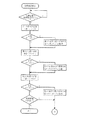
また、充電途中で何らかの理由で充電動作を中止した場合であっても、充電終了時の時と同様に、その充電中の電池ユニットに設けられた記憶手段に、途中までの充電情報を記憶させるので、その電池ユニットの充放電に際してはその当該情報を活用できる。上述した充電動作について、図7および図8のフローチャートを用いて説明する。
【0072】
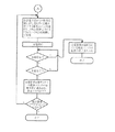
図1における充電ユニット8の充電手段5が、図7および図8のフローチャートに示す充電動作に入ると、まず図7に示すように、第1の位置に装着された電池ユニットの記憶装置(この例では電池ユニット2の記憶手段11)へアクセスして、そこに記憶されている情報(データ)を読み込む。
【0073】
次いで、そのデータが正常か否かを判断する。ここで、電池ユニットが装着されていない時のデータは全てゼロになるように回路を構成してある。この場合、例えばチェックサムデータを設けて確認する手段を利用してもよい。
【0074】
正常なデータか否かの判断の結果、正常(Y)であれば第1の位置に電池ユニットが装着されているフラグを立ててから、不正常(N)であれば何もせずに、次に第2の位置の記憶装置(この例では電池ユニット3の記憶手段12)へアクセスして、そこに記憶されている情報(データ)を読み込む。
【0075】
そして、そのデータが正常か否かを判断し、正常(Y)であれば第2の位置に電池ユニットが装着されているフラグを立ててから、不正常(N)であれば何もせずに、次に第3の位置の記憶装置(この例では電池ユニット4の記憶手段13)へアクセスして、そこに記憶されている情報(データ)を読み込む。
次いで、そのデータが正常か否かを判断し、正常(Y)であれば第3の位置に電池ユニットが装着されているフラグを立てた後、図8に示す充電の処理に進む。
【0076】
データが正常か否かの判断の結果が不正常(N)であれば、装着フラグが立っているか否かをチェックし、立っていれば第1及び/又は第2の位置に電池ユニットが装着されているので、図8に示す充電の処理に進むが、立っていなければ、どの装着位置にも電池ユニットが装着されていないと判断して、充電動作をここで終了する。
【0077】
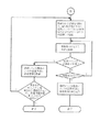
図8に示す充電動作の開始により、電池ユニットに対する装着フラグが複数ある場合は、各記憶手段から取得した情報(組蓄電池の充放電状況に関する情報)に基づいて、例えば最も早く充電が終了する電池ユニットを選択し、SW2n制御信号により、図1に示した充電ユニット8内のスイッチSW21,SW22,SW23を制御して、その電池ユニットに接続する。それによって、選択した電池ユニットの組蓄電池の充電を開始する。
【0078】
充電を開始した後は、その充電を途中で中止する充電停止指令(商用電源の切断、あるいは図示していない操作盤からの充電停止操作等に基づく指令等)がない限り充電を継続し、充電が完了する満充電まで行うのが通常の充電方法であるが、途中で充電停止指令が発せられた時は、それまで充電していた充電情報を、選択して充電していた電池ユニットの記憶手段に書き込んで充電動作を終了する。
【0079】
一方、選択した電池ユニットの組蓄電池の充電を開始すると、その充電中は、充電手段5の充電制御機能により、選択した電池ユニットの電池特性から必要有りとして予め決められた積算充電量や充電時の温度等の充電情報を、予め定められた方法で測定及び演算し、充電ユニット8内の記憶手段によって記憶保持する。
そして、選択した電池ユニットの充電が完了すると、その充電情報を選択されている電池ユニットの記憶手段に書き込む。次いでその電池ユニットに対する装着フラグをクリアする。
【0080】
その後、他の装着フラグが立っているか否かを判断して、立っていなければ(クリヤされていれば)充電動作を完了する。しかし、ここでなお装着フラグが立っている時(クリヤされていない時)は、図8の最初のステップに戻り、上述の処理を繰り返し、残った電池ユニットの中で最も早く充電が終了する電池ユニット(二番目に充電する電池ユニット)を選択して充電を開始する。その後の処理は、一番目に充電した電池ユニットに対して行なったのと同様である。
【0081】
その電池ユニットの充電を完了した後、更に他の電池ユニットの装着フラグが立っているときは、同様な動作を繰り返して全ての電池ユニットの組蓄電池の充電を完了する。
当然のことではあるが、各電池ユニットの記憶手段からの情報により、組蓄電池の充電が必要でない場合は、充電動作に入らずに装着フラグのみをクリアして対象の電池ユニットに対する処理を終える。これにより、充電直後或いは満充電状態で充電の必要がない電池ユニットの組蓄電池に再充電して過充電を流すのを防止できる。
【0082】
ここで、各電池ユニット2,3,4に設けられている記憶手段11,12,13に蓄積される情報としては、使用電池(組蓄電池2B,3B,4B)の特性及び電動装置1の特性上必要な充放電状況に関する情報で、例えば、充電回数、満充電情報、積算充電量、充電時温度、放電回数、積算放電量、残存容量、放電時温度等がある。この情報の詳細については後述する。
【0083】
次に、図1に示した電動装置1の稼動(負荷10の駆動)時の動作について説明する。
電動装置1の3個所の電池ユニット装着部の少なくとも1個所に電池ユニットが装着されていると、制御用電源7により制御手段6へ必要な電源が供給される。
【0084】
制御手段6に電源が供給されると、制御手段6が有する制御機能により各電池ユニット2,3,4に設けられた記憶手段11,12,13にアクセスし、電池ユニットの装着の有無と、装着されている電池ユニットの放電に必要な記憶手段の情報を制御手段6が取得し、それを制御手段6が有する情報記憶機能によって必要に応じて記憶保持する。
【0085】
この動作により、前述した充電手段5による場合と同様に、電動装置1に装着されている電池ユニットを認識する。図示していないが、電動装置1への稼動要求信号が制御手段6に入力されると、制御手段6が取得して保持している上述した放電に必要な情報により、例えば最も残存容量の少ない電池ユニットを選択する。実際には、組蓄電池の特性や電動装置の特性等により、放電させる電池ユニットを選択するが、この例では残存容量が最も少ない電池ユニットを選択する例で説明する。
【0086】
そして、SW1n制御信号によりスイッチSW11,SW12,SW13を切り替え、上記要求に応じて駆動手段9へ信号を送り、駆動手段9は負荷10である例えば電動機(図示せず)を駆動し、電動装置を稼動する。
【0087】
選択されて放電している電池ユニットが、予め定められた放電終了状態になると、制御手段6はその電池ユニットの記憶手段に放電情報を書き込む。そして、装着されている他の電池ユニットの記憶手段からの情報あるいは取得して格納済みの情報により、次に放電させる電池ユニットを選択し、上述と同様にスイッチSW11,SW12,SW13を切り替え、その選択した電池ユニットを接続し、放電済みの電池ユニットを切り離す。
【0088】
また、放電途中において駆動手段9による電動装置1の稼動要求がなくなった場合でも、放電情報は使用中の電池ユニットの記憶手段に書き込まれる。
【0089】
この電動装置の稼働時の動作について、図9及び図10のフローチャートによって説明する。
図1における制御手段6は、図9に示す最初のステップで電動装置の稼動要求の有無を判断し、稼働要求がなければ待機し、あれば直ちに次のステップへ進んで第1の位置の記憶手段(図1の例では電池ユニット2の記憶手段11)へアクセスし、その情報を読み込む。そして、それが正常なデータ(情報)か否かを判断する。
【0090】
その結果、正常(Y)であれば、第1の記憶手段の情報を所定メモリエリアに格納する。この場合も、充電動作において説明したのと同様に、装着フラグを立て、記憶手段の情報が必要な場合はその都度その電池ユニットの記憶手段にアクセスするようにしてもよい。
【0091】
上記判断の結果が不正常(N)の場合は直ちに、正常(Y)な場合は上述の処理を行なった後、次に第2の位置の記憶手段(図1の例では電池ユニット3の記憶手段12)へアクセスし、その情報を読み込む。そして、それが正常なデータ(情報)か否かを判断する。
【0092】
その判断の結果が不正常(N)の場合は直ちに、正常(Y)な場合は第2の記憶手段の情報を所定のメモリエリアに格納した後、次に第3の位置の記憶手段(図1の例では電池ユニット4の記憶手段13)へアクセスし、その情報を読み込む。そして、それが正常なデータ(情報)か否かを判断する。
【0093】
その判断の結果が正常(Y)であれば、第3の記憶手段の情報を所定のメモリエリアに格納して、図10に示す稼働処理へ進む。
上記判断の結果が不正常(N)の場合は、所定のメモリエリアに格納情報があるか否かを判断し、あれば図10に示す稼働処理へ進むが、なければ第1乃至第3の装着位置のいずれにも電池ユニットが装着されていないと判断して、この処理をここで終了する。
【0094】
図10の最初のステップの処理は、所定のメモリエリアに格納された情報の内容を比較して、例えば最も残容量の少ない電池ユニットを選択して、SW1n制御信号によりスイッチSW11,SW12,SW13を制御して、その選択した電池ユニットを制御手段6及び駆動手段9に接続する。
【0095】
そして、その選択した電池ユニットの組蓄電池を放電させて電力を供給し、稼動要求に応じて負荷10を駆動して電動装置1を稼動する。その電池ユニットの組蓄電池の残存容量があり、稼動要求が継続する間はその電池ユニットは放電を続ける。稼動要求がなくなった時は、それまでの放電情報を、選択している電池ユニットの記憶手段に書き込んだ後、処理を終了する。
【0096】
また、電池ユニットを選択して放電を開始させると、その放電中は制御手段6の制御機能により、電池特性及び電動装置特性から必要とされる予め決められた積算放電量及び放電時温度等を、予め決められた方法で測定及び演算し、制御手段6の情報記憶機能によって記憶保持する。また、必要に応じて当該選択されている電池部の記憶手段に書き込む。
【0097】
一方、その稼動要求が継続しているにも拘わらずその途中において、選択した電池ユニットが放電終了の状態になった時は、それまでの放電情報をその選択した電池ユニットの記憶手段及び必要があれば他の記憶手段、例えば制御手段6が有する情報記憶機能で使用する記憶手段に格納する。
【0098】
次いで、前述の所定のメモリエリアに格納された情報をチェックし、放電可能な他の電池ユニットがあるか否かを判断し、NOの場合は処理を終了するが、YESの時は図10の最初のステップに戻って、上述の処理を繰り返し、装着されている他の電池ユニットのうち、次に残容量が少ない電池ユニットを選択して放電させ、稼働要求がある間負荷を駆動する。
【0099】
図4は、図1に示した電動装置1から、充電ユニット8及び複数の電池ユニット2,3,4を取り外して充電する場合の接続状態を示す図であり、その充電動作は前述した電動装置1に搭載した状態での充電動作と同様である。
【0100】
この例では、電動装置1から、充電手段8と3組の電池ユニット2,3,4を同時に取り外して充電する状態を示しているが、電動装置1に搭載した複数の電池ユニットを、必ずしも全てを同時に取り外して充電する必要はない。
例えば、電動装置1に搭載された複数の電池ユニットの内、放電を終了した電池ユニット、もしくは組蓄電池の残容量が少なくなった電池ユニットのみを、充電ユニット8と共に取り外して充電すれば、その電池ユニットを再び搭載するまでは残りの電池ユニットを使用して稼動要求に応じて負荷10を稼動出来る。
【0101】
また、充電ユニット8を電動装置1に固定して設けたり、電動装置に搭載したまま電池ユニットの充電を行なう場合には、その充電ユニット8に商用電源100を接続する必要があるため、電動装置1自体を商用電源100を接続できる所に停止させておかなければならず、充電中は使用できなくなる。したがって、夜間等の使用しない時間帯に充電を行なわなければならない。
【0102】
しかし、この実施形態のように、充電ユニット8と電池ユニット2,3,4を、いずれも電動装置1の本体に着脱可能に搭載し、充電ユニット8と充電が必要な電池ユニットのみを電動装置1から取り外して充電するようにすれば、電動装置1を商用電源に接続する必要はなく、充電中も上述のように残りの電池ユニットを使用して負荷を駆動し、自由に走行することができる。
【0103】
この充電ユニット8と、図示は省略しているが、その充電ユニット8と1個または複数の電池ユニットを着脱自在に装着できる充電ユニット装着部と電池ユニット装着部とを一体に設け、商用電源への接続コードを設けた充電用ホルダを準備し、その充電ユニット装着部と電池ユニット装着部に、それぞれ、充電ユニット8および電池ユニット2等との電気的な接続のための各コネクタを構成する固定端子(充電ユニット8および電池ユニット2等の対応する各端子と接続する)を設けるとよい。
【0104】
そうすれば、その充電用ホルダの接続コードを商用電源に接続し、充電ユニット装着部に充電ユニット8を装着し、電池ユニット装着部に充電したい電池ユニットを装着するだけで、充電ユニット8と装着した電池ユニットとの間の各コネクタ間の接続が全て完了し、直ちに充電を開始することができる。
この充電ユニット8と充電用ホルダによって、この発明による充電装置を構成することができる。電動装置に搭載しない充電装置とする場合には、充電ユニット8と充電用ホルダを一体化して充電装置を構成することができる。
【0105】
〔第2の実施形態〕
図2は、この発明の第2の実施形態を示す電池ユニットを搭載した電動装置のブロック回路図であり、図1と同じ部分には同一の符号を付してあり、それらの説明は省略あるいは簡略にする。
【0106】
この第2の実施形態の電池ユニット22,23,24は、それぞれ第1の実施形態の電池ユニットと同様に組蓄電池2B,3B,4Bとその充放電状況に関する情報を記憶する記憶手段11,12,13とを対にして一体化するとともに、それぞれ図1の充電ユニット8に設けた充電手段5と同様な充電手段25,26,27を内蔵している。したがって、この場合の電池ユニット22,23,24は電源ユニットとも言える。
【0107】
そして、この各電池ユニット22,23,24は、電動装置1の本体に着脱可能に搭載される。その各電池ユニット2,3,4と装置本体の電池ユニット装着部(図示せず)とには、それぞれ電池ユニット22,23,24の着脱に伴って装置本体側との電気的な接離を行なう接続手段として、それぞれ対の端子からなるコネクタCa1,Ca2,Ca3、コネクタCb1,Cb2,Cb3、およびコネクタCc1,Cc2,Cc3を設けている。
【0108】
この実施形態の電動装置1は、それぞれ充電手段を内蔵した複数の電池ユニット22,23,24を搭載するので、図1における充電ユニット8は搭載しない。その他の構成、すなわち制御手段6、制御用電源7、制御手段6の要求により電動機等の負荷10を駆動する駆動手段9、および制御手段6からのSW1n制御信号により放電(給電)させる電池ユニットを切り換えるための3個のスイッチSW11,SW12,SW13を備える点は、第1の実施形態と同様である。
【0109】
各電池ユニット22,23,24の充電手段25,26,27は、それぞれ商用電源100と直接に接続され、且つ、それぞれ同じユニット内の記憶手段11,12,13に記憶されている情報を参照して、同じユニット内の組蓄電池2B,3B,4Bを充電するように構成されている。電池ユニットを3組搭載した例を示しているが、2組以上搭載すればよい。
【0110】
次に、この実施形態の電動装置における充電動作について説明する。
商用電源100もしくはそれに代わる電源が、複数の電池ユニット22,23,24の充電手段25,26,27に供給されると充電動作に入る。
【0111】
まず、各電池ユニット22,23,24は、それぞれ同じユニット内の記憶手段11,12,13にアクセスし、充電に必要な各組蓄電池2B,3B,4Bに記憶されている情報を読み出して取得し、同じユニット内の組蓄電池の充電が必要であると判断するとその組蓄電池に対して充電を開始する。そして、その組蓄電池が満充電になった時は、その充電情報を同じユニット内の記憶手段に書き込んで充電動作を終了する。
【0112】
また、充電途中で充電動作を打ち切った時は、それまでの充電情報を、充電終了の場合と同様にして同じユニット内の記憶手段に書き込み、以後の充放電の際にその情報を活用できるようにする。
【0113】
上述の充電動作は、複数の電池ユニット22,23,24がそれぞれ独立して充電処理を行なうようにした例である。しかしながら、複数の電池ユニットで同時に充電が行われると、商用電源100あるいはそれに変わる電源への要求電力が大きくなり、例えば家庭用電源の場合にはブレーカスタックが落ちるという不都合が生じる可能性がある。
【0114】
このような問題を解決する手段としては、後述する図12によって説明するように、それぞれ各電池ユニット22,23,24が有する充電手段25,26,27間を図示しないコネクタと信号線によって接続するようにし、その信号線による情報交換ルートにより、各充電手段25,26,27が相互に情報を授受し、組蓄電池2B,3B,4Bを充電する順位を決めて、順次充電するように制御することもできる。
【0115】
各記憶手段11,12,13が有する情報の内容如何により、必要な商用電源もしくはそれに代わる電源を用意するか、あるいは商用電源もしくはそれに代わる電源の電力容量に見合った電力要求となるようにして順次充電を行うか、あるいは複数の組蓄電池2B,3B,4Bの充電量を制御してこれに対応することができる。
【0116】
一方、この実施形態においては、各電池ユニット22,23,24では、それぞれ組蓄電池2B,3B,4Bと充電手段25,26,27とが常時接続されているので、図示は省略しているが例えばダイオード又は逆流防止回路等を組蓄電池と充電手段との間に介挿して、組蓄電池2B,3B,4Bから充電ユニット25,26,27への電流の逆流防止を図る必要がある。
【0117】
次に、以上説明したこの電動装置における充電動作を、図11及び図12のフローチャートによってさらに詳細に説明する。
図11のフローチャートによる充電動作は、図2に示した各電池ユニット22,23,24の充電手段25,26,27が、それぞれ独立して充電動作を行なう場合である。
【0118】
商用電源100あるいはそれに代わる電源が、各電池ユニット22,23,24の充電手段25,26,27に供給されると、その各充電手段25,26,27が図11のフローチャートに示す充電動作に入る。どの電池ユニットでも同様な動作を行なうが、以下に電池ユニット22の場合を例に説明する。
【0119】
電池ユニット22において、充電手段25はまず記憶手段11にアクセスし、そのデータが正常か否かを判断する。正常な場合は、その記憶手段11から取得した情報から組蓄電池2Bの充電の必要性を判断する。そして、充電が必要と判断すると、組蓄電池2Bの充電を開始する。充電を開始した後は当該充電の停止指令がない限り充電を継続し、充電が完了したか否かを判断し、完了すると、そのときの充電情報を記憶手段11に書き込んで充電動作を終了する。
【0120】
充電動作を開始し、記憶手段11にアクセスした結果、正常データでなかった時はエラーとして充電動作は行わない。このような場合は、その原因追求等の処置をした後、再び充電動作に入ることになる。また、記憶手段から取得した情報から組蓄電池2Bの充電の必要性を判断した結果、充電不要と判断したときは、それで充電動作を終了する。
【0121】
一方、充電を開始した後充電停止の指令があった時は、充電途中であってもそれまでの充電情報を、記憶手段11に書き込んで充電動作を終了するようにしている。
【0122】
ところで、上述のような充電動作を複数の電池ユニットで同時に行うと、既に説明したように、要求電力が大きくなり過ぎて、商用電源100の給電路に設けられたブレーカスタックが落ちる場合がある。
このような不都合の発生を防止するために、図12のフローチャートに示す順次充電を行なうとよい。
【0123】
この場合は、図2に示した電動装置1に搭載されている各電池ユニット22,23,24の充電手段25,26,27の間に、相互に情報を授受できるルートを設けておく。そして、各充電手段25,26,27が、それぞれ記憶手段11,12,13から取得した情報を交換して、各組蓄電池2B,3B,4Bの充電順序を任意に決めることが出来る。
【0124】
例えば、各記憶手段から取得した情報に基づいて、各組蓄電池の残存容量から充電必要量を求め、時間換算して必要充電時間を算出し、その必要充電時間が短い電池ユニットの組蓄電池から順に充電する方法がある。また、各組蓄電池の残存容量が少ない(最も放電した)順に充電する方法、あるいは残存容量の大小に関係なく、各電池ユニットの組蓄電池を予め決めた順に充電する方法もある。
さらに、単位時間当たりの充電容量が大きい組蓄電池から順次充電する方法等もある。
【0125】
図12のフローチャートに示す例では、最初のステップで、装着されている各電池ユニット22,23,24の充電手段25,26,27が、互いに他の電池ユニットの充電手段と情報の授受を行ない、装着されている電池ユニットの数をそれぞれ認識し、充電の必要性と充電時間の情報を得る。
【0126】
次いで、充電が必要な電池ユニットの数を判断する。その判断の結果、充電が必要な電池ユニットの数が3の場合は、充電時間の短い方から2つの電池ユニットを選び、その各組蓄電池に充電を開始する。充電が必要な電池ユニットの数が3でない場合は、その充電が必要な電池ユニットの充電を開始する。
そして、充電中も各充電手段25,26,27は常に他の電池ユニットと情報の授受を行い、相互に組蓄電池の充放電状況に関する最新の情報を得る。
【0127】
充電中に充電停止指令があると、充電動作中の充電手段が同じユニットの記憶手段にそれまでの充電情報を書き込んで、充電動作を終了する。
充電停止命令がなければ充電動作を継続し、充電を完了したものがあるか否かの判断をする。その判断の結果、なければ各充電手段間で情報の授受を行ないながら充電動作を継続する。
【0128】
充電を完了したものがあると、充電を完了した電池ユニットの充電手段は、そのとき有する充電情報を同じユニットの記憶手段に書き込む。
次いで、各充電手段相互間の授受情報に基づき、さらに充電が必要な電池ユニットがあるか否かを判断し、あれば充電が必要な電池ユニットの数が3か否かの判断に戻り、上述の充電動作を繰り返し、充電が必要な電池ユニットの組蓄電池の充電を行なう。
【0129】
そして、その充電を完了した後、充電が必要なものがあるかの判断の結果が「ない」の場合は、必要な全ての電池ユニットの組蓄電池への充電が完了したと判断して、充電動作を終了する。
【0130】
次に、この第2の実施形態における充電電力制御に関する充電電力(充電量)の制限プロセスを、図13及び図14のフローチャートによって説明する。
Ni-Cd電池やNi-MH電池のように定電流充電で−ΔVあるいはΔV(高精度)ピークを検出するものでは、充電電流を抑えて充電電力を落とすことは困難であるが、リチウム−イオン、鉛電池のように定電圧・定電流充電のものは、充電電流を落として充電電力を落とすことが容易となる。
【0131】
そこで、以下に説明する例では、電池の種類は別として充電電流(電力)を制御することができ、さらに、充電電圧及び充電電流の検知を可能にし、充電電力を算出する機能を持たせている。
【0132】
商用電源100を用いて複数の電池ユニット22,23,24の各充電手段25,26,27が、図13に示す充電電力制御動作を開始すると、まず、電動装置1に装着されている各電池ユニットの充電手段が、他の電池ユニットの充電手段と情報の授受を行ない、装着されている各電池ユニットの充電の必要性と充電時間の情報を得る。
【0133】
次いで、充電が必要な電池ユニットはあるか否かの判断を行ない、充電が必要な電池ユニットがない時は、それで全ての充電手段の充電動作を終了する。
充電が必要な電池ユニットがある時は、充電時間の最も短い電池ユニットは、商用電源からの電力量を超えず、且つ充電手段の最大能力の範囲内で充電を開始する。
【0134】
ここで商用電源の電力量とは、例えば、充電電圧と充電電流および充電部の効率から商用電源の電力量を求めることが出来る。充電を開始した後も、複数の電池ユニット各充電手段はその充電制御機能によって、商用電源の電力量を含む充電情報の授受を行う。その後図14に示す終了まで処理は、上記処理の繰り返しと図12によって説明した順次充電の場合と同様な処理を行なうので、その説明を省略する。
【0135】
以上説明したように、この実施形態においては、常に各充電手段25,26,27の間で充電情報の授受を行うことにより、搭載されている全ての電池ユニットの充電情報を各々が把握し、各電池ユニット22,23,24の組蓄電池2B,3B,4Bのいずれかの充電が完了した時、もしくはその途中においても、常に次に充電を必要とする電池ユニットがあるかどうかを判断する。
【0136】
そして、それがある時は、次に充電時間の短い電池ユニットが商用電源100からの電力量を超えず、且つ充電手段の最大能力内で充電を開始する。
つまり、各電池ユニットの充電手段それぞれが、互いに他の全ての電池ユニットの充電手段の充電情報を把握していることにより、各々が商用電源100に要求している総電力を把握出来る。
【0137】
この総電力の把握により、各充電手段は自己の充電電力を調整して、常に商用電源100の能力以内での並行充電を可能にする。
このことは、例えばリチウム−イオン電池のように、定電流・定電圧方式で充電を行なう電池の場合で言えば、定電流からスタートし、電圧が低いときには充電電力が小さく、電圧が上がって行くに従って充電電力が増大し、規定された電圧で定電圧モードに入る時に充電電力が最大となり、その後充電電流の減少により充電電力が減少するという特性を持っている。
【0138】
このように、充電状態により必要な充電電力が変化する特性を利用して、商用電源の許容電力一杯で各充電手段を動作させることにより、効率の良い充電が可能になる。これは、定電流・定電圧方式で充電する電池についての記述であるが、他の特性を持つ電池であっても、その特性の把握と充電制御により、当然同様な効果を得ることが出来る。
【0139】
図13及び図14で説明した例では、充電時間が最も短い電池ユニットの組蓄電池から順に充電を開始するようにしているが、これを充電電力が大きな電池ユニット部から充電、あるいは充電電力が小さい電池ユニットから充電等に変更してもよい。いずれにしても、組蓄電池の電池特性や電動装置の特性に合った充電順序を決めて充電することにより、その目的は達成される。
【0140】
このようにして組蓄電池を充電し終わった電池ユニットは、その充電手段がそのとき充電制御手段により充電情報をその記憶手段に書き込んで全ての電源手段の充電が終了するまで待機し、全ての充電が終了することにより、充電動作は完了する。又、商用電源の切断或いは充電停止操作により充電が停止された時は、充電動作を開始していた電源手段は、前記同様にそれまでの充電情報を各々の記憶手段に書き込んで終了する。
【0141】
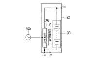
図5は、図2における1組の電池ユニットを、電動装置1から取り外して組蓄電池を充電する場合の充電方法を示した図であり、電池ユニット22の例を示している。前述した電動装置1上での充電方法と相違する点は、複数の電池ユニットの各組蓄電池を順次充電するのではなく、各電池ユニット22,23,24をそれぞれ電動装置1から取り外し、その充電手段25,26,27を商用電源100に接続して、単体でその組蓄電池2B,3B,4Bをそれぞれ充電し、再び電動装置1に搭載するのである。
【0142】
また、複数の電池ユニットを取り外す場合には、電動装置1に搭載時と同様に、各電池ユニットの充電手段相互間で充電情報の授受が可能のように接続すれば、一つの商用電源取り出し口に複数の電池ユニットを接続した時でも、その商用電源の許容電力内での並行充電動作が可能になる。
【0143】
この実施形態によれば、電動装置に充電ユニットを搭載したり、あるいは別に充電装置を備える必要がなく、商用電源さえあれば、いつでも何処でも、電池ユニット毎にその組蓄電池を充電することができる。また、複数の電池ユニットの組蓄電池を充電する場合には、上述のような順次充電や充電電力制御を容易に行なうことができる。
【0144】
〔第3の実施形態〕
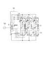
図3は、この発明の第3の実施形態を示す電池ユニットを搭載した電動装置のブロック回路図であり、図1と同等な部分には同一の符号を付してあり、それらの説明は省略する。
【0145】
この図3に示す第3の実施形態の電池ユニット32,33,34は、それぞれ第1の実施形態の電池ユニットと同様に、組蓄電池2B,3B,4Bとその充放電状況に関する情報を記憶する記憶手段11,12,13とを対にして一体化するとともに、それぞれ組蓄電池2B,3B,4Bと直列にスイッチSWa,SWb,SWcを設けている。
【0146】
この各スイッチは、図1における充電ユニット8内に設けたスイッチSW21,SW22,SW23と、制御手段6に制御されるスイッチSW11,SW12,SW13とを兼ねた機能を果たし、製品のコストダウンを図ることができる。
【0147】
そして、この各電池ユニット32,33,34は、電動装置1の本体に着脱可能に搭載される。その各電池ユニット32,33,34は、それぞれ組蓄電池2B,3B,4BとスイッチのSWa,SWb,SWcの直列回路およびその各スイッチSWa,SWb,SWcの制御端子、並びに記憶手段11,12,13を外部に接続するための端子(コネクタBa1〜Ba6,コネクタBb1〜Bb6,およびコネクタBc1〜Bc6のそれぞれユニット側の端子)を設けている。
【0148】
そして、電動装置1の各電池ユニット装着部には、各電池ユニット32,33,34の着脱に伴って上記各端子と電気的に接離するコネクタBa1〜Ba6,コネクタBb1〜Bb6,およびコネクタBc1〜Bc6のそれぞれ固定端子を設けている。
【0149】
この第3の実施形態の電動装置1は、上述した複数の電池ユニット32,33,34を搭載すると共に、充電手段5を設けた充電ユニット18を着脱可能に搭載している。さらに、制御手段6、制御用電源7、および制御手段6の要求により電動機等の負荷10を駆動する駆動手段9を備えている点は図1に示した第1の実施形態と同様であるが、制御手段6に制御されるスイッチSW11,SW12,SW13は設けていない。
【0150】
その充電ユニット18は、図1における充電ユニット8からスイッチSW21,SW22,SW23を省略して、3つのコネクタCr1,Cr2,Cr3にそれぞれSW制御信号を個別に出力するようにし、図1における3個のアース側コネクタCg1,Cg2,Cg3を1個のアース側コネクタCg1にまとめたものである。
【0151】
この実施形態では、各電池ユニット32,33,34内にそれぞれスイッチSWa,SWb,SWcを設けたことに対応して、充電ユニット18の充電手段5は、その充電制御機能に基づくSW制御信号によって、各電池ユニット32,33,34内のスイッチSWa,SWb,SWcをそれぞれ個別に開閉制御する。
また、制御手段6も、その制御機能に基づくSW制御信号によって、各電池ユニット32,33,34内のスイッチSWa,SWb,SWcをそれぞれ個別に開閉制御できる。
【0152】
ここで、充電手段5からのSW制御信号と制御手段6からのSW制御信号の何れかに優先度を持たせ、例えば充電手段5に優先度を持たせる場合、商用電源100に接続されたことを検知して制御手段6にその情報を伝え、制御手段6からのSW制御信号の出力を禁止することにより、3個のスイッチSWa,SWb,SWcの正常な動作が確保される。
【0153】
また、制御用電源7の機能である何れかの電池ユニットが搭載された時に、制御手段6に必要な電力供給を行うため、電池ユニット32,33,34のスイッチされない組蓄電池2B,3B,4Bの出力を制御用電源7に供給するためのコネクタ回路が設けられている。
【0154】
この第3の実施形態の電動装置における充電動作は、図1に示した第1の実施形態における充電ユニット8内の各スイッチSW21,SW22,SW23を、各電池ユニット32,33,34内にそれぞれ設けたスイッチSWa,SWb,SWcに置き換えたこと、およびSW2n制御信号を、SW制御信号に置き換えた点に相違はあるものの、それ以外は、図7及び図8に示した第1の実施形態における充電動作と同様であるので、ここでは説明を省略する。
【0155】
この第3の実施形態の電動装置1による稼働(負荷駆動)動作は、図1に示したスイッチSW11,SW12,SW13を、各電池ユニット32,33,34内にそれぞれ設けたスイッチSWa,SWb,SWcに置き換えたこと、及び第1の実施形態(図1)におけるSW1n制御信号を、SW制御信号に置き換えた点に相違があるが、それ以外は、図9および図10に示した第1の実施形態の電動装置1の動作と同様であるので、ここでは説明を省略する。
【0156】
図6は、図3に示した電動装置1から、充電ユニット18及び複数の電池ユニット32,33,34を取り外して充電する状態を示すものである。その充電動作は、図7及び図8のフローチャートによって説明した第1の実施形態による充電動作とと同様であるので、ここでは省略する。
【0157】
なお、図2に示した第2の実施形態の電池ユニット22,23,24においても、それぞれ組蓄電池2B,3B,4Bに直列にスイッチを外部からオン/オフ制御可能に設けることにより、スイッチSW11、SW12、SW13を省略することが可能である。
【0158】
次に、この発明の最も特徴とする点、すなわち組蓄電池とその充放電状況に関する情報等を記憶する記憶手段(メモリ)とを対にして一体化し、電池ユニットを構成したことによる効果について説明する。
【0159】
この発明による電池ユニットの記憶手段に記憶させる情報としては、少なくとも同じユニット内の電池(組蓄電池)の充放電状況に関する情報を含む次のような種々の情報がある、
(1) 電池の定格容量、充電特性、放電負荷特性、サイクル特性、保存特性、温度特性等の電池特性。
【0160】
(2) 充電開始電圧、充電積算容量、充電時温度、放電積算容量、放電時温度、放電終了時電圧、残容量、放電サイクル数、充放電容量実績、使用時温度等の充放電履歴。
(3) 電池の容量、充電特性、放電負荷特性等の電池特性、及び電池の管理・制御に使用している基本定数等の補正データ。
これらの電池特性による管理情報、電池使用時の環境・実績情報、電池の使用実績による各情報の補正情報、必要に応じて電池に影響を与える電動装置の特性情報等がある。
【0161】
このように、この発明は、電池ユニットに記憶手段を一体化して取り扱うことにより、電池ユニット内の電池(組蓄電池)の容量、充電特性、放電負荷特性等の電池特性の状態を常時把握できる。その結果、次のような多くの効果が得られる。
【0162】
(1) 各電池ユニットの記憶手段により、完全(満)充電あるいは中途充電、放電途中等の電池の状態に関係なく、残量管理下での使用が可能になり、電池ユニットの自由な入れ替えができる。
【0163】
(2) 各電池ユニットの記憶手段の情報により、少残容量の電池ユニットから充電するか、多残容量の電池ユニットから充電するか、あるいは補正サイクル数の情報に基づき、充放電サイクル数の少ない電池ユニットから充電して使用率を平均化するか、等の充電順序の判定が出来、使用者の意思あるいは電池及び電動装置の特性に合ったものから充電することができる。
【0164】
(3) 各電池ユニットの記憶手段の情報に基づき、メモリ効果が生じる電池を使用した場合に、少残容量の電池ユニットからの放電、あるいは履歴情報によりメモリ効果が生じやすい電池ユニットから放電して、放電終了電圧まで放電する機会を増加してメモリ効果を防止したり、充放電サイクル数の少ない電池部から放電して使用率を平均化する等の放電順序の判定ができる。
【0165】
(4) 充放電履歴情報の容量変化率、充放電の繰り返し情報等により、メモリ効果が生じる可能性がある時は自動的にリフレッシュ後の充電としたり、残容量が規定値以下の場合のみ自動的にリフレッシュを行なうようにして、リフレッシュ時間の短縮が図れる。
【0166】
(5) 各電池ユニットの記憶手段の充放電履歴情報における充電情報および放電情報から、充放電順序を最適に決定することにより完全充電又は完全放電の確率の増加を図り、充放電動作の区切りで電池の残存容量管理の補正を行うことにより、電池ユニットの電池の残存容量の検知精度を向上でき、的確な電動装置の稼動が可能になる。
【0167】
(6) 各電池ユニットの記憶手段からの充放電サイクル数、充放電容量実績等の使用履歴情報により、電池の寿命の判定が可能になり、例えば充放電回数の少ない電池ユニットから放電させるなど、電池寿命の平均化を図ることができる。
【0168】
(7) 特にNi-Cd、Ni-MH電池等のメモリ効果が生じる特性を有する電池を使用する場合、充放電履歴情報における放電終了電圧情報に基づき、放電順序により放電終了電圧への到達率の向上を図り、メモリ効果が生じやすい電池ユニットから放電を開始することにより、メモリ効果を回避することができる。
【0169】
(8) 電池ユニットの記憶手段からの電池の定格容量、放電負荷特性等の電池特性情報と、充放電履歴情報及び補正データ等に基づき、同種類の電池であるが各電池ユニット間の容量が異なる電池を管理することにより、異容量電池の混在使用ができる。
【0170】
(9) 複数の電池ユニットの構成において、異種の電池を設けた電池ユニットが混在する場合であっても、各電池ユニットの記憶手段の電池特性情報、充放電履歴情報、及び補正データ等に基づき、それぞれの各電池を管理することにより、異種電池の混在使用ができる。
【0171】
(10)電池(組蓄電池)と、電池特性情報や充放電履歴情報及び補正データ等の情報を記憶する記憶手段とを対にし、一体化して電動装置に脱着可能なユニットとしたことにより、複数の電池ユニットを有する電動装置で電池ユニットの共用化が可能になるため、電池スタンド等による電池充電の利便化が図れる。
【0172】
(11)電動機を使用した場合、電池部を複数に分割したこと、及び電池部と記憶手段を一体化したことにより、その回生電力を搭載した電池ユニットの放電深度の深い電池に供給することにより、より大きな回生電力の回収が可能になり、回収効率の向上を図れる。
【0173】
(12)必要容量の電池ユニットを複数搭載することにより、単一の電池ユニットのみでも電動装置を稼動でき、且つその電池ユニットが稼動中であっても他の電池ユニットを充電することができる。
(13)各電池ユニットに充電手段を一体に設けた場合には、各電池ユニットの同時充電が可能になり、充電時間の短縮を図れる。
【0174】
【発明の効果】
以上説明してきたように、この発明によれば、電動二輪車や電動車椅子等の電動装置の駆動エネルギ源となる電池部を、取り扱い容易にし、且つ常に効率よく利用することができる。
すなわち、人手による電池部の取外し及び持ち運びを容易にし、充電の際に必ずしも電動装置を商用電源に接続できる場所に移動させる必要がなくなるとともに、電池部を搬送するための特別な運搬装置も不要になる。
【0175】
また、特別な充電装置を必要とせず、複数組の電池部を設けた電動装置の稼動と電池部の充電を並行して行なうことも可能になる。さらに、電池部の電池特性の管理が可能で、複数組の電池部の充放電をその各電池特性に合わせて自由に選択することもできる。したがって、異なる種類の組電池でも組み合わせて使用可能になる。
【0176】
電動装置の電池部として、Ni−Cd電池のようにいわゆるメモリ効果が生じる二次電池(蓄電池)を使用する場合のメモリ効果を防止し、そのリフレッシュを不要にすることもできる。それによって、電池の長寿化を図ることができる。
【0177】
また、電池スタンドなどに充電装置を設置して充電の利便化を図ることができ、電池部を電動装置から取り外しても、その充放電状況を高精度で知ることができるので、常に最適な充電制御が可能になる。
さらに、電動機等の負荷側からの回生電力を電池部に効率よく還元して、有効に活用することもできる。
【図面の簡単な説明】
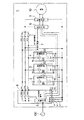
【図1】 この発明の第1の実施形態を示す電池ユニットを搭載した電動装置のブロック回路図である。
【図2】 この発明の第2の実施形態を示す電池ユニットを搭載した電動装置のブロック回路図である。
【図3】 この発明の第3の実施形態を示す電池ユニットを搭載した電動装置のブロック回路図である。
【図4】 図1に示した電動装置から充電ユニット及び複数の電池ユニットを取り外して充電する場合の接続状態を示す図である。
【図5】 図2に示した電動装置から1個の電池ユニットを取り外して充電する場合の図である。
【図6】 図3に示した電動装置から充電ユニット及び複数の電池ユニットを取り外して充電する場合の接続状態を示す図である。
【図7】 図1に示した電動装置における充電手段による電池ユニットの充電動作を示すフローチャートである。
【図8】 同じくその続きのフローチャートである。
【図9】 図1に示した電動装置の稼働時における制御装置による動作を示すフローチャートである。
【図10】 同じくその続きのフローチャートである。
【図11】 図2に示した電動装置における各電池ユニットの充電手段による独立した充電動作を示すフローチャートである。
【図12】 図2に示した電動装置における各電池ユニットの充電手段が相互に情報を授受して、各組蓄電池を順次充電する場合の動作を示すフローチャートである。
【図13】 図2に示した電動装置における各電池ユニットの充電手段が相互に情報を授受して、各組蓄電池を充電電力制御しながら充電する場合の動作を示すフローチャートである。
【図14】 同じくその続きのフローチャートである。
【図15】 従来の組蓄電池及びその充電装置を搭載した電動装置の一例を示すブロック図である。
【図16】 従来の組蓄電池及びその充電装置を搭載した電動装置の他の例を示すブロック図である。
【図17】 従来の組蓄電池及びその充電装置を搭載した電動装置のさらに他の例を示すブロック図である。
【図18】 従来の組蓄電池を搭載した電動装置と別に設けた充電装置による組蓄電池の充電状態の例を示すブロック図である。
【図19】 従来の組蓄電池を搭載した電動装置と別に設けた充電装置による組蓄電池の充電状態の他の例を示すブロック図である。
【図20】 従来の組蓄電池を搭載した電動装置と別に設けた充電装置による組蓄電池の充電状態のさらに他の例を示すブロック図である。
【符号の説明】
1:電動装置 2,3,4:電池ユニット
2B,3B,4B:組蓄電池
5:充電手段 6:制御手段
7:制御用電源 8,18:充電ユニット
9:駆動手段 10:負荷(電動機等)
11,12,13:記憶手段
22,23,24:電池ユニット
25,26,27:充電手段
32,33,34:電池ユニット
100:商用電源[0001]
BACKGROUND OF THE INVENTION
The present invention relates to an electric device such as an electric vehicle such as an electric motorcycle or an electric wheelchair that uses electric energy from a battery as a power source, a charging device for charging the battery unit, and a method for charging and discharging the battery unit. It is.
[0002]
[Prior art]
There is an electric vehicle equipped with an assembled battery composed of a plurality of storage batteries as a power source, such as an electric motorcycle and an electric wheelchair. In this type of electric vehicle, a motor is driven by electric energy (electric power) from a built-in battery, and the vehicle travels only by the driving force, or a vehicle that travels by the combined force of the driving force and human power of the motor. Alternatively, there are vehicles that switch between the driving force of a gasoline engine and the driving force of a motor.
[0003]
Storage batteries mounted as power sources in these vehicles and the like need to be charged frequently. As charging methods, a single charging method that removes and charges from a vehicle, and an in-vehicle charging method that charges while mounted on the vehicle. There is.
[0004]
For example, in an electric device such as an electric vehicle, it may be necessary to mount a large capacity storage battery that is heavier than the weight of the vehicle body. In that case, since the weight of the battery is large, it is difficult to manually remove or carry the storage battery. For this reason, a vehicle that is an electric device is also provided with a charging device, and a method of charging the vehicle by moving the vehicle near a commercial power source is employed. Moreover, when the weight of the storage battery mounted on the vehicle is relatively small, a method may be employed in which the storage battery is detached from the vehicle and connected to a separately installed charging device for charging.
[0005]
Here, a conventional electric device using an assembled battery as a storage battery and a charging method for the assembled battery will be described with reference to FIGS. 15 to 20. 15 to 17 are examples of an electric device in which a battery unit and a charging device thereof are fixedly mounted. Each of the
[0006]
And these electric devices supply the electric power by the discharge of the
[0007]
An
[0008]
The electric apparatus 210 shown in FIG. 16 has a plurality of sets of assembled
The
[0009]
These
[0010]
In addition, since these
[0011]
The
[0012]
On the other hand, the
[0013]
When charging the
[0014]
As the assembled
[0015]
[Problems to be solved by the invention]
In such an electric device, when the battery capacity and supply power of the battery unit are not so much required as in an electric assist bicycle, the battery unit has a weight that can be easily carried by human power. It is easy to remove the part from the vehicle and charge it. However, since the battery unit of a general electric device has a considerable weight, in order to charge it, the electric device (vehicle) itself is moved to a place where a rechargeable power source such as a commercial power source is provided, or the battery unit There is an inconvenience that the battery must be transported to a place where the charging device is provided by some means of transportation.
[0016]
In addition, since each of the electric devices described above has only one
[0017]
Alternatively, it is necessary to charge the battery unit that has become unusable due to the storage state of the assembled battery being lower than the specified value. In that case, the electric device can be used unless a sufficiently large charging device is used. There is a problem that it takes a long time to charge the battery until it is in a state.
[0018]
Furthermore, when the battery unit is configured by connecting a plurality of assembled batteries or assembled battery units in parallel to the battery unit, as in the electric devices shown in FIGS. 17 and 18 or FIGS. 19 and 20 described above, In order to prevent variation in the charge amount for each assembled battery or assembled battery unit, a means for keeping the variation within an allowable range or controlling the variation is required.
[0019]
In particular, when a nickel-cadmium (Ni-Cd) battery or nickel-hydrogen (Ni-MH) battery is used in the battery part, if the battery is repeatedly charged and discharged at a shallow discharge depth, Since a so-called memory effect in which the capacity is reduced is produced, a means for preventing this is required.
When regenerative power from the load side of an electric motor or the like is returned to the battery unit, charging may be impossible depending on the state of the battery unit, that is, the degree of discharge, and the regenerative power cannot be efficiently stored. It was.
[0020]
Therefore, depending on the characteristics of the electric vehicle, the assembled battery of the required capacity is mounted in a divided form, and the assembled batteries can be connected in series or in parallel, and charged or discharged individually or in combination as necessary. Can improve the heat dissipation from the battery pack during charge and discharge, reduce the factors of deterioration due to heat, extend the life of the battery pack, and easily know the remaining capacity and state of charge of the battery pack There has been proposed a power supply method and apparatus for an electric vehicle that can be used (see Japanese Patent Laid-Open No. 9-298805).
[0021]
This electric vehicle is connected to each assembled battery in parallel when the load at start and acceleration is large, and discharges a large current. When the load is reduced when traveling at a constant speed after start, etc. Accordingly, a small current is discharged by a plurality of assembled batteries.
The battery packs of the plurality of sets are mounted on the vehicle and fixed so as not to contact each other.
[0022]
Further, the management of each assembled battery in this electric vehicle is based on the use of a fully charged assembled battery. When one of a plurality of assembled batteries is discharged and the capacity of the assembled battery is exhausted, This is done by discharging the storage battery.
[0023]
In this way, this electric vehicle can discharge a plurality of assembled batteries one by one and display the remaining capacity of the remaining assembled batteries when the discharge is completed, whereby the remaining capacity of the assembled batteries in the entire apparatus can be displayed. To be able to know easily.
Further, when charging the assembled battery, the device is controlled so that it is performed in the reverse order of the discharging. In other words, it is necessary to charge the battery until it is fully charged.
[0024]
However, when a large load is required when starting or accelerating the vehicle and a large current is required, each of the battery packs connected in parallel is discharged. Accordingly, since a small current is discharged by a plurality of assembled batteries, accurate management of the remaining capacity of each assembled battery is difficult, and the most efficient discharge and charging control cannot be performed.
[0025]
In particular, when charging and discharging are repeatedly used in a state where the depth of discharge is shallow, the capacity of the battery is reduced. When using an assembled battery that produces a so-called memory effect, it is optimal for each assembled battery to prevent the memory effect. It is desirable to perform charge / discharge control, but such control is difficult.
[0026]
In addition, when the assembled battery that has been discharged to the specified remaining capacity is removed from the vehicle and charged by a charging device at another location, the battery management is a uniform order management. In a state where the battery is removed, the charge / discharge status is confirmed, and the optimum charge control cannot be performed.
[0027]
An object of the present invention is to solve the problems in the conventional electric device as described above, and to enable accurate management of a battery unit provided with an assembled battery and always efficient use. More specifically, the objects are as listed below.
(1)It is easy to remove and carry the battery part by hand, eliminates the need to move the electric device during charging, and eliminates the need for a special transport device for transporting the battery part.
[0028]
(2)The handleability of the battery unit in the electric device is improved and the usability is improved.
(3)An electric device can be operated and charged in parallel without requiring a special charging device.
(Four)The battery characteristics of the battery unit can be managed, and charging / discharging can be freely selected according to the battery characteristics.
[0029]
(Five)As a battery unit of the electric device, a memory effect in the case of using a secondary battery (storage battery) in which a so-called memory effect occurs like a Ni-Cd battery is prevented, and the refreshing is unnecessary.
(6)To improve the detection accuracy of the charge / discharge status of each assembled battery in a plurality of battery units.
(7)Longer life of assembled battery.
[0030]
(8)Different types of batteries can be used in combination.
(9)Install a charging device on a battery stand, etc. to make charging more convenient, and even when the battery unit is removed from the motorized device, the charging / discharging status can be known with high accuracy, enabling optimal charging control. To.
Furthermore, the regenerative power from the load side such as an electric motor is returned to the battery unit so that it can be used effectively.
[0031]
[Means for Solving the Problems]
In order to achieve the above object, the present invention provides the following electric device, a charging device for charging the battery unit, and a charging / discharging method for the battery unit.
[0032]
An electric device according to the present invention is detachably mounted with a plurality of battery units each provided with a pair of an assembled battery and storage means for storing at least information relating to the charge / discharge status of the assembled battery. The battery unit mounting portion on the main body side is provided with connection means for making electrical contact with and separating from the apparatus main body side when the battery unit is attached or detached.
Then, on the apparatus main body side, driving means for driving the load, charging means for charging the assembled battery with reference to information stored in the storage means of each mounted battery unit, and each mounted battery unit Control means for controlling the supply of electric power from each battery unit to the drive means with reference to the information stored in the storage means;I have.
further,The charging means relates to means for reading at least information relating to the charge / discharge status of the assembled battery stored in the storage means of each battery unit, and relates to the charge / discharge status of the assembled battery in at least the same unit to the storage means. A way to write informationAnd the control means reads out information stored in the storage means of each battery unit and controls the operation of the entire apparatus.Have.
[0033]
Here, the assembled battery includes various secondary batteries such as a nickel / cadmium battery and a nickel / hydrogen battery. The storage device is a nonvolatile memory such as an EEPROM, a flash ROM, or a RAM backed up by a battery, and at least the charging / discharging state of the assembled battery by the charging means or the control means provided in the battery unit or on the electric device main body side. Various information including information on is written. In addition, information on the type and characteristics of the assembled battery can be written in advance.
[0034]
Whether the battery unit is mounted on the electric device or removed, the battery unit can accurately know the charge / discharge status of the built-in assembled battery by referring to the information stored in the storage means. Therefore, appropriate charge / discharge control can always be performed.
[0035]
[0036]
[0037]
In addition, a plurality of battery units in which the assembled battery, storage means for storing at least information on the charge / discharge status of the assembled battery, and charging means for charging the assembled battery are integrated are detachably mounted, Each battery unit and the battery unit mounting portion on the apparatus main body side are provided with connection means for making electrical contact with and separating from the apparatus main body side when the battery unit is attached / detached, and drives to drive a load on the apparatus main body side. Means and control means for controlling supply of electric power from each battery unit to the drive means with reference to information stored in the storage means of each battery unit mounted may be provided.
In this case, the charging means of each battery unit has means for determining the charging order by mutually referring to the information stored in the storage means of each mounted battery unit.
[0038]
In addition, a plurality of battery units each comprising a battery pack and a switch connected in series with the battery pack can be attached and detached, comprising a battery pack and a storage means for storing at least information relating to the charge / discharge status of the battery pack. Each battery unit and the battery unit mounting part on the device body side are provided with connecting means for making electrical contact with and separating from the device body side when the battery unit is attached / detached. Driving means for driving the battery, charging means for charging the assembled battery via the switch with reference to information stored in the storage means of each mounted battery unit, and storage means of each mounted battery unit Control means for controlling the supply of power from the assembled battery to the drive means via the switch of each battery unit with reference to the stored informationThe charging means reads out at least information related to the charge / discharge status of the assembled battery stored in the storage means of each battery unit; and the charge / discharge status of the assembled battery in at least the same unit in the storage means Means for writing information aboutYou may do it.
[0039]
According to these electric devices, a plurality of battery units are detachably mounted, and one battery suitable for discharging is based on information on the state of charge / discharge of the assembled battery stored in the storage means provided in each battery unit. Alternatively, a plurality of battery units can be selected and discharged to supply power to the drive unit.
[0040]
In addition, when charging the assembled battery of the battery unit, the charging unit provided on the apparatus body side, the charging device provided in each battery unit, or the charging device provided in a charging stand or the like, Based on the information on the charge / discharge status of the assembled battery stored in the storage device, it is possible to selectively charge a single battery unit or a plurality of battery units while performing optimal charge control.
[0041]
In these electric devices, the charging means provided separately from the battery unit can also be configured as a unit that can be attached to and detached from the electric device main body, thereby providing one or more charging means (charging units). It can be removed from the electric device together with the battery unit to charge the battery of the battery unitit can.
[0042]
Also,Even in these electric devices,The control means reads out information related to the charge / discharge status of the assembled battery stored in the storage means of each battery unit.EquipmentIt is desirable to have a means for controlling the overall operation.
[0043]
Further, the storage means of each battery unit also stores information about the characteristics of the assembled battery, and the charging means refers to the information about the characteristics of the assembled battery stored in the storage means of each battery unit, It is also possible to have means for controlling charging of the assembled battery in accordance with its characteristics.
Further, the control means refers to information on characteristics of the assembled battery stored in the storage means of each battery unit, and has means for controlling discharge from the assembled battery in accordance with the characteristics. Good.
[0044]
Further, in these electric devices, the control means displays the remaining capacity of the assembled battery of each battery unit based on the information stored in each battery unit, and if there is an assembled battery that needs to be charged, It is desirable to have a means for displaying or alerting the request.
[0045]
[0046]
[0047]
The battery unit charging / discharging method in each of the electric devices according to the present invention refers to the information stored in the storage means for each of the battery packs of the plurality of battery units mounted in the electric device,The batteries are discharged in descending order of remaining capacity and charged in ascending order of remaining capacity.
[0049]
In addition, the assembled batteries of each battery unit mounted on the electric device are discharged in the order of the remaining capacity with reference to the information stored in the storage means, and charged when the remaining capacity becomes a predetermined value or less. You may do it.
[0050]
Furthermore, referring to the information stored in the storage means for each battery unit mounted on the electric device, each battery unit is selected by discharging one or more battery units, The remaining battery unit or a plurality of battery units may be selected to charge each assembled battery.
[0051]
DETAILED DESCRIPTION OF THE INVENTION
Hereinafter, preferred embodiments of the present invention will be described with reference to the drawings.
Electric device equipped with a battery unit according to the present invention,andThe battery unit charging / discharging method for electric devices can be broadly divided.TwoHowever, in any of the embodiments, an electric device including the inventions of the above categories will be mainly described.
The electric device according to the present invention is basically a battery unit in which an assembled battery is always integrated with a pair of storage means for storing at least information on the charge / discharge status (including information on characteristics of the assembled battery). Is detachably mounted.
[0052]
[First Embodiment]
FIG. 1 is a block circuit diagram of an electric device equipped with a battery unit showing a first embodiment of the present invention.
In the
[0053]
Each of the
[0054]
The charging
[0055]
Furthermore, on the main body side of the
[0056]
The charging means 5 in the
[0057]
The charging means 5 receives supply of AC power from the
[0058]
Although FIG. 1 shows an example in which three battery units are mounted, the object of the present invention can be achieved by mounting two or more battery units. Moreover, since the charging
The battery packs 2B, 3B, 4B of the
[0059]
Each storage means 11, 12, 13 of each
[0060]
Thus, since each
[0061]
The control means 6 has a microcomputer inside thereof, detects the mounting state of the plurality of
[0062]
Furthermore, information on each installed battery unit as necessary, for example, the remaining battery capacity of the installed battery unit or the whole of the plurality of battery units, and charging request if there is a battery unit that needs to be charged, etc. Display or alarm can be performed. That is, the control means 6 controls on / off of the switches SW11, SW12, SW13 based on the information stored in the storage means 11, 12, 13 of each
[0063]
The control power supply 7 has a function of supplying necessary power to the
[0064]
The control power source 7 is configured such that when the
[0065]
The driving means 9 receives a supply of electric power from a plurality of
The electric motor of the
[0066]
In addition, when there is a need to detect a charging current or a discharging current according to the purpose, for example, charging / discharging of the connection lines of the connectors Ba2, Bb2, and Bc2 to the
[0067]
Similarly, depending on the characteristics of the assembled battery used in each
[0068]
Next, the charging operation for the
When the
[0069]
Thereby, the charging means 5 recognizes information such as the charge / discharge status of the battery packs 2B, 3B, 4B of the
[0070]
When charging of the battery unit is completed, charging information such as an increase in the number of charging, full charge information, integrated charge amount, charging temperature, etc. is written in the storage means of the battery unit that has been charged, and then charging is required. Start charging the battery unit. Charging is completed until there is no battery unit that needs to be charged among a plurality of battery units mounted, and the charging operation is completed.
[0071]
Further, even when the charging operation is stopped for some reason during charging, the charging information until the middle is stored in the storage means provided in the battery unit being charged, as in the case of the end of charging. Therefore, the information can be utilized when charging / discharging the battery unit. The above-described charging operation will be described with reference to the flowcharts of FIGS.
[0072]
When the charging means 5 of the charging
[0073]
Next, it is determined whether or not the data is normal. Here, the circuit is configured so that all data when the battery unit is not mounted are zero. In this case, for example, a means for providing checksum data for confirmation may be used.
[0074]
As a result of determining whether or not the data is normal, if the flag is normal (Y), a flag indicating that the battery unit is mounted is set at the first position. The storage device at the second position (in this example, the storage means 12 of the battery unit 3) is accessed, and the information (data) stored therein is read.
[0075]
Then, it is determined whether or not the data is normal. If normal (Y), a flag indicating that the battery unit is mounted is set at the second position, and if it is abnormal (N), nothing is done. Then, the storage device at the third position (in this example, the storage means 13 of the battery unit 4) is accessed, and the information (data) stored therein is read.
Next, it is determined whether or not the data is normal. If the data is normal (Y), a flag indicating that the battery unit is mounted is set at the third position, and then the process proceeds to the charging process shown in FIG.
[0076]
If the result of determining whether the data is normal is abnormal (N), it is checked whether the mounting flag is set. If it is, the battery unit is mounted at the first and / or second position. Therefore, the process proceeds to the charging process shown in FIG. 8, but if it is not standing, it is determined that no battery unit is mounted at any mounting position, and the charging operation is terminated here.
[0077]
When there are a plurality of mounting flags for the battery unit due to the start of the charging operation shown in FIG. 8, for example, the battery that is charged the earliest based on information acquired from each storage means (information on the charge / discharge status of the assembled battery) A unit is selected, and the switches SW21, SW22, and SW23 in the
[0078]
After charging is started, charging is continued unless there is a charge stop command (command based on disconnection of commercial power or a charge stop operation from an operation panel not shown) that stops the charging. The normal charging method is to complete charging until the charging is completed, but when a charge stop command is issued during the process, the charging information that has been charged up to that point is selected and stored in the battery unit that has been charged. Write to the means to end the charging operation.
[0079]
On the other hand, when the charging of the assembled battery of the selected battery unit is started, during the charging, the charge control function of the charging means 5 determines the accumulated charge amount or the charging time determined in advance as necessary from the battery characteristics of the selected battery unit. The charging information such as the temperature is measured and calculated by a predetermined method, and is stored and held by the storage means in the
When the charging of the selected battery unit is completed, the charging information is written in the storage means of the selected battery unit. Next, the mounting flag for the battery unit is cleared.
[0080]
Thereafter, it is determined whether or not another mounting flag is set. If the flag is not set (if cleared), the charging operation is completed. However, when the mounting flag is still set (when it is not cleared), the process returns to the first step of FIG. 8 and the above process is repeated, so that the battery whose charging is completed earliest among the remaining battery units is completed. Select a unit (second battery unit to charge) and start charging. The subsequent processing is the same as that performed for the battery unit charged first.
[0081]
After the charging of the battery unit is completed, when the mounting flag of another battery unit is set, the same operation is repeated to complete the charging of the assembled batteries of all the battery units.
As a matter of course, when charging of the assembled battery is not necessary according to the information from the storage means of each battery unit, only the mounting flag is cleared without entering the charging operation, and the process for the target battery unit is completed. Thereby, it is possible to prevent recharging the assembled battery of the battery unit that does not need to be charged immediately after charging or in a fully charged state to cause overcharging.
[0082]
Here, as information stored in the storage means 11, 12, 13 provided in each of the
[0083]
Next, an operation at the time of operation of the
When the battery unit is mounted in at least one of the three battery unit mounting portions of the
[0084]
When power is supplied to the control means 6, the storage means 11, 12, 13 provided in each
[0085]
By this operation, the battery unit attached to the
[0086]
Then, the switches SW11, SW12, and SW13 are switched by the SW1n control signal, and a signal is sent to the driving means 9 in response to the above request. The driving means 9 drives, for example, an electric motor (not shown) as the
[0087]
When the selected and discharged battery unit is in a predetermined discharge end state, the control means 6 writes the discharge information in the storage means of the battery unit. Then, the battery unit to be discharged next is selected based on the information from the storage means of the other installed battery units or the acquired and stored information, and the switches SW11, SW12, SW13 are switched in the same manner as described above. Connect the selected battery unit and disconnect the discharged battery unit.
[0088]
Further, even when there is no request for operation of the
[0089]
The operation during operation of this electric device will be described with reference to the flowcharts of FIGS. 9 and 10.
The control means 6 in FIG. 1 determines whether or not there is an operation request for the electric device in the first step shown in FIG. 9 and waits if there is no operation request, and immediately proceeds to the next step if there is no operation request and stores the first position. The means (the storage means 11 of the
[0090]
If the result is normal (Y), the information in the first storage means is stored in the predetermined memory area. In this case as well, as described in the charging operation, the mounting flag may be set and the storage unit of the battery unit may be accessed each time the storage unit information is required.
[0091]
If the result of the determination is abnormal (N), immediately, if it is normal (Y), the above processing is performed, and then the second position storage means (in the example of FIG. 1, the storage of the battery unit 3). Means 12) is accessed and the information is read. And it is judged whether it is normal data (information).
[0092]
If the result of the determination is abnormal (N), the information in the second storage means is stored in a predetermined memory area immediately if it is normal (Y), and then the storage means (see FIG. In the first example, the storage means 13) of the battery unit 4 is accessed and the information is read. And it is judged whether it is normal data (information).
[0093]
If the result of the determination is normal (Y), the information in the third storage means is stored in a predetermined memory area, and the operation proceeds to the operation process shown in FIG.
If the result of the determination is abnormal (N), it is determined whether there is stored information in a predetermined memory area. If there is storage information, the operation proceeds to the operation process shown in FIG. It is determined that the battery unit is not attached to any of the attachment positions, and this process ends here.
[0094]
The process of the first step in FIG. 10 compares the contents of information stored in a predetermined memory area, selects, for example, the battery unit with the smallest remaining capacity, and switches SW11, SW12, SW13 by the SW1n control signal. By controlling, the selected battery unit is connected to the control means 6 and the drive means 9.
[0095]
Then, the assembled battery of the selected battery unit is discharged to supply electric power, and the
[0096]
Also, when a battery unit is selected and discharge is started, a predetermined integrated discharge amount and temperature at the time of discharge, etc. required from the battery characteristics and electric device characteristics are controlled by the control function of the control means 6 during the discharge. Then, measurement and calculation are performed by a predetermined method, and the information is stored and held by the information storage function of the control means 6. Moreover, it writes in the memory | storage means of the said selected battery part as needed.
[0097]
On the other hand, when the selected battery unit is in a discharge end state in the middle of the operation request being continued, the storage information of the selected battery unit and the necessity of the discharge information up to that time are necessary. If there is, it is stored in another storage means, for example, a storage means used in the information storage function of the control means 6.
[0098]
Next, the information stored in the predetermined memory area is checked and it is determined whether there is another battery unit that can be discharged. If NO, the process is terminated. Returning to the first step, the above process is repeated, and the battery unit with the next smallest remaining capacity is selected and discharged from among the other battery units mounted, and the load is driven while there is an operation request.
[0099]
FIG. 4 is a diagram showing a connection state when charging is performed by removing the charging
[0100]
In this example, the charging
For example, if only a battery unit that has finished discharging or a battery unit that has a low remaining capacity of the assembled battery among a plurality of battery units mounted on the
[0101]
Further, when the charging
[0102]
However, as in this embodiment, the charging
[0103]
Although not shown, this charging
[0104]
Then, connect the charging cord to the commercial power supply, attach the
The charging unit according to the present invention can be constituted by the charging
[0105]
[Second Embodiment]
FIG. 2 is a block circuit diagram of an electric apparatus equipped with a battery unit according to a second embodiment of the present invention, where the same parts as those in FIG. Keep it simple.
[0106]
The
[0107]
The
[0108]
Since the
[0109]
The charging means 25, 26, 27 of each
[0110]
Next, the charging operation in the electric device of this embodiment will be described.
When the
[0111]
First, each
[0112]
In addition, when the charging operation is terminated during charging, the charging information up to that point can be written to the storage means in the same unit as in the case of the end of charging so that the information can be used for subsequent charging / discharging. To.
[0113]
The above-described charging operation is an example in which the plurality of
[0114]
As means for solving such a problem, as will be described later with reference to FIG. 12, the charging means 25, 26, and 27 included in the
[0115]
Depending on the contents of the information stored in each storage means 11, 12, 13, a necessary commercial power supply or an alternative power supply is prepared, or the power requirement corresponding to the power capacity of the commercial power supply or the alternative power supply is sequentially increased. This can be done by charging or by controlling the charge amounts of the plurality of assembled
[0116]
On the other hand, in this embodiment, in each
[0117]
Next, the charging operation in the electric apparatus described above will be described in more detail with reference to the flowcharts of FIGS.
The charging operation according to the flowchart of FIG. 11 is a case where the charging means 25, 26, and 27 of the
[0118]
When the
[0119]
In the
[0120]
As a result of starting the charging operation and accessing the storage means 11, if the data is not normal, the charging operation is not performed as an error. In such a case, after taking measures such as pursuing the cause, the charging operation is started again. When it is determined that charging is not necessary as a result of determining the necessity of charging the battery pack 2B from the information acquired from the storage means, the charging operation is terminated.
[0121]
On the other hand, when there is an instruction to stop charging after starting charging, charging information up to that time is written in the storage means 11 and charging operation is terminated even during charging.
[0122]
By the way, if the charging operation as described above is performed simultaneously by a plurality of battery units, the required power becomes too large as described above, and the breaker stack provided in the power supply path of the
In order to prevent such inconvenience, it is preferable to perform sequential charging as shown in the flowchart of FIG.
[0123]
In this case, a route through which information can be exchanged is provided between the charging means 25, 26, and 27 of the
[0124]
For example, based on the information acquired from each storage means, the required charge amount is calculated from the remaining capacity of each assembled battery, the required charge time is calculated by time conversion, and the assembled battery in the battery unit in short order of the required charge time There is a way to charge. In addition, there is a method of charging each of the battery packs in the order in which the remaining capacity is small (most discharged), or a method of charging the battery packs of each battery unit in a predetermined order regardless of the remaining capacity.
Furthermore, there is a method of sequentially charging from an assembled battery having a large charge capacity per unit time.
[0125]
In the example shown in the flowchart of FIG. 12, in the first step, the charging means 25, 26, 27 of each mounted
[0126]
Next, the number of battery units that need to be charged is determined. As a result of the determination, when the number of battery units that need to be charged is 3, two battery units are selected from the shorter charging time, and charging is started for each of the assembled batteries. If the number of battery units that require charging is not three, charging of the battery units that require charging is started.
During charging, the charging means 25, 26, and 27 always exchange information with other battery units to obtain the latest information on the charge / discharge status of the assembled battery.
[0127]
When there is a charge stop command during charging, the charging means during the charging operation writes the charging information so far into the storage means of the same unit, and the charging operation is terminated.
If there is no charge stop command, the charging operation is continued, and it is determined whether or not there is one that has completed charging. As a result of the determination, if not, the charging operation is continued while exchanging information between the respective charging means.
[0128]
If there is a battery that has been fully charged, the charging means of the battery unit that has completed charging writes the charging information it has in the storage means of the same unit.
Next, based on the information exchanged between the charging means, it is determined whether or not there is a battery unit that needs to be charged. If so, the process returns to the determination of whether or not the number of battery units that need to be charged is three. The charging operation is repeated, and the assembled battery of the battery unit that needs to be charged is charged.
[0129]
If the result of the determination of whether there is something that needs to be charged is “No” after completing the charging, it is determined that the charging of all the required battery units to the assembled battery has been completed. End the operation.
[0130]
Next, the charging power (charging amount) limiting process related to the charging power control in the second embodiment will be described with reference to the flowcharts of FIGS. 13 and 14.
It is difficult to reduce the charging power by suppressing the charging current with a battery that detects a -ΔV or ΔV (high accuracy) peak by constant current charging, such as a Ni-Cd battery or Ni-MH battery. In the case of a constant voltage / constant current charge such as a lead battery, it is easy to reduce the charging power by reducing the charging current.
[0131]
Therefore, in the example described below, the charging current (power) can be controlled separately from the type of battery, and the charging voltage and the charging current can be detected and the charging power can be calculated. Yes.
[0132]
When the charging means 25, 26, 27 of the plurality of
[0133]
Next, it is determined whether or not there is a battery unit that needs to be charged. When there is no battery unit that needs to be charged, the charging operation of all the charging means is ended.
When there is a battery unit that needs to be charged, the battery unit with the shortest charging time starts charging within the range of the maximum capacity of the charging means without exceeding the amount of power from the commercial power source.
[0134]
Here, the amount of electric power of the commercial power source can be obtained from, for example, the charging voltage, the charging current, and the efficiency of the charging unit. Even after the charging is started, each of the charging units of the plurality of battery units exchanges charging information including the amount of power of the commercial power supply by the charging control function. Thereafter, the processing up to the end shown in FIG. 14 is the same as in the case of the sequential charging described with reference to FIG. 12 and the description thereof is omitted.
[0135]
As described above, in this embodiment, by always sending and receiving charging information between the charging means 25, 26, 27, each grasps the charging information of all the mounted battery units, When charging of any of the battery packs 2B, 3B, and 4B of each
[0136]
Then, when there is, the battery unit with the next shortest charging time starts charging within the maximum capacity of the charging means without exceeding the amount of power from the
That is, the charging means of each battery unit can grasp the charging information of the charging means of all the other battery units, so that the total power required by the
[0137]
By grasping this total power, each charging means adjusts its own charging power and always enables parallel charging within the capacity of the
In the case of a battery that is charged by a constant current / constant voltage method, such as a lithium-ion battery, for example, it starts from a constant current, and when the voltage is low, the charging power is small and the voltage increases. Thus, the charging power increases, and when the constant voltage mode is entered at the specified voltage, the charging power becomes maximum, and then the charging power decreases due to the decrease of the charging current.
[0138]
In this way, efficient charging can be performed by operating each charging means with the full allowable power of the commercial power supply using the characteristic that required charging power varies depending on the state of charge. This is a description of a battery that is charged by a constant current / constant voltage method, but even a battery having other characteristics can naturally obtain the same effect by grasping the characteristics and controlling the charging.
[0139]
In the example described with reference to FIGS. 13 and 14, charging is started in order from the assembled battery of the battery unit with the shortest charging time. However, charging is started from the battery unit portion with a large charging power, or the charging power is small. The battery unit may be changed to charging or the like. In any case, the purpose is achieved by determining the charging order that matches the battery characteristics of the assembled battery and the characteristics of the electric device and charging.
[0140]
The battery unit that has finished charging the assembled battery in this way waits until the charging means writes charging information to the storage means by the charging control means and charging of all the power supply means is completed. When the operation ends, the charging operation is completed. When charging is stopped by turning off the commercial power supply or stopping the charging, the power supply means that has started the charging operation writes the charging information up to that time to each storage means, and ends.
[0141]
FIG. 5 is a diagram illustrating a charging method in the case where the battery unit in FIG. 2 is removed from the
[0142]
In addition, when removing a plurality of battery units, as in the case of being mounted on the
[0143]
According to this embodiment, it is not necessary to mount a charging unit in the electric device or to provide a separate charging device, and as long as there is a commercial power source, the assembled battery can be charged for each battery unit anytime and anywhere. . Further, when charging an assembled battery of a plurality of battery units, sequential charging and charging power control as described above can be easily performed.
[0144]
[Third Embodiment]
FIG. 3 is a block circuit diagram of an electric apparatus equipped with a battery unit according to a third embodiment of the present invention. The same reference numerals are given to the same parts as those in FIG. 1, and the description thereof is omitted. To do.
[0145]
The
[0146]
Each of these switches functions as the switches SW21, SW22, SW23 provided in the
[0147]
Each
[0148]
And in each battery unit mounting part of the electrically-driven
[0149]
The
[0150]
The charging
[0151]
In this embodiment, in response to the provision of the switches SWa, SWb, SWc in the
Also, the control means 6 can individually control the opening and closing of the switches SWa, SWb, SWc in the
[0152]
Here, when giving priority to either the SW control signal from the charging
[0153]
In addition, when any battery unit which is a function of the control power supply 7 is mounted, the
[0154]
The charging operation in the electric device of the third embodiment is such that the switches SW21, SW22, SW23 in the
[0155]
The operation (load driving) operation by the
[0156]
FIG. 6 shows a state in which the charging
[0157]
In the
[0158]
Next, the most characteristic feature of the present invention, that is, the effect of configuring the battery unit by integrating the battery assembly and the storage means (memory) for storing information on the charge / discharge status, etc., will be described. .
[0159]
As information to be stored in the storage means of the battery unit according to the present invention, there is the following various information including information on at least the charge / discharge status of the battery (assembled storage battery) in the same unit.
(1) Battery characteristics such as battery rated capacity, charge characteristics, discharge load characteristics, cycle characteristics, storage characteristics, and temperature characteristics.
[0160]
(2) Charge / discharge history such as charge start voltage, charge accumulated capacity, charge temperature, discharge accumulated capacity, discharge temperature, discharge end voltage, remaining capacity, number of discharge cycles, charge / discharge capacity performance, use temperature, etc.
(3) Battery data such as battery capacity, charge characteristics, discharge load characteristics, and correction data such as basic constants used for battery management and control.
There are management information based on the battery characteristics, environment / result information when using the battery, correction information on each information based on the battery use record, characteristic information of the electric device that affects the battery if necessary.
[0161]
Thus, this invention can always grasp | ascertain the state of battery characteristics, such as the capacity | capacitance of the battery (assembled storage battery) in a battery unit, a charge characteristic, and a discharge load characteristic, by integrating and handling a memory | storage means to a battery unit. As a result, the following many effects can be obtained.
[0162]
(1) The storage means of each battery unit makes it possible to use it under the remaining amount control regardless of the state of the battery such as full (full) charge, halfway charge, discharge, etc. it can.
[0163]
(2) Depending on the information stored in each battery unit, charging from a battery unit with a small remaining capacity, charging from a battery unit with a large remaining capacity, or a small number of charge / discharge cycles based on information on the number of correction cycles It is possible to determine the order of charging such as charging from the battery unit and averaging the usage rate, and charging can be performed according to the intention of the user or the characteristics of the battery and the electric device.
[0164]
(3) When using a battery that produces a memory effect based on the information stored in each battery unit, discharge from a battery unit with a small remaining capacity or from a battery unit that easily produces a memory effect due to history information. Further, it is possible to determine the discharge order such as increasing the chance of discharging to the discharge end voltage to prevent the memory effect, or discharging from the battery part having a small number of charge / discharge cycles and averaging the usage rate.
[0165]
(4) When there is a possibility that the memory effect may occur due to the capacity change rate of charge / discharge history information, charge / discharge repetition information, etc., it is automatically charged after refresh, or only when the remaining capacity is less than the specified value Therefore, the refresh time can be shortened by performing refreshing automatically.
[0166]
(5) The charging / discharging order is optimally determined from the charging / discharging information in the charging / discharging history information of the storage means of each battery unit to increase the probability of complete charging or complete discharging. By correcting the remaining capacity management of the battery, the detection accuracy of the remaining capacity of the battery of the battery unit can be improved, and the operation of the electric device can be performed accurately.
[0167]
(6) Use history information such as the number of charge / discharge cycles from the storage means of each battery unit, the charge / discharge capacity record, etc. makes it possible to determine the life of the battery, for example, discharging from a battery unit with a small number of charge / discharge cycles, etc. The battery life can be averaged.
[0168]
(7) Especially when using batteries with characteristics that produce a memory effect, such as Ni-Cd and Ni-MH batteries, the arrival rate of the discharge end voltage is determined by the discharge order based on the discharge end voltage information in the charge / discharge history information. The memory effect can be avoided by improving and starting the discharge from the battery unit in which the memory effect is likely to occur.
[0169]
(8) Based on the battery characteristic information such as the rated capacity and discharge load characteristic of the battery from the storage means of the battery unit, and the charge / discharge history information and correction data, the same type of battery, but the capacity between each battery unit is By managing different batteries, different capacity batteries can be used together.
[0170]
(9) In the configuration of a plurality of battery units, based on the battery characteristic information, charge / discharge history information, correction data, etc. of the storage means of each battery unit, even when battery units provided with different types of batteries are mixed. By managing each battery, different types of batteries can be used together.
[0171]
(10) A battery (assembled storage battery) and storage means for storing information such as battery characteristic information, charge / discharge history information, and correction data are paired and integrated into a unit that can be attached to and detached from the electric device. Since the battery unit can be shared by the electric apparatus having the battery unit, it is possible to make battery charging convenient by using a battery stand or the like.
[0172]
(11) When an electric motor is used, by dividing the battery part into a plurality of parts and by integrating the battery part and the storage means, by supplying the regenerative power to the battery with a deep discharge depth Therefore, it becomes possible to collect a larger amount of regenerative power and improve the collection efficiency.
[0173]
(12) By mounting a plurality of battery units having the required capacity, the electric device can be operated with only a single battery unit, and other battery units can be charged even when the battery unit is in operation.
(13) When the charging means is provided integrally with each battery unit, the battery units can be charged simultaneously and the charging time can be shortened.
[0174]
【The invention's effect】
As described above, according to the present invention, the battery unit serving as a drive energy source for an electric device such as an electric motorcycle or an electric wheelchair can be easily handled and always used efficiently.
That is, it is easy to remove and carry the battery part by hand, and it is not always necessary to move the electric device to a place where it can be connected to a commercial power source at the time of charging, and a special transport device for transporting the battery part is unnecessary. Become.
[0175]
Further, it is possible to perform the operation of the electric device provided with a plurality of sets of battery units and the charging of the battery units in parallel without requiring a special charging device. Furthermore, the battery characteristics of the battery part can be managed, and charging / discharging of a plurality of sets of battery parts can be freely selected according to each battery characteristic. Therefore, different types of assembled batteries can be used in combination.
[0176]
It is possible to prevent the memory effect when using a secondary battery (storage battery) that produces a so-called memory effect, such as a Ni-Cd battery, as the battery part of the electric device, and to make the refreshing unnecessary. Thereby, the life of the battery can be extended.
[0177]
In addition, a charging device can be installed on a battery stand for convenience of charging, and even when the battery unit is removed from the electric device, the charging / discharging status can be known with high accuracy, so that the optimal charging is always possible. Control becomes possible.
Furthermore, the regenerative electric power from the load side of an electric motor or the like can be efficiently returned to the battery unit and used effectively.
[Brief description of the drawings]
FIG. 1 is a block circuit diagram of an electric apparatus equipped with a battery unit according to a first embodiment of the present invention.
FIG. 2 is a block circuit diagram of an electric device equipped with a battery unit according to a second embodiment of the present invention.
FIG. 3 is a block circuit diagram of an electric device equipped with a battery unit according to a third embodiment of the present invention.
4 is a diagram showing a connection state in the case where charging is performed by removing a charging unit and a plurality of battery units from the electric device shown in FIG.
FIG. 5 is a diagram when charging by removing one battery unit from the electric device shown in FIG. 2;
6 is a diagram showing a connection state in a case where a charging unit and a plurality of battery units are removed from the electric device shown in FIG. 3 for charging.
7 is a flowchart showing a battery unit charging operation by charging means in the electric apparatus shown in FIG. 1;
FIG. 8 is a subsequent flowchart.
FIG. 9 is a flowchart showing an operation by the control device during operation of the electric device shown in FIG. 1;
FIG. 10 is a subsequent flowchart.
11 is a flowchart showing an independent charging operation by charging means of each battery unit in the electric device shown in FIG.
12 is a flowchart showing an operation in a case where charging means of each battery unit in the electric device shown in FIG. 2 exchange information with each other and sequentially charge each assembled battery.
13 is a flowchart showing an operation in a case where charging means of each battery unit in the electric device shown in FIG. 2 exchange information with each other and charge each assembled battery while controlling charging power.
FIG. 14 is a subsequent flowchart.
FIG. 15 is a block diagram showing an example of an electric device equipped with a conventional assembled battery and its charging device.
FIG. 16 is a block diagram showing another example of an electric device equipped with a conventional assembled battery and its charging device.
FIG. 17 is a block diagram showing still another example of an electric device equipped with a conventional assembled battery and its charging device.
FIG. 18 is a block diagram showing an example of a state of charge of an assembled battery by a charging device provided separately from an electric device equipped with a conventional assembled battery.
FIG. 19 is a block diagram showing another example of the state of charge of the assembled battery by a charging device provided separately from the electric device equipped with the conventional assembled battery.
FIG. 20 is a block diagram showing still another example of a state of charge of an assembled battery by a charging device provided separately from an electric device equipped with a conventional assembled battery.
[Explanation of symbols]
1:
2B, 3B, 4B: assembled battery
5: Charging means 6: Control means
7:
9: Driving means 10: Load (electric motor, etc.)
11, 12, 13: Storage means
22, 23, 24: Battery unit
25, 26, 27: Charging means
32, 33, 34: Battery unit
100: Commercial power supply
Claims (11)
その各電池ユニットと装置本体側の電池ユニット装着部とに、前記電池ユニットの着脱に伴って装置本体側との電気的な接離を行なう接続手段を設け、
前記装置本体側に、負荷を駆動する駆動手段と、搭載された前記各電池ユニットの前記記憶手段に記憶されている情報を参照して前記組蓄電池を充電する充電手段と、搭載された前記各電池ユニットの記憶手段に記憶されている情報を参照して、該各電池ユニットから前記駆動手段への電力の供給を制御する制御手段とを備え、
前記充電手段は、前記各電池ユニットの前記記憶手段に記憶されている少なくとも前記組蓄電池の充放電状況に関する情報を読み出す手段と、該記憶手段に少なくとも同一ユニット内の前記組蓄電池の充放電状況に関する情報を書き込む手段とを有し、
前記制御手段は、前記各電池ユニットの前記記憶手段に記憶されている情報を読み出して装置全体の動作を制御する手段を有することを特徴とする電動装置。A plurality of battery units provided with a pair of an assembled battery and storage means for storing at least information on the charge / discharge status of the assembled battery are detachably mounted,
In each of the battery units and the battery unit mounting portion on the apparatus main body side, connection means for performing electrical contact with and separation from the apparatus main body side with attachment / detachment of the battery unit is provided,
On the apparatus main body side, driving means for driving a load, charging means for charging the assembled battery with reference to information stored in the storage means of each of the mounted battery units, and each of the mounted Control means for controlling supply of electric power from each battery unit to the drive means with reference to information stored in the storage means of the battery unit;
The charging means relates to means for reading at least information relating to the charge / discharge status of the assembled battery stored in the storage means of each battery unit, and relates to the charge / discharge status of the assembled battery in at least the same unit to the storage means. Means for writing information ,
The electric device characterized in that the control means includes means for reading out information stored in the storage means of each battery unit and controlling the operation of the entire apparatus.
その各電池ユニットと装置本体側の電池ユニット装着部とに、前記電池ユニットの着脱に伴って装置本体側との電気的な接離を行なう接続手段を設け、
前記装置本体側に、負荷を駆動する駆動手段と、搭載された前記各電池ユニットの記憶手段に記憶されている情報を参照して、該各電池ユニットから前記駆動手段への電力の供給を制御する制御手段とを備え、
前記各電池ユニットの充電手段には、前記搭載された各電池ユニットの記憶手段に記憶されている情報を相互に参照して充電順位を決める手段を有することを特徴とする電動装置。A plurality of battery units each including an assembled battery, storage means for storing at least information related to the charge / discharge status of the assembled battery, and charging means for charging the assembled battery are detachably mounted,
In each of the battery units and the battery unit mounting portion on the apparatus main body side, connection means for performing electrical contact with and separation from the apparatus main body side with attachment / detachment of the battery unit is provided,
Control the supply of power from each battery unit to the drive means with reference to information stored in the storage means of the battery units mounted on the drive means for driving the load on the apparatus body side. Control means for
The electric device characterized in that the charging means of each battery unit has means for determining a charging order by mutually referring to information stored in the storage means of each mounted battery unit.
その各電池ユニットと装置本体側の電池ユニット装着部とに、前記電池ユニットの着脱に伴って装置本体側との電気的な接離を行なう接続手段を設け、
前記装置本体側に、負荷を駆動する駆動手段と、搭載された前記各電池ユニットの前記記憶手段に記憶されている情報を参照して前記スイッチを介して前記組蓄電池を充電する充電手段と、搭載された前記各電池ユニットの記憶手段に記憶されている情報を参照して、該各電池ユニットの前記スイッチを介して前記組蓄電池から前記駆動手段への電力の供給を制御する制御手段とを備え、
前記充電手段は、前記各電池ユニットの前記記憶手段に記憶されている少なくとも前記組蓄電池の充放電状況に関する情報を読み出す手段と、該記憶手段に少なくとも同一ユニット内の前記組蓄電池の充放電状況に関する情報を書き込む手段とを有することを特徴とする電動装置。A battery unit including a battery unit, a storage unit that stores at least information related to the charge / discharge status of the battery module, and a switch connected in series with the battery module is detachably mounted,
In each of the battery units and the battery unit mounting portion on the apparatus main body side, connection means for performing electrical contact with and separation from the apparatus main body side with attachment / detachment of the battery unit is provided,
Drive means for driving a load on the apparatus main body side, charging means for charging the assembled battery via the switch with reference to information stored in the storage means of each of the battery units mounted, Control means for controlling supply of power from the assembled battery to the driving means via the switch of each battery unit with reference to information stored in the storage means of each of the battery units mounted Prepared,
The charging means relates to means for reading at least information on the charge / discharge status of the assembled battery stored in the storage means of each battery unit, and relates to the charge / discharge status of the assembled battery in at least the same unit in the storage means. An electric device comprising means for writing information.
前記充電手段が、前記電動装置本体に対して着脱可能なユニットに構成されていることを特徴とする電動装置。In the electric device according to claim 1 or 3,
The electric device characterized in that the charging means is configured as a unit that can be attached to and detached from the electric device main body.
前記充電手段は、前記各電池ユニットの前記記憶手段に記憶されている前記組蓄電池の特性に関する情報を参照して、該組蓄電池をその特性に合わせて充電制御する手段を有することを特徴とする電動装置。The electric device according to any one of claims 1 to 5, wherein the storage unit of each battery unit also stores information on characteristics of the assembled battery,
The charging means includes means for controlling charging of the assembled battery according to the characteristics with reference to information on the characteristics of the assembled battery stored in the storage means of each battery unit. Electric device.
前記制御手段は、前記各電池ユニットの前記記憶手段に記憶されている前記組蓄電池の特性に関する情報を参照して、該組蓄電池からの放電をその特性に合わせて制御する手段を有することを特徴とする電動装置。The electric device according to any one of claims 1 to 5, wherein the storage unit of each battery unit also stores information on characteristics of the assembled battery,
The control means includes means for controlling discharge from the assembled battery according to the characteristics with reference to information on the characteristics of the assembled battery stored in the storage means of each battery unit. Electric device.
前記搭載された各電池ユニットの組蓄電池を前記記憶手段に記憶されている情報を参照して、残存容量が多い順に放電させ、残存容量が少ない順に充電することを特徴とする充放電方法。A method for charging and discharging the battery unit in the electric device according to any one of claims 1 to 8,
The charging / discharging method characterized by discharging the assembled storage battery of each mounted battery unit with reference to the information stored in the storage means in order of increasing remaining capacity and charging in the order of decreasing remaining capacity.
前記搭載された各電池ユニットの前記記憶手段に記憶されている情報を参照して、残存容量が少ない順に放電させ、残存容量が所定値以下になったら充電することを特徴とする充放電方法。A method for charging and discharging the battery unit in the electric device according to any one of claims 1 to 8,
A charging / discharging method characterized in that, by referring to information stored in the storage means of each of the battery units mounted, discharging is performed in the order from the smallest remaining capacity, and charging is performed when the remaining capacity becomes a predetermined value or less.
前記搭載された各電池ユニットの前記記憶手段に記憶されている情報を参照して、1又は複数個の電池ユニットを選択してその各組蓄電池を放電させ、残りの1又は複数個の電池ユニットを選択してその各組蓄電池を充電することを特徴とする充放電方法。A method for charging and discharging the battery unit in the electric device according to any one of claims 1 to 8,
With reference to the information stored in the storage means of each mounted battery unit, one or a plurality of battery units are selected to discharge each assembled battery, and the remaining one or a plurality of battery units The charging / discharging method characterized by selecting and charging each assembled battery.
Priority Applications (8)
| Application Number | Priority Date | Filing Date | Title |
|---|---|---|---|
| JP22050399A JP3890168B2 (en) | 1999-08-03 | 1999-08-03 | Electric device and charging / discharging method of battery unit thereof |
| PCT/JP2000/005141 WO2001011754A1 (en) | 1999-08-03 | 2000-07-31 | Electric device and apparatus for charging battery unit, and method for charging and discharging |
| CA002380959A CA2380959C (en) | 1999-08-03 | 2000-07-31 | Electric device and method for charging and discharging battery unit of the same |
| DE60033833T DE60033833T2 (en) | 1999-08-03 | 2000-07-31 | ELECTRONIC DEVICE AND BATTERY UNIT LOADING DEVICE AND LOADING / UNLOADING METHOD |
| CNB008111634A CN1237681C (en) | 1999-08-03 | 2000-07-31 | Electric device and apparatus for charging battery unit, and method for charging and discharging |
| US10/030,165 US6741065B1 (en) | 1999-08-03 | 2000-07-31 | Electric device and method for charging and discharging battery unit of the same |
| KR10-2002-7001435A KR100452566B1 (en) | 1999-08-03 | 2000-07-31 | Electric device and apparatus for charging battery unit, and method for charging and discharging |
| EP00948342A EP1223653B1 (en) | 1999-08-03 | 2000-07-31 | Electric device and apparatus for charging battery unit, and method for charging and discharging |
Applications Claiming Priority (1)
| Application Number | Priority Date | Filing Date | Title |
|---|---|---|---|
| JP22050399A JP3890168B2 (en) | 1999-08-03 | 1999-08-03 | Electric device and charging / discharging method of battery unit thereof |
Publications (3)
| Publication Number | Publication Date |
|---|---|
| JP2001045673A JP2001045673A (en) | 2001-02-16 |
| JP2001045673A5 JP2001045673A5 (en) | 2006-09-21 |
| JP3890168B2 true JP3890168B2 (en) | 2007-03-07 |
Family
ID=16752065
Family Applications (1)
| Application Number | Title | Priority Date | Filing Date |
|---|---|---|---|
| JP22050399A Expired - Fee Related JP3890168B2 (en) | 1999-08-03 | 1999-08-03 | Electric device and charging / discharging method of battery unit thereof |
Country Status (8)
| Country | Link |
|---|---|
| US (1) | US6741065B1 (en) |
| EP (1) | EP1223653B1 (en) |
| JP (1) | JP3890168B2 (en) |
| KR (1) | KR100452566B1 (en) |
| CN (1) | CN1237681C (en) |
| CA (1) | CA2380959C (en) |
| DE (1) | DE60033833T2 (en) |
| WO (1) | WO2001011754A1 (en) |
Cited By (3)
| Publication number | Priority date | Publication date | Assignee | Title |
|---|---|---|---|---|
| US9136726B2 (en) | 2010-07-29 | 2015-09-15 | Mitsubishi Heavy Industries, Ltd. | Battery system for movable object and controlling method for the same |
| WO2022176052A1 (en) | 2021-02-17 | 2022-08-25 | 東芝三菱電機産業システム株式会社 | Electricity storage system and control device |
| WO2024154244A1 (en) | 2023-01-18 | 2024-07-25 | 株式会社Tmeic | Electricity storage system and control device |
Families Citing this family (185)
| Publication number | Priority date | Publication date | Assignee | Title |
|---|---|---|---|---|
| US20030209375A1 (en) * | 1999-01-25 | 2003-11-13 | Zip Charge Corporation | Electrical vehicle energy supply system, electrical vehicle battery, electrical vehicle battery charging apparatus, battery supply apparatus, and electrical vehicle battery management system |
| US7564220B2 (en) | 2000-09-21 | 2009-07-21 | O2Micro International Ltd. | Method and electronic circuit for efficient battery wake up charging |
| US7348760B2 (en) | 2000-09-21 | 2008-03-25 | O2Micro International Limited | Power management topologies |
| US6977482B2 (en) | 2003-02-11 | 2005-12-20 | O2Micro International Limited | Selector circuit for power management in multiple battery systems |
| US7193393B1 (en) * | 2001-10-26 | 2007-03-20 | Payne James C | Approach for charging multiple batteries |
| JP3886389B2 (en) | 2002-02-07 | 2007-02-28 | 株式会社リコー | Battery pack charging device and charging method |
| TWI237916B (en) * | 2002-05-13 | 2005-08-11 | Sun Bridge Corp | Cordless device system |
| KR20040048221A (en) * | 2002-12-02 | 2004-06-07 | 엘지전자 주식회사 | Method for charging the many of battery |
| US7135839B2 (en) * | 2002-12-05 | 2006-11-14 | Matsushita Electric Industrial Co., Ltd. | Battery pack and method of charging and discharging the same |
| US20040217734A1 (en) * | 2003-04-30 | 2004-11-04 | Shum King Mo | Battery charger circuit |
| WO2005031954A2 (en) * | 2003-09-22 | 2005-04-07 | Valence Technology, Inc. | Electrical systems, power supply apparatuses, and power supply operations methods |
| EP1676023B1 (en) | 2003-10-06 | 2018-04-04 | PowerSys, LLC | Power generation systems and methods of generating power |
| JP2005237064A (en) * | 2004-02-18 | 2005-09-02 | Autech Japan Inc | Vehicle controller |
| JP2005321983A (en) * | 2004-05-07 | 2005-11-17 | Sony Corp | Electronic equipment, battery pack, and power supply control method and program for electronic equipment |
| WO2005114811A2 (en) * | 2004-05-17 | 2005-12-01 | Railpower Technologies Corp. | Design of a large battery pack for a hybrid locomotive |
| US7091693B2 (en) * | 2004-06-29 | 2006-08-15 | M/A-Com, Inc. | Battery with non-volatile memory for LMR portable radio applications |
| US7345455B2 (en) * | 2004-11-18 | 2008-03-18 | International Business Machines Corporation | Staggered backup battery charging system |
| US7545121B2 (en) * | 2004-12-15 | 2009-06-09 | Bolduc Scott A | Auxiliary vehicle power supply |
| DK1891728T3 (en) * | 2005-02-17 | 2016-12-12 | Reelight Aps | ELECTRICAL Converter System comprising storing media with storage capacities |
| JP4613676B2 (en) * | 2005-04-12 | 2011-01-19 | 株式会社トヨトミ | Small household power supply |
| KR100713850B1 (en) * | 2005-09-28 | 2007-05-07 | 삼성전자주식회사 | Battery pack, portable electronic apparatus, and control method thereof |
| US7688029B2 (en) * | 2005-11-08 | 2010-03-30 | Eveready Battery Company, Inc. | Portable battery powered appliance and method of operation |
| US20100001686A1 (en) * | 2006-01-24 | 2010-01-07 | Michael Steven Hargett | Electric vehicle battery alternating recharging process |
| CN101438479B (en) * | 2006-03-03 | 2012-06-20 | 日本电气株式会社 | Power supply system |
| JP4572850B2 (en) * | 2006-03-24 | 2010-11-04 | 株式会社日立製作所 | Power control device |
| US7605492B2 (en) * | 2006-04-21 | 2009-10-20 | Ford Global Technologies, Llc | Power supply system and method for supplying power to a vehicle |
| JP5022623B2 (en) * | 2006-04-27 | 2012-09-12 | 株式会社日立製作所 | Elevator system and battery unit |
| EP1855344B1 (en) * | 2006-05-11 | 2011-08-24 | HOPPECKE Batterien GmbH & Co. KG | Assembly of accumulators |
| JP2008136278A (en) | 2006-11-27 | 2008-06-12 | Matsushita Electric Works Ltd | Charger |
| JP4727562B2 (en) * | 2006-12-12 | 2011-07-20 | 日本電信電話株式会社 | Charging method and charging circuit |
| JP4513812B2 (en) * | 2007-01-04 | 2010-07-28 | トヨタ自動車株式会社 | Vehicle power supply device and vehicle |
| JP4894559B2 (en) * | 2007-03-05 | 2012-03-14 | トヨタ自動車株式会社 | Power supply circuit control device |
| JP4491471B2 (en) * | 2007-03-23 | 2010-06-30 | Necフィールディング株式会社 | Uninterruptible power supply, uninterruptible power supply system, and uninterruptible power supply method |
| JP4680238B2 (en) * | 2007-06-11 | 2011-05-11 | トヨタ自動車株式会社 | Electric system charging apparatus and charging method |
| JP5268291B2 (en) * | 2007-06-18 | 2013-08-21 | 日立ビークルエナジー株式会社 | Battery unit device |
| JP5335207B2 (en) * | 2007-07-05 | 2013-11-06 | キヤノン株式会社 | Electronics |
| JP5118913B2 (en) * | 2007-07-24 | 2013-01-16 | トヨタ自動車株式会社 | Power supply system, electric vehicle equipped with the same, and control method of power supply system |
| US9579961B2 (en) * | 2007-09-24 | 2017-02-28 | Scott C Harris | Hybrid vehicle with modular battery system |
| JP4277928B1 (en) | 2007-12-07 | 2009-06-10 | トヨタ自動車株式会社 | vehicle |
| US8227943B2 (en) * | 2008-02-25 | 2012-07-24 | Lee Melvin Harbin | Power system retrofit kit for mobile workstation and retrofit method |
| US8775828B2 (en) * | 2008-02-25 | 2014-07-08 | Gary Coonan | Power control system for mobile workstation and method |
| US7855530B2 (en) * | 2008-02-25 | 2010-12-21 | Stinger Industries, Llc | Battery charging system and method of reducing variation in battery charging cycle count |
| US7782607B2 (en) * | 2008-02-25 | 2010-08-24 | Stinger Industries LLC | Mobile workstation having power system with removable battery configured for drop-in engagement therewith |
| US7800255B2 (en) * | 2008-02-25 | 2010-09-21 | Stinger Industries LLC | Power system for mobile workstation and method |
| US7830668B2 (en) * | 2008-02-25 | 2010-11-09 | Stinger Industries LLC | Power supply unit for mobile workstation and method |
| US8169191B2 (en) * | 2008-02-25 | 2012-05-01 | Werthman Dean A | System for use in gathering or processing data in a healthcare facility having fleet of mobile workstations |
| US8160727B2 (en) * | 2008-02-25 | 2012-04-17 | Gary Coonan | Mobile workstation control system configured for power system and peripheral device control |
| JP4315232B1 (en) | 2008-03-17 | 2009-08-19 | トヨタ自動車株式会社 | Electric vehicle |
| US9007024B2 (en) * | 2008-05-28 | 2015-04-14 | American Reliance, Inc. | DC power control to maximize battery charging time |
| JP4577413B2 (en) * | 2008-06-20 | 2010-11-10 | トヨタ自動車株式会社 | vehicle |
| JP2010026941A (en) * | 2008-07-23 | 2010-02-04 | Hitachi Ltd | Storage system having a plurality of battery modules |
| US8508186B2 (en) * | 2008-09-02 | 2013-08-13 | Mitsubishi Heavy Industries, Ltd. | Charging system for transportation system without contact wire |
| JP4438887B1 (en) | 2008-09-26 | 2010-03-24 | トヨタ自動車株式会社 | Electric vehicle and charging control method for electric vehicle |
| JP2010098803A (en) * | 2008-10-15 | 2010-04-30 | Yunimekku:Kk | Dc/ac power source unit not influenced by noise superposed on supply power source |
| JP4811446B2 (en) | 2008-10-21 | 2011-11-09 | トヨタ自動車株式会社 | Power supply system, vehicle equipped with the same, and control method of power supply system |
| US20100109603A1 (en) * | 2008-10-31 | 2010-05-06 | Michael Steven Hargett | Battery alternating recharging process |
| JP5187152B2 (en) * | 2008-11-17 | 2013-04-24 | トヨタ自動車株式会社 | Vehicle power supply system and vehicle |
| DE102008063213A1 (en) * | 2008-12-29 | 2010-07-01 | Conti Temic Microelectronic Gmbh | Energy storage arrangement for operation of pre-determined load on board system of internal-combustion engine of motor vehicle, has energy storage block subjecting predetermined load with supply voltage |
| US20100213897A1 (en) * | 2009-02-23 | 2010-08-26 | Lawrence Tze-Leung Tse | Battery-Cell Converter Management Systems |
| JP4576465B2 (en) * | 2009-03-06 | 2010-11-10 | 三菱重工業株式会社 | Charging method and charging system for overhead line-less traffic vehicle |
| JP5738519B2 (en) * | 2009-03-27 | 2015-06-24 | 伊藤忠商事株式会社 | Battery control device, vehicle, and battery control method |
| JP5476020B2 (en) * | 2009-03-30 | 2014-04-23 | 株式会社日本総合研究所 | Charging control system, battery pack, vehicle, and charging control method |
| US8884585B2 (en) * | 2009-04-16 | 2014-11-11 | Valence Technology, Inc. | Batteries, battery systems, battery submodules, battery operational methods, battery system operational methods, battery charging methods, and battery system charging methods |
| DE102009035483A1 (en) | 2009-07-31 | 2011-02-03 | Daimler Ag | Battery system operating method for use in e.g. hybrid vehicle, involves controlling switching-on and off process of battery units by controlling unit depending on operating characteristics of battery units |
| WO2011014595A2 (en) | 2009-07-31 | 2011-02-03 | Thermo King Corporation | Bi-directional battery voltage converter |
| SE534387C2 (en) * | 2009-09-01 | 2011-08-02 | Electroengine In Sweden Ab | A battery pack, a battery control device, a device comprising a battery control device and a battery pack, and a method of controlling a battery pack |
| TW201112146A (en) * | 2009-09-18 | 2011-04-01 | What Trend Technology Corp Ltd | Remote management system and method of secondary battery |
| WO2011060096A2 (en) | 2009-11-11 | 2011-05-19 | Atieva, Inc. | Interlock mechanism for a multiple battery pack |
| JP5796020B2 (en) * | 2010-02-04 | 2015-10-21 | エコモーティブ・イノーバ・コンスルトレス・ソシエダッド・リミターダEcomotive Inova Consultores,S.L. | Electric power supply system for vehicles |
| JP2011162287A (en) * | 2010-02-08 | 2011-08-25 | Mitsubishi Heavy Ind Ltd | Power feeding device and tire type gantry crane including the same |
| JP5171974B2 (en) * | 2010-02-19 | 2013-03-27 | ヤマハ発動機株式会社 | Electric motorcycle |
| JP5415465B2 (en) * | 2010-03-11 | 2014-02-12 | 中国電力株式会社 | Charging system and charging method in charging system |
| JP5485752B2 (en) * | 2010-03-15 | 2014-05-07 | エスアイアイ・データサービス株式会社 | Battery charger, battery pack, and order entry terminal |
| US8427104B2 (en) | 2010-04-22 | 2013-04-23 | The Raymond Corporation | Method of allocating batteries for use on specific industrial vehicles in a fleet |
| KR101097272B1 (en) * | 2010-07-27 | 2011-12-21 | 삼성에스디아이 주식회사 | Battery pack and electric transfer means including same |
| CN102372197B (en) * | 2010-08-12 | 2014-08-13 | 上海三菱电梯有限公司 | Elevator control device |
| JP5679738B2 (en) * | 2010-08-26 | 2015-03-04 | 株式会社日立製作所 | Battery control device and vehicle system equipped with this battery control device |
| JP5647957B2 (en) | 2010-09-10 | 2015-01-07 | 富士フイルム株式会社 | Ultrasonic diagnostic equipment |
| US10128674B2 (en) * | 2010-10-19 | 2018-11-13 | Larry Nelson | Apparatus and method for charging and discharging a multiple battery system |
| JP5653721B2 (en) * | 2010-11-02 | 2015-01-14 | シャープ株式会社 | CHARGE CONTROL DEVICE AND CHARGE CONTROL DEVICE CONTROL METHOD |
| DE102010062249A1 (en) * | 2010-12-01 | 2012-06-21 | Zf Friedrichshafen Ag | Apparatus for use in an electric drive system and method of operating such |
| JP2012155981A (en) * | 2011-01-26 | 2012-08-16 | Hitachi Consumer Electronics Co Ltd | Storage battery managing system, and recycle equipment and management server to be applied therein |
| JP5842342B2 (en) * | 2011-03-02 | 2016-01-13 | 株式会社Ihi | Power system |
| JP2012210077A (en) * | 2011-03-30 | 2012-10-25 | Panasonic Corp | Secondary battery control system |
| JP5549635B2 (en) * | 2011-04-11 | 2014-07-16 | 株式会社デンソー | Secondary battery condition adjustment device |
| CN102738844A (en) * | 2011-04-15 | 2012-10-17 | 郑茂振 | Line-interactive power control system |
| JP2012228074A (en) * | 2011-04-20 | 2012-11-15 | Toyota Industries Corp | Vehicle control system and battery pack |
| CN103797681B (en) | 2011-04-28 | 2018-05-11 | 佐尔循环公司 | The system and method for tracking and achieving battery performance |
| KR101254867B1 (en) * | 2011-05-18 | 2013-04-15 | 삼성에스디아이 주식회사 | Battery pack |
| EP2717421B1 (en) * | 2011-05-23 | 2020-11-04 | Vehicle Energy Japan Inc. | Power storage unit control circuit |
| EP2722961A4 (en) | 2011-06-17 | 2016-02-10 | Toyota Motor Co Ltd | Power supply system and vehicle equipped with same, and power supply system control method |
| WO2012178211A2 (en) | 2011-06-24 | 2012-12-27 | L.R.S. Innovations, Inc. | Electric vehicle |
| US8960498B2 (en) * | 2011-07-01 | 2015-02-24 | Gojo Industries, Inc. | Touch-free dispenser with single cell operation and battery banking |
| JP5156112B2 (en) * | 2011-07-28 | 2013-03-06 | 三菱重工業株式会社 | Battery system |
| WO2013042474A1 (en) | 2011-09-21 | 2013-03-28 | 日本電気株式会社 | Battery control system, battery control device, battery control method, and recording medium |
| ES2733727T3 (en) * | 2011-09-27 | 2019-12-02 | Nilfisk As | Battery pack with a battery control system |
| JP5861107B2 (en) * | 2011-09-27 | 2016-02-16 | パナソニックIpマネジメント株式会社 | Power supply device, power supply method, control device, program |
| KR101281066B1 (en) * | 2011-10-18 | 2013-07-09 | 송영길 | Hybrid Battery System for Electric Vehicle |
| EP2772419A4 (en) * | 2011-10-26 | 2016-07-13 | Kawasaki Heavy Ind Ltd | Electric vehicle and method for driving electric vehicle |
| WO2013066867A2 (en) | 2011-10-31 | 2013-05-10 | Cobasys, Llc | Parallel configuration of series cells with semiconductor switching |
| US9166419B2 (en) | 2011-10-31 | 2015-10-20 | Robert Bosch Gmbh | Intelligent charging and discharging system for parallel configuration of series cells with semiconductor switching |
| JP6119143B2 (en) * | 2011-11-01 | 2017-04-26 | 日産自動車株式会社 | Power supply control device |
| JP5801176B2 (en) * | 2011-12-19 | 2015-10-28 | 株式会社東芝 | Power storage device and maintenance method thereof |
| US20130187603A1 (en) * | 2012-01-23 | 2013-07-25 | Michael Kadie | Battery Charger Network |
| US9783062B2 (en) * | 2012-01-23 | 2017-10-10 | Current Ways, Inc. | Charger network having a varying master |
| CN102529733B (en) * | 2012-02-14 | 2014-07-30 | 奇瑞汽车股份有限公司 | Power battery system and control method |
| JP5890513B2 (en) * | 2012-02-27 | 2016-03-22 | 京セラ株式会社 | Control device, control system, and storage battery control method |
| JP5939618B2 (en) * | 2012-02-29 | 2016-06-22 | ニチユ三菱フォークリフト株式会社 | Electric vehicle |
| JP5921915B2 (en) * | 2012-03-02 | 2016-05-24 | シャープ株式会社 | Power storage system, power storage control device, and power storage control method |
| JP5924524B2 (en) * | 2012-03-13 | 2016-05-25 | オムロン株式会社 | Storage battery control device, storage battery control method, program, power storage system, and power supply system |
| JP2013207844A (en) * | 2012-03-27 | 2013-10-07 | Nec Corp | Battery management device, battery device, disk array device, and battery management method |
| KR101523335B1 (en) * | 2012-03-29 | 2015-05-27 | 주식회사 엘지화학 | Automatic recognition system for battery characteristics, storage device for battery information applied for it and method of optimization for battery management device using the same |
| DE102012205244A1 (en) * | 2012-03-30 | 2013-10-02 | Aat Alber Antriebstechnik Gmbh | circuitry |
| CA2871814C (en) * | 2012-04-27 | 2019-04-09 | Scott-Clark, L.P. | Mobile cart and power system therefor |
| CN103427125B (en) * | 2012-05-15 | 2016-04-13 | 清华大学 | The round-robin method of sulfenyl polymer Li-ion battery |
| US9041344B2 (en) * | 2012-05-25 | 2015-05-26 | Timotion Technology Co., Ltd. | Standby battery box for electric cylinder |
| WO2014041695A1 (en) * | 2012-09-14 | 2014-03-20 | 三菱電機株式会社 | Propulsion control device for hybrid vehicle |
| JP5955714B2 (en) * | 2012-09-18 | 2016-07-20 | 株式会社東芝 | Battery pack and electric vehicle |
| JP5892024B2 (en) * | 2012-10-01 | 2016-03-23 | 株式会社豊田自動織機 | Power supply device and battery module switching method |
| US8975773B2 (en) * | 2012-10-05 | 2015-03-10 | Go-Tech Energy Co. Ltd. | Charging system for electric vehicle |
| JP6005468B2 (en) * | 2012-10-10 | 2016-10-12 | シャープ株式会社 | Power conditioner, control method thereof, and DC power supply system |
| JP6322979B2 (en) * | 2012-12-28 | 2018-05-16 | 株式会社リコー | Charging device and charging system |
| FR3001090B1 (en) * | 2013-01-17 | 2015-01-23 | Richard Chene | METHOD FOR RECHARGING A PLURALITY OF BATTERY BRANCHES OF A GROUND VEHICLE AND A GROUND VEHICLE EQUIPPED WITH THE IMPLEMENTATION OF THE METHOD |
| USD820204S1 (en) | 2013-01-25 | 2018-06-12 | Aviation Battery Systems Llc | Portable ground power unit |
| US20140210399A1 (en) | 2013-01-25 | 2014-07-31 | Pylon Aviation Services Llc | Portable electric power source for aircraft |
| JP6157880B2 (en) * | 2013-03-04 | 2017-07-05 | 株式会社東芝 | Secondary battery system having a plurality of batteries and charge / discharge power distribution method |
| JP2014183714A (en) * | 2013-03-21 | 2014-09-29 | Kddi Corp | Discharge controller, discharge control method, and program |
| JP2014212645A (en) * | 2013-04-19 | 2014-11-13 | 株式会社東芝 | Power storage system |
| US10193357B2 (en) * | 2013-06-26 | 2019-01-29 | Tws (Macau Commercial Offshore) Limited | Energy storage system |
| WO2015068537A1 (en) * | 2013-11-05 | 2015-05-14 | 日本電気株式会社 | Power supply device, power supply method, control device, and program |
| JP6245947B2 (en) * | 2013-11-06 | 2017-12-13 | ヤマハ発動機株式会社 | Vehicle and battery pack |
| JP2015154593A (en) * | 2014-02-14 | 2015-08-24 | ソニー株式会社 | Charge/discharge control device, battery pack, electronic apparatus, electric motor vehicle and charge/discharge control method |
| TWI540816B (en) | 2014-03-10 | 2016-07-01 | 新唐科技股份有限公司 | Switch circuit and motor power recycle system |
| EP3121929A4 (en) * | 2014-03-21 | 2017-11-29 | Aleees Eco Ark (Cayman) Co., Ltd. | Battery management device |
| JP6314748B2 (en) * | 2014-08-28 | 2018-04-25 | 日立化成株式会社 | Power storage system and power storage control method |
| CN104267350B (en) * | 2014-09-05 | 2017-02-08 | 江苏银佳企业集团有限公司 | Automatic storage battery charging-discharging detection device |
| CN104477046B (en) * | 2014-11-28 | 2017-01-04 | 重庆小康工业集团股份有限公司 | System for electric automobile automatic identification battery group type and control |
| DE102014118465A1 (en) * | 2014-12-11 | 2016-06-16 | TiCad GmbH & Co. KG | Battery pack with switchable total capacity |
| CN104682530A (en) * | 2015-03-05 | 2015-06-03 | 南宁市鼎天机械制造有限公司 | Vehicle-mounted energy storage device for electric agricultural vehicle |
| KR102382081B1 (en) * | 2015-03-27 | 2022-04-01 | 삼성전자 주식회사 | Method and apparatus for controlling power of electronic device |
| US10594150B2 (en) * | 2015-04-24 | 2020-03-17 | Manodya Limited | Pulse discharge system |
| US10110023B2 (en) * | 2015-04-24 | 2018-10-23 | Manodya Limited | Power supply system |
| JP6157536B2 (en) | 2015-04-30 | 2017-07-05 | ヤマハ発動機株式会社 | Saddle-type electric vehicle and charging system for saddle-type electric vehicle |
| JP6859592B2 (en) * | 2015-11-17 | 2021-04-14 | オムロン株式会社 | Charge / discharge control device, charge / discharge control system and charge / discharge control method |
| JP6565625B2 (en) | 2015-11-17 | 2019-08-28 | オムロン株式会社 | Charge / discharge control device, charge / discharge control system, and remaining battery capacity adjustment method |
| JP6196281B2 (en) * | 2015-12-02 | 2017-09-13 | 株式会社東芝 | Battery control device, battery system, and moving body |
| CN107294145A (en) * | 2016-03-30 | 2017-10-24 | 通用电气公司 | charging device, system and method |
| CN105720656B (en) * | 2016-04-15 | 2019-06-11 | 无锡知谷网络科技有限公司 | Charge control method, battery charge controller and the mobile device of multiple charging units |
| TW201742350A (en) * | 2016-05-30 | 2017-12-01 | 微星科技股份有限公司 | Rechargeable battery and charging method thereof |
| JP6883396B2 (en) * | 2016-08-25 | 2021-06-09 | 矢崎総業株式会社 | Quick charging device |
| TWM565411U (en) | 2016-12-16 | 2018-08-11 | 美商米沃奇電子工具公司 | Battery pack switch |
| EP3555933B1 (en) | 2016-12-16 | 2022-07-20 | Milwaukee Electric Tool Corporation | Battery pack interface |
| JP6733581B2 (en) * | 2017-03-08 | 2020-08-05 | 株式会社豊田自動織機 | Battery pack |
| CN212485397U (en) | 2017-03-24 | 2021-02-05 | 米沃奇电动工具公司 | Battery pack and electrical assembly |
| US10622823B2 (en) * | 2017-03-28 | 2020-04-14 | The Government Of The United States, As Represented By The Secretary Of The Army | Battery charging and discharging without interface removal |
| WO2018183645A1 (en) * | 2017-03-29 | 2018-10-04 | Milwaukee Electric Tool Corporation | Battery charger |
| TWM578899U (en) | 2017-06-30 | 2019-06-01 | 美商米沃奇電子工具公司 | Electrical combination, power tool system, electric motor assembly, electric motor, battery pack and motor assembly |
| DE102017212891A1 (en) | 2017-07-27 | 2019-01-31 | Continental Automotive Gmbh | Control device for a first energy storage unit and a second energy storage unit, and method for operating a control device |
| US10818392B1 (en) | 2017-08-10 | 2020-10-27 | Enovate Medical, Llc | Battery and workstation monitoring system and display |
| CN107867199B (en) * | 2017-11-10 | 2019-09-27 | 重庆电力高等专科学校 | A kind of charging pile intelligent distribution system |
| DE102017222192A1 (en) * | 2017-12-07 | 2019-06-13 | Audi Ag | HV battery assembly for a motor vehicle, electrical system, motor vehicle and method for controlling a HV battery assembly |
| CN107972527A (en) * | 2018-01-17 | 2018-05-01 | 单世敬 | Compatible battery quick charge device and method |
| USD887980S1 (en) | 2018-02-16 | 2020-06-23 | Milwaukee Electric Tool Corporation | Interface portion of a battery pack |
| US11418051B2 (en) | 2018-02-21 | 2022-08-16 | Tdk Corporation | Direct current power supplying system |
| TWI662762B (en) * | 2018-02-27 | 2019-06-11 | 圓展科技股份有限公司 | Charging device, method for determining charging sequence and method for power detection |
| JP7119481B2 (en) * | 2018-03-23 | 2022-08-17 | いすゞ自動車株式会社 | Vehicle power system |
| DE102018207191A1 (en) * | 2018-05-09 | 2019-11-14 | Robert Bosch Gmbh | Device for providing a charging current for at least one battery and method for operating the same |
| JP7167986B2 (en) * | 2018-08-10 | 2022-11-09 | 工機ホールディングス株式会社 | electrical equipment |
| JP7167581B2 (en) * | 2018-09-19 | 2022-11-09 | 株式会社デンソー | Secondary battery device |
| CN110936727B (en) * | 2018-09-21 | 2021-06-15 | 精工爱普生株式会社 | Mobile device |
| CN110254288A (en) * | 2019-06-10 | 2019-09-20 | 帝亚一维新能源汽车有限公司 | Battery pack control system |
| KR102178748B1 (en) * | 2019-06-11 | 2020-11-13 | 한국자동차연구원 | Apparatus and method for updating the remaining lifetime parameters of a modular in a energe save system |
| US11433775B1 (en) * | 2019-07-03 | 2022-09-06 | Hivespot, Inc. | Aircraft charging unit |
| CN112537223A (en) * | 2019-09-20 | 2021-03-23 | 格步计程车控股私人有限公司 | Controller, power system including the controller, method of operating the system, and vehicle including the system |
| DK201970832A1 (en) | 2019-12-23 | 2021-07-26 | Kk Wind Solutions As | Monitoring system for an energy storage |
| US11362524B2 (en) * | 2020-02-17 | 2022-06-14 | GM Global Technology Operations LLC | Battery system and a method for use in the battery system |
| CN111923732B (en) * | 2020-07-07 | 2022-01-28 | 西京学院 | Temperature protection device of new energy automobile group battery |
| FR3116653B1 (en) | 2020-11-23 | 2022-12-16 | Commissariat Energie Atomique | Power supply system |
| CN112572218B (en) * | 2020-12-23 | 2022-03-29 | 尚廉智能科技(上海)有限公司 | Energy-saving energy storage charging pile |
| US20220407346A1 (en) * | 2021-06-18 | 2022-12-22 | Thomas H. Hillery | Vehicle battery power monitoring and management systems |
| US20220407318A1 (en) * | 2021-06-18 | 2022-12-22 | Thomas H. Hillery | Vehicle battery power monitoring and management systems |
| DE102022101927A1 (en) | 2022-01-27 | 2023-07-27 | Bayerische Motoren Werke Aktiengesellschaft | Adjusting the state of charge of battery modules in an electric vehicle |
| US11923704B2 (en) * | 2022-03-04 | 2024-03-05 | Microsoft Technology Licensing, Llc | Battery pack remaining charge balancing system |
| EP4303061A1 (en) * | 2022-07-07 | 2024-01-10 | Atex Industries S.R.L. | Method for controlling the supply of electricity in a two or three-wheeled electric vehicle |
| CN117234115B (en) * | 2023-11-15 | 2024-02-02 | 深圳安培时代数字能源科技有限公司 | Control method and related device of electric wheelchair |
Family Cites Families (24)
| Publication number | Priority date | Publication date | Assignee | Title |
|---|---|---|---|---|
| US5889386A (en) | 1982-06-07 | 1999-03-30 | Intermec Technology Corporation | Battery conditioning system having communication with battery parameter memory means in conjunction with battery conditioning |
| US4455523A (en) * | 1982-06-07 | 1984-06-19 | Norand Corporation | Portable battery powered system |
| JPH05176464A (en) * | 1991-12-24 | 1993-07-13 | S Internatl Kk | Conduction controller for battery |
| JP3244737B2 (en) * | 1991-12-24 | 2002-01-07 | 松下電工株式会社 | Battery life notification device |
| JPH05330465A (en) * | 1992-03-30 | 1993-12-14 | Honda Motor Co Ltd | Electric-driven vehicle and battery unit for electric-driven vehicle |
| JPH0698522A (en) * | 1992-09-14 | 1994-04-08 | Sony Corp | Stepping motor |
| JPH06111852A (en) * | 1992-09-29 | 1994-04-22 | Canon Inc | Battery system |
| JPH06278667A (en) * | 1993-01-26 | 1994-10-04 | Honda Motor Co Ltd | Electric vehicle |
| FR2704982B1 (en) * | 1993-05-06 | 1995-06-09 | Alsthom Cge Alcatel | ELECTROCHEMICAL GENERATOR RECOGNITION AND MANAGEMENT SYSTEM. |
| JP2503892B2 (en) * | 1993-07-12 | 1996-06-05 | 日本電気株式会社 | External character output control method |
| US5557188A (en) * | 1994-02-01 | 1996-09-17 | Sun Microsystems, Inc. | Smart battery system and interface |
| JP3343591B2 (en) * | 1994-02-25 | 2002-11-11 | スズキ株式会社 | Electric four-wheeled wheelchair |
| JPH07307168A (en) * | 1994-05-12 | 1995-11-21 | Brother Ind Ltd | Chargeable battery and charging system |
| US5541489A (en) | 1994-12-15 | 1996-07-30 | Intel Corporation | Smart battery power availability feature based on battery-specific characteristics |
| JPH08336205A (en) | 1995-04-07 | 1996-12-17 | Nippon Soken Inc | Battery charger for hybrid vehicle |
| JPH09247867A (en) * | 1996-03-11 | 1997-09-19 | Canon Inc | Charging and discharging device |
| JP3508384B2 (en) * | 1996-04-05 | 2004-03-22 | ソニー株式会社 | Battery charging apparatus and method, and battery pack |
| US5847912A (en) | 1996-05-03 | 1998-12-08 | Nat Semiconductor Corp | Active rectification and battery protection circuit |
| EP0834977A3 (en) | 1996-08-08 | 1999-04-14 | Schmidhauser AG | Apparatus for charging at least one battery, particularly a battery for an electric vehicle, and a method for operating this apparatus |
| JPH10103855A (en) * | 1996-09-25 | 1998-04-24 | Sanden Corp | Cold insulation storeroom |
| US5818200A (en) | 1997-05-06 | 1998-10-06 | Dell U.S.A., L.P. | Dual smart battery detection system and method for portable computers |
| EP0895151A1 (en) * | 1997-07-29 | 1999-02-03 | Hewlett-Packard Company | Charge life of batteries in plural-unit computer systems |
| JPH11285159A (en) * | 1998-03-26 | 1999-10-15 | Toshiba Corp | Charger and charging method for battery pack |
| JP2000235065A (en) * | 1999-02-16 | 2000-08-29 | Yazaki Corp | Battery control apparatus |
-
1999
- 1999-08-03 JP JP22050399A patent/JP3890168B2/en not_active Expired - Fee Related
-
2000
- 2000-07-31 US US10/030,165 patent/US6741065B1/en not_active Expired - Fee Related
- 2000-07-31 CN CNB008111634A patent/CN1237681C/en not_active Expired - Fee Related
- 2000-07-31 KR KR10-2002-7001435A patent/KR100452566B1/en not_active IP Right Cessation
- 2000-07-31 WO PCT/JP2000/005141 patent/WO2001011754A1/en active IP Right Grant
- 2000-07-31 EP EP00948342A patent/EP1223653B1/en not_active Expired - Lifetime
- 2000-07-31 DE DE60033833T patent/DE60033833T2/en not_active Expired - Fee Related
- 2000-07-31 CA CA002380959A patent/CA2380959C/en not_active Expired - Fee Related
Cited By (3)
| Publication number | Priority date | Publication date | Assignee | Title |
|---|---|---|---|---|
| US9136726B2 (en) | 2010-07-29 | 2015-09-15 | Mitsubishi Heavy Industries, Ltd. | Battery system for movable object and controlling method for the same |
| WO2022176052A1 (en) | 2021-02-17 | 2022-08-25 | 東芝三菱電機産業システム株式会社 | Electricity storage system and control device |
| WO2024154244A1 (en) | 2023-01-18 | 2024-07-25 | 株式会社Tmeic | Electricity storage system and control device |
Also Published As
| Publication number | Publication date |
|---|---|
| JP2001045673A (en) | 2001-02-16 |
| CN1369127A (en) | 2002-09-11 |
| DE60033833D1 (en) | 2007-04-19 |
| EP1223653A1 (en) | 2002-07-17 |
| DE60033833T2 (en) | 2008-01-24 |
| KR100452566B1 (en) | 2004-10-14 |
| CA2380959C (en) | 2005-10-11 |
| EP1223653B1 (en) | 2007-03-07 |
| CA2380959A1 (en) | 2001-02-15 |
| CN1237681C (en) | 2006-01-18 |
| KR20020026559A (en) | 2002-04-10 |
| WO2001011754A1 (en) | 2001-02-15 |
| US6741065B1 (en) | 2004-05-25 |
| EP1223653A4 (en) | 2002-07-31 |
Similar Documents
| Publication | Publication Date | Title |
|---|---|---|
| JP3890168B2 (en) | Electric device and charging / discharging method of battery unit thereof | |
| JP2001045673A5 (en) | ||
| EP2769872B1 (en) | Hybrid battery system for an electric vehicle | |
| JP5231607B2 (en) | Energy storage device for loads with variable power consumption | |
| US7933695B2 (en) | Electric vehicle power source selection | |
| EP2496437B1 (en) | Vehicular electric power unit and method of controlling the same | |
| US20110089905A1 (en) | Power supply device | |
| EP2372865A2 (en) | Power supply device capable of equalizing electrical properties of batteries | |
| JP2003174738A (en) | Battery power supply unit for motor-driven vehicle | |
| CN1545754A (en) | Battery management unit, system and method | |
| JP7140852B2 (en) | Hybrid energy storage module system with auxiliary battery | |
| JP2004530398A (en) | Load energy storage device with variable power | |
| WO2011148926A1 (en) | Power supply device | |
| KR20230050495A (en) | System and method for operating removable auxiliary battert of electroic vehicle | |
| CN113612274A (en) | Vehicle-mounted mobile power supply and control method thereof | |
| CN217445036U (en) | Vehicle-mounted mobile power supply | |
| US12027910B1 (en) | Battery power system | |
| KR20240012143A (en) | electric two-wheeled vehicle and method of controlling the same | |
| AU2004203624A1 (en) | Energy monitoring and charging system |
Legal Events
| Date | Code | Title | Description |
|---|---|---|---|
| A521 | Request for written amendment filed |
Free format text: JAPANESE INTERMEDIATE CODE: A523 Effective date: 20060802 |
|
| A621 | Written request for application examination |
Free format text: JAPANESE INTERMEDIATE CODE: A621 Effective date: 20060802 |
|
| A871 | Explanation of circumstances concerning accelerated examination |
Free format text: JAPANESE INTERMEDIATE CODE: A871 Effective date: 20060802 |
|
| A975 | Report on accelerated examination |
Free format text: JAPANESE INTERMEDIATE CODE: A971005 Effective date: 20060823 |
|
| A131 | Notification of reasons for refusal |
Free format text: JAPANESE INTERMEDIATE CODE: A131 Effective date: 20060829 |
|
| A521 | Request for written amendment filed |
Free format text: JAPANESE INTERMEDIATE CODE: A523 Effective date: 20061025 |
|
| TRDD | Decision of grant or rejection written | ||
| A01 | Written decision to grant a patent or to grant a registration (utility model) |
Free format text: JAPANESE INTERMEDIATE CODE: A01 Effective date: 20061128 |
|
| A61 | First payment of annual fees (during grant procedure) |
Free format text: JAPANESE INTERMEDIATE CODE: A61 Effective date: 20061204 |
|
| R150 | Certificate of patent or registration of utility model |
Free format text: JAPANESE INTERMEDIATE CODE: R150 |
|
| LAPS | Cancellation because of no payment of annual fees |