JP5890513B2 - Control device, control system, and storage battery control method - Google Patents
Control device, control system, and storage battery control method Download PDFInfo
- Publication number
- JP5890513B2 JP5890513B2 JP2014502321A JP2014502321A JP5890513B2 JP 5890513 B2 JP5890513 B2 JP 5890513B2 JP 2014502321 A JP2014502321 A JP 2014502321A JP 2014502321 A JP2014502321 A JP 2014502321A JP 5890513 B2 JP5890513 B2 JP 5890513B2
- Authority
- JP
- Japan
- Prior art keywords
- storage battery
- discharge
- power supply
- storage
- power
- Prior art date
- Legal status (The legal status is an assumption and is not a legal conclusion. Google has not performed a legal analysis and makes no representation as to the accuracy of the status listed.)
- Active
Links
Images


Classifications
-
- H—ELECTRICITY
- H02—GENERATION; CONVERSION OR DISTRIBUTION OF ELECTRIC POWER
- H02J—ELECTRIC POWER NETWORKS; CIRCUIT ARRANGEMENTS OR SYSTEMS FOR SUPPLYING OR DISTRIBUTING ELECTRIC POWER; SYSTEMS FOR STORING ELECTRIC ENERGY
- H02J7/00—Circuit arrangements for charging or discharging batteries or for supplying loads from batteries
- H02J7/485—Circuit arrangements for charging or discharging batteries or for supplying loads from batteries with provisions for charging different types of batteries
-
- H—ELECTRICITY
- H02—GENERATION; CONVERSION OR DISTRIBUTION OF ELECTRIC POWER
- H02J—ELECTRIC POWER NETWORKS; CIRCUIT ARRANGEMENTS OR SYSTEMS FOR SUPPLYING OR DISTRIBUTING ELECTRIC POWER; SYSTEMS FOR STORING ELECTRIC ENERGY
- H02J7/00—Circuit arrangements for charging or discharging batteries or for supplying loads from batteries
- H02J7/40—Circuit arrangements for charging or discharging batteries or for supplying loads from batteries characterised by the exchange of charge or discharge related data
- H02J7/44—Circuit arrangements for charging or discharging batteries or for supplying loads from batteries characterised by the exchange of charge or discharge related data between battery management systems and power sources
-
- H—ELECTRICITY
- H02—GENERATION; CONVERSION OR DISTRIBUTION OF ELECTRIC POWER
- H02J—ELECTRIC POWER NETWORKS; CIRCUIT ARRANGEMENTS OR SYSTEMS FOR SUPPLYING OR DISTRIBUTING ELECTRIC POWER; SYSTEMS FOR STORING ELECTRIC ENERGY
- H02J7/00—Circuit arrangements for charging or discharging batteries or for supplying loads from batteries
- H02J7/40—Circuit arrangements for charging or discharging batteries or for supplying loads from batteries characterised by the exchange of charge or discharge related data
- H02J7/443—Circuit arrangements for charging or discharging batteries or for supplying loads from batteries characterised by the exchange of charge or discharge related data using passive battery identification means, e.g. resistors or capacitors
- H02J7/445—Circuit arrangements for charging or discharging batteries or for supplying loads from batteries characterised by the exchange of charge or discharge related data using passive battery identification means, e.g. resistors or capacitors in response to measured battery parameters, e.g. voltage, current or temperature profile
-
- H—ELECTRICITY
- H02—GENERATION; CONVERSION OR DISTRIBUTION OF ELECTRIC POWER
- H02J—ELECTRIC POWER NETWORKS; CIRCUIT ARRANGEMENTS OR SYSTEMS FOR SUPPLYING OR DISTRIBUTING ELECTRIC POWER; SYSTEMS FOR STORING ELECTRIC ENERGY
- H02J7/00—Circuit arrangements for charging or discharging batteries or for supplying loads from batteries
- H02J7/50—Circuit arrangements for charging or discharging batteries or for supplying loads from batteries acting upon multiple batteries simultaneously or sequentially
- H02J7/585—Sequential battery discharge in systems with a plurality of batteries
-
- H—ELECTRICITY
- H01—ELECTRIC ELEMENTS
- H01M—PROCESSES OR MEANS, e.g. BATTERIES, FOR THE DIRECT CONVERSION OF CHEMICAL ENERGY INTO ELECTRICAL ENERGY
- H01M10/00—Secondary cells; Manufacture thereof
- H01M10/42—Methods or arrangements for servicing or maintenance of secondary cells or secondary half-cells
- H01M10/4207—Methods or arrangements for servicing or maintenance of secondary cells or secondary half-cells for several batteries or cells simultaneously or sequentially
-
- H—ELECTRICITY
- H01—ELECTRIC ELEMENTS
- H01M—PROCESSES OR MEANS, e.g. BATTERIES, FOR THE DIRECT CONVERSION OF CHEMICAL ENERGY INTO ELECTRICAL ENERGY
- H01M10/00—Secondary cells; Manufacture thereof
- H01M10/42—Methods or arrangements for servicing or maintenance of secondary cells or secondary half-cells
- H01M10/425—Structural combination with electronic components, e.g. electronic circuits integrated to the outside of the casing
- H01M10/4257—Smart batteries, e.g. electronic circuits inside the housing of the cells or batteries
-
- H—ELECTRICITY
- H01—ELECTRIC ELEMENTS
- H01M—PROCESSES OR MEANS, e.g. BATTERIES, FOR THE DIRECT CONVERSION OF CHEMICAL ENERGY INTO ELECTRICAL ENERGY
- H01M10/00—Secondary cells; Manufacture thereof
- H01M10/42—Methods or arrangements for servicing or maintenance of secondary cells or secondary half-cells
- H01M10/425—Structural combination with electronic components, e.g. electronic circuits integrated to the outside of the casing
- H01M2010/4271—Battery management systems including electronic circuits, e.g. control of current or voltage to keep battery in healthy state, cell balancing
-
- H—ELECTRICITY
- H01—ELECTRIC ELEMENTS
- H01M—PROCESSES OR MEANS, e.g. BATTERIES, FOR THE DIRECT CONVERSION OF CHEMICAL ENERGY INTO ELECTRICAL ENERGY
- H01M10/00—Secondary cells; Manufacture thereof
- H01M10/42—Methods or arrangements for servicing or maintenance of secondary cells or secondary half-cells
- H01M10/425—Structural combination with electronic components, e.g. electronic circuits integrated to the outside of the casing
- H01M2010/4278—Systems for data transfer from batteries, e.g. transfer of battery parameters to a controller, data transferred between battery controller and main controller
-
- H—ELECTRICITY
- H02—GENERATION; CONVERSION OR DISTRIBUTION OF ELECTRIC POWER
- H02J—ELECTRIC POWER NETWORKS; CIRCUIT ARRANGEMENTS OR SYSTEMS FOR SUPPLYING OR DISTRIBUTING ELECTRIC POWER; SYSTEMS FOR STORING ELECTRIC ENERGY
- H02J2105/00—Networks for supplying or distributing electric power characterised by their spatial reach or by the load
- H02J2105/50—Networks for supplying or distributing electric power characterised by their spatial reach or by the load for selectively controlling the operation of the loads
- H02J2105/54—Networks for supplying or distributing electric power characterised by their spatial reach or by the load for selectively controlling the operation of the loads according to a non-electrical condition, e.g. temperature
- H02J2105/55—Networks for supplying or distributing electric power characterised by their spatial reach or by the load for selectively controlling the operation of the loads according to a non-electrical condition, e.g. temperature according to an economic condition, e.g. tariff-based load management
-
- H—ELECTRICITY
- H02—GENERATION; CONVERSION OR DISTRIBUTION OF ELECTRIC POWER
- H02J—ELECTRIC POWER NETWORKS; CIRCUIT ARRANGEMENTS OR SYSTEMS FOR SUPPLYING OR DISTRIBUTING ELECTRIC POWER; SYSTEMS FOR STORING ELECTRIC ENERGY
- H02J3/00—Circuit arrangements for AC mains or AC distribution networks
- H02J3/12—Arrangements for adjusting voltage in AC networks by changing a characteristic of the network load
- H02J3/14—Arrangements for adjusting voltage in AC networks by changing a characteristic of the network load by switching loads on to, or off from, the networks, e.g. progressively balanced loading
-
- H—ELECTRICITY
- H02—GENERATION; CONVERSION OR DISTRIBUTION OF ELECTRIC POWER
- H02J—ELECTRIC POWER NETWORKS; CIRCUIT ARRANGEMENTS OR SYSTEMS FOR SUPPLYING OR DISTRIBUTING ELECTRIC POWER; SYSTEMS FOR STORING ELECTRIC ENERGY
- H02J3/00—Circuit arrangements for AC mains or AC distribution networks
- H02J3/28—Arrangements for balancing of the load in networks by storage of energy
- H02J3/32—Arrangements for balancing of the load in networks by storage of energy using batteries or super capacitors with converting means
-
- H—ELECTRICITY
- H02—GENERATION; CONVERSION OR DISTRIBUTION OF ELECTRIC POWER
- H02J—ELECTRIC POWER NETWORKS; CIRCUIT ARRANGEMENTS OR SYSTEMS FOR SUPPLYING OR DISTRIBUTING ELECTRIC POWER; SYSTEMS FOR STORING ELECTRIC ENERGY
- H02J7/00—Circuit arrangements for charging or discharging batteries or for supplying loads from batteries
- H02J7/855—Circuit arrangements for charging or discharging batteries or for supplying loads from batteries with circuits adapted for supplying loads from the battery
-
- Y—GENERAL TAGGING OF NEW TECHNOLOGICAL DEVELOPMENTS; GENERAL TAGGING OF CROSS-SECTIONAL TECHNOLOGIES SPANNING OVER SEVERAL SECTIONS OF THE IPC; TECHNICAL SUBJECTS COVERED BY FORMER USPC CROSS-REFERENCE ART COLLECTIONS [XRACs] AND DIGESTS
- Y02—TECHNOLOGIES OR APPLICATIONS FOR MITIGATION OR ADAPTATION AGAINST CLIMATE CHANGE
- Y02E—REDUCTION OF GREENHOUSE GAS [GHG] EMISSIONS, RELATED TO ENERGY GENERATION, TRANSMISSION OR DISTRIBUTION
- Y02E60/00—Enabling technologies; Technologies with a potential or indirect contribution to GHG emissions mitigation
- Y02E60/10—Energy storage using batteries
-
- Y—GENERAL TAGGING OF NEW TECHNOLOGICAL DEVELOPMENTS; GENERAL TAGGING OF CROSS-SECTIONAL TECHNOLOGIES SPANNING OVER SEVERAL SECTIONS OF THE IPC; TECHNICAL SUBJECTS COVERED BY FORMER USPC CROSS-REFERENCE ART COLLECTIONS [XRACs] AND DIGESTS
- Y04—INFORMATION OR COMMUNICATION TECHNOLOGIES HAVING AN IMPACT ON OTHER TECHNOLOGY AREAS
- Y04S—SYSTEMS INTEGRATING TECHNOLOGIES RELATED TO POWER NETWORK OPERATION, COMMUNICATION OR INFORMATION TECHNOLOGIES FOR IMPROVING THE ELECTRICAL POWER GENERATION, TRANSMISSION, DISTRIBUTION, MANAGEMENT OR USAGE, i.e. SMART GRIDS
- Y04S20/00—Management or operation of end-user stationary applications or the last stages of power distribution; Controlling, monitoring or operating thereof
- Y04S20/20—End-user application control systems
- Y04S20/222—Demand response systems, e.g. load shedding, peak shaving
-
- Y—GENERAL TAGGING OF NEW TECHNOLOGICAL DEVELOPMENTS; GENERAL TAGGING OF CROSS-SECTIONAL TECHNOLOGIES SPANNING OVER SEVERAL SECTIONS OF THE IPC; TECHNICAL SUBJECTS COVERED BY FORMER USPC CROSS-REFERENCE ART COLLECTIONS [XRACs] AND DIGESTS
- Y04—INFORMATION OR COMMUNICATION TECHNOLOGIES HAVING AN IMPACT ON OTHER TECHNOLOGY AREAS
- Y04S—SYSTEMS INTEGRATING TECHNOLOGIES RELATED TO POWER NETWORK OPERATION, COMMUNICATION OR INFORMATION TECHNOLOGIES FOR IMPROVING THE ELECTRICAL POWER GENERATION, TRANSMISSION, DISTRIBUTION, MANAGEMENT OR USAGE, i.e. SMART GRIDS
- Y04S50/00—Market activities related to the operation of systems integrating technologies related to power network operation or related to communication or information technologies
- Y04S50/10—Energy trading, including energy flowing from end-user application to grid
Landscapes
- Engineering & Computer Science (AREA)
- Power Engineering (AREA)
- Charge And Discharge Circuits For Batteries Or The Like (AREA)
- Supply And Distribution Of Alternating Current (AREA)
- Remote Monitoring And Control Of Power-Distribution Networks (AREA)
Description
本発明は、電力の需要家に設けられる複数の蓄電池を制御する制御装置、制御システム及び蓄電池制御方法に関する。 The present invention relates to a control device, a control system, and a storage battery control method for controlling a plurality of storage batteries provided in a power consumer.
近年、省エネルギー化に対する関心が高まっており、電力の需要家単位で電力管理を行うためのエネルギー管理システム(EMS)が注目されている。住宅単位で電力管理を行うための制御装置は、宅内エネルギー管理システム(HEMS)と称されている。 In recent years, interest in energy saving has increased, and an energy management system (EMS) for performing power management in units of electric power consumers has been attracting attention. A control device for performing power management in units of houses is called a residential energy management system (HEMS).
また、需要家において、分散型電源又は系統電源からの電力によって充電され、放電した電力を負荷機器に供給するための蓄電池の導入が進められている。 Moreover, introduction of a storage battery is being promoted in a consumer for supplying the discharged power to a load device charged with power from a distributed power source or a system power source.
さらに、複数の蓄電池を住宅に分散して設置する技術が提案されている(例えば、特許文献1参照)。 Furthermore, the technique which distributes and installs a some storage battery in a house is proposed (for example, refer patent document 1).
ところで、高性能かつ大容量の蓄電池は高価であることから、そのような蓄電池を住宅に複数個導入することは必ずしも容易ではない。 By the way, since a high-performance and large-capacity storage battery is expensive, it is not always easy to introduce a plurality of such storage batteries into a house.
よって、中古の車載用蓄電池を住宅用に再利用したり、低性能又は小容量の蓄電池を多数組み合わせて住宅用に利用したりすることが想定される。 Therefore, it is assumed that a used in-vehicle storage battery is reused for housing, or a combination of many low-performance or small-capacity storage batteries is used for housing.
しかしながら、従来提案されている技術には、そのような事情が考慮されていないため、複数の蓄電池を効率的に制御することが困難である。 However, since conventionally proposed techniques do not consider such circumstances, it is difficult to efficiently control a plurality of storage batteries.
そこで、本発明は、需要家に設けられる複数の蓄電池を効率的に制御できる制御装置、制御システム及び蓄電池制御方法を提供することを目的とする。 Then, an object of this invention is to provide the control apparatus, control system, and storage battery control method which can control the some storage battery provided in a consumer efficiently.
上述した課題を解決するために、本発明は以下のような特徴を有している。 In order to solve the above-described problems, the present invention has the following features.
本発明の制御装置は、電力の需要家に設けられる複数の蓄電池を制御する制御装置であって、前記複数の蓄電池のそれぞれの種別及び/又は劣化度の情報を取得する取得部と、前記複数の蓄電池のそれぞれの前記種別及び/又は劣化度の情報に基づいて、前記複数の蓄電池のそれぞれの充放電を制御する充放電制御部と、を有することを特徴とする。 The control device of the present invention is a control device that controls a plurality of storage batteries provided in a power consumer, the acquisition unit acquiring information on the type and / or deterioration degree of each of the plurality of storage batteries, and the plurality And a charge / discharge control unit that controls charge / discharge of each of the plurality of storage batteries based on the information on the type and / or the degree of deterioration of each of the storage batteries.
前記取得部は、前記複数の蓄電池に含まれる所定の蓄電池との通信を行うことによって、前記所定の蓄電池の前記種別及び/又は劣化度の情報を取得してもよい。 The acquisition unit may acquire information on the type and / or the degree of deterioration of the predetermined storage battery by communicating with a predetermined storage battery included in the plurality of storage batteries.
前記取得部は、前記複数の蓄電池に含まれる所定の蓄電池の充放電特性を計測することによって、前記所定の蓄電池の種別及び/又は劣化度の情報を取得してもよい。 The acquisition unit may acquire information on a type and / or deterioration degree of the predetermined storage battery by measuring charge / discharge characteristics of the predetermined storage battery included in the plurality of storage batteries.
前記取得部は、前記所定の蓄電池の充放電特性を、前記種別及び/又は劣化度毎の充放電パターンと比較することによって、前記所定の蓄電池の前記種別及び/又は劣化度の情報を取得してもよい。 The acquisition unit acquires information on the type and / or deterioration level of the predetermined storage battery by comparing charge / discharge characteristics of the predetermined storage battery with a charge / discharge pattern for each type and / or deterioration level. May be.
複数の電源が利用可能である場合において、前記充放電制御部は、前記複数の蓄電池それぞれの前記種別及び/又は劣化度の情報に基づいて、前記複数の蓄電池のそれぞれを前記複数の電源のそれぞれと対応付けて制御してもよい。 In the case where a plurality of power supplies are available, the charge / discharge control unit may change each of the plurality of storage batteries to each of the plurality of power supplies based on the type and / or deterioration degree information of each of the plurality of storage batteries. And may be controlled in association with each other.
前記複数の電源が分散型電源を含み、かつ、前記複数の蓄電池が補充電に適した種別の蓄電池を含む場合において、前記充放電制御部は、前記補充電に適した種別の蓄電池を前記分散型電源と対応付けて制御してもよい。 In the case where the plurality of power sources include a distributed power source and the plurality of storage batteries include a storage battery of a type suitable for auxiliary charging, the charge / discharge control unit distributes the storage battery of a type suitable for auxiliary charging to the distributed Control may be performed in association with the mold power source.
前記複数の電源が系統電源を含み、かつ、前記複数の蓄電池が補充電に適さない種別の蓄電池を含む場合において、前記充放電制御部は、前記補充電に適さない種別の蓄電池を前記系統電源と対応付けて制御してもよい。 In the case where the plurality of power supplies include a system power supply and the plurality of storage batteries include a storage battery of a type that is not suitable for supplementary charging, the charge / discharge control unit converts the storage battery of a type not suitable for supplementary charging to the system power supply. And may be controlled in association with each other.
前記充放電制御部は、前記複数の蓄電池のそれぞれと前記複数の電源のそれぞれとの対応付けを、時間帯別に決定してもよい。 The charge / discharge control unit may determine the association between each of the plurality of storage batteries and each of the plurality of power supplies for each time period.
前記充放電制御部は、前記複数の蓄電池それぞれの前記劣化度の情報に基づいて、前記複数の蓄電池のそれぞれの充放電の優先度を設定してもよい。 The charge / discharge control unit may set the priority of charge / discharge of each of the plurality of storage batteries based on the information on the degree of deterioration of each of the plurality of storage batteries.
前記複数の蓄電池が補充電に適した種別の蓄電池及び補充電に適さない種別の蓄電池を含む場合において、前記充放電制御部は、前記補充電に適さない種別の蓄電池の放電を行う場合に、前記補充電に適さない種別の蓄電池の放電を前記補充電に適した種別の蓄電池の放電よりも優先的に行ってもよい。 In the case where the plurality of storage batteries include a storage battery of a type suitable for auxiliary charging and a storage battery of a type not suitable for auxiliary charging, the charge / discharge control unit performs discharge of the storage battery of a type not suitable for auxiliary charging. The discharge of the storage battery of the type not suitable for the auxiliary charge may be preferentially performed over the discharge of the storage battery of the type suitable for the auxiliary charge.
本発明の制御システムは、電力の需要家に設けられる複数の蓄電池を制御する制御システムであって、前記複数の蓄電池のそれぞれの種別及び/又は劣化度の情報を取得する取得部と、前記複数の蓄電池のそれぞれの前記種別及び/又は劣化度の情報に基づいて、前記複数の蓄電池のそれぞれの充放電を制御する充放電制御部と、を有することを特徴とする。 The control system of the present invention is a control system that controls a plurality of storage batteries provided in a power consumer, an acquisition unit that acquires information on the type and / or degree of deterioration of each of the plurality of storage batteries, and the plurality And a charge / discharge control unit that controls charge / discharge of each of the plurality of storage batteries based on the information on the type and / or the degree of deterioration of each of the storage batteries.
本発明の電力制御方法は、電力の需要家に設けられる複数の蓄電池を制御する制御システムに適用される蓄電池制御方法であって、前記複数の蓄電池のそれぞれの種別及び/又は劣化度の情報を取得するステップAと、前記複数の蓄電池のそれぞれの前記種別及び/又は劣化度の情報に基づいて、前記複数の蓄電池のそれぞれの充放電を制御するステップBと、を有することを特徴とする。 The power control method of the present invention is a storage battery control method applied to a control system for controlling a plurality of storage batteries provided in a power consumer, and information on the type and / or deterioration level of each of the plurality of storage batteries. Step A to be acquired and Step B for controlling charging / discharging of each of the plurality of storage batteries based on information on the type and / or degree of deterioration of each of the plurality of storage batteries.
本発明によれば、需要家に設けられる複数の蓄電池を効率的に制御できる制御装置、制御システム及び蓄電池制御方法を提供できる。 ADVANTAGE OF THE INVENTION According to this invention, the control apparatus, control system, and storage battery control method which can control the some storage battery provided in a consumer efficiently can be provided.
図面を参照して、本発明の実施形態について、(1)全体構成、(2)HEMSの構成、(3)HEMSの動作、(4)まとめ、(5)その他の実施形態の順に説明する。以下の実施形態に係る図面において、同一又は類似の部分には同一又は類似の符号を付す。 With reference to the drawings, embodiments of the present invention will be described in the order of (1) overall configuration, (2) HEMS configuration, (3) HEMS operation, (4) summary, and (5) other embodiments. In the drawings according to the following embodiments, the same or similar parts are denoted by the same or similar reference numerals.
(1)全体構成
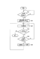
図1は、本実施形態に係る制御システムのブロック図である。図1において、ブロック間の実線は電力ラインを示し、ブロック間の破線は制御ラインを示す。なお、制御ラインは無線としてもよい。(1) Overall Configuration FIG. 1 is a block diagram of a control system according to this embodiment. In FIG. 1, the solid line between blocks shows a power line, and the broken line between blocks shows a control line. The control line may be wireless.
図1に示すように、本実施形態に係る制御システムは、系統電源1と、複数の蓄電池10と、分散型電源20と、1又は複数の負荷機器30と、分電盤40と、HEMS100と、を有する。複数の蓄電池10は、蓄電池群を構成する。
As shown in FIG. 1, the control system according to the present embodiment includes a system power supply 1, a plurality of
蓄電池10、分散型電源20、負荷機器30、分電盤40、及びHEMS100は、系統電源1から電力の供給を受ける需要家としての住宅Hに設けられる。
The
系統電源1は、電源の一例である。系統電源1は、電力会社によって管理されており、電力を住宅Hに供給する。系統電源1は、停電が生じない限り、安定した電力を常に住宅Hに供給できる。 The system power supply 1 is an example of a power supply. The system power supply 1 is managed by an electric power company and supplies electric power to the house H. The system power supply 1 can always supply stable power to the house H unless a power failure occurs.
一般的に、系統電源1から住宅Hに供給される電力の料金は、電力需要の少ない深夜においては、それ以外の時間帯に比べて安価に設定されている。 In general, the charge of power supplied from the system power supply 1 to the house H is set at a lower price than in other time zones at midnight when the power demand is low.
蓄電池10は、分電盤40を介して入力される電力によって充電される。蓄電池10は、放電を行うことによって、分電盤40を介して電力を負荷機器30に供給する。蓄電池10のそれぞれの充放電は、HEMS100によって制御される。
The
本実施形態では、蓄電池10は、同じ種別の蓄電池で統一されておらず、異なる種別の蓄電池が混在している。例えば、蓄電池10−1は補充電に適した種別の蓄電池であり、蓄電池10−2は補充電に適さない種別の蓄電池である。
In this embodiment, the
「補充電に適した種別の蓄電池」とは、蓄えた電力を完全に放電する前に充電(いわゆる、継ぎ足し充電)を行っても、メモリー効果などに起因する性能低下が生じ難い蓄電池である。このような蓄電池としては、例えばリチウムイオン電池などが挙げられる。 “A storage battery of a type suitable for supplementary charging” is a storage battery in which even if charging (so-called “additional charging”) is performed before the stored power is completely discharged, performance degradation due to the memory effect or the like hardly occurs. Examples of such a storage battery include a lithium ion battery.
これに対し、「補充電に適さない種別の蓄電池」とは、継ぎ足し充電を行うと、メモリー効果などに起因する性能低下が生じ易い蓄電池である。このような蓄電池としては、例えば、ニッケルカドニウム電池、ニッケル水素電池、及び鉛蓄電池などが挙げられる。 On the other hand, “a storage battery of a type that is not suitable for supplementary charging” is a storage battery that is susceptible to performance degradation due to the memory effect or the like when additional charging is performed. Examples of such a storage battery include a nickel cadmium battery, a nickel hydrogen battery, and a lead storage battery.
蓄電池10は、自身に関する情報(例えば、種別、使用日数、容量、充電回数、及び放電回数)を管理する機能を有していてもよい。
The
分散型電源20は、電源の一例である。ここで、分散型電源20は、発電を行うことによって、分電盤40を介して電力を負荷機器30及び/又は蓄電池10に供給する発電装置を意味する。分散型電源20は、発電量を制御可能な種別の分散型電源であってもよく、発電量を制御不能な種別の分散型電源であってもよい。
The
「発電量を制御可能な種別の分散型電源」とは、ガスなどを用いて発電を行う分散型電源であり、例えば、SOFC(Solid Oxide Fuel Cell)又はPEFC(Polymer Electrolyte Fuel Cell)等の燃料電池、及びガスタービン発電機などを含む。このような分散型電源には、通常、負荷機器30の消費電力の増減に応じて発電量を増減する負荷追従制御が適用される。ただし、このような分散型電源は、発電量を急速に変化させることはできず、負荷機器30の消費電力に対する過不足が生じ得る。
The “distributed power source of a type capable of controlling the power generation amount” is a distributed power source that generates power using gas or the like, for example, a fuel such as SOFC (Solid Oxide Fuel Cell) or PEFC (Polymer Electrolyte Fuel Cell). Includes batteries and gas turbine generators. For such a distributed power source, load follow-up control that increases or decreases the amount of power generation according to the increase or decrease in power consumption of the
これに対し、「発電量を制御不能な種別の分散型電源」とは、自然エネルギー(再生可能エネルギー)を用いて発電を行う分散型電源であり、例えば、太陽電池及び風力発電機などを含む。このような分散型電源は、発電した電力を系統電源1に逆潮流(いわゆる、売電)させることができる。ただし、このような分散型電源には負荷追従制御を適用できない。 On the other hand, “a distributed power source of a type whose power generation amount cannot be controlled” is a distributed power source that generates power using natural energy (renewable energy), and includes, for example, a solar cell and a wind power generator. . Such a distributed power source can cause the generated power to flow backward (so-called power sale) to the system power source 1. However, load following control cannot be applied to such a distributed power source.
負荷機器30は、分電盤40を介して入力される電力を消費して動作する。負荷機器30は、例えば住宅Hに設けられる家電機器(冷蔵庫、エアコン、及び照明など)である。
The
分電盤40は、系統電源1からの電力を負荷機器30及び蓄電池10に供給する。また、分電盤40は、蓄電池10からの電力を負荷機器30に供給したり、分散型電源20からの電力を負荷機器30及び蓄電池10に供給したりする。また、分散型電源20が、自然エネルギー(再生可能エネルギー)を用いて発電を行う分散型電源である場合は、分電盤40は、分散型電源20が発電した電力を系統電源1に逆潮流させてもよい。
The
分電盤40は、HEMS100の制御に応じて、内部の結線状態を変更する。例えば、分電盤40は、何れかの蓄電池10を分散型電源20と電気的に接続/切断したり、何れかの蓄電池10を系統電源1と電気的に接続/切断したりすることができる。
The
本実施形態では、分電盤40は、各種の電力を計測するためのセンサ41を含む。分電盤40は、センサ41が検知する電力の情報をHEMS100に通知する。センサ41は、例えば、系統電源1からの買電量、系統電源1に対する売電量、分散型電源20の発電量、及び蓄電池10の充放電電力量を検知する。
In the present embodiment, the
HEMS100は、蓄電池10、分散型電源20、負荷機器30、及び分電盤40のそれぞれと通信を行い、蓄電池10、分散型電源20、負荷機器30、及び分電盤40のそれぞれを制御する。以下において、HEMS100について説明する。
The
(2)HEMSの構成
図2は、HEMS100のブロック図である。(2) Configuration of HEMS FIG. 2 is a block diagram of the
図2に示すように、HEMS100は、表示部110と、入力部120と、通信部130と、記憶部140と、制御部150と、を有する。
As illustrated in FIG. 2, the
表示部110は、制御部150の制御下で、各種の表示を行う。入力部120は、ユーザからの入力を受け付けて、入力された内容を制御部150に出力する。表示部110及び入力部120は、タッチパネルとして一体化されていてもよい。
The
通信部130は、制御部150の制御下で、住宅Hに設けられた各機器(蓄電池10、分散型電源20、負荷機器30、及び分電盤40)との通信を行う。通信部130は、住宅Hに設けられた各機器との無線通信を行うためのZigbee(登録商標)モジュールであってもよい。
The
記憶部140は、制御部150による制御に使用される各種の情報を記憶する。また、記憶部140は、蓄電池10に関する情報(以下、「蓄電池情報」と称する)を記憶する。蓄電池情報は、蓄電池10の種別(例えば、リチウムイオン又は鉛)の情報を含む。また、蓄電池情報は、蓄電池10の劣化度(例えば、使用日数、充電回数、及び放電回数)の情報を含んでもよい。さらに、蓄電池情報は、蓄電池10の容量の情報を含んでもよい。
The
図3は、記憶部140が記憶する蓄電池情報の一例を示す。図3に示すように、蓄電池Aについての蓄電池情報として、種別“リチウムイオン”、使用日数“150日”、容量“2kWh”、充電回数“100回”、及び放電回数“120回”が記憶されている。他の蓄電池についても同様にこれらの情報が記憶されている。
FIG. 3 shows an example of storage battery information stored in the
制御部150は、情報取得部151と、情報管理部152と、スケジュール決定部153と、蓄電池制御部154と、を含む。
情報取得部151は、通信部130を用いて、蓄電池10の蓄電池情報を取得する。本実施形態では、情報取得部151は、蓄電池10が住宅Hに新たに設置された際に、当該新たに設置された蓄電池10の蓄電池情報を取得して、取得した蓄電池情報を記憶部140に記憶させる。
The
情報取得部151は、通信部130を用いて、新たに設置された蓄電池10との通信を行うことによって、当該新たに設置された蓄電池10の蓄電池情報を取得する。ここで、蓄電池10は、住宅Hに新たに設置され、HEMS100と接続された際に、Echonet Lite等の通信プロトコルに準拠したフォーマットで、自身の蓄電池情報を情報取得部151に送信してもよい。情報取得部151は、蓄電池10から蓄電池情報を受信した後、さらに必要な蓄電池情報の送信を、蓄電池10に要求してもよい。この場合、当該新たに設置された蓄電池10が自身の蓄電池情報を管理していることが前提となる。
The
新たに設置された蓄電池10が自身の蓄電池情報を管理していない場合、情報取得部151は、通信部130を用いて、新たに設置された蓄電池10の充放電特性を計測することによって、当該新たに設置された蓄電池10の蓄電池情報を取得する。例えば、情報取得部151は、通信部130を用いて新たに設置された蓄電池10に対して充放電を指示しつつ、センサ41により検知される充放電電力を周期的に取得することによって、当該新たに設置された蓄電池10の充放電特性を計測する。また、記憶部140には、蓄電池の種別毎の充放電特性パターンが予め記憶されており、情報取得部151は、蓄電池10について計測された充放電特性を各充放電特性パターンと比較することによって、当該蓄電池10の種別を推定する。さらに、各充放電特性パターンが劣化度別に分類されていれば、当該蓄電池10の劣化度も推定できる。
When the newly installed
情報管理部152は、記憶部140に記憶されている蓄電池10毎の蓄電池情報(図3参照)を管理する。例えば、情報管理部152は、蓄電池10毎に、日数の経過に応じて使用日数を更新し、充電の実施に応じて充電回数を更新し、放電の実施に応じて放電回数を更新する。
The
スケジュール決定部153は、情報管理部152が管理している蓄電池情報に基づいて、所定期間(例えば1日)毎に、各蓄電池10の充放電スケジュール(以下、適宜、単に「スケジュール」と称する)を決定する。充放電スケジュールとは、どの蓄電池10が、どの時間帯で、どのモードで充放電を行うかのスケジュールを意味する。蓄電池10の充放電のモードについては、後述する。
The
本実施形態では、スケジュール決定部153は、各蓄電池10の蓄電池情報に基づいて、複数の蓄電池10のそれぞれを、複数の電源(系統電源1及び分散型電源20)のそれぞれと対応付けて、スケジュールを決定する。
In the present embodiment, the
第1に、スケジュール決定部153は、補充電に適した種別の蓄電池10を分散型電源20と対応付けてスケジュールを決定する。上述したように、分散型電源20は、発電電力の過不足が頻繁に生じ得る。そこで、スケジュール決定部153は、補充電に適した種別の蓄電池10を分散型電源20と対応付け、当該過不足を相殺するように、スケジュールを決定する。その結果、系統電源1からの買電量を減らしたり、系統電源1への売電量を増やしたりすることができる。
First, the
第2に、スケジュール決定部153は、補充電に適さない種別の蓄電池10を系統電源1と対応付けてスケジュールを決定する。上述したように、系統電源1は、基本的には安定した電力を常に供給可能である。そこで、スケジュール決定部153は、補充電に適さない種別の蓄電池10を系統電源1と対応付け、当蓄電池10を満充電状態にした上で、当該蓄電池10から全ての電力を放電するように、スケジュールを決定する。その結果、例えば、深夜の安価な系統電力により当該蓄電池10を満充電状態とし、それ以外の時間帯で当該蓄電池10から全ての電力を放電できる。
Secondly, the
第3に、スケジュール決定部153は、蓄電池10それぞれの劣化度(例えば、使用日数、充電回数、及び放電回数)に応じて、蓄電池10毎に充放電の優先度を設定する。例えば、同じ種別の蓄電池10が複数個存在する場合において、劣化度の低い蓄電池10に対する優先度を“高”(メイン)とし、劣化度の高い蓄電池10に対する優先度を“低”(バックアップ)とする。その結果、これらの蓄電池10の劣化度を平準化することができ、蓄電池群の長寿命化を図ることができる。或いは、劣化度の低い蓄電池10に対する優先度を“低”(バックアップ)とし、劣化度の高い蓄電池10に対する優先度を“高”(メイン)とする。その結果、劣化の進行した蓄電池10を早期に使い切って交換することができ、蓄電池群の性能向上を図ることができる。
3rdly, the
蓄電池制御部154は、スケジュール決定部153により決定されたスケジュールに従って、各蓄電池10を制御する。詳細には、蓄電池制御部154は、通信部130を用いて、各蓄電池10に対して充放電の指示を送信したり、分電盤40に対して結線状態の変更指示を送信したりする。Lite又はZigBee等の通信プロトコルに準拠した信号を用いて、各種指示の送信を行う。
The storage
蓄電池制御部154は、蓄電池10の蓄電量及び負荷機器30の電力消費量に応じて、スケジュールの変更が必要になった場合には、スケジュールを適宜変更してもよい。
The storage
蓄電池制御部154は、充放電スケジュールの情報(図4参照)を表示するよう表示部110を制御してもよい。また、入力部120に対するユーザ入力に応じて、スケジュールを変更してもよい。
The storage
(3)HEMSの動作
以下において、HEMS100の動作を説明する。(3) Operation of HEMS The operation of the
(3.1)蓄電池情報取得動作
図4は、HEMS100における蓄電池情報取得動作の動作フロー図である。(3.1) Storage Battery Information Acquisition Operation FIG. 4 is an operation flowchart of the storage battery information acquisition operation in the
図4に示すように、ステップS11において、情報取得部151は、住宅Hに新たに設置された蓄電池10が検出されたか否かを確認する。新たに設置された蓄電池10が検出された場合(ステップS11;YES)、処理がステップS12に進む。
As shown in FIG. 4, in step S <b> 11, the
ステップS12において、情報取得部151は、新たに設置された蓄電池10から蓄電池情報を取得可能であるか否か、すなわち、当該蓄電池10が自身の蓄電池情報を管理しているか否かを確認する。新たに設置された蓄電池10から蓄電池情報を取得可能である場合(ステップS12;YES)、処理がステップS13に進む。これに対し、新たに設置された蓄電池10から蓄電池情報を取得不能である場合(ステップS12;NO)、処理がステップS14に進む。
In step S12, the
ステップS13において、情報取得部151は、新たに設置された蓄電池10から蓄電池情報を取得して、取得した蓄電池情報を記憶部140に記憶させる。
In step S <b> 13, the
一方、ステップS14において、情報取得部151は、新たに設置された蓄電池10の充放電特性を計測する。
On the other hand, in step S14, the
ステップS15において、情報取得部151は、ステップS14で計測された充放電特性に基づいて、新たに設置された蓄電池10の蓄電池情報を取得して、取得した蓄電池情報を記憶部140に記憶させる。
In step S15, the
(3.2)充放電制御動作
図5は、HEMS100における充放電制御動作の動作フロー図である。本動作フローは、例えば1日単位でスケジュールを決定するようなケースを想定している。(3.2) Charge / Discharge Control Operation FIG. 5 is an operation flowchart of the charge / discharge control operation in the
図5に示すように、ステップS21において、スケジュール決定部153は、現在の時刻がスケジュールを決定すべき時刻であるか否かを確認する。現在の時刻がスケジュールを決定すべき時刻である場合(ステップS21;YES)、処理がステップS22に進む。
As shown in FIG. 5, in step S21, the
ステップS22において、スケジュール決定部153は、記憶部140に記憶されている蓄電池10毎の蓄電池情報に基づいて、1日における時間帯別に、蓄電池10毎のスケジュールを決定する。スケジュールの具体例については後述する。
In step S <b> 22, the
ステップS23において、蓄電池制御部154は、その日のスケジュールに従って、各蓄電池10を制御する。
In step S23, the storage
ステップS24において、蓄電池制御部154は、その日のスケジュールが完了したか否かを確認する。その日のスケジュールが完了していない場合(ステップS24;NO)、処理がステップS25に進む。
In step S24, the storage
ステップS25において、蓄電池制御部154は、その日のスケジュールの変更が必要であるか否かを確認する。その日のスケジュールの変更が不要である場合(ステップS25;NO)、処理がステップS23に戻る。これに対し、その日のスケジュールの変更が必要である場合(ステップS25;YES)、処理がステップS26に進む。
In step S <b> 25, the storage
ステップS26において、蓄電池制御部154は、その日のスケジュールを変更する。その後、処理がステップS23に戻る。
In step S26, the storage
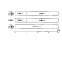
図6は、スケジュールの具体例を説明するための図である。ここでは、補充電に適した種別の蓄電池10としてリチウムイオン電池を例示し、補充電に適さない種別の蓄電池10として鉛蓄電池を例示している。また、劣化度の低いリチウムイオン電池Aと劣化度の高いリチウムイオン電池Bとが併存するケースを想定している。
FIG. 6 is a diagram for explaining a specific example of a schedule. Here, a lithium ion battery is illustrated as a type of
図6に示すように、スケジュール決定部153は、リチウムイオン電池Aを分散型電源20と対応付けてスケジュールを決定する。
As illustrated in FIG. 6, the
詳細には、スケジュール決定部153は、負荷機器30の電力消費量が少ない時間帯(深夜の時間帯)以外は、リチウムイオン電池Aを、分散型電源20の発電量の過不足を相殺するモード(相殺モード)で運用すると決定している。
More specifically, the
相殺モードにおいて、蓄電池制御部154は、分散型電源20の発電量が負荷機器30の電力消費量に対して不足するときは、当該不足分に相当する電力をリチウムイオン電池Aから放電するよう制御する。また、相殺モードにおいて、蓄電池制御部154は、分散型電源20の発電量が負荷機器30の電力消費量に対して超過するときは、当該超過分に相当する電力をリチウムイオン電池Aに充電するよう制御する。ここで、蓄電池制御部154は、例えばセンサ41の計測値から、分散型電源20の発電量と負荷機器30の電力消費量との差を把握し、リチウムイオン電池Aの充放電を制御する。
In the cancellation mode, the storage
一方、スケジュール決定部153は、負荷機器30の電力消費量が少ない時間帯(深夜の時間帯)は、リチウムイオン電池Aを、系統電力で充電するモード(充電モード)で運用すると決定している。
On the other hand, the
充電モードにおいて、蓄電池制御部154は、深夜の安価な系統電力をリチウムイオン電池Aに充電するよう制御する。ただし、相殺モードの終了時点で、リチウムイオン電池Aが満充電状態であれば、充電モードを中止してもよい。
In the charging mode, the storage
また、スケジュール決定部153は、鉛蓄電池を系統電源1と対応付けてスケジュールを決定する。
Further, the
詳細には、スケジュール決定部153は、負荷機器30の電力消費量が少ない時間帯(深夜の時間帯)において、系統電力により鉛蓄電池を満充電状態まで充電するモード(充電モード)で運用すると決定し、それ以外の時間帯において、鉛蓄電池から全ての電力を放電するモード(放電モード)で運用すると決定している。
Specifically, the
充電モードにおいて、蓄電池制御部154は、深夜の安価な系統電力を鉛蓄電池に充電するよう制御する。これに対し、放電モードにおいて、蓄電池制御部154は、分散型電源20の発電量が負荷機器30の電力消費量に対して不足するときに、当該不足分に相当する電力を鉛蓄電池から放電するよう制御する。リチウムイオン電池A及び鉛蓄電池の何れも放電可能なケースでは、鉛蓄電池の蓄電量をゼロにするために、鉛蓄電池から優先的に放電することが好ましい。
In the charging mode, the storage
さらに、スケジュール決定部153は、リチウムイオン電池Bを分散型電源20と対応付けてスケジュールを決定する。ここでは、スケジュール決定部153は、リチウムイオン電池Bの劣化度が高いことから、リチウムイオン電池Bに対する優先度を“低”(バックアップ)とするモード(バックアップモード)としている。
Furthermore, the
バックアップモードにおいて、蓄電池制御部154は、リチウムイオン電池Aのバックアップとしてリチウムイオン電池Bを使用するよう制御する。例えば、蓄電池制御部154は、リチウムイオン電池Aが満充電状態になった後は、リチウムイオン電池Aの代わりにリチウムイオン電池Bが充電を行うよう制御する。また、リチウムイオン電池Aの蓄電量が所定の下限値を下回った場合、又は、リチウムイオン電池Aに異常が生じた場合には、蓄電池制御部154は、リチウムイオン電池Aの代わりにリチウムイオン電池Bを相殺モードで運用するよう変更してもよい。
In the backup mode, the storage
(4)まとめ
以上説明したように、住宅に設けられる複数の蓄電池10を制御するHEMS100は、複数の蓄電池10それぞれの蓄電池情報に基づいて、複数の蓄電池10毎に充放電を制御する。これにより、複数の蓄電池10を効率的に制御できる。(4) Summary As described above, the
本実施形態では、HEMS100は、新たに設置された蓄電池10との通信を行うことによって、当該新たに設置された蓄電池10の蓄電池情報を取得する。或いは、HEMS100は、新たに設置された蓄電池10の充放電特性を計測することによって、当該新たに設置された蓄電池10の蓄電池情報を取得する。これにより、HEMS100が蓄電池情報を自動で取得できる。
In the present embodiment, the
本実施形態では、HEMS100は、補充電に適した種別の蓄電池10を分散型電源20と対応付けて制御する。これにより、分散型電源20の発電電力の過不足を相殺できる。その結果、系統電源1からの買電量を減らしたり、系統電源1への売電量を増やしたりすることができる。
In the present embodiment, the
本実施形態では、HEMS100は、補充電に適さない種別の蓄電池10を系統電源1と対応付けて制御する。これにより、深夜の安価な系統電力により当該蓄電池10を満充電状態とし、それ以外の時間帯で当該蓄電池10から全ての電力を放電できる。その結果、住宅Hにおける電気料金を低減できる。
In the present embodiment, the
本実施形態では、HEMS100は、複数の蓄電池10のそれぞれと複数の電源のそれぞれとの対応付けを、時間帯別に決定する。これにより、電気料金及び電力消費量を考慮して複数の蓄電池10を効率的に制御できる。
In the present embodiment, the
本実施形態では、HEMS100は、複数の蓄電池10それぞれの劣化度の情報に基づいて、複数の蓄電池10毎に充放電の優先度を設定する。これにより、蓄電池群の劣化度を平準化したり、蓄電池群の性能向上を図ったりすることができる。
In this embodiment, HEMS100 sets the priority of charging / discharging for every some
(5)その他の実施形態
上記のように、本発明は実施形態によって記載したが、この開示の一部をなす論述及び図面はこの発明を限定するものであると理解すべきではない。この開示から当業者には様々な代替実施形態、実施例及び運用技術が明らかとなる。(5) Other Embodiments As described above, the present invention has been described according to the embodiment. However, it should not be understood that the description and drawings constituting a part of this disclosure limit the present invention. From this disclosure, various alternative embodiments, examples and operational techniques will be apparent to those skilled in the art.
例えば、電気自動車に搭載されている蓄電池は、当該電気自動車が使用されていない状態においては、蓄電池群を構成する一つの蓄電池とみなすことができる。 For example, a storage battery mounted on an electric vehicle can be regarded as one storage battery constituting a storage battery group when the electric vehicle is not used.
また、上述した実施形態では、充電モードにおいて、蓄電池制御部154は、深夜の安価な系統電力を蓄電池10に充電するよう制御する。しかしながら、充電モードにおいて、蓄電池制御部154は、分散型電源20の発電電力を蓄電池10に充電するよう制御してもよい。
In the above-described embodiment, in the charging mode, the storage
また、上述した実施形態では、住宅単位で電力管理を行うための制御装置であるHEMS100を説明したが、ビルを対象としたBEMS(Building Energy Manegement System)、工場を対象としたFEMS(Factory Energy Manegement System)、又は地域を対象としたCEMS(Community Energy Management System)などであってもよい。
In the above-described embodiment, the
このように、本発明は、ここでは記載していない様々な実施の形態などを含むことは勿論である。また、上述した実施形態及び変更例は、組み合わせることが可能である。したがって、本発明の技術的範囲は、上述の説明から妥当な請求の範囲に係る発明特定事項によってのみ定められる。 As described above, the present invention naturally includes various embodiments that are not described herein. Further, the above-described embodiments and modification examples can be combined. Therefore, the technical scope of the present invention is determined only by the invention specifying matters according to the scope of claims reasonable from the above description.
なお、日本国特許出願第2012−040684号(2012年2月27日出願)の全内容が、参照により、本願に組み込まれている。 Note that the entire contents of Japanese Patent Application No. 2012-040684 (filed on Feb. 27, 2012) are incorporated herein by reference.
本発明によれば、需要家に設けられる複数の蓄電池を効率的に制御できる制御装置、制御システム及び蓄電池制御方法を提供できる。 ADVANTAGE OF THE INVENTION According to this invention, the control apparatus, control system, and storage battery control method which can control the some storage battery provided in a consumer efficiently can be provided.
Claims (13)
前記複数の蓄電池のそれぞれの種別及び/又は劣化度の情報を取得する取得部と、
前記複数の蓄電池のそれぞれの前記種別及び/又は劣化度の情報に基づいて、前記複数の蓄電池のそれぞれの充放電を制御する充放電制御部とを有しており、
前記充放電制御部は、前記複数の蓄電池が補充電に適した種別の第1蓄電池を含み、かつ、複数の電源が分散電源を含む場合に、前記第1蓄電池を前記分散電源と対応付けるとともに、前記第1蓄電池に適用する動作モードとして相殺モードをスケジュールとして決定し、
前記充放電制御部は、前記相殺モードにおいて、前記分散電源の発電量が負荷機器の電力消費量に対して超過するときに、前記分散電源から供給される電力によって前記第1蓄電池を充電するように制御するとともに、前記分散電源の発電量が前記負荷機器の電力消費量に対して不足するときに、前記第1蓄電池を放電するように制御し、
前記充放電制御部は、前記複数の蓄電池が補充電に適さない種別の第2蓄電池を含み、かつ、前記複数の電源が系統電源を含む場合に、前記第2蓄電池を前記系統電源と対応付けるとともに、前記第2蓄電池に適用する動作モードとして放電モードをスケジュールとして決定し、
前記充放電制御部は、前記放電モードにおいて、前記分散電源の発電量が前記負荷機器の電力消費量に対して超過するときであっても、前記分散電源から供給される電力によって前記第2蓄電池を充電しないように制御するとともに、前記分散電源の発電量が前記負荷機器の電力消費量に対して不足するときに、前記第1蓄電池を放電するように制御することを特徴とする制御装置。 A control device for controlling a plurality of storage batteries provided in an electric power consumer,
An acquisition unit for acquiring information on the type and / or deterioration level of each of the plurality of storage batteries;
A charge / discharge control unit for controlling charge / discharge of each of the plurality of storage batteries based on the information on the type and / or the degree of deterioration of each of the plurality of storage batteries;
The charge / discharge control unit includes a first storage battery of a type suitable for supplementary charging, and when the plurality of power supplies include a distributed power source , the first storage battery is associated with the distributed power source , The cancellation mode is determined as a schedule as an operation mode to be applied to the first storage battery,
The charge / discharge control unit charges the first storage battery with the power supplied from the distributed power supply when the power generation amount of the distributed power supply exceeds the power consumption of the load device in the cancellation mode. And controlling to discharge the first storage battery when the power generation amount of the distributed power supply is insufficient with respect to the power consumption of the load device,
The charging / discharging control unit includes a second storage battery of a type in which the plurality of storage batteries are not suitable for supplementary charging, and when the plurality of power supplies include a system power supply, the second storage battery is associated with the system power supply. The discharge mode is determined as a schedule as an operation mode to be applied to the second storage battery,
In the discharge mode, the charge / discharge control unit is configured to use the second storage battery by the power supplied from the distributed power supply even when the power generation amount of the distributed power supply exceeds the power consumption of the load device. And controlling so that the first storage battery is discharged when the power generation amount of the distributed power supply is insufficient with respect to the power consumption of the load device.
前記複数の蓄電池のそれぞれの種別及び/又は劣化度の情報を取得する取得部と、
前記複数の蓄電池のそれぞれの前記種別及び/又は劣化度の情報に基づいて、前記複数の蓄電池のそれぞれの充放電を制御する充放電制御部とを有しており、
前記充放電制御部は、前記複数の蓄電池が補充電に適した種別の第1蓄電池を含み、かつ、複数の電源が分散電源を含む場合に、前記第1蓄電池を前記分散電源と対応付けるとともに、前記第1蓄電池に適用する動作モードとして相殺モードをスケジュールとして決定し、
前記充放電制御部は、前記相殺モードにおいて、前記分散電源の発電量が負荷機器の電力消費量に対して超過するときに、前記分散電源から供給される電力によって前記第1蓄電池を充電するように制御するとともに、前記分散電源の発電量が前記負荷機器の電力消費量に対して不足するときに、前記第1蓄電池を放電するように制御し、
前記充放電制御部は、前記複数の蓄電池が補充電に適さない種別の第2蓄電池を含み、かつ、前記複数の電源が系統電源を含む場合に、前記第2蓄電池を前記系統電源と対応付けるとともに、前記第2蓄電池に適用する動作モードとして放電モードをスケジュールとして決定し、
前記充放電制御部は、前記放電モードにおいて、前記分散電源の発電量が前記負荷機器の電力消費量に対して超過するときであっても、前記分散電源から供給される電力によって前記第2蓄電池を充電しないように制御するとともに、前記分散電源の発電量が前記負荷機器の電力消費量に対して不足するときに、前記第1蓄電池を放電するように制御することを特徴とする制御システム。 A control system for controlling a plurality of storage batteries provided in a consumer of electric power,
An acquisition unit for acquiring information on the type and / or deterioration level of each of the plurality of storage batteries;
A charge / discharge control unit for controlling charge / discharge of each of the plurality of storage batteries based on the information on the type and / or the degree of deterioration of each of the plurality of storage batteries;
The charge / discharge control unit includes a first storage battery of a type suitable for supplementary charging, and when the plurality of power supplies include a distributed power source , the first storage battery is associated with the distributed power source , The cancellation mode is determined as a schedule as an operation mode to be applied to the first storage battery,
The charge / discharge control unit charges the first storage battery with the power supplied from the distributed power supply when the power generation amount of the distributed power supply exceeds the power consumption of the load device in the cancellation mode. And controlling to discharge the first storage battery when the power generation amount of the distributed power supply is insufficient with respect to the power consumption of the load device,
The charging / discharging control unit includes a second storage battery of a type in which the plurality of storage batteries are not suitable for supplementary charging, and when the plurality of power supplies include a system power supply, the second storage battery is associated with the system power supply. The discharge mode is determined as a schedule as an operation mode to be applied to the second storage battery,
In the discharge mode, the charge / discharge control unit is configured to use the second storage battery by the power supplied from the distributed power supply even when the power generation amount of the distributed power supply exceeds the power consumption of the load device. And controlling so that the first storage battery is discharged when the power generation amount of the distributed power supply is insufficient with respect to the power consumption of the load device.
前記複数の蓄電池のそれぞれの種別及び/又は劣化度の情報を取得するステップAと、
前記複数の蓄電池のそれぞれの前記種別及び/又は劣化度の情報に基づいて、前記複数の蓄電池のそれぞれの充放電を制御するステップBとを有しており、
前記ステップBは、前記複数の蓄電池が補充電に適した種別の第1蓄電池を含み、かつ、複数の電源が分散電源を含む場合に、前記第1蓄電池を前記分散電源と対応付けるとともに、前記第1蓄電池に適用する動作モードとして相殺モードをスケジュールとして決定するステップを含み、
前記相殺モードは、前記分散電源の発電量が負荷機器の電力消費量に対して超過するときに、前記分散電源から供給される電力によって前記第1蓄電池を充電するように制御するとともに、前記分散電源の発電量が前記負荷機器の電力消費量に対して不足するときに、前記第1蓄電池を放電するように制御するモードであり、
前記ステップBは、前記複数の蓄電池が補充電に適さない種別の第2蓄電池を含み、かつ、前記複数の電源が系統電源を含む場合に、前記第2蓄電池を前記系統電源と対応付けるとともに、前記第2蓄電池に適用する動作モードとして放電モードをスケジュールとして決定するステップを含み、
前記放電モードは、前記分散電源の発電量が前記負荷機器の電力消費量に対して超過するときであっても、前記分散電源から供給される電力によって前記第2蓄電池を充電しないように制御するとともに、前記分散電源の発電量が前記負荷機器の電力消費量に対して不足するときに、前記第1蓄電池を放電するように制御するモードであることを特徴とする蓄電池制御方法。 A storage battery control method applied to a control system for controlling a plurality of storage batteries provided in a power consumer,
Step A for obtaining information on the type and / or deterioration level of each of the plurality of storage batteries;
Step B for controlling charging / discharging of each of the plurality of storage batteries based on the information on the type and / or the degree of deterioration of each of the plurality of storage batteries,
The step B includes associating the first storage battery with the distributed power supply when the plurality of storage batteries include a first storage battery of a type suitable for supplementary charging and the plurality of power supplies include a distributed power supply . Determining a cancellation mode as a schedule as an operation mode applied to one storage battery,
The offset mode controls the first storage battery to be charged by the power supplied from the distributed power source when the power generation amount of the distributed power source exceeds the power consumption of the load device, and the distributed power source When the power generation amount of the power supply is insufficient with respect to the power consumption of the load device, it is a mode for controlling to discharge the first storage battery,
The step B includes a second storage battery of a type in which the plurality of storage batteries are not suitable for supplementary charging, and when the plurality of power supplies include a system power supply, the second storage battery is associated with the system power supply, and Determining a discharge mode as a schedule as an operation mode applied to the second storage battery;
The discharge mode is controlled so that the second storage battery is not charged by the power supplied from the distributed power supply even when the power generation amount of the distributed power supply exceeds the power consumption of the load device. In addition, the storage battery control method is a mode in which the first storage battery is controlled to be discharged when the power generation amount of the distributed power supply is insufficient with respect to the power consumption of the load device.
Priority Applications (1)
| Application Number | Priority Date | Filing Date | Title |
|---|---|---|---|
| JP2014502321A JP5890513B2 (en) | 2012-02-27 | 2013-02-27 | Control device, control system, and storage battery control method |
Applications Claiming Priority (4)
| Application Number | Priority Date | Filing Date | Title |
|---|---|---|---|
| JP2012040684 | 2012-02-27 | ||
| JP2012040684 | 2012-02-27 | ||
| JP2014502321A JP5890513B2 (en) | 2012-02-27 | 2013-02-27 | Control device, control system, and storage battery control method |
| PCT/JP2013/055195 WO2013129499A1 (en) | 2012-02-27 | 2013-02-27 | Control device, control system, and storage cell control method |
Related Child Applications (1)
| Application Number | Title | Priority Date | Filing Date |
|---|---|---|---|
| JP2016028617A Division JP2016123267A (en) | 2012-02-27 | 2016-02-18 | Control device, storage battery, and control method |
Publications (2)
| Publication Number | Publication Date |
|---|---|
| JPWO2013129499A1 JPWO2013129499A1 (en) | 2015-07-30 |
| JP5890513B2 true JP5890513B2 (en) | 2016-03-22 |
Family
ID=49082693
Family Applications (2)
| Application Number | Title | Priority Date | Filing Date |
|---|---|---|---|
| JP2014502321A Active JP5890513B2 (en) | 2012-02-27 | 2013-02-27 | Control device, control system, and storage battery control method |
| JP2016028617A Pending JP2016123267A (en) | 2012-02-27 | 2016-02-18 | Control device, storage battery, and control method |
Family Applications After (1)
| Application Number | Title | Priority Date | Filing Date |
|---|---|---|---|
| JP2016028617A Pending JP2016123267A (en) | 2012-02-27 | 2016-02-18 | Control device, storage battery, and control method |
Country Status (4)
| Country | Link |
|---|---|
| US (1) | US9735591B2 (en) |
| EP (1) | EP2822138B1 (en) |
| JP (2) | JP5890513B2 (en) |
| WO (1) | WO2013129499A1 (en) |
Families Citing this family (20)
| Publication number | Priority date | Publication date | Assignee | Title |
|---|---|---|---|---|
| WO2013125909A1 (en) * | 2012-02-23 | 2013-08-29 | 한국전력공사 | Device and method for scheduling power storage devices |
| CN104133540A (en) * | 2013-05-02 | 2014-11-05 | 鸿富锦精密工业(深圳)有限公司 | Power supply management system and method |
| WO2015100397A1 (en) * | 2013-12-26 | 2015-07-02 | Thermo King Corporation | Method and system for configuring a transport refrigeration unit battery charger for use in a transport refrigeration system |
| CN105874733B (en) * | 2013-12-26 | 2019-04-16 | 冷王公司 | Methods and systems for constructing battery chargers for transport refrigeration units for use in transport refrigeration systems |
| JP2015165732A (en) * | 2014-02-28 | 2015-09-17 | 株式会社Nttファシリティーズ | Storage battery control device, power supply system, storage battery control method and program |
| JP2015164378A (en) * | 2014-02-28 | 2015-09-10 | 株式会社Nttファシリティーズ | Storage battery control device, power supply system, storage battery control method, and program |
| US20160105044A1 (en) * | 2014-10-08 | 2016-04-14 | Panasonic Intellectual Property Management Co., Ltd. | Power-storage-system control method and power-storage-system control apparatus |
| KR102400501B1 (en) * | 2015-09-24 | 2022-05-20 | 삼성에스디아이 주식회사 | Uninterruptible power supply |
| JP6765995B2 (en) * | 2017-03-09 | 2020-10-07 | 株式会社ダイヘン | Wireless power management device, wireless power management method, and program |
| FR3068837B1 (en) * | 2017-07-07 | 2021-07-02 | Creatifs | UNIT FOR THE SUPPLY OF ELECTRIC, RECHARGEABLE AND CONNECTED ENERGY, PROCESS FOR ITS REALIZATION, AND ITS USE |
| JP2020188559A (en) * | 2019-05-13 | 2020-11-19 | 株式会社デンソー | Regional controller, building controller and energy management system |
| EP3991261A1 (en) * | 2019-06-27 | 2022-05-04 | Smart Power GmbH | Hybrid battery energy storage system |
| DE102020100008A1 (en) * | 2020-01-02 | 2021-07-08 | Innogy Se | Electrical supply system for a building |
| DE112021000960T5 (en) | 2020-03-27 | 2022-11-24 | Honda Motor Co., Ltd. | battery system |
| JP2022045569A (en) * | 2020-09-09 | 2022-03-22 | ヤマハ発動機株式会社 | Vessel propulsion system and power source system for vessel |
| JP7456408B2 (en) * | 2021-03-23 | 2024-03-27 | トヨタ自動車株式会社 | Battery management system and battery management method |
| JP7447854B2 (en) | 2021-03-23 | 2024-03-12 | トヨタ自動車株式会社 | Battery management system and battery management method |
| JP7494772B2 (en) | 2021-03-23 | 2024-06-04 | トヨタ自動車株式会社 | Battery management system and battery management method |
| JP7556314B2 (en) | 2021-03-23 | 2024-09-26 | トヨタ自動車株式会社 | Battery management system and battery management method |
| JP7797316B2 (en) * | 2022-06-21 | 2026-01-13 | 東芝エネルギーシステムズ株式会社 | Reverse flow power control device and reverse flow power control method |
Family Cites Families (42)
| Publication number | Priority date | Publication date | Assignee | Title |
|---|---|---|---|---|
| JPH08138749A (en) | 1994-11-16 | 1996-05-31 | Pfu Ltd | Battery control system |
| US5939861A (en) * | 1996-05-24 | 1999-08-17 | Hino Jidosha Kogyo Kabushiki Kaisha | Control system for on-vehicle battery |
| JP3641885B2 (en) * | 1996-11-12 | 2005-04-27 | 日産自動車株式会社 | Battery charging method and charging device |
| JPH10201120A (en) * | 1996-12-27 | 1998-07-31 | Canon Inc | Battery control method and device, and storage medium |
| JP3890168B2 (en) * | 1999-08-03 | 2007-03-07 | 株式会社東京アールアンドデー | Electric device and charging / discharging method of battery unit thereof |
| US6586940B2 (en) * | 2000-03-13 | 2003-07-01 | Nippon Telegraph And Telephone Corporation | Capacity estimation method, degradation estimation method and degradation estimation apparatus for lithium-ion cells, and lithium-ion batteries |
| JP2001309568A (en) * | 2000-04-26 | 2001-11-02 | Internatl Business Mach Corp <Ibm> | Charging system, charging control device, charging control method, and computer |
| TW535308B (en) * | 2000-05-23 | 2003-06-01 | Canon Kk | Detecting method for detecting internal state of a rechargeable battery, detecting device for practicing said detecting method, and instrument provided with said |
| JP3539412B2 (en) * | 2001-08-09 | 2004-07-07 | 日産自動車株式会社 | Battery battery abnormality detection device |
| JP3807965B2 (en) * | 2001-09-19 | 2006-08-09 | インターナショナル・ビジネス・マシーンズ・コーポレーション | Intelligent battery, electric device, computer device, and method for determining battery deterioration |
| US7385496B2 (en) * | 2002-04-15 | 2008-06-10 | Matsushita Electric Industrial Co., Ltd. | Monitoring system |
| US6850038B2 (en) * | 2002-05-14 | 2005-02-01 | Yazaki Corporation | Method of estimating state of charge and open circuit voltage of battery, and method and device for computing degradation degree of battery |
| WO2005015252A1 (en) * | 2003-06-27 | 2005-02-17 | The Furukawa Electric Co., Ltd. | Method for judging deterioration of accumulator, method for measuring secondary cell internal impedance, device for measuring secondary cell internal impedance, device for judging deterioration of secondary cell, and power source system |
| US7227335B2 (en) * | 2003-07-22 | 2007-06-05 | Makita Corporation | Method and apparatus for diagnosing the condition of a rechargeable battery |
| JP4445361B2 (en) * | 2004-09-24 | 2010-04-07 | 関西電力株式会社 | Power system control method and power system control apparatus using secondary battery |
| JP4572850B2 (en) * | 2006-03-24 | 2010-11-04 | 株式会社日立製作所 | Power control device |
| JP4265629B2 (en) * | 2006-08-01 | 2009-05-20 | トヨタ自動車株式会社 | Secondary battery charge / discharge control device and hybrid vehicle equipped with the same |
| JP2008067418A (en) | 2006-09-04 | 2008-03-21 | Nippon Telegr & Teleph Corp <Ntt> | Charging control method, power storage device and charging control system |
| JP2008151526A (en) * | 2006-12-14 | 2008-07-03 | Matsushita Electric Ind Co Ltd | Secondary battery deterioration judgment device and backup power source |
| JP2008228492A (en) * | 2007-03-14 | 2008-09-25 | Sanyo Electric Co Ltd | Method for charging lithium ion secondary battery |
| JP2008295172A (en) * | 2007-05-23 | 2008-12-04 | Canon Inc | Battery pack, charging device, and electronic device |
| US20100274508A1 (en) * | 2007-12-27 | 2010-10-28 | Kyocera Corporation | Mobile Electronic Device and Method for Controlling the Same |
| JP5106272B2 (en) * | 2008-06-30 | 2012-12-26 | パナソニック株式会社 | Degradation determination circuit, power supply device, and secondary battery deterioration determination method |
| JP4691140B2 (en) | 2008-07-15 | 2011-06-01 | レノボ・シンガポール・プライベート・リミテッド | Charge / discharge system and portable computer |
| KR100970841B1 (en) * | 2008-08-08 | 2010-07-16 | 주식회사 엘지화학 | Battery capacity deterioration estimation apparatus and method using battery voltage behavior |
| JP4649682B2 (en) * | 2008-09-02 | 2011-03-16 | 株式会社豊田中央研究所 | Secondary battery state estimation device |
| JP5310003B2 (en) * | 2009-01-07 | 2013-10-09 | 新神戸電機株式会社 | Lead storage battery control system for wind power generation |
| WO2010109956A1 (en) * | 2009-03-27 | 2010-09-30 | 株式会社日立製作所 | Electric storage device |
| JP4744622B2 (en) * | 2009-07-01 | 2011-08-10 | トヨタ自動車株式会社 | Vehicle control device |
| JP2011017203A (en) | 2009-07-09 | 2011-01-27 | Toyota Motor Corp | Building |
| KR101183751B1 (en) * | 2009-09-10 | 2012-09-17 | 가부시키가이샤 히다치 엔지니어링 서비스 | Power storage device of power generation system and operation method thereof |
| JP5586219B2 (en) * | 2009-12-25 | 2014-09-10 | 株式会社東芝 | Diagnostic device, battery pack, and battery value index manufacturing method |
| US9048514B2 (en) * | 2010-04-23 | 2015-06-02 | Psion Inc. | Replacement battery indicator on a battery powered device |
| JP5415359B2 (en) | 2010-05-31 | 2014-02-12 | 日立コンシューマエレクトロニクス株式会社 | Electrical device control system and electrical device controller |
| JP5467010B2 (en) * | 2010-07-22 | 2014-04-09 | ニチコン株式会社 | Learning-type storage battery management system |
| US20110125337A1 (en) * | 2010-08-30 | 2011-05-26 | Vyacheslav Zavadsky | Household appliance adapted to work with time of use electricity rates |
| WO2012032776A1 (en) * | 2010-09-10 | 2012-03-15 | パナソニック株式会社 | Power control device, power control method, and power supply system |
| JPWO2012091077A1 (en) * | 2010-12-28 | 2014-06-05 | 三洋電機株式会社 | How to detect battery deterioration |
| JP2012168728A (en) * | 2011-02-14 | 2012-09-06 | Mitsumi Electric Co Ltd | Protection module and state information management method in protection module |
| WO2013031394A1 (en) * | 2011-09-02 | 2013-03-07 | 日本電気株式会社 | Cell control system, cell control device, cell control method, and recording medium |
| JP5537521B2 (en) * | 2011-09-20 | 2014-07-02 | 株式会社日立製作所 | Lithium ion secondary battery control system and battery pack control system |
| JP5675727B2 (en) * | 2012-08-10 | 2015-02-25 | 株式会社東芝 | Charge / discharge instruction device, program |
-
2013
- 2013-02-27 EP EP13754672.7A patent/EP2822138B1/en active Active
- 2013-02-27 US US14/380,963 patent/US9735591B2/en active Active
- 2013-02-27 JP JP2014502321A patent/JP5890513B2/en active Active
- 2013-02-27 WO PCT/JP2013/055195 patent/WO2013129499A1/en not_active Ceased
-
2016
- 2016-02-18 JP JP2016028617A patent/JP2016123267A/en active Pending
Also Published As
| Publication number | Publication date |
|---|---|
| EP2822138A4 (en) | 2015-12-02 |
| EP2822138B1 (en) | 2018-11-07 |
| JPWO2013129499A1 (en) | 2015-07-30 |
| EP2822138A1 (en) | 2015-01-07 |
| JP2016123267A (en) | 2016-07-07 |
| US9735591B2 (en) | 2017-08-15 |
| US20150171641A1 (en) | 2015-06-18 |
| WO2013129499A1 (en) | 2013-09-06 |
Similar Documents
| Publication | Publication Date | Title |
|---|---|---|
| JP5890513B2 (en) | Control device, control system, and storage battery control method | |
| CN102709961B (en) | Charge/discharge determining device and method | |
| JP5841817B2 (en) | Power feeding system and method for controlling power feeding system | |
| JP6175514B2 (en) | POWER CONTROL DEVICE, DEVICE CONTROL DEVICE, AND METHOD | |
| US20140049053A1 (en) | Control device, power control system, and power control method | |
| JP5729764B2 (en) | Apartment house power system and control device | |
| JP6396531B2 (en) | POWER CONTROL DEVICE, DEVICE CONTROL DEVICE, AND METHOD | |
| JP2008182851A (en) | Power storage apparatus and system | |
| US20120249152A1 (en) | Charging/discharging determination apparatus and computer-readable non-transitory medium storing charging/discharging determination program | |
| JP2012123637A (en) | Charge controller, control method of charge controller, charge/discharge controller, control method of charge/discharge controller, control program, and recording medium | |
| US20120065801A1 (en) | Method and system for controlling a building load in tandem with a replenishable energy source in order to increase the apparent size of the replenishable energy source | |
| CN103703648A (en) | Power management system and management method | |
| JP6693545B2 (en) | Power management system, storage battery mounted device, EMS controller and power management server | |
| JP5592772B2 (en) | Power supply control device and power supply system using the same | |
| CN104541434A (en) | Management system, management method, control device, and power storage device | |
| US9846418B2 (en) | Energy control system, energy control device, and energy control method for prioritizing a power generation source based on the possibility of selling generated power | |
| KR20140137545A (en) | Smart switchgear having energy storage module | |
| JP2013038838A (en) | Collective housing power system | |
| US20160111880A1 (en) | Power controller, power control method, and power control system | |
| EP3718815A1 (en) | Electric power management system | |
| JP2025131711A (en) | Charging/discharging system, control method for charging/discharging system, and computer program | |
| JP2016126983A (en) | Fuel cell controller, fuel cell control system, fuel cell control method and computer program | |
| JP2013116033A (en) | Power supply device | |
| JP5456002B2 (en) | Electric vehicle charging / discharging system | |
| JP6523120B2 (en) | Power supply system |
Legal Events
| Date | Code | Title | Description |
|---|---|---|---|
| A131 | Notification of reasons for refusal |
Free format text: JAPANESE INTERMEDIATE CODE: A131 Effective date: 20150526 |
|
| A521 | Request for written amendment filed |
Free format text: JAPANESE INTERMEDIATE CODE: A523 Effective date: 20150727 |
|
| A131 | Notification of reasons for refusal |
Free format text: JAPANESE INTERMEDIATE CODE: A131 Effective date: 20150901 |
|
| A521 | Request for written amendment filed |
Free format text: JAPANESE INTERMEDIATE CODE: A523 Effective date: 20151029 |
|
| TRDD | Decision of grant or rejection written | ||
| A01 | Written decision to grant a patent or to grant a registration (utility model) |
Free format text: JAPANESE INTERMEDIATE CODE: A01 Effective date: 20160119 |
|
| A61 | First payment of annual fees (during grant procedure) |
Free format text: JAPANESE INTERMEDIATE CODE: A61 Effective date: 20160218 |
|
| R150 | Certificate of patent or registration of utility model |
Ref document number: 5890513 Country of ref document: JP Free format text: JAPANESE INTERMEDIATE CODE: R150 |