JP7140852B2 - Hybrid energy storage module system with auxiliary battery - Google Patents
Hybrid energy storage module system with auxiliary battery Download PDFInfo
- Publication number
- JP7140852B2 JP7140852B2 JP2020568454A JP2020568454A JP7140852B2 JP 7140852 B2 JP7140852 B2 JP 7140852B2 JP 2020568454 A JP2020568454 A JP 2020568454A JP 2020568454 A JP2020568454 A JP 2020568454A JP 7140852 B2 JP7140852 B2 JP 7140852B2
- Authority
- JP
- Japan
- Prior art keywords
- battery module
- energy storage
- sensing unit
- module
- switching network
- Prior art date
- Legal status (The legal status is an assumption and is not a legal conclusion. Google has not performed a legal analysis and makes no representation as to the accuracy of the status listed.)
- Active
Links
Images


Classifications
-
- H—ELECTRICITY
- H01—ELECTRIC ELEMENTS
- H01M—PROCESSES OR MEANS, e.g. BATTERIES, FOR THE DIRECT CONVERSION OF CHEMICAL ENERGY INTO ELECTRICAL ENERGY
- H01M16/00—Structural combinations of different types of electrochemical generators
-
- H—ELECTRICITY
- H01—ELECTRIC ELEMENTS
- H01M—PROCESSES OR MEANS, e.g. BATTERIES, FOR THE DIRECT CONVERSION OF CHEMICAL ENERGY INTO ELECTRICAL ENERGY
- H01M12/00—Hybrid cells; Manufacture thereof
- H01M12/02—Details
-
- B—PERFORMING OPERATIONS; TRANSPORTING
- B60—VEHICLES IN GENERAL
- B60L—PROPULSION OF ELECTRICALLY-PROPELLED VEHICLES; SUPPLYING ELECTRIC POWER FOR AUXILIARY EQUIPMENT OF ELECTRICALLY-PROPELLED VEHICLES; ELECTRODYNAMIC BRAKE SYSTEMS FOR VEHICLES IN GENERAL; MAGNETIC SUSPENSION OR LEVITATION FOR VEHICLES; MONITORING OPERATING VARIABLES OF ELECTRICALLY-PROPELLED VEHICLES; ELECTRIC SAFETY DEVICES FOR ELECTRICALLY-PROPELLED VEHICLES
- B60L58/00—Methods or circuit arrangements for monitoring or controlling batteries or fuel cells, specially adapted for electric vehicles
- B60L58/10—Methods or circuit arrangements for monitoring or controlling batteries or fuel cells, specially adapted for electric vehicles for monitoring or controlling batteries
- B60L58/18—Methods or circuit arrangements for monitoring or controlling batteries or fuel cells, specially adapted for electric vehicles for monitoring or controlling batteries of two or more battery modules
- B60L58/20—Methods or circuit arrangements for monitoring or controlling batteries or fuel cells, specially adapted for electric vehicles for monitoring or controlling batteries of two or more battery modules having different nominal voltages
-
- G—PHYSICS
- G01—MEASURING; TESTING
- G01R—MEASURING ELECTRIC VARIABLES; MEASURING MAGNETIC VARIABLES
- G01R31/00—Arrangements for testing electric properties; Arrangements for locating electric faults; Arrangements for electrical testing characterised by what is being tested not provided for elsewhere
- G01R31/36—Arrangements for testing, measuring or monitoring the electrical condition of accumulators or electric batteries, e.g. capacity or state of charge [SoC]
- G01R31/382—Arrangements for monitoring battery or accumulator variables, e.g. SoC
-
- H—ELECTRICITY
- H01—ELECTRIC ELEMENTS
- H01M—PROCESSES OR MEANS, e.g. BATTERIES, FOR THE DIRECT CONVERSION OF CHEMICAL ENERGY INTO ELECTRICAL ENERGY
- H01M10/00—Secondary cells; Manufacture thereof
- H01M10/05—Accumulators with non-aqueous electrolyte
- H01M10/052—Li-accumulators
-
- H—ELECTRICITY
- H01—ELECTRIC ELEMENTS
- H01M—PROCESSES OR MEANS, e.g. BATTERIES, FOR THE DIRECT CONVERSION OF CHEMICAL ENERGY INTO ELECTRICAL ENERGY
- H01M10/00—Secondary cells; Manufacture thereof
- H01M10/05—Accumulators with non-aqueous electrolyte
- H01M10/052—Li-accumulators
- H01M10/0525—Rocking-chair batteries, i.e. batteries with lithium insertion or intercalation in both electrodes; Lithium-ion batteries
-
- H—ELECTRICITY
- H01—ELECTRIC ELEMENTS
- H01M—PROCESSES OR MEANS, e.g. BATTERIES, FOR THE DIRECT CONVERSION OF CHEMICAL ENERGY INTO ELECTRICAL ENERGY
- H01M10/00—Secondary cells; Manufacture thereof
- H01M10/06—Lead-acid accumulators
-
- H—ELECTRICITY
- H01—ELECTRIC ELEMENTS
- H01M—PROCESSES OR MEANS, e.g. BATTERIES, FOR THE DIRECT CONVERSION OF CHEMICAL ENERGY INTO ELECTRICAL ENERGY
- H01M10/00—Secondary cells; Manufacture thereof
- H01M10/42—Methods or arrangements for servicing or maintenance of secondary cells or secondary half-cells
- H01M10/48—Accumulators combined with arrangements for measuring, testing or indicating the condition of cells, e.g. the level or density of the electrolyte
-
- H—ELECTRICITY
- H02—GENERATION; CONVERSION OR DISTRIBUTION OF ELECTRIC POWER
- H02J—CIRCUIT ARRANGEMENTS OR SYSTEMS FOR SUPPLYING OR DISTRIBUTING ELECTRIC POWER; SYSTEMS FOR STORING ELECTRIC ENERGY
- H02J1/00—Circuit arrangements for dc mains or dc distribution networks
- H02J1/10—Parallel operation of dc sources
-
- H—ELECTRICITY
- H02—GENERATION; CONVERSION OR DISTRIBUTION OF ELECTRIC POWER
- H02J—CIRCUIT ARRANGEMENTS OR SYSTEMS FOR SUPPLYING OR DISTRIBUTING ELECTRIC POWER; SYSTEMS FOR STORING ELECTRIC ENERGY
- H02J7/00—Circuit arrangements for charging or depolarising batteries or for supplying loads from batteries
- H02J7/0047—Circuit arrangements for charging or depolarising batteries or for supplying loads from batteries with monitoring or indicating devices or circuits
- H02J7/0048—Detection of remaining charge capacity or state of charge [SOC]
-
- H—ELECTRICITY
- H02—GENERATION; CONVERSION OR DISTRIBUTION OF ELECTRIC POWER
- H02J—CIRCUIT ARRANGEMENTS OR SYSTEMS FOR SUPPLYING OR DISTRIBUTING ELECTRIC POWER; SYSTEMS FOR STORING ELECTRIC ENERGY
- H02J7/00—Circuit arrangements for charging or depolarising batteries or for supplying loads from batteries
- H02J7/34—Parallel operation in networks using both storage and other dc sources, e.g. providing buffering
- H02J7/342—The other DC source being a battery actively interacting with the first one, i.e. battery to battery charging
-
- H—ELECTRICITY
- H02—GENERATION; CONVERSION OR DISTRIBUTION OF ELECTRIC POWER
- H02J—CIRCUIT ARRANGEMENTS OR SYSTEMS FOR SUPPLYING OR DISTRIBUTING ELECTRIC POWER; SYSTEMS FOR STORING ELECTRIC ENERGY
- H02J9/00—Circuit arrangements for emergency or stand-by power supply, e.g. for emergency lighting
- H02J9/04—Circuit arrangements for emergency or stand-by power supply, e.g. for emergency lighting in which the distribution system is disconnected from the normal source and connected to a standby source
- H02J9/06—Circuit arrangements for emergency or stand-by power supply, e.g. for emergency lighting in which the distribution system is disconnected from the normal source and connected to a standby source with automatic change-over, e.g. UPS systems
- H02J9/061—Circuit arrangements for emergency or stand-by power supply, e.g. for emergency lighting in which the distribution system is disconnected from the normal source and connected to a standby source with automatic change-over, e.g. UPS systems for DC powered loads
-
- H—ELECTRICITY
- H01—ELECTRIC ELEMENTS
- H01M—PROCESSES OR MEANS, e.g. BATTERIES, FOR THE DIRECT CONVERSION OF CHEMICAL ENERGY INTO ELECTRICAL ENERGY
- H01M2220/00—Batteries for particular applications
- H01M2220/20—Batteries in motive systems, e.g. vehicle, ship, plane
-
- H—ELECTRICITY
- H02—GENERATION; CONVERSION OR DISTRIBUTION OF ELECTRIC POWER
- H02J—CIRCUIT ARRANGEMENTS OR SYSTEMS FOR SUPPLYING OR DISTRIBUTING ELECTRIC POWER; SYSTEMS FOR STORING ELECTRIC ENERGY
- H02J2310/00—The network for supplying or distributing electric power characterised by its spatial reach or by the load
- H02J2310/40—The network being an on-board power network, i.e. within a vehicle
- H02J2310/48—The network being an on-board power network, i.e. within a vehicle for electric vehicles [EV] or hybrid vehicles [HEV]
-
- Y—GENERAL TAGGING OF NEW TECHNOLOGICAL DEVELOPMENTS; GENERAL TAGGING OF CROSS-SECTIONAL TECHNOLOGIES SPANNING OVER SEVERAL SECTIONS OF THE IPC; TECHNICAL SUBJECTS COVERED BY FORMER USPC CROSS-REFERENCE ART COLLECTIONS [XRACs] AND DIGESTS
- Y02—TECHNOLOGIES OR APPLICATIONS FOR MITIGATION OR ADAPTATION AGAINST CLIMATE CHANGE
- Y02E—REDUCTION OF GREENHOUSE GAS [GHG] EMISSIONS, RELATED TO ENERGY GENERATION, TRANSMISSION OR DISTRIBUTION
- Y02E60/00—Enabling technologies; Technologies with a potential or indirect contribution to GHG emissions mitigation
- Y02E60/10—Energy storage using batteries
-
- Y—GENERAL TAGGING OF NEW TECHNOLOGICAL DEVELOPMENTS; GENERAL TAGGING OF CROSS-SECTIONAL TECHNOLOGIES SPANNING OVER SEVERAL SECTIONS OF THE IPC; TECHNICAL SUBJECTS COVERED BY FORMER USPC CROSS-REFERENCE ART COLLECTIONS [XRACs] AND DIGESTS
- Y02—TECHNOLOGIES OR APPLICATIONS FOR MITIGATION OR ADAPTATION AGAINST CLIMATE CHANGE
- Y02T—CLIMATE CHANGE MITIGATION TECHNOLOGIES RELATED TO TRANSPORTATION
- Y02T10/00—Road transport of goods or passengers
- Y02T10/60—Other road transportation technologies with climate change mitigation effect
- Y02T10/70—Energy storage systems for electromobility, e.g. batteries
Landscapes
- Engineering & Computer Science (AREA)
- Power Engineering (AREA)
- Chemical & Material Sciences (AREA)
- General Chemical & Material Sciences (AREA)
- Electrochemistry (AREA)
- Chemical Kinetics & Catalysis (AREA)
- Manufacturing & Machinery (AREA)
- Physics & Mathematics (AREA)
- Business, Economics & Management (AREA)
- Emergency Management (AREA)
- General Physics & Mathematics (AREA)
- Mechanical Engineering (AREA)
- Transportation (AREA)
- Sustainable Energy (AREA)
- Sustainable Development (AREA)
- Materials Engineering (AREA)
- Life Sciences & Earth Sciences (AREA)
- Secondary Cells (AREA)
- Electric Propulsion And Braking For Vehicles (AREA)
- Charge And Discharge Circuits For Batteries Or The Like (AREA)
Description
本発明は、エネルギー貯蔵モジュールシステムに関し、さらに詳細には、主バッテリーとは特性が異なるリチウム電池などの補助バッテリーで鉛蓄電池などの主バッテリーを補完して、負荷に要求される電力量の変化に応じて適切に対応することができるハイブリッドエネルギー貯蔵モジュールシステムに関する。 The present invention relates to energy storage module systems, and more particularly, to supplementing a main battery, such as a lead-acid battery, with an auxiliary battery, such as a lithium battery, having characteristics different from those of the main battery, to respond to changes in the amount of power demanded by the load. The present invention relates to a hybrid energy storage module system that can respond appropriately according to circumstances.
エネルギー貯蔵システムは、残った電力を別に貯蔵し、必要な時期に供給するシステムである。エネルギー貯蔵システムは、貯蔵方式によって物理的エネルギー貯蔵システムと化学的エネルギー貯蔵システムに大別される。代表的な物理的エネルギー貯蔵システムとしては、揚水発電システムや圧縮空気貯蔵システム、フライホイールなどを挙げることができ、化学的エネルギー貯蔵システムとしては、リチウム電池、鉛蓄電池、NaS電池などを挙げることができる。 An energy storage system is a system that stores remaining power separately and supplies it when needed. Energy storage systems are roughly classified into physical energy storage systems and chemical energy storage systems according to storage methods. Typical physical energy storage systems include pumped storage systems, compressed air storage systems, flywheels, etc. Chemical energy storage systems include lithium batteries, lead-acid batteries, NaS batteries, and the like. can.
夜間に捨てられる電気などをエネルギー貯蔵システムに貯蔵してピーク時間帯に使用すると電力需給問題を解決することができるという点で、エネルギー貯蔵システムに関する研究が盛んに行われている。 2. Description of the Related Art Energy storage systems have been extensively researched in that electricity that is wasted at night can be stored in an energy storage system and used during peak hours to solve the problem of power supply and demand.
小規模なエネルギー貯蔵システムの一例として、電気自動車のバッテリーがある。電気自動車は、モータを用いて駆動される自動車であって、大容量のバッテリーが装着される。このようなバッテリーとして、過去は鉛蓄電池が使用されたが、現在はニッケル水素電池やリチウム電池などが主に使用されており、向後はリチウム電池が主に使用されるものと予想される。 An example of a small-scale energy storage system is an electric vehicle battery. An electric vehicle is a vehicle that is driven by a motor and is equipped with a large-capacity battery. In the past, lead-acid batteries were used as such batteries, but at present, nickel-metal hydride batteries and lithium batteries are mainly used, and lithium batteries are expected to be mainly used in the future.
過去に使用された鉛蓄電池は、価格が相対的に非常に安く、高い信頼性を有するという利点があるが、単位重量当たりの出力が低く、体積が大きく、長時間使用すると出力電圧が低下し、放電率が低いため、高出力が要求される負荷によく露出される場合には過熱により寿命が短くなるという問題があって、電気自動車には優先的に選択されず、使用が忌避されている。また、回生制動によって回収された電気エネルギーの充電に適さないという問題もあった。 The lead-acid batteries used in the past have the advantages of relatively low price and high reliability, but the output per unit weight is low, the volume is large, and the output voltage drops after long-term use. However, due to its low discharge rate, it has a problem of shortening its life due to overheating when it is frequently exposed to loads that require high output. there is There is also the problem that it is not suitable for charging the electric energy recovered by regenerative braking.
リチウム電池は、他の電池に比べて高出力、高密度電池として脚光を浴びている。しかし、リチウム電池は、価格が非常に高く、温度によってパフォーマンスが大きく左右され、特に高温では、電解質分解が起こり、これにより寿命が著しく短縮する。さらに、発火及び爆発の危険もある。かかる問題点を改善するために、韓国公開特許第2010-0001877号公報、同第2003-0100891号公報、同第2003-0100893号公報などには、バッテリーを冷却するための方法が開示されている。 Lithium batteries are attracting attention as high power and high density batteries compared to other batteries. However, lithium batteries are very expensive and their performance is highly dependent on temperature, especially at high temperatures, where electrolyte decomposition occurs, which significantly shortens their lifespan. Furthermore, there is also the danger of ignition and explosion. In order to solve this problem, Korean Patent Publication Nos. 2010-0001877, 2003-0100891, and 2003-0100893 disclose methods for cooling the battery. .
現在使用される鉛蓄電池は、10kg当たり1kWh程度の電気エネルギーを貯蔵することができ、1kWh程度の電気エネルギーで電気自動車の場合は5~10kmを走行することができる。したがって、現在の自動車の走行距離である700km程度を走行するためには、高密度の鉛蓄電池を使用しても、1トン程度の鉛蓄電池が必要である。よって、鉛蓄電池などの低密度の二次電池をバッテリーとして使用することができない。 A currently used lead-acid battery can store electric energy of about 1 kWh per 10 kg, and an electric vehicle can run 5 to 10 km with about 1 kWh of electric energy. Therefore, in order to drive a current automobile for a distance of about 700 km, a lead-acid battery of about 1 ton is required even if a high-density lead-acid battery is used. Therefore, a low-density secondary battery such as a lead-acid battery cannot be used as a battery.
しかし、1回の充電で100km程度の走行が可能な電気自動車は、走行距離が短いので、必ず高密度電池を使用する必要がない。むしろ低コストの鉛蓄電池を使用することができれば、コストが削減され、発火及び爆発の危険がないため、冷却のための複雑な構造が必要ないという利点がある。また、電池を配置するときに発火や爆発の危険性を考慮する必要がないので、より自由に電池を配置することができるという利点もある。 However, an electric vehicle that can run about 100 km on a single charge does not need to use a high-density battery because the mileage is short. Rather, if a low-cost lead-acid battery can be used, there is an advantage that the cost is reduced, there is no risk of fire and explosion, and a complicated structure for cooling is not required. In addition, since there is no need to consider the risk of fire or explosion when arranging the batteries, there is also the advantage that the batteries can be arranged more freely.
しかし、上述したように、鉛蓄電池は、長時間使用すると、出力電圧が低くなって走行が難しく、リチウム電池に比べて出力が低いため停止後に出発するか或いは坂道を走行する場合のように高出力が要求される場合に対応し難く、高い放電率が要求される負荷によく露出される場合に寿命が短くなるという問題がある。また、鉛蓄電池は、回生制動による電気エネルギーの充電に活用され難いという問題がある。 However, as described above, when the lead-acid battery is used for a long time, the output voltage of the lead-acid battery becomes low, making it difficult to drive. There is a problem that it is difficult to respond when the output is required, and the life is shortened when frequently exposed to a load requiring a high discharge rate. In addition, lead-acid batteries have the problem that they are difficult to use for recharging electrical energy by regenerative braking.
また、互いに異なる種類の電池を交互に使用する従来のハイブリッド電池システムは、使用される電池の種類の変化に応じてエネルギー量が急激に変化するため、乗客やユーザーがその変化に応じた衝撃を感じることができるという問題点があった。また、エネルギー効率も落ちるという問題点があった。 In addition, in conventional hybrid battery systems that alternately use different types of batteries, the amount of energy changes abruptly in response to changes in the types of batteries used, so passengers and users experience shocks in response to these changes. The problem was that I could feel it. Moreover, there was a problem that the energy efficiency also fell.
また、ハイブリッド電池システムを搭載したプラグインハイブリッド車で走行と同時に充電が必要な場合、レンジエクステンダ(range extender)を駆動させてリチウム電池に充電をし、電気自動車の運行には鉛蓄電池を使用することにより、必要以上の大容量のリチウム電池を備えて充電しなければならないという問題があった。 Also, when a plug-in hybrid vehicle equipped with a hybrid battery system needs to be charged while running, a range extender is driven to charge the lithium battery, and a lead-acid battery is used to operate the electric vehicle. As a result, there is a problem that a lithium battery with a larger capacity than necessary must be prepared and charged.
本発明の目的は、高出力の要求に対応可能である、信頼性の高いハイブリッドエネルギー貯蔵モジュールシステムを提供することにある。例えば、一回の充電で100kmほどの走行が可能なエネルギー貯蔵モジュールシステムとして信頼性が高く、価格が非常に低い電気自動車用ハイブリッドエネルギー貯蔵モジュールシステムを提供することにある。 SUMMARY OF THE INVENTION It is an object of the present invention to provide a reliable hybrid energy storage module system capable of meeting high power demands. For example, it is an object of the present invention to provide a hybrid energy storage module system for an electric vehicle, which is highly reliable as an energy storage module system capable of traveling about 100 km on a single charge, and which is very inexpensive.
上記目的を達成するために、本発明は、負荷の駆動に必要な電力を供給するエネルギー貯蔵モジュールシステムであって、
第2電池モジュールと、前記第2電池モジュールに比べて放電率が高い第1電池モジュールと、前記第2電池モジュールに前記第1電池モジュールを並列に接続または分離するように構成されたスイッチングネットワークとを含み、前記負荷に接続されて電力を供給するように構成されたエネルギー貯蔵装置;
前記第1電池モジュールの状態を示すデータを測定するように構成された第1検知ユニット;
前記第2電池モジュールの状態を示すデータを測定するように構成された第2検知ユニット;及び
前記第1検知ユニットと前記第2検知ユニットからのデータを受信し、前記スイッチングネットワークを制御する制御信号を生成し、前記制御信号を前記スイッチングネットワークに送信する制御器;を含み、
前記制御器は、前記第1電池モジュールが前記第2電池モジュールに接続される前に前記第2電池モジュールが先に負荷に接続されるように前記スイッチングネットワークを制御する制御信号を生成し、
前記制御器は、前記第1検知ユニットと前記第2検知ユニットから受信したデータに基づいて、前記第2電池モジュールに対して前記第1電池モジュールが選択的に接続または分離されるように前記スイッチングネットワークを制御する制御信号を生成する、ハイブリッドエネルギー貯蔵モジュールシステムを提供する。
To achieve the above objects, the present invention provides an energy storage module system for supplying power required to drive a load, comprising:
a second battery module, a first battery module having a higher discharge rate than the second battery module, and a switching network configured to connect or disconnect the first battery module in parallel with the second battery module. an energy storage device configured to be connected to and power the load, comprising:
a first sensing unit configured to measure data indicative of the state of the first battery module;
a second sensing unit configured to measure data indicative of the state of the second battery module; and a control signal for receiving data from the first sensing unit and the second sensing unit and controlling the switching network. and sending said control signal to said switching network;
The controller generates a control signal to control the switching network such that the second battery module is first connected to a load before the first battery module is connected to the second battery module;
The controller controls the switching to selectively connect or disconnect the first battery module with respect to the second battery module based on data received from the first sensing unit and the second sensing unit. A hybrid energy storage module system is provided that generates control signals to control a network.
また、前記エネルギー貯蔵装置は、電流制限回路をさらに含み、前記スイッチングネットワークは、前記電流制限回路を前記第1電池モジュール又は前記第2電池モジュールに対して選択的に接続または分離するように構成され、前記制御器は、前記第1検知ユニットと前記第2検知ユニットから受信したデータに基づいて、前記第1電池モジュールに前記第2電池モジュールを接続する前に前記第1電池モジュール又は前記第2電池モジュールと前記電流制限回路とを接続するように前記スイッチングネットワークを制御する制御信号を生成することを特徴とする。 Also, the energy storage device further includes a current limiting circuit, and the switching network is configured to selectively connect or disconnect the current limiting circuit to the first battery module or the second battery module. , the controller, based on the data received from the first sensing unit and the second sensing unit, selects the first battery module or the second battery module before connecting the second battery module to the first battery module; A control signal is generated for controlling the switching network to connect the battery module and the current limiting circuit.
また、前記制御器は、前記第1電池モジュールが前記第2電池モジュールから分離された後に前記第2電池モジュールが負荷から分離されるように前記スイッチングネットワークを制御する制御信号を生成することを特徴とする。 Also, the controller generates a control signal for controlling the switching network such that the second battery module is isolated from the load after the first battery module is isolated from the second battery module. and
また、前記制御器は、回生制動による充電の際に、前記第1電池モジュールが前記第2電池モジュールから分離された後に前記第1電池モジュールが充電されるように前記スイッチングネットワークを制御する制御信号を生成することを特徴とする。 In addition, the controller controls the switching network to charge the first battery module after the first battery module is separated from the second battery module during charging by regenerative braking. is characterized by generating
また、前記制御器は、前記第2検知ユニットから受信した前記第2電池モジュールの出力端に流れる電流値の大きさと電流値の傾きが所定の値以上であれば、前記第2電池モジュールに前記第1電池モジュールが接続されるように前記スイッチングネットワークを制御する制御信号を生成することを特徴とする。 Further, if the magnitude of the current flowing through the output end of the second battery module and the slope of the current received from the second detection unit are equal to or greater than a predetermined value, the controller controls the detection of the second battery module. A control signal is generated to control the switching network so that the first battery module is connected.
また、前記スイッチングネットワークには、前記第1電池モジュールから前記第2電池モジュールに電流が流れることを防止する第1ダイオード、及び前記第2電池モジュールから前記第1電池モジュールに電流が流れることを防止する第2ダイオードが設置されたことを特徴とする。 The switching network includes a first diode that prevents current from flowing from the first battery module to the second battery module, and a diode that prevents current from flowing from the second battery module to the first battery module. characterized in that a second diode is installed.
また、前記スイッチングネットワークは、前記第2電池モジュールと前記第1電池モジュールと前記電流制限回路とを互いに並列に接続するネットワークに設置されたスイッチを含むことを特徴とする。 The switching network may include a switch installed in a network connecting the second battery module, the first battery module and the current limiting circuit in parallel.
また、前記第1電池モジュールは、リチウム電池モジュールであることを特徴とする。 Also, the first battery module is a lithium battery module.
また、前記リチウム電池モジュールは、リチウムポリマー電池、リチウムマンガン電池、リチウム鉄電池、リチウムイオン電池及びリチウム空気電池の中から選択されることを特徴とする。 Also, the lithium battery module is selected from a lithium polymer battery, a lithium manganese battery, a lithium iron battery, a lithium ion battery, and a lithium air battery.
また、前記第2電池モジュールは、鉛蓄電池モジュールであることを特徴とする。 Also, the second battery module is characterized by being a lead-acid battery module.
また、前記電流制限回路は、可変抵抗であることを特徴とする。 Also, the current limiting circuit is a variable resistor.
本発明に係るハイブリッドエネルギー貯蔵モジュールシステムは、リチウム電池モジュールなどの補助バッテリーを介して高出力の要求に対応可能であるうえ、信頼性が高いという利点がある。 The hybrid energy storage module system according to the present invention has the advantage of being able to meet high power requirements through auxiliary batteries such as lithium battery modules, as well as being highly reliable.
また、価格が低い鉛蓄電池モジュールを主バッテリーとして使用するので、製造コストが節減される。 In addition, since the lead-acid battery module, which is inexpensive, is used as the main battery, manufacturing costs are reduced.
また、従来のハイブリッドバッテリーシステムに比べて小さい容量の補助バッテリーの使用が可能なので、これによるコスト削減効果が大きい。 In addition, since it is possible to use an auxiliary battery with a smaller capacity than the conventional hybrid battery system, the cost reduction effect is great.
また、リチウム電池の継続的な使用によってリチウム電池の温度が上昇することを防止するための別途の冷却システムの必要性が低いので、システムの構造が簡単である。また、鉛蓄電池は、かなり安定的なので、リチウム電池のみ搭乗者の安全を考慮して安全な位置に設置すればよいので、電気自動車に配置することが容易である。 In addition, since the need for a separate cooling system to prevent the temperature of the lithium battery from rising due to continuous use of the lithium battery is low, the structure of the system is simple. In addition, since the lead-acid battery is fairly stable, only the lithium battery needs to be installed in a safe position in consideration of the safety of the passenger, so it is easy to install in the electric vehicle.
以下、添付図面を参照して、本発明の一実施形態について詳細に説明する。 An embodiment of the present invention will be described in detail below with reference to the accompanying drawings.
次に紹介される実施形態は、当業者に本発明の思想が十分に伝達できるようにするために例として提供されるものである。したがって、本発明は、以下に説明される実施形態に限定されず、他の形態に具体化されてもよい。そして、図面において、構成要素の幅、長さ、厚さなどは、便宜のために誇張して表現されることもある。明細書全体にわたって、同じ参照番号は同じ構成要素を示す。 The embodiments introduced next are provided as examples so as to fully convey the idea of the present invention to those skilled in the art. Accordingly, the present invention is not limited to the embodiments set forth below, but may be embodied in other forms. In the drawings, widths, lengths, thicknesses, etc. of components may be exaggerated for convenience. Like numbers refer to like elements throughout the specification.
本発明のハイブリッドエネルギー貯蔵モジュールシステムは、様々な用途に使用できるが、以下では、電気自動車に使用される場合を例として説明する。電気自動車には、ハイブリッド車(HEV)、プラグインハイブリッド車(PHEV)、純粋な電気自動車(EV)などが含まれる。そして、電気自動車には、乗用車、バン、バスだけでなく、スクーターやバイクなどの二輪自動車、車椅子、電動フォークリフト、清掃車、電動自転車などもすべて含まれる。以下では、純粋な電気自動車を例に挙げて説明する。 Although the hybrid energy storage module system of the present invention can be used for various purposes, the case where it is used for an electric vehicle will be described below as an example. Electric vehicles include hybrid vehicles (HEV), plug-in hybrid vehicles (PHEV), pure electric vehicles (EV), and the like. Electric vehicles include not only passenger cars, vans, and buses, but also two-wheel vehicles such as scooters and motorcycles, wheelchairs, electric forklifts, cleaning trucks, and electric bicycles. A purely electric vehicle will be taken as an example below.
図1は電気自動車システムの構成図である。図1を参照すると、電気自動車は、モータ1、モータコントローラ2、ハイブリッドエネルギー貯蔵モジュールシステム10、減速ギア3及び回生制動システム7を含む。
FIG. 1 is a configuration diagram of an electric vehicle system. Referring to FIG. 1, an electric vehicle includes a motor 1, a
電気自動車のモータ1は、モータジェネレータとも呼ばれる。運行中にブレーキを踏んだとき、モータ1を発電機にしてハイブリッドエネルギー貯蔵モジュールシステム10のリチウム電池モジュールや鉛蓄電池モジュールなどのエネルギー貯蔵装置を充電するからである。これを回生制動という。モータ1は、減速ギア3を介して車輪4に連結される。
The motor 1 of the electric vehicle is also called a motor generator. This is because the motor 1 is used as a generator to charge an energy storage device such as a lithium battery module or a lead-acid battery module of the hybrid energy
モータコントローラ2は、モータ制御器と、モータ制御器の命令に応じてモータ1を駆動するためにバッテリーの直流を三相交流に変換するインバータと、を含む。インバータは、パワートランジスタをオン/オフ(On-Off)にする方式で直流を交流に変換する。
The
ハイブリッドエネルギー貯蔵モジュールシステム10のエネルギー貯蔵装置20は、一般な自動車用ガソリンスタンドと同様の急速充電ステーションで充電するときに使用される急速充電具5と、家庭で使用される一般電源を介して充電することができる一般充電器6を介して充電できる。また、エネルギー貯蔵装置20は回生制動システム7によって充電されることも可能である。
The
図2は本発明の一実施形態に係るハイブリッドエネルギー貯蔵モジュールシステムのブロック図である。図2を参照すると、ハイブリッドエネルギー貯蔵モジュールシステム10は、エネルギー貯蔵装置20、第1検知ユニット21、第2検知ユニット22、及び制御器30を含む。
FIG. 2 is a block diagram of a hybrid energy storage module system according to one embodiment of the invention. Referring to FIG. 2, the hybrid energy
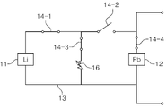
図3は図2に示されたエネルギー貯蔵装置のブロック図である。図3を参照すると、エネルギー貯蔵装置20は、第1電池モジュール、第2電池モジュール、電流制限回路、及びスイッチングネットワーク15を含む。
FIG. 3 is a block diagram of the energy storage device shown in FIG. 2; Referring to FIG. 3 , the
第1電池モジュールは、高出力が要求されるときに第2電池モジュールを補助するためのものであって、第2電池モジュールに比べて放電率がさらに高い。例えば、第1電池モジュールはリチウム電池モジュール11であり、第2電池モジュールは鉛蓄電池モジュール12であり得る。電流制限回路としては可変抵抗16を使用することができる。
The first battery module supports the second battery module when high power is required, and has a higher discharge rate than the second battery module. For example, the first battery module can be a
エネルギー貯蔵装置20は、負荷の両端に接続され、負荷であるモータ1に必要な電力を供給する役割を果たす。スイッチングネットワーク15は、リチウム電池モジュール11、鉛蓄電池モジュール12及び可変抵抗16を互いに並列に接続する導線13と、導線13に設置され、選択的に導線13を接続または遮断する複数のスイッチ14-1~14-4と、を含む。
The
リチウム電池モジュール11は、直・並列に接続された多数のリチウム電池セル(図示せず)を含む。電池の性能は、集められる電気エネルギー(単位はkWh)の大きさと、1時間でバッテリー容量の幾倍を放電することができるかを示す放電率(C-rate)などで表すことができる。リチウム電池は、鉛蓄電池に比べて単位重量あたり多くの電気エネルギーを貯蔵することができ、充放電速度も速い。しかし、リチウム電池は、温度が上昇すると特性が劣化し、爆発の危険性があり、価格が非常に高いという問題がある。本発明において、リチウム電池は、負極に金属リチウムを使用する二次電池であって、リチウムポリマー電池、リチウムマンガン電池、リチウム鉄電池、リチウムイオン電池及びリチウム空気電池などをすべて含む。また、現在開発されている、或いは今後開発されるリチウム二次電池も使用できる。
The
鉛蓄電池モジュール12は、直・並列に接続された多数の鉛蓄電池セル(図示せず)を含む。鉛蓄電池は、集められる電気エネルギーの大きさが小さく、単位時間当たり放電することが可能な電力の大きさも小さいが、価格が低く、爆発の危険性などがない安全なバッテリーであるという利点がある。鉛蓄電池は、長期間使用すると、出力電圧が低下し、一定時間が経過してこそさらに出力電圧が回復するという特性があり、放電速度も遅くて電気自動車用バッテリーとして使用するのに制約がある。また、充電速度も遅くて回生制動による電気エネルギーの充電用に使用するのが難しいという問題がある。
The lead-
上述したように、リチウム電池モジュール11は、温度の上昇に伴う劣化問題があって、冷却装置なしで長時間使用することができず、鉛蓄電池モジュール12は、出力電圧の低下により長時間使用することができず、充放電速度が遅いという問題がある。本実施形態では、必要な場合にのみ、リチウム電池モジュール11を鉛蓄電池モジュール12にスイッチングネットワーク15を用いて並列に接続して使用することにより、かかる問題を改善した。
As described above, the
例えば、急加速や坂道登坂などのように高出力が必要な場合には、リチウム電池モジュール11を鉛蓄電池モジュール12に並列に接続し、定速走行のように高出力を必要としない場合には、鉛蓄電池モジュール12だけを負荷に接続することができる。
For example, the
高出力が必要な場合、鉛蓄電池モジュール12が負荷に接続された状態でリチウム電池モジュール11を鉛蓄電池モジュール12及び負荷に並列に直接接続すると、負荷に電流が流れる。鉛蓄電池モジュール12とリチウム電池モジュール11との間の電位差が大きくなく、システムに流れる電流量が大きくない場合には、リチウム電池モジュール11を直接鉛蓄電池モジュール12に並列に接続することができる。
When high output is required, the
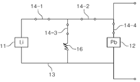
しかし、電位の低いモジュールに突入電流(in rush current)が流れて鉛蓄電池モジュール12またはリチウム電池モジュール11が損傷する可能性がある場合には、接続の前に鉛蓄電池モジュール12とリチウム電池モジュール11との間でバランスを取ることが好ましい。例えば、リチウム電池モジュール11の電位が高い場合には、まず、図4に示すように、第2スイッチ14-2をオフにし、第1スイッチ14-1、第3スイッチ14-3、第4スイッチ14-4をオンにして、リチウム電池モジュール11を可変抵抗16と並列に接続する。このような状態で鉛蓄電池モジュール12とリチウム電池モジュール11との間でバランスが取れるまでしばらく放置する。このとき、可変抵抗16の抵抗値は、リチウム電池モジュール11の状態に応じて適宜選択することができる。また、最初には抵抗値を大きくし、次第に抵抗値を低くすることもできる。そして、図5に示すように、第2スイッチ14-2をオンにして、鉛蓄電池モジュール12とリチウム電池モジュール11とを並列に接続する。そして、しばらくして、図6に示すように、第3スイッチ14-3をオフにする。
However, if there is a possibility of damage to the lead-
逆に、鉛蓄電池モジュール12の電位が高い場合には、まず、図7に示すように、第1スイッチ14-1をオフにし、第2スイッチ14-2、第3スイッチ14-3及び第4スイッチ14-4をオンにして、リチウム電池モジュール12を可変抵抗16に並列に接続する。このような状態でしばらく放置して鉛蓄電池モジュール12とリチウム電池モジュール11との間でバランスが取れれば、図5に示すように、第1スイッチ14-1をオンにして、鉛蓄電池モジュール12とリチウム電池モジュール13とを並列に接続する。そして、しばらくして、図6に示すように第3スイッチ14-3をオフにする。
Conversely, when the potential of the lead-
鉛蓄電池モジュール12とリチウム電池モジュール11との間でバランスが取れるかは、第1検知ユニット21及び第2検知ユニット22で測定された値に応じて決定でき、リチウム電池モジュール11の接続が必要であるかは、モータ1に要求される出力に応じて決定できる。
Whether the lead-
第1検知ユニット21は、リチウム電池モジュール11のリチウム電池セルに接続されて、セルそれぞれの温度及び電圧、リチウム電池モジュール11の出力端に流れる電流などを測定する。第1検知ユニット21は、一つの通信線を用いて直列に接続され、各セルの温度及び電圧などの情報をシリアル通信方式によって制御器30に伝達することができる。
The
第2検知ユニット22は、鉛蓄電池モジュール12の鉛蓄電池セルに接続され、セルそれぞれの温度及び電圧、鉛蓄電池モジュール12の出力端に流れる電流などを測定した後、各セルの温度及び電圧などの情報を制御器30に伝達する。
The
制御器30は、エネルギー貯蔵装置20のリチウム電池モジュール11と鉛蓄電池モジュール12の状態をモニタリングして最適な条件で維持及び使用することができるようにエネルギー貯蔵装置20を管理する。
The
図8に示すように、制御器30は、受信部31、測定部32、比較部33、信号生成部34及び送信部35を含む。制御器30は、第1検知ユニット21と第2検知ユニット22から伝達された情報を介して、リチウム電池モジュール11及び鉛蓄電池モジュール12のセルの温度、電圧、モジュールの出力端の電流などの状態を監視する。さらに、制御器は、セルの状態とモータコントローラ2を介して入力された情報に基づいて生成された制御信号をスイッチングネットワーク15に送信してリチウム電池モジュール11、鉛蓄電池モジュール12及び可変抵抗16の接続状態を変更させることにより、エネルギー貯蔵装置20を総合的に管理する役割を果たす。
As shown in FIG. 8, the
受信部31は、第1検知ユニット21と第2検知ユニット22で測定された温度、電圧、電流などのデータの伝達を受ける。さらに、受信部は、モータコントローラ2を介してモータ1の駆動のために必要な電力データの伝達を受ける。
The
測定部32は、受信部31で受信したデータを用いて、クーロンカウント方式などでリチウム電池モジュール11及び鉛蓄電池モジュール12の充電率(SOC、state of charge)を測定し、健全度(SOH、state of health)を決定する。さらに、測定部は、負荷に出力することが可能な電力を推定し、電流の変化率も計算する。
The measuring
比較部33は、受信部31で受信したデータを用いて、リチウム電池セルの温度を所定の基準温度と比較してリチウム電池セルが安全な状態であるか否かを検査する。また、鉛蓄電池セルの電圧を所定の基準電圧と比較して鉛蓄電池セルが使用できる状態か否かを検査する。また、所定の鉛蓄電池モジュール12の電流値及び電流の変化率と比較して、鉛蓄電池モジュール12にリチウム電池モジュール11を結合しなければならない時点であるか否かも判断する。つまり、鉛蓄電池モジュール12の電流値及び電流の変化率が所定の値以上であって、鉛蓄電池モジュール12の放電率を超える放電が要求されるか否かを判断する。
Using the data received by the receiving
信号生成部34は、リチウム電池モジュール11及び鉛蓄電池モジュール12の充電率とリチウム電池モジュール11の温度及び鉛蓄電池モジュール12の電圧、モータコントローラ2を介して伝達された走行状態、鉛蓄電池モジュール12の電流値及び電流の変化率などを考慮して、リチウム電池モジュール11、鉛蓄電池モジュール12及び可変抵抗16の接続状態を決定する制御信号を発生させてエネルギー貯蔵装置20に伝達する。
The
例えば、リチウム電池モジュール11及び鉛蓄電池モジュール12が十分に充電されており、定速走行中であって特に高出力が要求されない場合には、鉛蓄電池モジュール12のみを使用するようにすることができる。
For example, when the
また、続いてリチウム電池モジュール11を一緒に使用してリチウム電池モジュール11の温度が基準温度以上に上昇すれば、鉛蓄電池モジュール12のみを使用するように変更するための制御信号を発生させてエネルギー貯蔵装置20に伝達する。
In addition, if the temperature of the
制御器30は、モータコントローラ2のモータ制御器に接続されており、停止してから再度出発するか或いは坂道を走行するなどの走行状態を確認することができる。以下では、走行状態に応じた接続状態の変化について説明する。制御器は、走行状態による要求に応じて接続状態を変換するが、リチウム電池モジュール11と鉛蓄電池モジュール12の状態を考慮すると、走行状態に対応して接続状態を変換することが難しい場合には、走行状態による接続状態の変換に優先して、リチウム電池モジュール11と鉛蓄電池モジュール12を保護する方向に接続状態を切り替えることができる。
The
もし、走行状態に応じて大きい出力が必要である場合には、リチウム電池モジュール11が接続された状態に転換するための制御信号を発生させてエネルギー貯蔵装置20に伝達する。鉛蓄電池モジュール12は、十分に充電されている場合にも取り出して使える電力が低いからである。
If a large output is required according to the running state, a control signal is generated and transmitted to the
走行状態は、鉛蓄電池モジュール12の電流値及び電流の変化率によっても判断することができる。つまり、鉛蓄電池モジュール12の電流値及び電流の変化率が所定の値以上であって、鉛蓄電池モジュール12の放電率を超える放電が要求されると判断される場合には、リチウム電池モジュール11が負荷に接続されるように制御信号を発生させる。
The running state can also be determined from the current value and current change rate of the lead-
このとき、リチウム電池モジュール11を鉛蓄電池モジュール12に直接接続することもできるが、直接接続すると、エネルギー貯蔵装置20の出力が急激に変化するため、衝撃が生じることがある。したがって、まず、リチウム電池モジュール11を可変抵抗16に接続した後、リチウム電池モジュール11と鉛蓄電池モジュール12とのバランスが取れた状態でリチウム電池モジュール11を鉛蓄電池モジュール12に接続することが好ましい。しばらくの後、可変抵抗16を分離する。
At this time, the
回生制動による充電が必要な場合には、図9に示すように、第1スイッチ14-1と第2スイッチ14-2をオンにし、第3スイッチ14-3と第4スイッチ14-4をオフにして、リチウム電池モジュール11が回生制動システム7に接続されるようにする。鉛蓄電池モジュール12は、回生制動による充電がほぼ行われないので、回生制動の際にはリチウム電池モジュール11を鉛蓄電池モジュール12と分離して回生制動システム7と接続することが、回生制動による充電効率を向上させることができるという利点がある。
When charging by regenerative braking is required, as shown in FIG. 9, the first switch 14-1 and the second switch 14-2 are turned on, and the third switch 14-3 and the fourth switch 14-4 are turned off. , so that the
また、リチウム電池モジュール11の充電が完了すると、充電されたリチウム電池モジュール11を介して鉛蓄電池モジュール12を充電する方法によって鉛蓄電池モジュール12を充電することができる。上述したように、鉛蓄電池モジュール12は、回生制動による充電がほぼ行われない。この場合には、制御器30が、充電されたリチウム電池モジュール11と鉛蓄電池モジュール12とが互いに接続されるようにスイッチングネットワーク15の接続状態を切り替えることができる制御信号をスイッチングネットワーク15に送信する。
In addition, when the charging of the
以下、上述したハイブリッドエネルギー貯蔵モジュールシステムの作用を図10に基づいて説明する。 The operation of the hybrid energy storage module system described above will now be described with reference to FIG.
車両の走行が開始すると、第1検知ユニット21と第2検知ユニット22は、リチウム電池モジュール11及び鉛蓄電池モジュール12のセルの温度、電圧、モジュールの出力端の電流などを測定する(S1、S2)。
When the vehicle starts running, the
その後、制御器30の測定部32は、第1検知ユニット21と第2検知ユニット22で測定されたデータを用いて、リチウム電池モジュール11及び鉛蓄電池モジュール12の充電率、健全度などを測定する(S3)。充電率の測定結果によって、走行が可能な状態であるか否かを判断する(S4)。測定の結果、走行することが可能な状態であれば、測定された充電率が、電気自動車の運転席に設置されたディスプレイを介して運転者に伝達される。もしリチウム電池モジュール11と鉛蓄電池モジュール12の両方の充電率が低いため充電が必要な場合には、電気自動車の運転席に設置されたディスプレイを介して、運転者に充電が必要であることを知らせる(S12)。
After that, the
その後、制御器30の比較部33は、第1検知ユニット21で測定されたリチウム電池モジュール11の各セルの温度値と基準温度を比較する(S5)。また、第1検知ユニット22で測定された鉛蓄電池モジュール12の各セルの電圧値と基準電圧とを比較する(S6)。比較の結果、リチウム電池モジュール11の各セルの温度値が基準温度以上であり、鉛蓄電池モジュール12の各セルの電圧値が基準電圧以下であって走行が困難である場合には、電気自動車の運転席に設置されたディスプレイを介して運転者に警告をして運転者が対処することができるようにする(S13)。また、必要な場合には、制御器30が電気自動車の運行を停止させる。
Thereafter, the
その後、制御器30は、モータコントローラ2のモータ制御器または鉛蓄電池モジュール12の電流値及び電流の変化率を介して車両の走行状態情報を受信する(S8)。例えば、鉛蓄電池モジュール12の電流値及び電流の変化率が所定の値以上である場合には、車両が停止してからさらに出発するか或いは坂道を走行していると判断することができ、そうでない場合には、車両が定速で走行していることを判断することができる。
After that, the
S4乃至S8のステップはいずれも制御器30で行われ、同時に或いは上述の順序とは異なる順序で行われ得る。
Steps S4 through S8 are all performed by
その後、制御器30の信号生成部34は、S4乃至S8のステップで得られた結果を介して接続状態を決定して制御信号を生成することにより、エネルギー貯蔵装置20に送信する(S9)。
After that, the
その後、エネルギー貯蔵装置20は、制御信号に応じてリチウム電池モジュール11、鉛蓄電池モジュール12及び可変抵抗16を配列した後、放電する(S10)。
After that, the
一定時間が経過する(S11)と、S1乃至S10のステップを繰り返し行う。 After a certain period of time has passed (S11), steps S1 to S10 are repeated.
図11は本発明の他の実施形態によるハイブリッドエネルギー貯蔵モジュールシステムのブロック図である。図11に示すように、ハイブリッドエネルギー貯蔵モジュールシステムは、第1ダイオード17と第2ダイオード18をさらに含んでもよい。
FIG. 11 is a block diagram of a hybrid energy storage module system according to another embodiment of the invention. The hybrid energy storage module system may further include a
第1ダイオード17と第2ダイオード18は、鉛蓄電池モジュール12からリチウム電池モジュール11へ、或いはその逆に突入電流が流れることを防止するための安全装置である。上述したように、鉛蓄電池モジュール12とリチウム電池モジュール11とのバランスを取った状態でリチウム電池モジュール11を接続すると、突入電流が流れる可能性が小さいが、万が一の場合に備えて、第1ダイオード17と第2ダイオード18を設置することができる。第2ダイオード18は、鉛蓄電池モジュール12で負荷ではなく、リチウム電池モジュール11側へ電流が流れることを遮断し、第1ダイオード17は、リチウム電池モジュール11から鉛蓄電池モジュール12へ電流が流れることを遮断し、負荷へのみ電流が流れるようにする。
The
本実施形態の場合には、回生制動のために、第1ダイオード17と第2ダイオード18の方向を変更することができる別のスイッチング装置が必要とされることがある。
For this embodiment, a separate switching device may be required to change the direction of the
以上では、本発明の好適な実施形態について図示及び説明したが、本発明は、上述した特定の実施形態に限定されず、請求の範囲で請求する本発明の要旨を逸脱することなく、当該発明の属する技術分野における通常の知識を有する者によって多様な変形実施が可能なのはもとより、それらの変形実施は本発明の技術的思想や展望から個別的に理解されてはならないだろう。 While the preferred embodiments of the invention have been illustrated and described above, the invention is not limited to the particular embodiments described above and without departing from the scope of the invention as claimed in the claims. Various modifications can be made by those who have ordinary knowledge in the technical field to which the present invention belongs, and these modifications should not be understood individually from the technical idea and perspective of the present invention.
例えば、電流制限回路として可変抵抗16を使用すると説明したが、一般抵抗を使用することもできる。また、複数の抵抗を選択的に直列または並列に接続する方法で抵抗が変化する電流制限回路を構成することもできる。また、抵抗値が異なる複数の抵抗の中からいずれかを選択する方式で電流制限回路を構成することもできる。
For example, although
Claims (10)
第2電池モジュールと、前記第2電池モジュールに比べて放電率が高い第1電池モジュールと、前記第2電池モジュールに対して前記第1電池モジュールを並列に接続または分離するように構成されたスイッチングネットワークとを含み、前記負荷に接続されて電力を供給するように構成されたエネルギー貯蔵装置;
前記第1電池モジュールの状態を示すデータを測定するように構成された第1検知ユニット;
前記第2電池モジュールの状態を示すデータを測定するように構成された第2検知ユニット;及び
前記第1検知ユニットと前記第2検知ユニットからのデータを受信し、前記スイッチングネットワークを制御する制御信号を生成し、前記制御信号を前記スイッチングネットワークに送信する制御器;を含み、
前記制御器は、前記第1電池モジュールが前記第2電池モジュールに接続される前に前記第2電池モジュールが先に負荷に接続されるように前記スイッチングネットワークを制御する制御信号を生成し、
前記制御器は、前記第1検知ユニットと前記第2検知ユニットから受信したデータに基づいて、前記第2電池モジュールに対して前記第1電池モジュールが選択的に接続または分離されるように前記スイッチングネットワークを制御する制御信号を生成し、
前記スイッチングネットワークは、前記第2電池モジュールと前記第1電池モジュールとを互いに並列に接続するネットワークに設置された少なくとも一つのスイッチを含み、
前記制御器は、前記第1電池モジュールが前記第2電池モジュールから分離された後に前記第2電池モジュールが負荷から分離されるように前記スイッチングネットワークを制御する制御信号を生成する、ハイブリッドエネルギー貯蔵モジュールシステム。 An energy storage module system for supplying power required to drive a load, comprising:
a second battery module, a first battery module having a higher discharge rate than the second battery module, and a switching configured to connect or disconnect the first battery module in parallel with the second battery module. an energy storage device configured to be connected to and power the load, comprising: a network;
a first sensing unit configured to measure data indicative of the state of the first battery module;
a second sensing unit configured to measure data indicative of the state of the second battery module; and a control signal for receiving data from the first sensing unit and the second sensing unit and controlling the switching network. and sending said control signal to said switching network;
The controller generates a control signal to control the switching network such that the second battery module is first connected to a load before the first battery module is connected to the second battery module;
The controller controls the switching to selectively connect or disconnect the first battery module with respect to the second battery module based on data received from the first sensing unit and the second sensing unit. generate control signals to control the network,
the switching network includes at least one switch installed in a network connecting the second battery module and the first battery module in parallel ;
The controller generates a control signal to control the switching network such that the second battery module is disconnected from the load after the first battery module is disconnected from the second battery module. system.
第2電池モジュールと、前記第2電池モジュールに比べて放電率が高い第1電池モジュールと、前記第2電池モジュールに対して前記第1電池モジュールを並列に接続または分離するように構成されたスイッチングネットワークとを含み、前記負荷に接続されて電力を供給するように構成されたエネルギー貯蔵装置;
前記第1電池モジュールの状態を示すデータを測定するように構成された第1検知ユニット;
前記第2電池モジュールの状態を示すデータを測定するように構成された第2検知ユニット;及び
前記第1検知ユニットと前記第2検知ユニットからのデータを受信し、前記スイッチングネットワークを制御する制御信号を生成し、前記制御信号を前記スイッチングネットワークに送信する制御器;を含み、
前記制御器は、前記第1電池モジュールが前記第2電池モジュールに接続される前に前記第2電池モジュールが先に負荷に接続されるように前記スイッチングネットワークを制御する制御信号を生成し、
前記制御器は、前記第1検知ユニットと前記第2検知ユニットから受信したデータに基づいて、前記第2電池モジュールに対して前記第1電池モジュールが選択的に接続または分離されるように前記スイッチングネットワークを制御する制御信号を生成し、
前記スイッチングネットワークは、前記第2電池モジュールと前記第1電池モジュールとを互いに並列に接続するネットワークに設置された少なくとも一つのスイッチを含み、
前記エネルギー貯蔵装置は、電流制限回路をさらに含み、
前記スイッチングネットワークは、前記電流制限回路を前記第1電池モジュール又は前記第2電池モジュールに対して選択的に接続または分離するように構成され、
前記制御器は、前記第1検知ユニットと前記第2検知ユニットから受信したデータに基づいて、前記第1電池モジュールに前記第2電池モジュールを接続する前に前記第1電池モジュール又は前記第2電池モジュールと前記電流制限回路を接続するように前記スイッチングネットワークを制御する制御信号を生成することを特徴とする、ハイブリッドエネルギー貯蔵モジュールシステム。 An energy storage module system for supplying power required to drive a load, comprising:
a second battery module, a first battery module having a higher discharge rate than the second battery module, and a switching configured to connect or disconnect the first battery module in parallel with the second battery module. an energy storage device configured to be connected to and power the load, comprising: a network;
a first sensing unit configured to measure data indicative of the state of the first battery module;
a second sensing unit configured to measure data indicative of the state of the second battery module; and
a controller that receives data from the first sensing unit and the second sensing unit, generates a control signal for controlling the switching network, and sends the control signal to the switching network;
The controller generates a control signal to control the switching network such that the second battery module is first connected to a load before the first battery module is connected to the second battery module;
The controller controls the switching to selectively connect or disconnect the first battery module with respect to the second battery module based on data received from the first sensing unit and the second sensing unit. generate control signals to control the network,
the switching network includes at least one switch installed in a network connecting the second battery module and the first battery module in parallel;
the energy storage device further comprising a current limiting circuit;
the switching network is configured to selectively connect or disconnect the current limiting circuit to the first battery module or the second battery module;
The controller detects the first battery module or the second battery module before connecting the second battery module to the first battery module based on the data received from the first sensing unit and the second sensing unit. A hybrid energy storage module system, characterized in that it generates a control signal that controls said switching network to connect a module and said current limiting circuit.
第2電池モジュールと、前記第2電池モジュールに比べて放電率が高い第1電池モジュールと、前記第2電池モジュールに対して前記第1電池モジュールを並列に接続または分離するように構成されたスイッチングネットワークとを含み、前記負荷に接続されて電力を供給するように構成されたエネルギー貯蔵装置;
前記第1電池モジュールの状態を示すデータを測定するように構成された第1検知ユニット;
前記第2電池モジュールの状態を示すデータを測定するように構成された第2検知ユニット;及び
前記第1検知ユニットと前記第2検知ユニットからのデータを受信し、前記スイッチングネットワークを制御する制御信号を生成し、前記制御信号を前記スイッチングネットワークに送信する制御器;を含み、
前記制御器は、前記第1電池モジュールが前記第2電池モジュールに接続される前に前記第2電池モジュールが先に負荷に接続されるように前記スイッチングネットワークを制御する制御信号を生成し、
前記制御器は、前記第1検知ユニットと前記第2検知ユニットから受信したデータに基づいて、前記第2電池モジュールに対して前記第1電池モジュールが選択的に接続または分離されるように前記スイッチングネットワークを制御する制御信号を生成し、
前記スイッチングネットワークは、前記第2電池モジュールと前記第1電池モジュールとを互いに並列に接続するネットワークに設置された少なくとも一つのスイッチを含み、
前記制御器は、前記第2検知ユニットから受信した前記第2電池モジュールの出力端に流れる電流値の大きさと電流値の傾きが所定の値以上であれば、前記第2電池モジュールに前記第1電池モジュールが接続されるように前記スイッチングネットワークを制御する制御信号を生成する、ハイブリッドエネルギー貯蔵モジュールシステム。 An energy storage module system for supplying power required to drive a load, comprising:
a second battery module, a first battery module having a higher discharge rate than the second battery module, and a switching configured to connect or disconnect the first battery module in parallel with the second battery module. an energy storage device configured to be connected to and power the load, comprising: a network;
a first sensing unit configured to measure data indicative of the state of the first battery module;
a second sensing unit configured to measure data indicative of the state of the second battery module; and
a controller that receives data from the first sensing unit and the second sensing unit, generates a control signal for controlling the switching network, and sends the control signal to the switching network;
The controller generates a control signal to control the switching network such that the second battery module is first connected to a load before the first battery module is connected to the second battery module;
The controller controls the switching to selectively connect or disconnect the first battery module with respect to the second battery module based on data received from the first sensing unit and the second sensing unit. generate control signals to control the network,
the switching network includes at least one switch installed in a network connecting the second battery module and the first battery module in parallel;
If the magnitude of the current flowing through the output end of the second battery module and the slope of the current received from the second detection unit are greater than or equal to a predetermined value, the controller outputs the first voltage to the second battery module. A hybrid energy storage module system that generates control signals to control the switching network such that battery modules are connected.
第2電池モジュールと、前記第2電池モジュールに比べて放電率が高い第1電池モジュールと、前記第2電池モジュールに対して前記第1電池モジュールを並列に接続または分離するように構成されたスイッチングネットワークとを含み、前記負荷に接続されて電力を供給するように構成されたエネルギー貯蔵装置;
前記第1電池モジュールの状態を示すデータを測定するように構成された第1検知ユニット;
前記第2電池モジュールの状態を示すデータを測定するように構成された第2検知ユニット;及び
前記第1検知ユニットと前記第2検知ユニットからのデータを受信し、前記スイッチングネットワークを制御する制御信号を生成し、前記制御信号を前記スイッチングネットワークに送信する制御器;を含み、
前記制御器は、前記第1電池モジュールが前記第2電池モジュールに接続される前に前記第2電池モジュールが先に負荷に接続されるように前記スイッチングネットワークを制御する制御信号を生成し、
前記制御器は、前記第1検知ユニットと前記第2検知ユニットから受信したデータに基づいて、前記第2電池モジュールに対して前記第1電池モジュールが選択的に接続または分離されるように前記スイッチングネットワークを制御する制御信号を生成し、
前記スイッチングネットワークは、前記第2電池モジュールと前記第1電池モジュールとを互いに並列に接続するネットワークに設置された少なくとも一つのスイッチを含み、
前記スイッチングネットワークには、前記第1電池モジュールから前記第2電池モジュールに電流が流れることを防止する第1ダイオード、及び前記第2電池モジュールから前記第1電池モジュールに電流が流れることを防止する第2ダイオードが設置された、ハイブリッドエネルギー貯蔵モジュールシステム。 An energy storage module system for supplying power required to drive a load, comprising:
a second battery module, a first battery module having a higher discharge rate than the second battery module, and a switching configured to connect or disconnect the first battery module in parallel with the second battery module. an energy storage device configured to be connected to and power the load, comprising: a network;
a first sensing unit configured to measure data indicative of the state of the first battery module;
a second sensing unit configured to measure data indicative of the state of the second battery module; and
a controller that receives data from the first sensing unit and the second sensing unit, generates a control signal for controlling the switching network, and sends the control signal to the switching network;
The controller generates a control signal to control the switching network such that the second battery module is first connected to a load before the first battery module is connected to the second battery module;
The controller controls the switching to selectively connect or disconnect the first battery module with respect to the second battery module based on data received from the first sensing unit and the second sensing unit. generate control signals to control the network,
the switching network includes at least one switch installed in a network connecting the second battery module and the first battery module in parallel;
The switching network includes a first diode that prevents current from flowing from the first battery module to the second battery module, and a second diode that prevents current from flowing from the second battery module to the first battery module. A hybrid energy storage module system with two diodes installed.
Applications Claiming Priority (3)
| Application Number | Priority Date | Filing Date | Title |
|---|---|---|---|
| KR1020180073832A KR101930214B1 (en) | 2018-06-27 | 2018-06-27 | Hybrid energy storage module system with supplementary battery |
| KR10-2018-0073832 | 2018-06-27 | ||
| PCT/KR2019/001978 WO2020004768A1 (en) | 2018-06-27 | 2019-02-19 | Hybrid energy storage module system having auxiliary battery |
Publications (2)
| Publication Number | Publication Date |
|---|---|
| JP2021529497A JP2021529497A (en) | 2021-10-28 |
| JP7140852B2 true JP7140852B2 (en) | 2022-09-21 |
Family
ID=65007424
Family Applications (1)
| Application Number | Title | Priority Date | Filing Date |
|---|---|---|---|
| JP2020568454A Active JP7140852B2 (en) | 2018-06-27 | 2019-02-19 | Hybrid energy storage module system with auxiliary battery |
Country Status (6)
| Country | Link |
|---|---|
| US (1) | US11830999B2 (en) |
| EP (1) | EP3817180A4 (en) |
| JP (1) | JP7140852B2 (en) |
| KR (1) | KR101930214B1 (en) |
| CN (1) | CN112335149A (en) |
| WO (1) | WO2020004768A1 (en) |
Families Citing this family (6)
| Publication number | Priority date | Publication date | Assignee | Title |
|---|---|---|---|---|
| KR102111412B1 (en) * | 2018-12-26 | 2020-05-15 | 한국기술교육대학교 산학협력단 | Hybrid battery management system |
| CN113574714A (en) * | 2019-05-16 | 2021-10-29 | Oppo广东移动通信有限公司 | Power supply circuit, charging and discharging circuit and intelligent terminal |
| WO2021079467A1 (en) * | 2019-10-24 | 2021-04-29 | 日本碍子株式会社 | User interface providing device, method of providing discharge capacity of secondary battery system, and method of providing charge/discharge capacity of secondary battery system |
| JP2022029393A (en) * | 2020-08-04 | 2022-02-17 | 旭 成定 | Storage battery type electric vehicle |
| CN113964914B (en) * | 2021-11-08 | 2023-07-21 | 深圳市迪浦电子有限公司 | Mobile phone battery power management system and method |
| CN114537165B (en) * | 2022-02-17 | 2023-07-18 | 岚图汽车科技有限公司 | Lithium battery system, lithium battery control method, readable storage medium, and control device |
Citations (6)
| Publication number | Priority date | Publication date | Assignee | Title |
|---|---|---|---|---|
| JP2011178384A (en) | 2010-02-03 | 2011-09-15 | Denso Corp | On-vehicle power source device |
| JP2013201891A (en) | 2012-03-23 | 2013-10-03 | Samsung Sdi Co Ltd | Battery pack and control method therefor |
| JP2014200123A (en) | 2013-03-29 | 2014-10-23 | 三洋電機株式会社 | On-vehicle power supply unit and vehicle having the same |
| US20150202984A1 (en) | 2014-01-23 | 2015-07-23 | Johnson Controls Technology Company | Switched passive architectures for batteries having two different chemistries |
| JP2016067142A (en) | 2014-09-25 | 2016-04-28 | 日立化成株式会社 | Power supply system and automobile |
| JP2016174475A (en) | 2015-03-17 | 2016-09-29 | 日立化成株式会社 | Power storage system |
Family Cites Families (11)
| Publication number | Priority date | Publication date | Assignee | Title |
|---|---|---|---|---|
| KR100559334B1 (en) | 2003-12-30 | 2006-03-15 | 현대자동차주식회사 | Apparatus for cooling battery and method of the same |
| KR20050070727A (en) | 2003-12-30 | 2005-07-07 | 현대자동차주식회사 | Apparatus for cooling battery |
| KR20100001877A (en) | 2008-06-27 | 2010-01-06 | 웅진코웨이주식회사 | Bidet having cover for micro control device |
| JP2010093993A (en) | 2008-10-10 | 2010-04-22 | Toyota Motor Corp | Power supply control device and vehicle with the same |
| KR20110081622A (en) | 2010-01-08 | 2011-07-14 | (주)브이이엔에스 | Electric vehicle and method for cooling battery thereof |
| TW201214919A (en) | 2010-09-24 | 2012-04-01 | Lite On Clean Energy Technology Corp | Hybrid battery module and battery management method |
| KR101281066B1 (en) | 2011-10-18 | 2013-07-09 | 송영길 | Hybrid Battery System for Electric Vehicle |
| WO2013115034A1 (en) | 2012-01-31 | 2013-08-08 | 三洋電機株式会社 | Power source device for vehicle and vehicle provided with said power source device |
| RU2635360C2 (en) * | 2013-07-30 | 2017-11-13 | ЭлДжи КЕМ, ЛТД. | Device and method for battery management |
| KR101553063B1 (en) | 2015-01-20 | 2015-09-15 | 주식회사 제이에스영테크 | Hybrid energy storage module system |
| JP6658314B2 (en) | 2016-06-02 | 2020-03-04 | 日立化成株式会社 | Vehicle power supply system and automobile |
-
2018
- 2018-06-27 KR KR1020180073832A patent/KR101930214B1/en active IP Right Grant
-
2019
- 2019-02-19 US US17/251,616 patent/US11830999B2/en active Active
- 2019-02-19 EP EP19827476.3A patent/EP3817180A4/en active Pending
- 2019-02-19 WO PCT/KR2019/001978 patent/WO2020004768A1/en unknown
- 2019-02-19 JP JP2020568454A patent/JP7140852B2/en active Active
- 2019-02-19 CN CN201980043014.2A patent/CN112335149A/en active Pending
Patent Citations (6)
| Publication number | Priority date | Publication date | Assignee | Title |
|---|---|---|---|---|
| JP2011178384A (en) | 2010-02-03 | 2011-09-15 | Denso Corp | On-vehicle power source device |
| JP2013201891A (en) | 2012-03-23 | 2013-10-03 | Samsung Sdi Co Ltd | Battery pack and control method therefor |
| JP2014200123A (en) | 2013-03-29 | 2014-10-23 | 三洋電機株式会社 | On-vehicle power supply unit and vehicle having the same |
| US20150202984A1 (en) | 2014-01-23 | 2015-07-23 | Johnson Controls Technology Company | Switched passive architectures for batteries having two different chemistries |
| JP2016067142A (en) | 2014-09-25 | 2016-04-28 | 日立化成株式会社 | Power supply system and automobile |
| JP2016174475A (en) | 2015-03-17 | 2016-09-29 | 日立化成株式会社 | Power storage system |
Also Published As
| Publication number | Publication date |
|---|---|
| EP3817180A4 (en) | 2022-03-09 |
| US20210111452A1 (en) | 2021-04-15 |
| KR101930214B1 (en) | 2018-12-17 |
| US11830999B2 (en) | 2023-11-28 |
| EP3817180A1 (en) | 2021-05-05 |
| WO2020004768A1 (en) | 2020-01-02 |
| JP2021529497A (en) | 2021-10-28 |
| CN112335149A (en) | 2021-02-05 |
Similar Documents
| Publication | Publication Date | Title |
|---|---|---|
| JP6419992B2 (en) | Hybrid energy storage module system | |
| JP7140852B2 (en) | Hybrid energy storage module system with auxiliary battery | |
| CN108081978B (en) | Battery pre-heating prior to fast charging | |
| KR101281066B1 (en) | Hybrid Battery System for Electric Vehicle | |
| US10259336B2 (en) | Charging a battery using interpack switch | |
| US8330418B2 (en) | Power supply device capable of equalizing electrical properties of batteries | |
| US9358899B2 (en) | Method for revitalizing and increasing lithium ion battery capacity | |
| CN104160580A (en) | Battery pack and electric vehicle | |
| US10809305B2 (en) | System and method for detecting and responding to a battery over-discharge condition within a vehicle | |
| JP2012105527A (en) | Apparatus and method for charging electric vehicle | |
| CN104085312A (en) | Battery management system of electric car | |
| CN102893168A (en) | Power supply device | |
| CN106004858B (en) | Torque assist based on battery state of charge allocation | |
| CN214189325U (en) | Automotive charger baby system | |
| JP6459277B2 (en) | Series-parallel battery pack and series-parallel battery pack control method | |
| KR20210028991A (en) | Method for controlling sub battery of electric vehicle | |
| WO2023158427A1 (en) | Electrical storage for battery electric vehicle |
Legal Events
| Date | Code | Title | Description |
|---|---|---|---|
| A621 | Written request for application examination |
Free format text: JAPANESE INTERMEDIATE CODE: A621 Effective date: 20210115 |
|
| A977 | Report on retrieval |
Free format text: JAPANESE INTERMEDIATE CODE: A971007 Effective date: 20220224 |
|
| A131 | Notification of reasons for refusal |
Free format text: JAPANESE INTERMEDIATE CODE: A131 Effective date: 20220308 |
|
| A521 | Request for written amendment filed |
Free format text: JAPANESE INTERMEDIATE CODE: A523 Effective date: 20220401 |
|
| TRDD | Decision of grant or rejection written | ||
| A01 | Written decision to grant a patent or to grant a registration (utility model) |
Free format text: JAPANESE INTERMEDIATE CODE: A01 Effective date: 20220816 |
|
| A61 | First payment of annual fees (during grant procedure) |
Free format text: JAPANESE INTERMEDIATE CODE: A61 Effective date: 20220908 |
|
| R150 | Certificate of patent or registration of utility model |
Ref document number: 7140852 Country of ref document: JP Free format text: JAPANESE INTERMEDIATE CODE: R150 |