CN1237681C - Electric device and apparatus for charging battery unit, and method for charging and discharging - Google Patents
Electric device and apparatus for charging battery unit, and method for charging and discharging Download PDFInfo
- Publication number
- CN1237681C CN1237681C CNB008111634A CN00811163A CN1237681C CN 1237681 C CN1237681 C CN 1237681C CN B008111634 A CNB008111634 A CN B008111634A CN 00811163 A CN00811163 A CN 00811163A CN 1237681 C CN1237681 C CN 1237681C
- Authority
- CN
- China
- Prior art keywords
- mentioned
- charging
- battery unit
- battery
- batteries
- Prior art date
- Legal status (The legal status is an assumption and is not a legal conclusion. Google has not performed a legal analysis and makes no representation as to the accuracy of the status listed.)
- Expired - Fee Related
Links
Images


Classifications
-
- H—ELECTRICITY
- H02—GENERATION; CONVERSION OR DISTRIBUTION OF ELECTRIC POWER
- H02J—CIRCUIT ARRANGEMENTS OR SYSTEMS FOR SUPPLYING OR DISTRIBUTING ELECTRIC POWER; SYSTEMS FOR STORING ELECTRIC ENERGY
- H02J7/00—Circuit arrangements for charging or depolarising batteries or for supplying loads from batteries
-
- H—ELECTRICITY
- H02—GENERATION; CONVERSION OR DISTRIBUTION OF ELECTRIC POWER
- H02J—CIRCUIT ARRANGEMENTS OR SYSTEMS FOR SUPPLYING OR DISTRIBUTING ELECTRIC POWER; SYSTEMS FOR STORING ELECTRIC ENERGY
- H02J9/00—Circuit arrangements for emergency or stand-by power supply, e.g. for emergency lighting
- H02J9/04—Circuit arrangements for emergency or stand-by power supply, e.g. for emergency lighting in which the distribution system is disconnected from the normal source and connected to a standby source
- H02J9/06—Circuit arrangements for emergency or stand-by power supply, e.g. for emergency lighting in which the distribution system is disconnected from the normal source and connected to a standby source with automatic change-over, e.g. UPS systems
-
- B—PERFORMING OPERATIONS; TRANSPORTING
- B60—VEHICLES IN GENERAL
- B60L—PROPULSION OF ELECTRICALLY-PROPELLED VEHICLES; SUPPLYING ELECTRIC POWER FOR AUXILIARY EQUIPMENT OF ELECTRICALLY-PROPELLED VEHICLES; ELECTRODYNAMIC BRAKE SYSTEMS FOR VEHICLES IN GENERAL; MAGNETIC SUSPENSION OR LEVITATION FOR VEHICLES; MONITORING OPERATING VARIABLES OF ELECTRICALLY-PROPELLED VEHICLES; ELECTRIC SAFETY DEVICES FOR ELECTRICALLY-PROPELLED VEHICLES
- B60L3/00—Electric devices on electrically-propelled vehicles for safety purposes; Monitoring operating variables, e.g. speed, deceleration or energy consumption
- B60L3/0023—Detecting, eliminating, remedying or compensating for drive train abnormalities, e.g. failures within the drive train
- B60L3/0046—Detecting, eliminating, remedying or compensating for drive train abnormalities, e.g. failures within the drive train relating to electric energy storage systems, e.g. batteries or capacitors
-
- B—PERFORMING OPERATIONS; TRANSPORTING
- B60—VEHICLES IN GENERAL
- B60L—PROPULSION OF ELECTRICALLY-PROPELLED VEHICLES; SUPPLYING ELECTRIC POWER FOR AUXILIARY EQUIPMENT OF ELECTRICALLY-PROPELLED VEHICLES; ELECTRODYNAMIC BRAKE SYSTEMS FOR VEHICLES IN GENERAL; MAGNETIC SUSPENSION OR LEVITATION FOR VEHICLES; MONITORING OPERATING VARIABLES OF ELECTRICALLY-PROPELLED VEHICLES; ELECTRIC SAFETY DEVICES FOR ELECTRICALLY-PROPELLED VEHICLES
- B60L3/00—Electric devices on electrically-propelled vehicles for safety purposes; Monitoring operating variables, e.g. speed, deceleration or energy consumption
- B60L3/12—Recording operating variables ; Monitoring of operating variables
-
- B—PERFORMING OPERATIONS; TRANSPORTING
- B60—VEHICLES IN GENERAL
- B60L—PROPULSION OF ELECTRICALLY-PROPELLED VEHICLES; SUPPLYING ELECTRIC POWER FOR AUXILIARY EQUIPMENT OF ELECTRICALLY-PROPELLED VEHICLES; ELECTRODYNAMIC BRAKE SYSTEMS FOR VEHICLES IN GENERAL; MAGNETIC SUSPENSION OR LEVITATION FOR VEHICLES; MONITORING OPERATING VARIABLES OF ELECTRICALLY-PROPELLED VEHICLES; ELECTRIC SAFETY DEVICES FOR ELECTRICALLY-PROPELLED VEHICLES
- B60L50/00—Electric propulsion with power supplied within the vehicle
- B60L50/50—Electric propulsion with power supplied within the vehicle using propulsion power supplied by batteries or fuel cells
- B60L50/51—Electric propulsion with power supplied within the vehicle using propulsion power supplied by batteries or fuel cells characterised by AC-motors
-
- B—PERFORMING OPERATIONS; TRANSPORTING
- B60—VEHICLES IN GENERAL
- B60L—PROPULSION OF ELECTRICALLY-PROPELLED VEHICLES; SUPPLYING ELECTRIC POWER FOR AUXILIARY EQUIPMENT OF ELECTRICALLY-PROPELLED VEHICLES; ELECTRODYNAMIC BRAKE SYSTEMS FOR VEHICLES IN GENERAL; MAGNETIC SUSPENSION OR LEVITATION FOR VEHICLES; MONITORING OPERATING VARIABLES OF ELECTRICALLY-PROPELLED VEHICLES; ELECTRIC SAFETY DEVICES FOR ELECTRICALLY-PROPELLED VEHICLES
- B60L53/00—Methods of charging batteries, specially adapted for electric vehicles; Charging stations or on-board charging equipment therefor; Exchange of energy storage elements in electric vehicles
- B60L53/10—Methods of charging batteries, specially adapted for electric vehicles; Charging stations or on-board charging equipment therefor; Exchange of energy storage elements in electric vehicles characterised by the energy transfer between the charging station and the vehicle
- B60L53/14—Conductive energy transfer
-
- B—PERFORMING OPERATIONS; TRANSPORTING
- B60—VEHICLES IN GENERAL
- B60L—PROPULSION OF ELECTRICALLY-PROPELLED VEHICLES; SUPPLYING ELECTRIC POWER FOR AUXILIARY EQUIPMENT OF ELECTRICALLY-PROPELLED VEHICLES; ELECTRODYNAMIC BRAKE SYSTEMS FOR VEHICLES IN GENERAL; MAGNETIC SUSPENSION OR LEVITATION FOR VEHICLES; MONITORING OPERATING VARIABLES OF ELECTRICALLY-PROPELLED VEHICLES; ELECTRIC SAFETY DEVICES FOR ELECTRICALLY-PROPELLED VEHICLES
- B60L53/00—Methods of charging batteries, specially adapted for electric vehicles; Charging stations or on-board charging equipment therefor; Exchange of energy storage elements in electric vehicles
- B60L53/60—Monitoring or controlling charging stations
- B60L53/65—Monitoring or controlling charging stations involving identification of vehicles or their battery types
-
- B—PERFORMING OPERATIONS; TRANSPORTING
- B60—VEHICLES IN GENERAL
- B60L—PROPULSION OF ELECTRICALLY-PROPELLED VEHICLES; SUPPLYING ELECTRIC POWER FOR AUXILIARY EQUIPMENT OF ELECTRICALLY-PROPELLED VEHICLES; ELECTRODYNAMIC BRAKE SYSTEMS FOR VEHICLES IN GENERAL; MAGNETIC SUSPENSION OR LEVITATION FOR VEHICLES; MONITORING OPERATING VARIABLES OF ELECTRICALLY-PROPELLED VEHICLES; ELECTRIC SAFETY DEVICES FOR ELECTRICALLY-PROPELLED VEHICLES
- B60L58/00—Methods or circuit arrangements for monitoring or controlling batteries or fuel cells, specially adapted for electric vehicles
- B60L58/10—Methods or circuit arrangements for monitoring or controlling batteries or fuel cells, specially adapted for electric vehicles for monitoring or controlling batteries
- B60L58/12—Methods or circuit arrangements for monitoring or controlling batteries or fuel cells, specially adapted for electric vehicles for monitoring or controlling batteries responding to state of charge [SoC]
- B60L58/15—Preventing overcharging
-
- B—PERFORMING OPERATIONS; TRANSPORTING
- B60—VEHICLES IN GENERAL
- B60L—PROPULSION OF ELECTRICALLY-PROPELLED VEHICLES; SUPPLYING ELECTRIC POWER FOR AUXILIARY EQUIPMENT OF ELECTRICALLY-PROPELLED VEHICLES; ELECTRODYNAMIC BRAKE SYSTEMS FOR VEHICLES IN GENERAL; MAGNETIC SUSPENSION OR LEVITATION FOR VEHICLES; MONITORING OPERATING VARIABLES OF ELECTRICALLY-PROPELLED VEHICLES; ELECTRIC SAFETY DEVICES FOR ELECTRICALLY-PROPELLED VEHICLES
- B60L58/00—Methods or circuit arrangements for monitoring or controlling batteries or fuel cells, specially adapted for electric vehicles
- B60L58/10—Methods or circuit arrangements for monitoring or controlling batteries or fuel cells, specially adapted for electric vehicles for monitoring or controlling batteries
- B60L58/18—Methods or circuit arrangements for monitoring or controlling batteries or fuel cells, specially adapted for electric vehicles for monitoring or controlling batteries of two or more battery modules
- B60L58/21—Methods or circuit arrangements for monitoring or controlling batteries or fuel cells, specially adapted for electric vehicles for monitoring or controlling batteries of two or more battery modules having the same nominal voltage
-
- H—ELECTRICITY
- H02—GENERATION; CONVERSION OR DISTRIBUTION OF ELECTRIC POWER
- H02J—CIRCUIT ARRANGEMENTS OR SYSTEMS FOR SUPPLYING OR DISTRIBUTING ELECTRIC POWER; SYSTEMS FOR STORING ELECTRIC ENERGY
- H02J7/00—Circuit arrangements for charging or depolarising batteries or for supplying loads from batteries
- H02J7/0013—Circuit arrangements for charging or depolarising batteries or for supplying loads from batteries acting upon several batteries simultaneously or sequentially
- H02J7/0024—Parallel/serial switching of connection of batteries to charge or load circuit
-
- B—PERFORMING OPERATIONS; TRANSPORTING
- B60—VEHICLES IN GENERAL
- B60L—PROPULSION OF ELECTRICALLY-PROPELLED VEHICLES; SUPPLYING ELECTRIC POWER FOR AUXILIARY EQUIPMENT OF ELECTRICALLY-PROPELLED VEHICLES; ELECTRODYNAMIC BRAKE SYSTEMS FOR VEHICLES IN GENERAL; MAGNETIC SUSPENSION OR LEVITATION FOR VEHICLES; MONITORING OPERATING VARIABLES OF ELECTRICALLY-PROPELLED VEHICLES; ELECTRIC SAFETY DEVICES FOR ELECTRICALLY-PROPELLED VEHICLES
- B60L2210/00—Converter types
- B60L2210/30—AC to DC converters
-
- B—PERFORMING OPERATIONS; TRANSPORTING
- B60—VEHICLES IN GENERAL
- B60L—PROPULSION OF ELECTRICALLY-PROPELLED VEHICLES; SUPPLYING ELECTRIC POWER FOR AUXILIARY EQUIPMENT OF ELECTRICALLY-PROPELLED VEHICLES; ELECTRODYNAMIC BRAKE SYSTEMS FOR VEHICLES IN GENERAL; MAGNETIC SUSPENSION OR LEVITATION FOR VEHICLES; MONITORING OPERATING VARIABLES OF ELECTRICALLY-PROPELLED VEHICLES; ELECTRIC SAFETY DEVICES FOR ELECTRICALLY-PROPELLED VEHICLES
- B60L2240/00—Control parameters of input or output; Target parameters
- B60L2240/10—Vehicle control parameters
- B60L2240/12—Speed
-
- B—PERFORMING OPERATIONS; TRANSPORTING
- B60—VEHICLES IN GENERAL
- B60L—PROPULSION OF ELECTRICALLY-PROPELLED VEHICLES; SUPPLYING ELECTRIC POWER FOR AUXILIARY EQUIPMENT OF ELECTRICALLY-PROPELLED VEHICLES; ELECTRODYNAMIC BRAKE SYSTEMS FOR VEHICLES IN GENERAL; MAGNETIC SUSPENSION OR LEVITATION FOR VEHICLES; MONITORING OPERATING VARIABLES OF ELECTRICALLY-PROPELLED VEHICLES; ELECTRIC SAFETY DEVICES FOR ELECTRICALLY-PROPELLED VEHICLES
- B60L2240/00—Control parameters of input or output; Target parameters
- B60L2240/40—Drive Train control parameters
- B60L2240/54—Drive Train control parameters related to batteries
- B60L2240/545—Temperature
-
- B—PERFORMING OPERATIONS; TRANSPORTING
- B60—VEHICLES IN GENERAL
- B60L—PROPULSION OF ELECTRICALLY-PROPELLED VEHICLES; SUPPLYING ELECTRIC POWER FOR AUXILIARY EQUIPMENT OF ELECTRICALLY-PROPELLED VEHICLES; ELECTRODYNAMIC BRAKE SYSTEMS FOR VEHICLES IN GENERAL; MAGNETIC SUSPENSION OR LEVITATION FOR VEHICLES; MONITORING OPERATING VARIABLES OF ELECTRICALLY-PROPELLED VEHICLES; ELECTRIC SAFETY DEVICES FOR ELECTRICALLY-PROPELLED VEHICLES
- B60L2240/00—Control parameters of input or output; Target parameters
- B60L2240/40—Drive Train control parameters
- B60L2240/54—Drive Train control parameters related to batteries
- B60L2240/547—Voltage
-
- B—PERFORMING OPERATIONS; TRANSPORTING
- B60—VEHICLES IN GENERAL
- B60L—PROPULSION OF ELECTRICALLY-PROPELLED VEHICLES; SUPPLYING ELECTRIC POWER FOR AUXILIARY EQUIPMENT OF ELECTRICALLY-PROPELLED VEHICLES; ELECTRODYNAMIC BRAKE SYSTEMS FOR VEHICLES IN GENERAL; MAGNETIC SUSPENSION OR LEVITATION FOR VEHICLES; MONITORING OPERATING VARIABLES OF ELECTRICALLY-PROPELLED VEHICLES; ELECTRIC SAFETY DEVICES FOR ELECTRICALLY-PROPELLED VEHICLES
- B60L2240/00—Control parameters of input or output; Target parameters
- B60L2240/40—Drive Train control parameters
- B60L2240/54—Drive Train control parameters related to batteries
- B60L2240/549—Current
-
- B—PERFORMING OPERATIONS; TRANSPORTING
- B60—VEHICLES IN GENERAL
- B60L—PROPULSION OF ELECTRICALLY-PROPELLED VEHICLES; SUPPLYING ELECTRIC POWER FOR AUXILIARY EQUIPMENT OF ELECTRICALLY-PROPELLED VEHICLES; ELECTRODYNAMIC BRAKE SYSTEMS FOR VEHICLES IN GENERAL; MAGNETIC SUSPENSION OR LEVITATION FOR VEHICLES; MONITORING OPERATING VARIABLES OF ELECTRICALLY-PROPELLED VEHICLES; ELECTRIC SAFETY DEVICES FOR ELECTRICALLY-PROPELLED VEHICLES
- B60L2240/00—Control parameters of input or output; Target parameters
- B60L2240/80—Time limits
-
- B—PERFORMING OPERATIONS; TRANSPORTING
- B60—VEHICLES IN GENERAL
- B60L—PROPULSION OF ELECTRICALLY-PROPELLED VEHICLES; SUPPLYING ELECTRIC POWER FOR AUXILIARY EQUIPMENT OF ELECTRICALLY-PROPELLED VEHICLES; ELECTRODYNAMIC BRAKE SYSTEMS FOR VEHICLES IN GENERAL; MAGNETIC SUSPENSION OR LEVITATION FOR VEHICLES; MONITORING OPERATING VARIABLES OF ELECTRICALLY-PROPELLED VEHICLES; ELECTRIC SAFETY DEVICES FOR ELECTRICALLY-PROPELLED VEHICLES
- B60L2250/00—Driver interactions
- B60L2250/10—Driver interactions by alarm
-
- B—PERFORMING OPERATIONS; TRANSPORTING
- B60—VEHICLES IN GENERAL
- B60L—PROPULSION OF ELECTRICALLY-PROPELLED VEHICLES; SUPPLYING ELECTRIC POWER FOR AUXILIARY EQUIPMENT OF ELECTRICALLY-PROPELLED VEHICLES; ELECTRODYNAMIC BRAKE SYSTEMS FOR VEHICLES IN GENERAL; MAGNETIC SUSPENSION OR LEVITATION FOR VEHICLES; MONITORING OPERATING VARIABLES OF ELECTRICALLY-PROPELLED VEHICLES; ELECTRIC SAFETY DEVICES FOR ELECTRICALLY-PROPELLED VEHICLES
- B60L2250/00—Driver interactions
- B60L2250/16—Driver interactions by display
-
- H—ELECTRICITY
- H01—ELECTRIC ELEMENTS
- H01M—PROCESSES OR MEANS, e.g. BATTERIES, FOR THE DIRECT CONVERSION OF CHEMICAL ENERGY INTO ELECTRICAL ENERGY
- H01M10/00—Secondary cells; Manufacture thereof
- H01M10/42—Methods or arrangements for servicing or maintenance of secondary cells or secondary half-cells
- H01M10/425—Structural combination with electronic components, e.g. electronic circuits integrated to the outside of the casing
- H01M10/4257—Smart batteries, e.g. electronic circuits inside the housing of the cells or batteries
-
- Y—GENERAL TAGGING OF NEW TECHNOLOGICAL DEVELOPMENTS; GENERAL TAGGING OF CROSS-SECTIONAL TECHNOLOGIES SPANNING OVER SEVERAL SECTIONS OF THE IPC; TECHNICAL SUBJECTS COVERED BY FORMER USPC CROSS-REFERENCE ART COLLECTIONS [XRACs] AND DIGESTS
- Y02—TECHNOLOGIES OR APPLICATIONS FOR MITIGATION OR ADAPTATION AGAINST CLIMATE CHANGE
- Y02E—REDUCTION OF GREENHOUSE GAS [GHG] EMISSIONS, RELATED TO ENERGY GENERATION, TRANSMISSION OR DISTRIBUTION
- Y02E60/00—Enabling technologies; Technologies with a potential or indirect contribution to GHG emissions mitigation
- Y02E60/10—Energy storage using batteries
-
- Y—GENERAL TAGGING OF NEW TECHNOLOGICAL DEVELOPMENTS; GENERAL TAGGING OF CROSS-SECTIONAL TECHNOLOGIES SPANNING OVER SEVERAL SECTIONS OF THE IPC; TECHNICAL SUBJECTS COVERED BY FORMER USPC CROSS-REFERENCE ART COLLECTIONS [XRACs] AND DIGESTS
- Y02—TECHNOLOGIES OR APPLICATIONS FOR MITIGATION OR ADAPTATION AGAINST CLIMATE CHANGE
- Y02T—CLIMATE CHANGE MITIGATION TECHNOLOGIES RELATED TO TRANSPORTATION
- Y02T10/00—Road transport of goods or passengers
- Y02T10/60—Other road transportation technologies with climate change mitigation effect
- Y02T10/70—Energy storage systems for electromobility, e.g. batteries
-
- Y—GENERAL TAGGING OF NEW TECHNOLOGICAL DEVELOPMENTS; GENERAL TAGGING OF CROSS-SECTIONAL TECHNOLOGIES SPANNING OVER SEVERAL SECTIONS OF THE IPC; TECHNICAL SUBJECTS COVERED BY FORMER USPC CROSS-REFERENCE ART COLLECTIONS [XRACs] AND DIGESTS
- Y02—TECHNOLOGIES OR APPLICATIONS FOR MITIGATION OR ADAPTATION AGAINST CLIMATE CHANGE
- Y02T—CLIMATE CHANGE MITIGATION TECHNOLOGIES RELATED TO TRANSPORTATION
- Y02T10/00—Road transport of goods or passengers
- Y02T10/60—Other road transportation technologies with climate change mitigation effect
- Y02T10/7072—Electromobility specific charging systems or methods for batteries, ultracapacitors, supercapacitors or double-layer capacitors
-
- Y—GENERAL TAGGING OF NEW TECHNOLOGICAL DEVELOPMENTS; GENERAL TAGGING OF CROSS-SECTIONAL TECHNOLOGIES SPANNING OVER SEVERAL SECTIONS OF THE IPC; TECHNICAL SUBJECTS COVERED BY FORMER USPC CROSS-REFERENCE ART COLLECTIONS [XRACs] AND DIGESTS
- Y02—TECHNOLOGIES OR APPLICATIONS FOR MITIGATION OR ADAPTATION AGAINST CLIMATE CHANGE
- Y02T—CLIMATE CHANGE MITIGATION TECHNOLOGIES RELATED TO TRANSPORTATION
- Y02T10/00—Road transport of goods or passengers
- Y02T10/60—Other road transportation technologies with climate change mitigation effect
- Y02T10/72—Electric energy management in electromobility
-
- Y—GENERAL TAGGING OF NEW TECHNOLOGICAL DEVELOPMENTS; GENERAL TAGGING OF CROSS-SECTIONAL TECHNOLOGIES SPANNING OVER SEVERAL SECTIONS OF THE IPC; TECHNICAL SUBJECTS COVERED BY FORMER USPC CROSS-REFERENCE ART COLLECTIONS [XRACs] AND DIGESTS
- Y02—TECHNOLOGIES OR APPLICATIONS FOR MITIGATION OR ADAPTATION AGAINST CLIMATE CHANGE
- Y02T—CLIMATE CHANGE MITIGATION TECHNOLOGIES RELATED TO TRANSPORTATION
- Y02T90/00—Enabling technologies or technologies with a potential or indirect contribution to GHG emissions mitigation
- Y02T90/10—Technologies relating to charging of electric vehicles
- Y02T90/12—Electric charging stations
-
- Y—GENERAL TAGGING OF NEW TECHNOLOGICAL DEVELOPMENTS; GENERAL TAGGING OF CROSS-SECTIONAL TECHNOLOGIES SPANNING OVER SEVERAL SECTIONS OF THE IPC; TECHNICAL SUBJECTS COVERED BY FORMER USPC CROSS-REFERENCE ART COLLECTIONS [XRACs] AND DIGESTS
- Y02—TECHNOLOGIES OR APPLICATIONS FOR MITIGATION OR ADAPTATION AGAINST CLIMATE CHANGE
- Y02T—CLIMATE CHANGE MITIGATION TECHNOLOGIES RELATED TO TRANSPORTATION
- Y02T90/00—Enabling technologies or technologies with a potential or indirect contribution to GHG emissions mitigation
- Y02T90/10—Technologies relating to charging of electric vehicles
- Y02T90/14—Plug-in electric vehicles
-
- Y—GENERAL TAGGING OF NEW TECHNOLOGICAL DEVELOPMENTS; GENERAL TAGGING OF CROSS-SECTIONAL TECHNOLOGIES SPANNING OVER SEVERAL SECTIONS OF THE IPC; TECHNICAL SUBJECTS COVERED BY FORMER USPC CROSS-REFERENCE ART COLLECTIONS [XRACs] AND DIGESTS
- Y02—TECHNOLOGIES OR APPLICATIONS FOR MITIGATION OR ADAPTATION AGAINST CLIMATE CHANGE
- Y02T—CLIMATE CHANGE MITIGATION TECHNOLOGIES RELATED TO TRANSPORTATION
- Y02T90/00—Enabling technologies or technologies with a potential or indirect contribution to GHG emissions mitigation
- Y02T90/10—Technologies relating to charging of electric vehicles
- Y02T90/16—Information or communication technologies improving the operation of electric vehicles
- Y02T90/167—Systems integrating technologies related to power network operation and communication or information technologies for supporting the interoperability of electric or hybrid vehicles, i.e. smartgrids as interface for battery charging of electric vehicles [EV] or hybrid vehicles [HEV]
-
- Y—GENERAL TAGGING OF NEW TECHNOLOGICAL DEVELOPMENTS; GENERAL TAGGING OF CROSS-SECTIONAL TECHNOLOGIES SPANNING OVER SEVERAL SECTIONS OF THE IPC; TECHNICAL SUBJECTS COVERED BY FORMER USPC CROSS-REFERENCE ART COLLECTIONS [XRACs] AND DIGESTS
- Y04—INFORMATION OR COMMUNICATION TECHNOLOGIES HAVING AN IMPACT ON OTHER TECHNOLOGY AREAS
- Y04S—SYSTEMS INTEGRATING TECHNOLOGIES RELATED TO POWER NETWORK OPERATION, COMMUNICATION OR INFORMATION TECHNOLOGIES FOR IMPROVING THE ELECTRICAL POWER GENERATION, TRANSMISSION, DISTRIBUTION, MANAGEMENT OR USAGE, i.e. SMART GRIDS
- Y04S30/00—Systems supporting specific end-user applications in the sector of transportation
- Y04S30/10—Systems supporting the interoperability of electric or hybrid vehicles
- Y04S30/14—Details associated with the interoperability, e.g. vehicle recognition, authentication, identification or billing
Landscapes
- Engineering & Computer Science (AREA)
- Power Engineering (AREA)
- Transportation (AREA)
- Mechanical Engineering (AREA)
- Life Sciences & Earth Sciences (AREA)
- Sustainable Development (AREA)
- Sustainable Energy (AREA)
- Business, Economics & Management (AREA)
- Emergency Management (AREA)
- Charge And Discharge Circuits For Batteries Or The Like (AREA)
- Electric Propulsion And Braking For Vehicles (AREA)
- Secondary Cells (AREA)
Abstract
An electric device comprises a plurality of detachable battery units (2, 3, 4), each consisting of a set of storage batteries (28, 3B, 4B) and storage means (11, 12, 13) storing information about the charge and discharge states of the batteries. Connection means is provided to connect and disconnect an electric device (1) electrically in response to each battery unit being attached or detached. The device includes drive means (9) for driving load, charger means (5) for charging the storage batteries (2B, 3B, 4B) by referring to the information stored in the storage means (11, 12, 13) of the mounted battery units (2, 3, 4), and control means (6) for controlling the power supplied from the individual battery units (2, 3, 4) to the drive means (9) by referring to the above-mentioned information.
Description
Technical field
The present invention relates to electric energy with battery and be the electric device of motor vehicles such as the electric two-wheel vehicle of power source or electric wheelchair and so on, to the charging device of its battery unit charging usefulness, and the charging and discharging method of this battery unit.
Background technology
As electric two-wheel vehicle or electric wheelchair, by the motor vehicle that carries as the batteries of forming by a plurality of storage batterys of power source.In this motor vehicle, have by electric energy (electric power) and come drive motor from the batteries of being carried, the vehicle that only depends on this actuating force to travel, or, perhaps switch the vehicle of the actuating force of using petrolic actuating force and motor etc. by the actuating force of motor and the vehicle of making a concerted effort to travel of manpower.
Though the storage battery that is equipped on as power source on these vehicles etc. must charge continually,, have from vehicle and take out and the monomer charging method of charging and be equipped on vehicle and the vehicle-mounted charge method of charging as its charging method.
For example, in the electric device of motor vehicle and so on, have sometimes to carry with the weight of vehicle body and compare heavier large-capacity battery.In this occasion,, have any problem so take out or carry battery by manpower because the weight of battery is big.Therefore on vehicle, have charging device, adopt vehicle is moved near the source power supply and the method for charging as electric device.In addition, in the less occasion of the weight ratio of the storage battery that is equipped on vehicle, except storage battery from vehicle takes out, the employing that also has is connected to the charging device of other setting and the method for charging.
Here, use the electric device of prior art of batteries and the charging method of batteries thereof as storage battery with Figure 15 to 20 explanation.
Figure 15 to 17 is the example of battery portion and the fixing electric device that carries of charging device thereof.Any one of its each electric device 200,210,220 all driven and the motor (motor) 205 of the running part of drive wheels etc. constitutes by the charging device 201 that is connected in parallel, battery portion 202, control device 203 and drive unit 204 with by this drive unit.
And these electric devices supply to drive unit 204 to the electric power of the discharge generation of battery portion 202, and drive motor 205 comes running parts such as drive wheels by its power.The action of control device 203 these drive units 204 of control.
Electric device 200 shown in Figure 15 carries a for example group storage battery group 202a of lead accumulator as battery portion 202, is used for electric wheelchair or electric pedal-type motorcycle more.And batteries 202a is the weight of battery portion 202 of the occasion of lead accumulator about 30~60kg that weighs.
Electric device 220 shown in Figure 17 carries a plurality of (m) the batteries unit 202b that is connected in parallel as battery portion 202, and this each batteries unit 202b constitutes by n the cell batteries that be connected in series.
The electric device of the object that motor vehicle that these electric devices more than 210,220 are used to work long hours or mobile weight are big, the electri forklift of the electric power source of big capacity of needs or big electric power or electrocar etc.The weight of their battery portions 202 often recuperation surpasses 60kg.
In addition, because these electric device 200,210,220 any charging devices 201 of all charging usefulness for battery portion with 202 lift-launchs of battery portion, so when batteries 202a that gives battery portion 202 or batteries unit 202b charging, this electric device one by one wheel of vehicle move or be transported near the source power supply 100, source power supply 100 is connected to charging device 201, by this charging device 201 charging current is supplied to battery portion 202 and carry out.Perhaps, also can lean on isolated plant that battery portion 202 is taken out and charges from vehicle.
Moreover the electric device 210,220 shown in Figure 16 and Figure 17 also can charge a plurality of each the batteries 202a that constitute each battery portion 202 or each batteries unit 202b and discharge as a unit.
On the other hand, the electric device 300,310,320 shown in each of Figure 18 to Figure 20 (A) does not carry charging device, has the charging device 301 shown in each (B) in garage or maintenance area etc.In addition, though each the battery portion 302 among Figure 18, Figure 19, Figure 20 respectively by with Figure 15, Figure 16, Figure 17 in same batteries 302a or the batteries unit 302b of each battery portion 202 constitute, but become the unit that the main body to electric device 300,310,320 can mount and dismount, be provided with main body between carry out the connector 306a, the 306b that are connected usefulness on electric.Other formation and the electric device shown in Figure 15 to Figure 17 are same.
When the battery portion 302 that can be equipped on these electric devices 300,310,320 charges with mounting and dismounting, this battery portion 302 is taken out and removes from apparatus main body, as shown in Figure 18, Figure 19, Figure 20 each (B), the charging device 301 that is provided with and is connected to source power supply 100 in addition and charging of packing into.
As the batteries 302a or the batteries unit 302b of these battery portions 302,, be equipped on the electric assisted bicycle etc. with low weight NI-G (Ni-Cd) battery in weight 1.8~3.5kg left and right sides for example more.
As this electric assisted bicycle, do not need the battery capacity of so big battery portion or the occasion of supply capability, because the degree of the weight of battery portion for moving by manpower is easy so battery portion is taken out and charges from vehicle.
But, because the battery portion of general electric device has suitable weight, so exist to charging to it, have to electric device (vehicle) itself is moved to the place with power supply that source power supply etc. can charge, or battery portion is transported to the place that has charging device and such inconvenience of charging by certain conveyer.
In addition, above-mentioned each electric device is because one (one group) is only carried in battery portion 202 or 302, if so the electric power storage state of the batteries of battery portion become be lower than fixed setting (depending on the specification of battery or the requirement condition of electric device etc.) and can't using, even then other control device or drive unit can use, electric device itself also can't use.Therefore, if battery portion can take out, have to that then the battery portion that can't use is changed into another battery portion and use.
Perhaps, though being necessary becomes the battery portion charging that is lower than setting and can't uses to the electric power storage state of batteries, unless but in this occasion with the enough big charging device of capacity, existing to being charged to the state that can use electric device needs so for a long time problem.
And then, as the electric device of battery portion shown in aforesaid Figure 17, Figure 18 or Figure 19, Figure 20, the occasion that battery portion constitutes by be connected in parallel a plurality of batteries or batteries unit, make in order not produce the deviation of charge volume in each each batteries or the batteries unit in its parameter income allowed band, it is essential that the mechanism that perhaps controls their usefulness becomes.
In addition, particularly in battery portion, use the occasion of NI-G (Ni-Cd) battery or ni-mh (Ni-MH) battery etc., if owing to recharge and discharge under the shallow state of degree of discharge are used, then produce the so-called memory effect of the capacity minimizing of battery, so it is necessary to prevent that the means of this situation from becoming.
And, the occasion of returning to battery portion from the regenerated electric power of motor even load side, according to the state of battery portion just degree of discharge also be charged to sometimes to impossible, can't store regenerated electric power efficiently.
Therefore, characteristic according to motor vehicle has been proposed, carry the batteries of desired volume with the form of cutting apart, this each batteries can be connected by serial or parallel connection, charge or discharge alone or in combination as required, the heat generation from batteries when making charging and discharging whereby improves, reduce the factor of the hot deterioration that causes, seek the long lifetime of batteries, and then make and easily to learn the remaining capacity of batteries or the electric vehicles power supply method and the device (with reference to Japanese kokai publication hei 9-298805 communique) thereof of charged state.
This motor vehicle, in starting with quicken even load when big, each batteries that is connected in parallel and heavy-current discharge are when even load diminishes during constant speed drive after starting, separately or as required by a plurality of batteries low discharging currents.
These a plurality of each batteries are carried non-contiguously mutually, are fixed on the vehicle.
In addition, the management of each batteries in this motor vehicle serves as basic with the use of the batteries of fully charged state, according to a discharge that makes in a plurality of batteries,, the such method of next batteries discharge is carried out if the capacity of this batteries is used up.
So, this motor vehicle makes a plurality of batteries discharges by group, can show the remaining capacity of remaining batteries if this discharge finishes, and can easily learn the remaining capacity of the batteries of whole device whereby.
In addition,, carry out the control of device, so that opposite order is carried out by with discharge the time giving the occasion of this battery charging.That is to say that charging is necessary to proceed to full charging.
But, when needing heavy-current discharge because apply heavy load in the starting of vehicle, when quickening etc., make a plurality of batteries discharges that are connected in parallel respectively, when constant speed drive and so on underload, lean on a plurality of batteries low discharging currents separately or as required, have any problem the such problem of control that to discharge the most efficiently and to charge so exist the accurate management of the remaining capacity of each batteries.
Particularly, occasion in the batteries of using so-called memory effect, the capacity that produces battery if the batteries of this memory effect recharge and discharge under the shallow state of depth of discharge are used reduces, though in order to prevent that this memory effect from preferably carrying out at the optimal charge of each batteries discharge control, this control is had any problem.
In addition, the batteries that finishes of discharging discharging into the regulation remaining capacity is taken out from vehicle, when charge by charging device in other places, because the management of battery becomes standardized sequence management, so under the state that takes out batteries, can't confirm its charging and discharging situation, carry out best charging control.
The present invention solves the problem in the electric device of above-mentioned this class prior art, and its purpose is to make the accurate management and the utilization efficiently all the time of battery portion that batteries is set to become possibility.More particularly, its purpose is following enumerate every.
1. make by staff and take out and carrying battery portion becomes easily, eliminate when charging must mobile electric device necessity, and the special Handling device that does not also need conveyance battery portion to use.
2. improve the usability of the battery portion in the electric device, make easy to use.
3. do not need special charging device, the work of electric device is carried out concurrently with charging.
4. can carry out the management of the battery behavior of battery portion, can freely select charging and discharging at this battery behavior.
5. preventing does not need its renewal use Ni-Cd battery and so on to produce the memory effect of occasion of the secondary cell (storage battery) of so-called memory effect as the battery portion of electric device.
6. seek to improve the accuracy of detection of the charging and discharging situation of each batteries in many Battery packs portion.
7. seek the long lifetime of batteries.
Even 8. different types of batteries also can be used in combination.
9. on battery carrier etc., charging device is set, the judicial convenience of seeking to charge, even and battery portion taken out from electric device, also can learn its charging and discharging situation accurately, make best charging control become possibility.
And then, the regenerated electric power from motor even load side being restored to battery portion, can effectively utilize.
Summary of the invention
The present invention provides following electric device and to achieve these goals to the charging device of its battery unit charging usefulness and the charging and discharging method of this battery unit.
According to electric device of the present invention, be storing mechanism, be provided with this batteries and storing mechanism are connected the electric device of battery unit of a plurality of terminals of usefulness respectively with on the external electrical with information of the charging and discharging situation that constitutes batteries in couples and store relevant this batteries at least.
The charging mechanism that dress is used to battery charging in also can be in this battery unit.
In addition, the switch that is connected in series with batteries can be set in this battery unit also, also be provided with the terminal that the control terminal of this switch is connected to outside usefulness.
Here, in batteries, comprise the various secondary cells of nickel-cadmium cell or Ni-MH battery and so on.In addition, storage device is EEPROM, flash rom, prepares and carries the nonvolatile memories such as RAM with battery, writes the information of the charging and discharging situation that includes the pass batteries at least in interior various information by being located at battery unit charging mechanism or controlling organization interior or the electric device main body side.In addition, also can write the kind of batteries or the information of characteristic in advance.
No matter be equipped under the state of electric device, still under the free state that takes out, the charging and discharging situation of the batteries of dress in this battery unit can correctly be learnt with reference to being stored in the information in this storing mechanism, it is possible carrying out suitable charging and discharging control all the time.
Can also carry a plurality of battery units that the batteries and the storing mechanism of the information of the charging and discharging situation that stores relevant this batteries at least are set in pairs according to electric device of the present invention with mounting and dismounting, on the battery unit of this each battery unit and apparatus main body side is packed portion into, be provided with the installation and removal of following battery unit carry out with apparatus main body side electric on the bindiny mechanism that is connected with separates.
And, have the driving mechanism that drives load in apparatus main body side, with reference to the charging mechanism that is stored in the information accumulators group charging in the storing mechanism of each battery unit that is carried, and control from the controlling organization of this each battery unit to the supply of the electric power of driving mechanism with reference to the information in the storing mechanism that is stored in each battery unit that is carried.
In addition, also the lift-launch that can mount and dismount is a plurality of batteries, at least storage is about the storing mechanism of the information of the charging and discharging situation of this batteries, and the incorporate battery unit of charging mechanism of using for above-mentioned battery charging, on the battery unit of this each battery unit and apparatus main body side is packed portion into, be provided with the installation and removal of following battery unit carry out with apparatus main body side electric on the bindiny mechanism that is connected with separates, have the driving mechanism that drives load in apparatus main body side, control from the controlling organization of this each battery unit to the supply of the electric power of driving mechanism with reference to the information in the storing mechanism that is stored in each battery unit that is carried.
In this occasion, on the charging mechanism of each battery unit, there is cross-reference the information in the storing mechanism of each battery unit that is carried of being stored in to determine the mechanism of charging order.
And then, also can carry the storing mechanism of a plurality of paired formation batteries and the information of the charging and discharging situation that stores relevant this batteries at least with mounting and dismounting, the battery unit of the switch that is connected in series with above-mentioned batteries is set, on the battery unit of this each battery unit and apparatus main body side is packed portion into, be provided with the installation and removal of following battery unit carry out with apparatus main body side electric on the bindiny mechanism that is connected with separates, have the driving mechanism that drives load in apparatus main body side, via the charging mechanism of above-mentioned switch accumulators group charging, and control above-mentioned switch via this each battery unit from the controlling organization of batteries with reference to being stored in the information in the storing mechanism of each battery unit that is carried to the supply of the electric power of driving mechanism with reference to the information in the storing mechanism that is stored in each battery unit that is carried.
If use these electric devices, then can carry a plurality of battery units with mounting and dismounting, based on the information of the charging and discharging situation that is stored in the relevant batteries in the storing mechanism that is located on this each battery unit, one or more battery units of selecting to be suitable for discharging make it discharge so that to the drive division supply capability.
In addition, occasion at the battery charging of giving this battery unit also is, can be by being located at the charging device of apparatus main body side, or be located at charging device in each battery unit, perhaps be located at the charging device on charging rack etc., based on the information of the charging and discharging situation of the relevant batteries in the storage device that is stored in this battery unit, while individually or a plurality of battery units are carried out best charging control selectively charge.
In these electric devices, the charging mechanism that is arranged with above-mentioned battery unit branch also can constitute the unit that can mount and dismount the electric device main body, whereby, can take out this charging mechanism (charhing unit) from electric device with one or more battery units, give the battery charging of battery unit.
And then, these charging mechanisms preferably have the mechanism of information of the charging and discharging situation of the relevant batteries of reading in the storing mechanism that is stored in above-mentioned each battery unit, with in this storing mechanism, write relevant same unit in the mechanism of information of charging and discharging situation of batteries.
In addition, above-mentioned controlling organization preferably has the information of the charging and discharging situation of the relevant batteries of reading in the storing mechanism that is stored in above-mentioned each battery unit also to store the mechanism of maintenance and comes the mechanism of the overall action of control device based on the aforementioned information that storage remains in this mechanism.
And then, storing mechanism that also can above-mentioned each battery unit also stores the information of the characteristic of relevant batteries, above-mentioned charging mechanism has the information with reference to the characteristic that is stored in the relevant batteries in the storing mechanism of above-mentioned each battery unit, at this characteristic to the charge mechanism of control of this batteries.
In addition, above-mentioned controlling organization can have the information with reference to the characteristic that is stored in the relevant batteries in the storing mechanism of above-mentioned each battery unit, controls mechanism from the discharge of this batteries at this characteristic.
In addition, in these electric devices, above-mentioned controlling organization preferably has based on the information that is stored in each battery unit, shows the remaining capacity of the batteries of this each battery unit, is having the occasion that needs the storage batteries group to carry out the mechanism of the demonstration or the alarm of charging requirement.
Charging device according to the present invention has: the storing mechanism of a plurality of paired formation batteries of can packing into and the information of the charging and discharging situation that stores relevant this batteries at least with mounting and dismounting, be provided with respectively the battery unit that is connected a plurality of terminals of usefulness on this batteries and storing mechanism and the external electrical, packing into and the battery unit of the fixed terminal that is connected on above-mentioned a plurality of each terminal the are electric portion of packing into by this battery unit arranged, with above-mentioned each battery unit of portion that this battery unit of packing into is packed into, be stored in the charging mechanism of the information accumulators group charging in the storing mechanism via above-mentioned each terminal reference.
Perhaps, also can have: the storing mechanism of a plurality of paired formation batteries of can packing into and the information of the charging and discharging situation that stores relevant this batteries at least with mounting and dismounting, the switch that is connected in series with this batteries is set, with the battery unit that the control terminal of this batteries and storing mechanism and switch is connected respectively to a plurality of terminals of outside usefulness, have by packing into of this battery unit and undertaken and the battery unit of the fixed terminal that is connected on above-mentioned a plurality of each terminal the are electric portion of packing into, above-mentioned each battery unit with portion that this battery unit of packing into is packed into, via above-mentioned each terminal with reference to the information that is stored in the storing mechanism, via the charging mechanism of above-mentioned each terminal and the charging of switch accumulators group.
Charging and discharging method according to the battery unit in above-mentioned each electric device of the present invention, with reference to the information that is stored in respectively in the storing mechanism, the batteries of a plurality of above-mentioned each battery unit that are equipped on above-mentioned electric device, sequence discharge charges behind the remaining capacity that becomes regulation.
Perhaps, also can the batteries of a plurality of each battery unit that are equipped on above-mentioned electric device, discharge, press the few order charging of remaining capacity with reference to the information that is stored in respectively in the storing mechanism by the order that remaining capacity is many.
In addition, also can the batteries of each battery unit that is equipped on above-mentioned electric device, discharge, if remaining capacity becomes setting with next charging with reference to the information that is stored in respectively in the storing mechanism by the order that remaining capacity is few.
And then, also can be with reference to the information that is stored in respectively in the storing mechanism, the batteries of each battery unit that is equipped on above-mentioned electric device, select one or more battery units to make its each batteries discharge, select remaining one or more battery unit to give its each battery charging.
Representative solution of the present invention can be summarized as follows:
(1) a kind of electric device, it is characterized in that, on above-mentioned electric device main body, can be equipped with a plurality of battery units with mounting and dismounting, be provided with the storing mechanism of the batteries and the information of the charging and discharging situation that stores relevant this batteries at least in this battery unit in couples, on the battery unit of this each battery unit and above-mentioned electric device main body is packed portion into, be provided with the installation and removal of following above-mentioned battery unit and carry out electric contact and the bindiny mechanism that separates with above-mentioned electric device main body, on above-mentioned electric device main body, have: the driving mechanism that drives load, and control from the controlling organization of this each battery unit to the supply of the electric power of above-mentioned driving mechanism with reference to the information that is stored in the storing mechanism of above-mentioned each battery unit that is carried, on above-mentioned electric device main body or above-mentioned each battery unit, with reference to the charging mechanism of the information in the above-mentioned storing mechanism that is stored in above-mentioned each battery unit to above-mentioned battery charging, above-mentioned charging mechanism have read having at least in the above-mentioned storing mechanism that is stored in above-mentioned each battery unit close above-mentioned batteries the charging and discharging situation information mechanism and in this storing mechanism, write to the mechanism of information of the charging and discharging situation of the above-mentioned batteries in the same unit, rare pass.
(2) charging and discharging method of the battery unit in a kind of electric device, this electric device can be equipped with a plurality of battery units with mounting and dismounting, the storing mechanism of the ground batteries and the information of the charging and discharging situation that stores relevant this batteries at least is set in this battery unit in couples, has the driving mechanism that drives load, control is from the controlling organization of above-mentioned each battery unit to the supply of the electric power of above-mentioned driving mechanism, and to the charging mechanism of the above-mentioned battery charging of above-mentioned each battery unit, the method is characterized in that, above-mentioned controlling organization is controlled above-mentioned charging mechanism, discharge and recharge with reference to the relevant above-mentioned information that discharges and recharges situation that is stored in the above-mentioned storing mechanism, simultaneously, at least the information of the situation that discharges and recharges of the above-mentioned batteries in the relevant same battery unit is write in the above-mentioned storing mechanism.
Next, just integrated in couples to as maximum characteristic point of the present invention the storing mechanism (memory) of batteries and the information that stores relevant its charging and discharging situation etc., formation battery unit and the effect brought describes.
As the information in the storing mechanism that is stored in battery unit according to the present invention, following all information of the information of the charging and discharging situation that comprises the battery (batteries) in the relevant same unit is at least arranged.
(1) rated capacity of battery, charge characteristic, discharge load characteristic, cycle characteristics, preservation characteristics, battery behaviors such as temperature characterisitic.
(2) charging beginning voltage, charging accumulative total capacity, temperature during charging, discharge accumulative total capacity, temperature during discharge, voltage when discharge finishes, remaining capacity, discharge cycles number, charging and discharging capacity record, charging and discharging experience such as temperature during use.
(3) capacity of battery, charge characteristic, battery behaviors such as discharge load characteristic, and the correction data of the basic constant of using in the management of the battery control etc.
Can store the management information that these battery behaviors cause, the environment record information when battery uses, the update information of each information that the service recorder of battery causes is given the characteristic information of battery with the electric device of influence etc. as required.
So, the present invention is by using in battery unit storing mechanism is integrated, can grasp the state of the battery behaviors such as capacity, charge characteristic, discharge load characteristic of the battery (batteries) in the battery unit all the time.As a result, can obtain following multiple effect.
(1) by the storing mechanism of each battery unit, with (expire) charging fully or charge midway, discharge wait battery midway state irrespectively, the use under remaining capacity is managed becomes possibility, can freely change battery unit.
(2) according to the information of the storing mechanism of each battery unit, from the few battery unit charging of remaining capacity, or from the many battery unit chargings of remaining capacity, perhaps based on the information of revising period, make the utilization rate equalization from the few battery unit charging of charging and discharging period, judgement Deng charging order is possible, can be from user's wish or characteristic person's charging of battery and electric device.
(3) based on the information of the storing mechanism of each battery unit, in the occasion of using the battery that produces memory effect, discharge from the few battery unit of remaining capacity, perhaps according to historical information from being easy to generate the battery unit discharge of memory effect, increase the chance discharge into the discharge end voltage and prevent memory effect, can judge the discharge order that makes utilization rate equalization etc. from the few battery unit discharge of charging and discharging period.
(4) according to the volume change rate of charging and discharging historical information, the duplicate message of charging and discharging etc. automatically upgrade the back charging in the time might producing memory effect, and only the occasion that is lower than setting at remaining capacity is automatically upgraded, and seeks the shortening of update time.
(5) according to charge information and discharge information in the charging and discharging historical information of the storing mechanism of each battery unit, determine the charging and discharging order best, the probability of seeking to increase charging fully whereby and discharging fully, under the segmentation of charging and discharging action, carry out the correction of the remaining capacity management of battery, can improve the accuracy of detection of remaining capacity of the battery of battery unit whereby, the reliable work of electric device becomes possibility.
(6) according to using historical information from the charging and discharging period of the storing mechanism of each battery unit, charging and discharging capacity record etc., the judgement in the life-span of battery becomes possibility, for example from the few battery unit discharge of charging and discharging number of times, the equalization that can seek battery life.
(7) particularly using Ni-Cd, Ni-MH battery etc. to have the occasion of the battery of the characteristic that produces memory effect, based on the discharge end voltage information in the charging and discharging historical information, seek the raising of arrival rate by discharge order to the discharge end voltage, begin discharge from the battery unit that is easy to generate memory effect, can avoid memory effect whereby.
(8) based on from battery behavior information such as the rated capacity of the battery of the storing mechanism of battery unit, discharge load characteristics, with charging and discharging historical information and correction data etc., though management is the still different battery of capacity between each battery unit of congener battery, the different capabilities battery can mix use whereby.
(9) even in the formation of a plurality of battery units, the occasion of the battery unit mixing of xenogenesis battery is set, also based on battery behavior information, the charging and discharging historical information of the storing mechanism of each battery unit and revise data etc., management each battery separately, the xenogenesis battery can mix use whereby.
(10) battery (batteries), with storage batteries characteristic information or charging and discharging historical information and to revise the storing mechanism of information such as data integrated in pairs and make the unit that can mount and dismount in electric device, whereby because the generalization of battery unit becomes possibility in having the electric device of a plurality of battery units, so can seek the judicial convenience of the battery charge of carrying out with battery carrier etc.
(11) in the occasion of using motor, by partly being slit into a plurality of battery, and it is integrated battery portion and storing mechanism, its regenerated electric power is supplied to the dark battery of depth of discharge of the battery unit of lift-launch, the recovery of bigger whereby regenerated electric power becomes possibility, can seek the raising of organic efficiency.
(12) by carrying the battery unit of a plurality of necessary capacity, even only depend on single battery unit also can make electric device work, even and this battery unit working and also can give other battery units chargings.
(13) in the occasion that charging mechanism is arranged at integratedly each battery unit, charging becomes possibility in the time of each battery unit, can seek the shortening in charging interval.
As above explanation, if use the present invention, then can use easily, and the battery portion of the drive energy of the electric devices such as electric two-wheel vehicle or electric wheelchair of efficient highland utilization becoming all the time.
That is to say, carry out the artificial taking-up and the carrying of battery portion easily, there is no need during charging necessarily electric device to be moved to the place that can be connected to source power supply, and the special Handling device that conveyance battery portion uses also becomes unwanted.
In addition, do not need special charging device, the work of the parallel electric device that many Battery packs portion is set and the charging of battery portion also become possibility.And then the management of the battery behavior of battery portion is possible, can freely select the charging and discharging of many Battery packs portion at its each battery behavior.Thereby, even using, different types of battery combination also becomes possibility.
Can prevent to use Ni-Cd battery and so on to produce the memory effect of occasion of the secondary cell (storage battery) of so-called memory effect as the battery portion of electric device, it also is possible not needing its renewal.Can seek the long lifetime of battery whereby.
In addition, on battery carrier etc., the judicial convenience that charging device can be sought to charge is set,, becomes possibility so best all the time charging is controlled even, also can learn its charging and discharging situation accurately because battery portion is taken out from electric device.
And then, the regenerated electric power from motor even load side being restored to battery portion efficiently, can also effectively utilize.
Description of drawings
Fig. 1 is the square circuit diagram of electric device of the battery-mounted unit of expression the 1st embodiment of the present invention.
Fig. 2 is the square circuit diagram of electric device of the battery-mounted unit of expression the 2nd embodiment of the present invention.
Fig. 3 is the square circuit diagram of electric device of the battery-mounted unit of expression the 3rd embodiment of the present invention.
To be expression take out charhing unit and a plurality of battery unit and the figure of the connection status of the occasion of charging from the electric device shown in Fig. 1 to Fig. 4.
Fig. 5 takes out a battery unit and the figure of the occasion of charging from the electric device shown in Fig. 2.
Fig. 6 be expression from the electric device shown in Fig. 3 take out charhing unit and a plurality of battery unit and the figure of the connection status of the occasion of charging-.
Fig. 7 is the flow chart of the charging action of the battery unit that carries out of the charging mechanism in the electric device shown in the presentation graphs 1.
Fig. 8 is the flow chart that is connected on behind Fig. 7 equally.
Fig. 9 is the flow chart of the action carried out of the control device in electric device when work shown in the presentation graphs 1.
Figure 10 is the flow chart that is connected on behind Fig. 9 equally.
Figure 11 is the flow chart that independently charges and move that the charging mechanism of each battery unit in the electric device shown in the presentation graphs 2 carries out.
Figure 12 is that the charging mechanism of each battery unit in the electric device shown in the presentation graphs 2 gives mutually and receives information, and order is given the flow chart of action of the occasion of each battery charging.
Figure 13 is that the charging mechanism of each battery unit in the electric device shown in the presentation graphs 2 gives mutually and receives information, while control the flow chart of action that charging power is given the occasion of each battery charging.
Figure 14 is the flow chart that is connected on behind Figure 13 equally.
Figure 15 is the block diagram that one of the batteries of prior art and electric device of charging device thereof example is carried in expression.
Figure 16 is another routine block diagram that the electric device of the batteries of prior art and charging device thereof is carried in expression.
Figure 17 is the block diagram of the another example of the expression electric device that carries the batteries of prior art and charging device thereof.
Figure 18 is the block diagram of example of the charged state of charging device that expression is arranged by the electric device branch with the batteries of the carrying prior art batteries of carrying out.
Figure 19 is another routine block diagram of charged state of charging device that expression is arranged by the electric device branch with the batteries of the carrying prior art batteries of carrying out.
Figure 20 is the block diagram of the another example of charged state of charging device that expression is arranged by the electric device branch with the batteries of the carrying prior art batteries of carrying out.
Embodiment
With reference to the accompanying drawings most preferred embodiment of the present invention is described.
Though for according to the electric device of battery-mounted unit of the present invention, the charging device of battery unit and the charging and discharging method of the battery unit in the electric device, roughly be divided into three embodiment and describe in proper order, but the electric device that is primarily aimed at the invention that comprises above-mentioned each category in any one embodiment describes.
Moreover, can carry basically batteries and the incorporate in couples battery unit of storing mechanism that stores the information (information that can comprise the characteristic of relevant batteries) of relevant its charging and discharging situation at least according to electric device of the present invention with mounting and dismounting.
(the 1st embodiment)
Fig. 1 is the square circuit diagram of electric device of the battery-mounted unit of expression the 1st embodiment of the present invention.
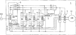
The electric device 1 of present embodiment can carry a plurality of battery units 2,3,4 respectively and to the charhing unit 8 of this each batteries 2B, 3B, 4B charging usefulness with mounting and dismounting on the apparatus main body (not shown).
Each battery unit the 2,3, the 4th, identical formation is the incorporate in couples unit of storing mechanisms such as batteries 2B, 3B, 4B and EEPROM 11,12,13 difference.On the battery unit of each battery unit 2,3,4 and apparatus main body is packed portion's (not shown) into, carry out respectively as the installation and removal of following battery unit 2,3,4 with apparatus main body side electric on the bindiny mechanism that is connected with separates, connector Ba1, the Ba2, the Ba3 that are made up of paired terminal respectively are set, connector Bb1, Bb2, Bb3, and connector Bc1, Bc2, Bc3.
And then, main body side at this electric device 1, have the controlling organization 6 of the overall action of control electric device 1, control power supply 7 that is attached thereto and driving mechanism 9, drive by this driving mechanism 9, drive the motor even load 10 of unillustrated running part, and be plugged in from three switch SW 11, SW12, the SW13 of each battery unit 2,3,4 to discharge (power supply) circuit of controlling organization 6 and driving mechanism 9.
And the charging mechanisms 5 in the charhing unit 8 have the charging controlled function of batteries 2B, 3B to each battery unit 2,3,4,4B and the information of each storing mechanism 11,12,13 are read and write-in functions.In addition, controlling organization 6 wherein except overall signal controlling function, has the information of the storage part 11,12,13 of each battery unit 2,3,4 is read and write-in functions too.
Though Fig. 1 illustrates the example that carries three battery units, just can realize purpose of the present invention as long as carry two above battery units.In addition, though because charhing unit 8 also can carry the main body of electric device 1 with mounting and dismounting, so also can easily take out, outside electric device 1, also can use, but also can be located at regularly on the main body of electric device 1 from electric device 1.
Batteries 2B, the 3B of each battery unit 2,3,4,4B respectively can storage batteries or a plurality of being connected in series of secondary cell obtain.
In each storing mechanism 11,12,13 of each battery unit 2,3,4, store the distinctive information of battery such as rated capacity, temperature characterisitic, preservation characteristics of each batteries 2B, 3B, 4B, with the information of the charging and discharging situation of relevant batteries such as charge volume, discharge capacity, charging and discharging number of times.
So, because each battery unit 2,3,4 has intrinsic information respectively, so the installation and removal of a plurality of each battery unit 2,3,4 are all no problem by which type of order.Be located at switch SW 11, SW12, SW13 SW1n control signal in each supply line between each battery unit 2,3,4 and controlling organization 6 and the driving mechanism 9 by controlling based on the controlled function of controlling organization 6, be switched on (ON) selectively, be used to use of the selection of which battery unit to controlling organization 6 and driving mechanism 9 power supplies.
And then, also carry out the information of each battery unit of being carried as required, for example other or the overall remaining capacity of a plurality of battery unit of the battery unit that is carried, or in the demonstration of the occasion charging requirement that the battery unit that needs charging is arranged etc. or alarm etc.That is to say that this controlling organization 6 has based on the information in the storing mechanism 11,12,13 that is stored in each battery unit 2,3,4, carry out the overall management of the control of connection/cut-out of control switch SW11, SW12, SW13 and electric device 1 and the function of control.
In addition, this control power supply 7 is in the taking-up of each battery unit 2,3,4 or when the halt instruction etc. of electric device 1 is arranged, to controlling organization 6 supply capabilities, up to controlling organization 6 driving of the load 10 that driving mechanism 9 carries out is stopped, the information such as charging and discharging situation of the batteries of working in the battery unit 2,3,4 are write storing mechanism in each battery unit, and the safety that finishes electric device 1 stops etc. till the necessary processing.
Driving mechanism 9 receives separately or as required the supply of the electric power of their combinations, carries out the driving and the control of motor or actuator, lamp ﹠ lantern even load 10 from a plurality of battery units 2,3,4 that are equipped on electric device 1.
Running parts such as the unillustrated wheel of motor driven of load 10 travel electric device 1.Actuator makes actions such as brake.Lamp ﹠ lantern is lamps such as headlight, taillight or side marker light.
In addition, in the occasion that is necessary to detect charging current or discharging current according to purpose, though do not draw, but for example on the position that can detect charging and discharging, current detecting mechanism is set, obtains the definite information of charging current and/or discharging current whereby at connector Ba2, the Bb2 of battery unit 2,3,4, the connection line of Bc2 etc.
Equally, characteristic according to the batteries of in each battery unit 2,3,4, using, by the voltage detection mechanism of the overall voltage of a plurality of battery cells of detection or this battery pack is set, or detect the temperature testing organization of the overall temperature of battery cell or this battery pack, can obtain at each batteries 2B, 3B in each battery unit 2,3,4, definite voltage or the temperature information of 4B.For these each testing results also can be mounted and dismounted with respect to apparatus main body with each battery unit 2,3,4, need the bindiny mechanism of its holding wire.
Next, the charging action to the battery unit in the electric device shown in this Fig. 12,3,4 describes.
If source power supply 100 or replace its power supply to be fed to the charging mechanism 5 of charhing unit 8, enter the charging action, each storing mechanism 11,12,13 in a plurality of each battery unit 2,3,4 of the microcomputer of charging mechanism 5 visit at first then, whether detect it packs into, and read the information that obtains in the storing mechanism that is stored in the battery unit of being packed into, just this information storage that obtains is remained in the memory that this charging mechanism 5 has if necessary.
Whereby, charging mechanism 5 is understood batteries 2B, the 3B of each battery unit 2,3,4 of the electric device 1 of packing into, the information such as charging and discharging situation of 4B.Then,, select the battery unit of fast end of for example charging, make some connections of switch SW 21~SW23, enter the charging action of batteries of the battery unit of selection by the SW2n signal according to the information of each battery unit 2,3,4 of this understanding.
If the charging of this battery unit finishes, charge information such as temperature writes the storing mechanism of the battery unit that this charging is through with, the next charging that needs the battery unit of charging of beginning during then the increase of charging times, full charge information, accumulative total charge volume, charging.Charging proceeds to till the battery unit that does not need to charge in a plurality of battery units that carried, and these complete charge actions are just finished.
In addition, even the occasion of ending to charge action midway for certain reason in charging, also because same when finishing with charging, being stored in the storing mechanism set in this battery unit that is charging, so when the charging and discharging of this battery unit, can utilize this information up to midway charge information.With regard to above-mentioned charging action, describe with the flow chart of Fig. 7 and Fig. 8.
If the charging mechanism 5 of the charhing unit among Fig. 18 enters the charging action described in the flow chart of Fig. 7 and Fig. 8, then at first as shown in Figure 7, visit the storage device (storing mechanism 11 of battery unit 2 in this example) of the battery unit of the 1st position of packing into, read in the information (data) that is stored in the there.
Then, judge whether these data are normal.Here, circuit is constituted to be unkitted fashionable data at battery unit be zero entirely.In this occasion, also can utilize the mechanism that for example is provided with and confirms to check sum data.
If whether normal data judged results normal (being) then be provided with show pack into the sign of the 1st position of battery unit, undesired if (denying) then do nothing, then visit the storage device (storing mechanism 12 of battery unit 3 in this example) of the 2nd position, read in the information (data) that is stored in the there.
Then, judge whether these data are normal.Normal if (being) then be provided with and show pack into the sign of the 2nd position of battery unit, undesired if (denying) then the ground of doing nothing, then visit the storage device (storing mechanism 13 of battery unit 4 in this example) of the 3rd position, read in the information (data) that is stored in the there.
Then, judge whether these data are normal.If normal (being) then pack into behind the sign of the 3rd position in that battery unit is set enters the processing of the charging shown in Fig. 8.
If the result whether data are judged normally is undesired (denying), then check and whether be provided with the sign of packing into, if were provided with because battery unit would be packed into the 1st and/or the 2nd position, so enter the processing of the charging shown in Fig. 8, if but be not provided with, then judge into which position battery unit of also not packing into of packing into, complete charge action here.
Move from the charging shown in Fig. 8, at the sign of packing into a plurality of occasions is arranged at battery unit, based on the information that obtains from each storing mechanism (information of the charging and discharging situation of relevant batteries), select the battery unit of fast end of for example charging, by the SW2n control signal, switch SW 21, SW22, SW23 in the charhing unit 8 shown in the control chart 1 are connected to this battery unit.Whereby, the batteries of the battery unit of selection begins charging.
After beginning charging, though the short of charging halt instruction of ending this charging halfway (cut-out of source power supply or based on the instruction from the charging shut-down operation of unillustrated operation board etc.) just continues charging, proceeding to the full charging finished of charging is normal charging method, but the charge information that charges so far is write the storing mechanism of the battery unit of selecting charging when sending the charging halt instruction halfway and complete charge is moved.
On the other hand, if the batteries of the battery unit of selecting begins charging, then in this charging, lean on the charging controlled function of charging mechanism 5, charge information such as temperature stores maintenance by the storing mechanisms in the charhing unit 8 when being necessary to measure with predetermined accumulative total charge volume of computing or charging with predetermined method according to the battery behavior of the battery unit of selecting.
Then, if the charging of the battery unit of selecting is finished, then its charge information is write the storing mechanism of selected battery unit.Then remove the sign of packing at this battery unit.
Then, judge whether other signs of packing into are provided with, if (if being eliminated) is not set then the complete charge action.But, still be provided with when sign (when not being eliminated) of packing into here, be restored to the initial step of Fig. 8, repeat above-mentioned processing, select charging in remaining battery unit the battery unit (battery unit of No. 2 charging) of fast end begin charging.Later processing is same with the passerby that battery unit advances who charges at No. 1.
After finishing the charging of this battery unit, when the sign of packing into that also has other battery units is set up, repeat the charging that the batteries of all battery units is finished in same action.
Though be certain thing, according to information, do not need the occasion of the charging of batteries not enter the charging action from the storing mechanism of each battery unit, only remove and pack sign into and finish processing at the battery unit of object.Whereby, can prevent just charging back or under fully charged state, charge once more and make to overcharge and flow through the batteries that does not need the battery unit that charges.
Here, as the information that is stored in the storing mechanism 11,12,13 that is located on each battery unit 2,3,4, be to use the information of relevant charging and discharging situation necessary on the characteristic of the characteristic of battery (batteries 2B, 3B, 4B) and electric device 1, temperature etc. when temperature, discharge time, accumulated discharge amount, remaining capacity, discharge when for example charging times, full charge information, accumulative total charge volume, charging are arranged.Details about this information is hereinafter addressed.
Next, just the action the during work (driving of load 10) of the electric device 1 shown in Fig. 1 describes.
Three place's battery units of electric device 1 at least one place of portion of packing into if battery unit is packed into then supplies with required power supply from control power supply 7 to controlling organization 6.
If power supply supplies to controlling organization 6, then the controlled function visit that has by controlling organization 6 is located at the storing mechanism 11,12,13 on each battery unit 2,3,4, controlling organization 6 is obtained the information of the required storing mechanism of the discharge of the battery unit whether battery unit pack into and packed into, and the information storage function that has by controlling organization 6 stores and keeps them as required.
By this action, same with aforementioned occasion by charging mechanism 5, understand the battery unit of the electric device 1 of packing into.Though do not draw, if the job requirement signal of electric device 1 is input to controlling organization 6, then controlling organization 6 is selected for example minimum battery unit of remaining capacity according to the needed information of above-mentioned discharge that obtains and keep.In fact, though according to the characteristic of batteries or the characteristic of electric device, the battery unit that selection is discharged describes with the example of selecting the minimum battery unit of remaining capacity in this example.
Then, come diverter switch SW11, SW12, SW13 by the SW1n control signal, according to above-mentioned requirements signal is delivered to driving mechanism 9, for example motor (not shown) that driving mechanism 9 drives as load 10 makes electric device work.
If Fang Dian battery unit becomes predetermined discharge done state selectively, then controlling organization 6 writes discharge information the storing mechanism of this battery unit.Then, according to from the information of the storing mechanism of other battery units of being packed into or the information that has obtained and stored, select the battery unit of next discharge, with the above-mentioned SW11 of diverter switch similarly, SW12, SW13, the battery unit that connects this selection cuts off the battery unit discharged.
In addition, even the occasion that disappears by the job requirement of the electric device 1 of driving mechanism 9 in discharge midway, discharge information also is written into the storing mechanism of the battery unit that is using.
Action when with the flow chart of Fig. 9 and Figure 10 this electric device being worked describes.
Consequently normal if (being) then the memory block of the information storage of the 1st storing mechanism in regulation.Same with explanation in charging action, in this occasion also be, also the sign of packing into can be set, whenever the information of storing mechanism for need occasion just visit the storing mechanism of this battery unit.
Result in above-mentioned judgement is the storing mechanism (storing mechanism 12 of battery unit 3 in the example of Fig. 1) of occasion zero access the 2nd position of undesired (denying), reads in its information.After the occasion of normal (being) was carried out above-mentioned processing, the storing mechanism (storing mechanism 12 of battery unit 3 in the example of Fig. 1) of then visiting the 2nd position was read in its information.Then, judge that it is normal data (information).
Result in this judgement is the storing mechanism (storing mechanism 13 of battery unit 4 in the example of Fig. 1) of occasion zero access the 3rd position of undesired (denying), reads in its information.Behind the memory block that the occasion of normal (being) is being stipulated the information storage of the 2nd storing mechanism, the storing mechanism (storing mechanism 13 of battery unit 4 in the example of Fig. 1) of then visiting the 3rd position is read in its information.Then, judge that it is normal data (information).
If the result of this judgement is normal (being), then, enter the work disposal shown in Figure 10 the memory block of the information storage of the 3rd storing mechanism in regulation.
Result in above-mentioned judgement is the occasion of undesired (denying), whether judgement has store information in the memory block of regulation, if have then enter the work disposal shown in Figure 10, if but not then judge into the 1st to the 3rd each battery unit of all not packing into of packing in the position, do not finish this processing here.
The processing of the initial step of Figure 10, relatively be stored in the content of the information in the memory block of regulation, select for example minimum battery unit of remaining capacity,, the battery unit of this selection is connected to controlling organization 6 and driving mechanism 9 by SW1n control signal control switch SW11, SW12, SW13.
Then, the batteries of the battery unit of this selection is discharged and supply capability, drive load 10 according to job requirement and make electric device 1 work.The batteries of this battery unit has remaining capacity, this battery unit continuous discharge duration of job requirement.When job requirement disappears, discharge information so far is write the storing mechanism of battery unit of selection after, end process.
In addition, if select battery unit and begin discharge, temperature etc. when then measuring the predetermined accumulated discharge amount of union necessity and discharge according to battery behavior and electric device characteristic with predetermined method by the controlled function of controlling organization 6 in this discharge stores by the information storage function of controlling organization 6 and to keep it.In addition, write the storing mechanism of this selected battery unit as required.
On the other hand, no matter whether this job requirement continues, the battery unit of way selection therein becomes storing mechanism and other storing mechanisms in case of necessity, for example storing mechanism of using in the information storage function that controlling organization 6 has that when discharging the state that finishes discharge information so far is stored in the battery unit of this selection.
Then, inspection is stored in the information in the memory block of aforementioned regulation, judge to have and do not have other battery units that can discharge, occasion end process ' denying ', but when ' being ', turn back to the initial step of Figure 10, repeat above-mentioned processing, in other battery units of being packed into, select the few battery unit of next remaining capacity to make it discharge, the load of job requirement drive is being arranged.
To be expression take out charhing unit 8 and a plurality of battery unit 2,3,4 and the figure of the connection status of the occasion of charging from the electric device shown in Fig. 11 Fig. 4, and it is same that its charging action is moved with aforementioned charging under the state that is equipped on the electric device 1.
Though illustrate in this example charhing unit 8 and three Battery pack unit 2,3,4 are taken out and the state of charging from electric device 1 simultaneously, there is no need necessarily a plurality of battery units that are equipped on electric device 1 all to be taken out simultaneously and charge.
For example, if in being equipped on a plurality of battery units of electric device 1, only the battery unit that the remaining capacity of the battery unit of discharge end or batteries is reduced takes out with charhing unit 8 and charges, and then can use remaining battery unit to make load 10 work according to job requirement till carrying this battery unit again.
In addition, charhing unit 8 is being located on the electric device 1 regularly, carry out the occasion of the charging of battery unit with the state that is equipped on electric device, because be necessary this charhing unit 8 is connected to source power supply 100, so have to electric device 1 itself is stopped at the place that can be connected to source power supply 100, can't use when charging.Thereby, have to charge in obsolete time periods such as nights.
But, if as present embodiment, can both be equipped on the main body of electric device 1 to any one of charhing unit 8 and battery unit 2,3,4 with mounting and dismounting, only charhing unit 8 and the battery unit that needs charging are taken out and charge from electric device 1, then there is no need an electric device 1 and be connected to source power supply, also can use remaining battery unit to drive load as mentioned above even charging, freely travel.
Though but the not shown charhing unit that can mount and dismount pack into freely this charhing unit 8 and one or more battery units portion and the battery unit portion of packing into of packing into integrally is set with this charhing unit 8, preparation is provided with the charging frame of the connecting line of receiving source power supply, packs into and is provided with that to constitute charhing unit 8 just passable with the fixed terminal (with being connected corresponding to charhing unit 8 each terminal with battery unit 2 grades) that battery unit 2 grades are electrically connected the connector of usefulness in the portion respectively at pack into portion and battery unit of this charhing unit.
So, only this charging of wearing or featuring stage armour is connected to source power supply with the connecting line of frame, the charhing unit 8 charhing unit portion of packing into of packing into, just can finish being connected between each connector between charhing unit 8 and the battery unit of packing into to the battery unit battery unit portion of packing into of packing into fully, begin charging immediately.
Use frame by this charhing unit 8 and charging, can constitute according to charging device of the present invention.Do not carry occasion in electric device at charging device, can be integrated and constitute charging device with frame charhing unit 8 and charging.
(the 2nd embodiment)
Fig. 2 is the square circuit diagram of electric device of the battery-mounted unit of expression the 2nd embodiment of the present invention, gives same label and omits or simplify explanation to them for the part identical with Fig. 1.
The battery unit 22,23,24 of this 2nd embodiment respectively with the battery unit of the 1st embodiment similarly, integrated in couples the storing mechanism 11,12,13 of the information of relevant its charging and discharging situation of batteries 2B, 3B, 4B and storage, and respectively dress and Fig. 1 be located at the same charging mechanism 25,26,27 of charging mechanism 5 on the charhing unit 8.Thereby the battery unit 22,23,24 of this occasion also can be called power subsystem.
And each battery unit 22,23,24 can be equipped in the main body of electric device 1 with mounting and dismounting.On the battery unit of this each battery unit 22,23,24 and apparatus main body is packed portion's (not shown) into, as the installation and removal of following battery unit 22,23,24 and respectively with the electric contact and the bindiny mechanism that separates of apparatus main body, connector Ca1, the Ca2, the Ca3 that are made up of paired terminal respectively are set, connector Cb1, Cb2, Cb3, connector Cc1, Cc2, Cc3.
The electric device 1 of present embodiment is adorned a plurality of battery units 22,23,24 of charging mechanism in carrying respectively, so do not carry the charhing unit 8 among Fig. 1.Other formation, just having controlling organization 6, control power supply 7, come the driving mechanism 9 of drive motor even load 10 according to the requirement of controlling organization 6, and by switch from the SW1n control signal of controlling organization 6 be same on three switch SW 11 using of the battery unit of discharge (power supply), SW12, the SW13 this point with the 1st embodiment.
The charging mechanism 25,26,27 of each battery unit 22,23,24 directly is connected with source power supply 100 respectively, and, constitute respectively with reference to the information in the storing mechanism 11,12,13 that is stored in, the batteries 2B in same unit, 3B, 4B charge same the unit in.Though the example that carries three Battery pack unit is shown, just passable more than carrying two groups.
Next, describe with regard to the action of the charging in the electric device of present embodiment.
If source power supply 100 or replace its power supply to be fed to the charging mechanism 25,26,27 of a plurality of battery units 22,23,24 then enter the charging action.
At first, each battery unit 22,23,24 is visited the storing mechanism 11,12,13 in the same unit respectively, read and be stored in each batteries 2B, the 3B that needs charging, the information among the 4B, need charge then this batteries is begun to charge if judge into batteries same unit in.Then, when this batteries becomes full charging, this charge information is write storing mechanism in the same unit and the complete charge action.
In addition, when the charging action was cut off in charging midway, the occasion that finishes with charging similarly write storing mechanism in the same unit to charge information so far, can utilize this information when making later charging and discharging.
Above-mentioned charging action is the example that a plurality of battery units 22,23,24 carry out charging process respectively independently.Yet if charge simultaneously in a plurality of battery units, to source power supply 100 or replace the electric power that requires of its power supply to strengthen, for example the occasion at domestic power supply exists the possibility that produces the such problem of circuit breaker group tripping operation.
As the means that address this is that, illustrate with Figure 12 as described later, 25,26,27 of charging mechanisms that have respectively at each battery unit 22,23,24 couple together with unillustrated connector and holding wire, each charging mechanism 25,26,27 leans on the information exchange of this holding wire by way of giving mutually and receiving information, determine the order of accumulators group 2B, 3B, 4B charging, it also is possible being controlled to the order charging.
The content of the information that has according to each storing mechanism 11,12,13 how, can prepare required source power supply or replace its power supply, or be taken as with source power supply or replace the electric power of power capacity balance of its power supply to require and carry out the order charging, the charge volume of perhaps controlling a plurality of batteries 2B, 3B, 4B is corresponding with it.
On the other hand, in the present embodiment, owing in each battery unit 22,23,24, connecting batteries 2B, 3B, 4B and charging mechanism 25,26,27 respectively all the time, so be necessary between batteries and charging mechanism, but, seek to prevent the adverse current to the electric current of charhing unit 25,26,27 from batteries 2B, 3B, 4B though not shownly can plug for example diode or reverse current prevention circuit etc.
Next, with the charging action in above this electric device that illustrates of flow chart detailed description of Figure 11 and Figure 12.
According to the charging action of the flow chart of Figure 11, charge the independently respectively situation of action of the charging mechanism 25,26,27 of each battery unit 22,23,24 shown in Fig. 2 is arranged.
If source power supply 100 or replace its power supply to supply to the charging mechanism 25,26,27 of each battery unit 22,23,24, then this each charging mechanism 25,26,27 enters the charging action shown in the flow chart of Figure 11.Though all carry out same action in any one battery unit, the occasion with battery unit 22 is that example describes below.
In battery unit 22, charging mechanism 25 is at first visited storing mechanism 11, judges whether its data are normal.In normal occasion, judge the necessity of the charging of batteries 2B according to the information that obtains from this storing mechanism 11.Then, if judging to become to need charges, then begin the charging of batteries 2B.The halt instruction of short of this charging in back of beginning to charge just continues charging, and whether judging charges finishes, if finish, then at that time charge information is write storing mechanism 11 and complete charge is moved.
Begin the charging action, do not charge action as makeing mistakes when the result of visit storing mechanism 11 is not normal data.In this occasion, after investigating its reason etc. and disposing, entering the charging action again.In addition, the result of necessity who judges the charging of batteries 2B according to the information that obtains from storing mechanism judges when becoming needs charging complete charge action there.
On the other hand, have after beginning to charge when charging the instruction that stops,, also charge information so far is write storing mechanism 11 and the complete charge action midway even in charging.
, if carry out above-mentioned this charging action simultaneously in a plurality of battery units, then as illustrating, require electric power too to strengthen, the circuit breaker group that is located at sometimes in the supply line of source power supply 100 trips.
In order to prevent the generation of this problem, it is just passable to carry out the order charging shown in the flow chart of Figure 12.
In this occasion, the approach that can give mutually and receive information is set between the charging mechanism 25,26,27 of each battery unit 22,23,24 that is equipped on electric device 1 shown in Fig. 2.Then, each charging mechanism 25,26,27 exchanges the information that obtains from storing mechanism 11,12,13 respectively, can at random determine the charging order of each batteries 2B, 3B, 4B.
For example, the information that obtains based on from each storing mechanism is arranged, obtain the charging necessary amount, carry out time conversion and calculate the necessary charging interval, from the method for short batteries order charging of its necessary charging interval according to the remaining capacity of each batteries.In addition, also have method, perhaps irrespectively give method to the battery charging of battery unit by predetermined order with the size of remaining capacity by few (discharge at most) the order charging of the remaining capacity of each batteries.And then, also have the method that begins the order charging from the big batteries of the charging capacity of time per unit.
In the example shown in the flow chart of Figure 12, in initial step, the charging mechanism 25,26,27 of each battery unit 22,23,24 of being packed into and the charging mechanism of other battery units carry out giving and accepting of information mutually, understand number, the necessity that obtains charging and the information in charging interval of the battery unit of being packed into respectively.
Then, judge the number of the battery unit that needs charging.In the result of this judgement, the number that needs the battery unit of charging is 3 occasion, and a side short from the charging interval selects two battery units, and its each batteries is begun charging.At the battery unit number of needs chargings is not 3 occasion, begins the charging of this battery unit that need charge.
Then, each charging mechanism 25,26,27 also carries out and the giving and accepting of the information of other battery units all the time in charging, obtains the up-to-date information of the charging and discharging situation of relevant batteries mutually.
If the charging halt instruction is arranged in charging, the charging mechanism of the action of then charging writes the storing mechanism of same unit to charge information so far, and complete charge is moved.
Short of charging halt instruction just continues the charging action, judges whether to finish charging.If the result of this judgement does not finish, then one side is carried out giving of information and is accepted to continue the charging action on one side between each charging mechanism.
Finished charging if having, the charging mechanism of then having finished the battery unit of charging writes the charge information that had at that time the storing mechanism of same unit.
Then, based on mutual the giving and receiving information of each charging mechanism, further whether judgement needs the battery unit that charges, if whether the number that has then turn back to the battery unit that needs charging is 3 judgement, repeat above-mentioned charging action, needs the charging of the batteries of the battery unit that charges.
Then, after finishing this charging, the result who needs charging person's judgement whether is the occasion of ' denying ', judges that the charging of the batteries of all battery units that need is in pairs finished, the complete charge action.
Next with the limit procedure among this 2nd embodiment of flow chart explanation of Figure 13 and Figure 14 about the charging power (charge volume) of charging power control.
In the battery of in constant current charge, detecting as Ni-Cd battery or Ni-MH battery-Δ V or Δ V (high accuracy) peak value, it is difficult suppressing charging current and reducing charging power, but constant voltage constant current charge battery as lithium ion, excide battery reduces charging current and reduces charging power and become easy.
Therefore, in the example of following explanation, can distinguish the kind of battery and suppress charging current (electric power), and then make the detection of charging voltage and charging current become possibility, have the function of calculating charging power.
If the charging power control action shown in each charging mechanism 25,26,27 usefulness source power supplies 100 beginning Figure 13 of a plurality of battery units 22,23,24, then at first pack into the charging mechanism of each battery unit of electric device 1 and the charging mechanism of other battery units carries out giving and accepting of information, obtains the necessity of charging of each battery unit of being packed into and the information in charging interval.
Then, whether need the judgement of the battery unit that charges, when the battery unit that does not need to charge, finish the charging action of all battery units.
When the battery unit that needs charging is arranged, the shortest battery unit of charging interval be no more than from the electric power amount of source power supply, and in the scope of the maximum capacity of charging mechanism, begin charging.
Here the electric power amount of source power supply can be obtained according to the efficient of for example charging voltage and charging current and charging mechanism.Back each charging mechanism of a plurality of battery units that begins to charge comprises the giving and accepting of charge information of the electric power amount of source power supply by its charging controlled function.Then shown in Figure 14 up to the processing that finishes, if owing to repeat above-mentioned processing then carry out and the same processing of occasion, so omit its explanation with the order charging of Figure 12 explanation.
As above explanation, in the present embodiment, all the time carry out giving and accepting of charge information between each charging mechanism 25,26,27, grasp the charge information of all battery units that carried whereby respectively, when batteries 2B, the 3B of each battery unit 22,23,24, some chargings among the 4B are finished, all the time judge to have do not have the next battery unit that needs charging perhaps therein on the way.
Then, when they were arranged, next short battery unit of charging interval was no more than the electric power amount from source power supply 100, and begins charging in the maximum capacity of charging mechanism.
That is to say that the charging mechanism of each battery unit is grasped the charge information of the charging mechanism of other all battery units respectively mutually, can grasp each whereby to source power supply 100 desired total electricities.
By the grasp of this total electricity, each charging mechanism is adjusted the charging power of oneself, makes all the time the ability at source power supply 100 become possibility with interior parallel charging.
For example as lithium ion battery, concerning the occasion of the battery that charges in constant current constant voltage mode, have from constant current, charging power is little when voltage is low, rising charging power increase along with voltage, charging power becomes maximum when entering constant voltage mode under the voltage of defined, reduces such characteristic because of charging current reduces charging power later on.
The characteristic of utilizing this required charging power to change along with charged state makes each charging mechanism action with whole permission electric power of source power supply, and the charging that efficient is high becomes possibility whereby.Though these are descriptions of the battery that just charges in constant current constant voltage mode, even have the battery of other characteristics, also can obtain same effect certainly by the grasp and the charging control of its characteristic.
Though in Figure 13 and example illustrated in fig. 14, be taken as batteries order charging since the shortest battery unit of charging interval, but also can be altered to these from the big battery unit charging of charging power, perhaps from little battery unit charging of charging power etc.In any case, by determining can to realize its purpose at the charging order of the characteristic of the battery behavior of batteries or electric device.
Be through with like this to the battery unit of battery charging, at this moment its charging mechanism writes its storing mechanism to charge information by the charging controlling organization and waits by the time the charging of all battery units finishes, and finishes by all chargings, and the charging action is finished.In addition, cut-out by source power supply or charging shut-down operation are charged when being stopped, and having begun the battery unit of charging action and aforementionedly similarly charge information so far are write each storing mechanism and finish.
To be expression take out the Battery pack unit among Fig. 2 and the figure of the charging method of the occasion that the accumulators group is charged from electric device 1 Fig. 5, and the example of battery unit 22 is shown.Be with the charging method difference on the aforementioned electric device 1, not to charge in proper order to each batteries of a plurality of battery units, but respectively each battery unit 22,23,24 is taken out from electric device 1, its charging mechanism 25,26,27 is connected to source power supply 100, charge monolithically for its batteries 2B, 3B, 4B respectively, be equipped on electric device 1 again.
In addition, in the occasion of taking out a plurality of battery units, when being equipped on electric device 1 similarly, if the charging mechanism of each battery unit connect each other in case charge information give and acceptance becomes possibility, even then when a plurality of battery units were connected to a source power supply conveying end, the parallel charging action in the permission electric power of this source power supply also became possibility.
If use present embodiment, then there is no need charhing unit is equipped on electric device, perhaps be equipped with charging device in addition, so long as source power supply, no matter wherein one by one battery unit ground give its battery charging.In addition, in the occasion of the battery charging of giving a plurality of battery units, can charge or easily carry out charging power control as mentioned above in proper order.
(the 3rd embodiment)
Fig. 3 is the square circuit diagram of electric device of the battery-mounted unit of expression the 3rd embodiment of the present invention, to giving same label with the equal part of Fig. 1, omits its explanation.
The battery unit 32,33,34 of the 3rd embodiment shown in this Fig. 3 is same with the battery unit of the 1st embodiment respectively, integrated in couples the storing mechanism 11,12,13 of the information of relevant its charging and discharging situation of batteries 2B, 3B, 4B and storage, and with batteries 2B, 3B, 4B switch SW a, SWb, SWc are set in series respectively.
These switches can be realized having both and be located at switch SW 21, SW22, SW23 and the switch SW of being controlled by controlling organization 6 11 in the charhing unit 8, the function of SW12, SW13 among Fig. 1, and the cost that can seek product reduces.
And these each battery units 32,33,34 can be equipped on the main body of electric device 1 with mounting and dismounting.This each battery unit 32,33,34 is respectively equipped with the control terminal of the series circuit of batteries 2B, 3B, 4B and switch SW a, SWb, SWc and this each switch SW a, SWb, SWc, and the terminal (terminal of the cell side separately of connector Ba1~Ba6, connector Bb1~Bb6 and connector Bc1~Bc6) that storing mechanism 11,12,13 is connected to outside usefulness.
And, on each battery unit of electric device 1 is packed portion into, be provided with the installation and removal of following each battery unit 32,33,34 and with the fixed terminal separately that is connected on above-mentioned each terminal is electric with the connector Ba1~Ba6 that separates, connector Bb1~Bb6 and connector Bc1~Bc6.
The electric device 1 of this 3rd embodiment carries above-mentioned a plurality of battery units 32,33,34, and can carry the charhing unit 18 that is provided with charging mechanism 5 with mounting and dismounting.And then, though having controlling organization 6, control power supply 7 and coming according to the requirement of controlling organization 6 on driving mechanism 9 this point of drive motor even load 10 with the 1st embodiment shown in Fig. 1 is same, does not have to be provided with switch SW 11, SW12, the SW13 that is controlled by controlling organization 6.
This charhing unit 18 is that the charhing unit 8 from Fig. 1 omits switch SW 21, SW22, SW23, respectively the SW control signal is individually outputed to three connector Cr1, Cr2, Cr3, three ground connection side-connector Cg1, Cg2, Cg3 among Fig. 1 are merged into a ground connection side-connector Cg1 person.
In the present embodiment, in each battery unit 32,33,34, switch SW a, SWb, SWc are set respectively, corresponding, the charging mechanism of charhing unit 18 5 is by based on the SW control signal of its charging controlled function switch SW a, SWb, the SWc in each battery unit 32,33,34 of open and close controlling individually respectively.
In addition, controlling organization 6 also is can lean on based on the SW control signal of its controlled function switch SW a, SWb, the SWc in each battery unit 32,33,34 of open and close controlling individually respectively.
Here, has relative importance value from the SW control signal of charging mechanism 5 with from the SW control signal of controlling organization 6 some, the occasion that for example has relative importance value at charging mechanism 5, detect and be connected to the true of source power supply 100 and this information is sent to controlling organization 6, by forbidding output, can guarantee the normal action of three switch SW a, SWb, SWc from the SW control signal of controlling organization 6.
In addition, be provided as the function of control power supply 7, supply with for the controlling organization 6 when certain battery unit carries carries out necessary electric power, the output of the batteries 2B that is not switched, the 3B of battery unit 32,33,34,4B is supplied to the connector circuit of control power supply 7 usefulness.
Charging action in the electric device of this 3rd embodiment, though each switch SW 21, SW22, SW23 in the charhing unit 8 among the 1st embodiment shown in Fig. 1 are being replaced as switch SW a, SWb, the SWc that is located at respectively in each battery unit 32,33,34, and be replaced as the SW2n control signal on the SW control signal this point different, but in addition with the 1st embodiment shown in Fig. 7 and Fig. 8 in charging action be same, so omit its explanation here.
Work (load driving) action that the electric device 1 of this 3rd embodiment carries out, though the switch SW shown in Fig. 1 21, SW22, SW23 are being replaced as switch SW a, SWb, the SWc that is located at respectively in each battery unit 32,33,34, and be replaced as the SW1n control signal among the 1st embodiment (Fig. 1) on the SW control signal this point different, but in addition the action with the electric device 1 of the 1st embodiment shown in Fig. 9 and Figure 10 is same, so omit its explanation here.
Fig. 6 illustrates charhing unit 18 and a plurality of battery unit 32,33,34 is taken out and the state of charging from the electric device shown in Fig. 31.Because this charging action is same with the charging action that the 1st embodiment that illustrates with Fig. 4 carries out, so omit its explanation here.
Moreover, in the battery unit 22,23,24 of the 2nd embodiment shown in Fig. 2 also be, on batteries 2B, 3B, 4B, be arranged to respectively in series to connect/to cut off control switch from the outside, can omit switch SW 11, SW12, SW13 whereby.
Claims (13)
1. an electric device is characterized in that,
On above-mentioned electric device main body, can be equipped with a plurality of battery units with mounting and dismounting, be provided with the storing mechanism of the batteries and the information of the charging and discharging situation that stores relevant this batteries at least in this battery unit in couples,
On the battery unit of this each battery unit and above-mentioned electric device main body is packed portion into, be provided with the installation and removal of following above-mentioned battery unit and carry out electric contact and the bindiny mechanism that separates with above-mentioned electric device main body,
On above-mentioned electric device main body, have: drive the driving mechanism of load, and control from the controlling organization of this each battery unit to the supply of the electric power of above-mentioned driving mechanism with reference to the information in the storing mechanism that is stored in above-mentioned each battery unit that is carried,
On above-mentioned electric device main body or above-mentioned each battery unit, with reference to the charging mechanism of the information in the above-mentioned storing mechanism that is stored in above-mentioned each battery unit to above-mentioned battery charging,
Above-mentioned charging mechanism have read having at least in the above-mentioned storing mechanism that is stored in above-mentioned each battery unit close above-mentioned batteries the charging and discharging situation information mechanism and in this storing mechanism, write to the mechanism of information of the charging and discharging situation of the above-mentioned batteries in the same unit, rare pass.
2. according to the electric device described in the claim 1, it is characterized in that,
Be respectively arranged with above-mentioned charging mechanism in above-mentioned each battery unit, this charging mechanism has the mechanism that information in the storing mechanism that cross-reference is stored in above-mentioned each battery unit that carries is determined charging order.
3. according to the electric device described in the claim 1, it is characterized in that,
In above-mentioned each battery unit, be respectively arranged with the switch that is connected in series with above-mentioned batteries,
Above-mentioned charging mechanism be arranged on the above-mentioned electric device main body and with reference to the information in the above-mentioned storing mechanism that is stored in above-mentioned each battery unit via above-mentioned switch to above-mentioned battery charging,
Above-mentioned controlling organization is controlled from the supply of above-mentioned batteries to the electric power of above-mentioned driving mechanism via the above-mentioned switch of this each battery unit with reference to the information in the storing mechanism that is stored in above-mentioned each battery unit.
4. according to the electric device described in the claim 1, it is characterized in that,
Above-mentioned charging mechanism constitutes on above-mentioned electric device main body the unit that is provided with and can mounts and dismounts with respect to this electric device main body.
5. according to the electric device described in the claim 3, it is characterized in that,
Above-mentioned charging mechanism constitutes the unit that can mount and dismount with respect to above-mentioned electric device main body.
6. according to any one the described electric device in the claim 1 to 5, it is characterized in that,
Above-mentioned controlling organization has the mechanism that the information of reading in the above-mentioned storing mechanism that is stored in above-mentioned each battery unit is controlled the overall action of above-mentioned electric device.
7. according to the electric device described in the claim 1 to 5 any one, it is characterized in that,
The above-mentioned storing mechanism of above-mentioned each battery unit also stores the information of the characteristic of closing above-mentioned batteries, above-mentioned charging mechanism has the information with reference to the characteristic that is stored in the relevant above-mentioned batteries in the above-mentioned storing mechanism of above-mentioned each battery unit, according to the mechanism of the charging of this this batteries of Characteristics Control.
8. according to any one the described electric device in the claim 1 to 5, it is characterized in that,
The above-mentioned storing mechanism of above-mentioned each battery unit also stores the information of the characteristic of closing above-mentioned batteries, above-mentioned controlling organization has the information with reference to the characteristic of the relevant above-mentioned batteries in the above-mentioned storing mechanism that is stored in above-mentioned each battery unit, according to the mechanism of this Characteristics Control from the discharge of this batteries.
9. according to any one the described electric device in the claim 1 to 5, it is characterized in that,
Above-mentioned controlling organization has based on the information that is stored in above-mentioned each battery unit, shows the remaining capacity of the batteries of this each battery unit, is having the occasion that needs the storage batteries group to carry out the mechanism of the demonstration and/or the alarm of charging requirement.
10. the charging and discharging method of the battery unit in the electric device, this electric device can be equipped with a plurality of battery units with mounting and dismounting, the storing mechanism of the ground batteries and the information of the charging and discharging situation that stores relevant this batteries at least is set in this battery unit in couples, has the driving mechanism that drives load, control is from the controlling organization of above-mentioned each battery unit to the supply of the electric power of above-mentioned driving mechanism, and to the charging mechanism of the above-mentioned battery charging of above-mentioned each battery unit, the method is characterized in that
Above-mentioned controlling organization is controlled above-mentioned charging mechanism, discharge and recharge with reference to the relevant above-mentioned information that discharges and recharges situation that is stored in the above-mentioned storing mechanism, simultaneously, at least the information of the situation that discharges and recharges of the above-mentioned batteries in the relevant same battery unit is write in the above-mentioned storing mechanism.
11. the charging and discharging method according to the battery unit in the electric device described in the claim 10 is characterized in that,
Utilize above-mentioned controlling organization and above-mentioned charging mechanism, with reference to the relevant above-mentioned information that discharges and recharges situation that is stored in the above-mentioned storing mechanism, the above-mentioned batteries of above-mentioned each battery unit that carries, press the many sequence discharges of remaining capacity, press the few order charging of remaining capacity.
12. the charging and discharging method according to the battery unit in the electric device described in the claim 10 is characterized in that,
Utilize above-mentioned controlling organization and above-mentioned charging mechanism, with reference to the relevant above-mentioned information that discharges and recharges situation that is stored in the above-mentioned storing mechanism, the batteries of above-mentioned each battery unit that carries, press the few sequence discharge of remaining capacity, just charging when remaining capacity is lower than setting.
13. the charging and discharging method according to the battery unit in the electric device described in the claim 10 is characterized in that,
Utilize above-mentioned controlling organization and above-mentioned charging mechanism, with reference to the relevant above-mentioned information that discharges and recharges situation in the above-mentioned storing mechanism that is stored in above-mentioned each battery unit that carries, select one or more above-mentioned battery units to make its each batteries discharge, select remaining one or more above-mentioned battery unit its each battery charging.
Applications Claiming Priority (2)
| Application Number | Priority Date | Filing Date | Title |
|---|---|---|---|
| JP220503/99 | 1999-08-03 | ||
| JP22050399A JP3890168B2 (en) | 1999-08-03 | 1999-08-03 | Electric device and charging / discharging method of battery unit thereof |
Publications (2)
| Publication Number | Publication Date |
|---|---|
| CN1369127A CN1369127A (en) | 2002-09-11 |
| CN1237681C true CN1237681C (en) | 2006-01-18 |
Family
ID=16752065
Family Applications (1)
| Application Number | Title | Priority Date | Filing Date |
|---|---|---|---|
| CNB008111634A Expired - Fee Related CN1237681C (en) | 1999-08-03 | 2000-07-31 | Electric device and apparatus for charging battery unit, and method for charging and discharging |
Country Status (8)
| Country | Link |
|---|---|
| US (1) | US6741065B1 (en) |
| EP (1) | EP1223653B1 (en) |
| JP (1) | JP3890168B2 (en) |
| KR (1) | KR100452566B1 (en) |
| CN (1) | CN1237681C (en) |
| CA (1) | CA2380959C (en) |
| DE (1) | DE60033833T2 (en) |
| WO (1) | WO2001011754A1 (en) |
Cited By (3)
| Publication number | Priority date | Publication date | Assignee | Title |
|---|---|---|---|---|
| CN102148513A (en) * | 2010-02-08 | 2011-08-10 | 三菱重工业株式会社 | Power feeding device and rubber tired gantry crane including the same |
| CN102738844A (en) * | 2011-04-15 | 2012-10-17 | 郑茂振 | Line-interactive power control system |
| CN103026581A (en) * | 2010-07-29 | 2013-04-03 | 三菱重工业株式会社 | Battery system for moving body, and method of controlling battery system for moving body |
Families Citing this family (186)
| Publication number | Priority date | Publication date | Assignee | Title |
|---|---|---|---|---|
| US20030209375A1 (en) * | 1999-01-25 | 2003-11-13 | Zip Charge Corporation | Electrical vehicle energy supply system, electrical vehicle battery, electrical vehicle battery charging apparatus, battery supply apparatus, and electrical vehicle battery management system |
| US6977482B2 (en) | 2003-02-11 | 2005-12-20 | O2Micro International Limited | Selector circuit for power management in multiple battery systems |
| US7348760B2 (en) | 2000-09-21 | 2008-03-25 | O2Micro International Limited | Power management topologies |
| US7564220B2 (en) | 2000-09-21 | 2009-07-21 | O2Micro International Ltd. | Method and electronic circuit for efficient battery wake up charging |
| US7193393B1 (en) * | 2001-10-26 | 2007-03-20 | Payne James C | Approach for charging multiple batteries |
| JP3886389B2 (en) | 2002-02-07 | 2007-02-28 | 株式会社リコー | Battery pack charging device and charging method |
| TWI237916B (en) * | 2002-05-13 | 2005-08-11 | Sun Bridge Corp | Cordless device system |
| KR20040048221A (en) * | 2002-12-02 | 2004-06-07 | 엘지전자 주식회사 | Method for charging the many of battery |
| WO2004051785A1 (en) * | 2002-12-05 | 2004-06-17 | Matsushita Electric Industrial Co., Ltd. | Battery pack and its charging/discharging method |
| US20040217734A1 (en) * | 2003-04-30 | 2004-11-04 | Shum King Mo | Battery charger circuit |
| CA2539723A1 (en) * | 2003-09-22 | 2005-04-07 | Valence Technology, Inc. | Electrical systems, power supply apparatuses, and power supply operations methods |
| ES2668356T3 (en) | 2003-10-06 | 2018-05-17 | Powersys, Llc | Power generation systems and power generation methods |
| JP2005237064A (en) * | 2004-02-18 | 2005-09-02 | Autech Japan Inc | Vehicle controller |
| JP2005321983A (en) * | 2004-05-07 | 2005-11-17 | Sony Corp | Electronic equipment, battery pack, and power supply control method and program for electronic equipment |
| WO2005114811A2 (en) * | 2004-05-17 | 2005-12-01 | Railpower Technologies Corp. | Design of a large battery pack for a hybrid locomotive |
| US7091693B2 (en) * | 2004-06-29 | 2006-08-15 | M/A-Com, Inc. | Battery with non-volatile memory for LMR portable radio applications |
| US7345455B2 (en) * | 2004-11-18 | 2008-03-18 | International Business Machines Corporation | Staggered backup battery charging system |
| US7545121B2 (en) * | 2004-12-15 | 2009-06-09 | Bolduc Scott A | Auxiliary vehicle power supply |
| WO2006086987A2 (en) * | 2005-02-17 | 2006-08-24 | Reelight Aps | An electric converter system comprising storage media having different storing capacities |
| JP4613676B2 (en) * | 2005-04-12 | 2011-01-19 | 株式会社トヨトミ | Small household power supply |
| KR100713850B1 (en) * | 2005-09-28 | 2007-05-07 | 삼성전자주식회사 | Battery pack, portable electronic apparatus, and control method thereof |
| US7688029B2 (en) | 2005-11-08 | 2010-03-30 | Eveready Battery Company, Inc. | Portable battery powered appliance and method of operation |
| US20100001686A1 (en) * | 2006-01-24 | 2010-01-07 | Michael Steven Hargett | Electric vehicle battery alternating recharging process |
| WO2007100035A1 (en) * | 2006-03-03 | 2007-09-07 | Nec Corporation | Power supply system |
| JP4572850B2 (en) * | 2006-03-24 | 2010-11-04 | 株式会社日立製作所 | Power control device |
| US7605492B2 (en) * | 2006-04-21 | 2009-10-20 | Ford Global Technologies, Llc | Power supply system and method for supplying power to a vehicle |
| JP5022623B2 (en) * | 2006-04-27 | 2012-09-12 | 株式会社日立製作所 | Elevator system and battery unit |
| ES2368744T3 (en) * | 2006-05-11 | 2011-11-21 | Hoppecke Batterien Gmbh & Co. Kg | DISPOSITION OF ACCUMULATORS. |
| JP2008136278A (en) | 2006-11-27 | 2008-06-12 | Matsushita Electric Works Ltd | Charger |
| JP4727562B2 (en) * | 2006-12-12 | 2011-07-20 | 日本電信電話株式会社 | Charging method and charging circuit |
| JP4513812B2 (en) * | 2007-01-04 | 2010-07-28 | トヨタ自動車株式会社 | Vehicle power supply device and vehicle |
| JP4894559B2 (en) * | 2007-03-05 | 2012-03-14 | トヨタ自動車株式会社 | Power supply circuit control device |
| JP4491471B2 (en) * | 2007-03-23 | 2010-06-30 | Necフィールディング株式会社 | Uninterruptible power supply, uninterruptible power supply system, and uninterruptible power supply method |
| JP4680238B2 (en) * | 2007-06-11 | 2011-05-11 | トヨタ自動車株式会社 | Electric system charging apparatus and charging method |
| JP5268291B2 (en) * | 2007-06-18 | 2013-08-21 | 日立ビークルエナジー株式会社 | Battery unit device |
| JP5335207B2 (en) * | 2007-07-05 | 2013-11-06 | キヤノン株式会社 | Electronics |
| JP5118913B2 (en) * | 2007-07-24 | 2013-01-16 | トヨタ自動車株式会社 | Power supply system, electric vehicle equipped with the same, and control method of power supply system |
| US9579961B2 (en) * | 2007-09-24 | 2017-02-28 | Scott C Harris | Hybrid vehicle with modular battery system |
| JP4277928B1 (en) | 2007-12-07 | 2009-06-10 | トヨタ自動車株式会社 | vehicle |
| US8775828B2 (en) * | 2008-02-25 | 2014-07-08 | Gary Coonan | Power control system for mobile workstation and method |
| US7782607B2 (en) * | 2008-02-25 | 2010-08-24 | Stinger Industries LLC | Mobile workstation having power system with removable battery configured for drop-in engagement therewith |
| US8227943B2 (en) * | 2008-02-25 | 2012-07-24 | Lee Melvin Harbin | Power system retrofit kit for mobile workstation and retrofit method |
| US8160727B2 (en) * | 2008-02-25 | 2012-04-17 | Gary Coonan | Mobile workstation control system configured for power system and peripheral device control |
| US7855530B2 (en) * | 2008-02-25 | 2010-12-21 | Stinger Industries, Llc | Battery charging system and method of reducing variation in battery charging cycle count |
| US8169191B2 (en) | 2008-02-25 | 2012-05-01 | Werthman Dean A | System for use in gathering or processing data in a healthcare facility having fleet of mobile workstations |
| US7800255B2 (en) * | 2008-02-25 | 2010-09-21 | Stinger Industries LLC | Power system for mobile workstation and method |
| US7830668B2 (en) * | 2008-02-25 | 2010-11-09 | Stinger Industries LLC | Power supply unit for mobile workstation and method |
| JP4315232B1 (en) | 2008-03-17 | 2009-08-19 | トヨタ自動車株式会社 | Electric vehicle |
| US9007024B2 (en) * | 2008-05-28 | 2015-04-14 | American Reliance, Inc. | DC power control to maximize battery charging time |
| JP4577413B2 (en) * | 2008-06-20 | 2010-11-10 | トヨタ自動車株式会社 | vehicle |
| JP2010026941A (en) * | 2008-07-23 | 2010-02-04 | Hitachi Ltd | Storage system having a plurality of battery modules |
| JP4981973B2 (en) * | 2008-09-02 | 2012-07-25 | 三菱重工業株式会社 | Charging system for overhead line-less transportation system |
| JP4438887B1 (en) | 2008-09-26 | 2010-03-24 | トヨタ自動車株式会社 | Electric vehicle and charging control method for electric vehicle |
| JP2010098803A (en) * | 2008-10-15 | 2010-04-30 | Yunimekku:Kk | Dc/ac power source unit not influenced by noise superposed on supply power source |
| JP4811446B2 (en) * | 2008-10-21 | 2011-11-09 | トヨタ自動車株式会社 | Power supply system, vehicle equipped with the same, and control method of power supply system |
| US20100109603A1 (en) * | 2008-10-31 | 2010-05-06 | Michael Steven Hargett | Battery alternating recharging process |
| JP5187152B2 (en) * | 2008-11-17 | 2013-04-24 | トヨタ自動車株式会社 | Vehicle power supply system and vehicle |
| DE102008063213A1 (en) * | 2008-12-29 | 2010-07-01 | Conti Temic Microelectronic Gmbh | Energy storage arrangement for operation of pre-determined load on board system of internal-combustion engine of motor vehicle, has energy storage block subjecting predetermined load with supply voltage |
| US20100213897A1 (en) * | 2009-02-23 | 2010-08-26 | Lawrence Tze-Leung Tse | Battery-Cell Converter Management Systems |
| JP4576465B2 (en) * | 2009-03-06 | 2010-11-10 | 三菱重工業株式会社 | Charging method and charging system for overhead line-less traffic vehicle |
| JP5738519B2 (en) * | 2009-03-27 | 2015-06-24 | 伊藤忠商事株式会社 | Battery control device, vehicle, and battery control method |
| JP5476020B2 (en) * | 2009-03-30 | 2014-04-23 | 株式会社日本総合研究所 | Charging control system, battery pack, vehicle, and charging control method |
| US9537326B2 (en) * | 2009-04-16 | 2017-01-03 | Valence Technology, Inc. | Batteries, battery systems, battery submodules, battery operational methods, battery system operational methods, battery charging methods, and battery system charging methods |
| DE102009035483A1 (en) | 2009-07-31 | 2011-02-03 | Daimler Ag | Battery system operating method for use in e.g. hybrid vehicle, involves controlling switching-on and off process of battery units by controlling unit depending on operating characteristics of battery units |
| CN102577020B (en) | 2009-07-31 | 2016-01-20 | 热之王公司 | bi-directional battery voltage converter |
| SE534387C2 (en) * | 2009-09-01 | 2011-08-02 | Electroengine In Sweden Ab | A battery pack, a battery control device, a device comprising a battery control device and a battery pack, and a method of controlling a battery pack |
| TW201112146A (en) * | 2009-09-18 | 2011-04-01 | What Trend Technology Corp Ltd | Remote management system and method of secondary battery |
| CN102549877B (en) * | 2009-11-11 | 2015-11-25 | 美商源捷有限公司 | The interlock mechanism of many battery pack |
| WO2011095650A1 (en) * | 2010-02-04 | 2011-08-11 | Ecomotive Inova Consultores, S.L. | Electricity supply system for vehicles |
| JP5171974B2 (en) * | 2010-02-19 | 2013-03-27 | ヤマハ発動機株式会社 | Electric motorcycle |
| JP5415465B2 (en) * | 2010-03-11 | 2014-02-12 | 中国電力株式会社 | Charging system and charging method in charging system |
| JP5485752B2 (en) * | 2010-03-15 | 2014-05-07 | エスアイアイ・データサービス株式会社 | Battery charger, battery pack, and order entry terminal |
| US8427104B2 (en) | 2010-04-22 | 2013-04-23 | The Raymond Corporation | Method of allocating batteries for use on specific industrial vehicles in a fleet |
| KR101097272B1 (en) * | 2010-07-27 | 2011-12-21 | 삼성에스디아이 주식회사 | Battery pack and electric transfer means including same |
| CN102372197B (en) * | 2010-08-12 | 2014-08-13 | 上海三菱电梯有限公司 | Elevator control device |
| JP5679738B2 (en) * | 2010-08-26 | 2015-03-04 | 株式会社日立製作所 | Battery control device and vehicle system equipped with this battery control device |
| JP5647957B2 (en) | 2010-09-10 | 2015-01-07 | 富士フイルム株式会社 | Ultrasonic diagnostic equipment |
| US10128674B2 (en) * | 2010-10-19 | 2018-11-13 | Larry Nelson | Apparatus and method for charging and discharging a multiple battery system |
| JP5653721B2 (en) * | 2010-11-02 | 2015-01-14 | シャープ株式会社 | CHARGE CONTROL DEVICE AND CHARGE CONTROL DEVICE CONTROL METHOD |
| DE102010062249A1 (en) * | 2010-12-01 | 2012-06-21 | Zf Friedrichshafen Ag | Apparatus for use in an electric drive system and method of operating such |
| JP2012155981A (en) * | 2011-01-26 | 2012-08-16 | Hitachi Consumer Electronics Co Ltd | Storage battery managing system, and recycle equipment and management server to be applied therein |
| JP5842342B2 (en) * | 2011-03-02 | 2016-01-13 | 株式会社Ihi | Power system |
| JP2012210077A (en) * | 2011-03-30 | 2012-10-25 | Panasonic Corp | Secondary battery control system |
| JP5549635B2 (en) * | 2011-04-11 | 2014-07-16 | 株式会社デンソー | Secondary battery condition adjustment device |
| JP2012228074A (en) * | 2011-04-20 | 2012-11-15 | Toyota Industries Corp | Vehicle control system and battery pack |
| CN103797681B (en) | 2011-04-28 | 2018-05-11 | 佐尔循环公司 | The system and method for tracking and achieving battery performance |
| EP2702666A4 (en) | 2011-04-28 | 2014-10-29 | Zoll Circulation Inc | Viral distribution of battery management parameters |
| KR101254867B1 (en) * | 2011-05-18 | 2013-04-15 | 삼성에스디아이 주식회사 | Battery pack |
| WO2012160638A1 (en) * | 2011-05-23 | 2012-11-29 | 日立ビークルエナジー株式会社 | Power storage unit control circuit |
| JP5741687B2 (en) | 2011-06-17 | 2015-07-01 | トヨタ自動車株式会社 | Power supply system, vehicle equipped with the same, and control method of power supply system |
| EP2724444A4 (en) * | 2011-06-24 | 2015-07-29 | L R S Innovations Inc | Power conditioning system |
| US8960498B2 (en) * | 2011-07-01 | 2015-02-24 | Gojo Industries, Inc. | Touch-free dispenser with single cell operation and battery banking |
| JP5156112B2 (en) | 2011-07-28 | 2013-03-06 | 三菱重工業株式会社 | Battery system |
| WO2013042474A1 (en) | 2011-09-21 | 2013-03-28 | 日本電気株式会社 | Battery control system, battery control device, battery control method, and recording medium |
| JP5861107B2 (en) * | 2011-09-27 | 2016-02-16 | パナソニックIpマネジメント株式会社 | Power supply device, power supply method, control device, program |
| EP2575235B1 (en) * | 2011-09-27 | 2019-04-10 | Nilfisk A/S | Batery pack with a battery control system |
| KR101281066B1 (en) * | 2011-10-18 | 2013-07-09 | 송영길 | Hybrid Battery System for Electric Vehicle |
| JP5759012B2 (en) * | 2011-10-26 | 2015-08-05 | 川崎重工業株式会社 | Motorcycle and driving method of the motorcycle |
| WO2013066867A2 (en) | 2011-10-31 | 2013-05-10 | Cobasys, Llc | Parallel configuration of series cells with semiconductor switching |
| WO2013066865A1 (en) * | 2011-10-31 | 2013-05-10 | Cobasys, Llc | Intelligent charging and discharging system for parallel configuration of series cells with semiconductor switching |
| JP6119143B2 (en) * | 2011-11-01 | 2017-04-26 | 日産自動車株式会社 | Power supply control device |
| JP5801176B2 (en) * | 2011-12-19 | 2015-10-28 | 株式会社東芝 | Power storage device and maintenance method thereof |
| US9783062B2 (en) * | 2012-01-23 | 2017-10-10 | Current Ways, Inc. | Charger network having a varying master |
| US20130187603A1 (en) * | 2012-01-23 | 2013-07-25 | Michael Kadie | Battery Charger Network |
| CN102529733B (en) * | 2012-02-14 | 2014-07-30 | 奇瑞汽车股份有限公司 | Power battery system and control method |
| EP2822138B1 (en) * | 2012-02-27 | 2018-11-07 | Kyocera Corporation | Control device, control system, and storage cell control method |
| JP5939618B2 (en) * | 2012-02-29 | 2016-06-22 | ニチユ三菱フォークリフト株式会社 | Electric vehicle |
| JP5921915B2 (en) * | 2012-03-02 | 2016-05-24 | シャープ株式会社 | Power storage system, power storage control device, and power storage control method |
| JP5924524B2 (en) * | 2012-03-13 | 2016-05-25 | オムロン株式会社 | Storage battery control device, storage battery control method, program, power storage system, and power supply system |
| JP2013207844A (en) * | 2012-03-27 | 2013-10-07 | Nec Corp | Battery management device, battery device, disk array device, and battery management method |
| KR101523335B1 (en) * | 2012-03-29 | 2015-05-27 | 주식회사 엘지화학 | Automatic recognition system for battery characteristics, storage device for battery information applied for it and method of optimization for battery management device using the same |
| DE102012205244A1 (en) * | 2012-03-30 | 2013-10-02 | Aat Alber Antriebstechnik Gmbh | circuitry |
| WO2013163647A1 (en) * | 2012-04-27 | 2013-10-31 | Boyd James S | Mobile cart and power system therfor |
| CN103427125B (en) * | 2012-05-15 | 2016-04-13 | 清华大学 | The round-robin method of sulfenyl polymer Li-ion battery |
| US9041344B2 (en) * | 2012-05-25 | 2015-05-26 | Timotion Technology Co., Ltd. | Standby battery box for electric cylinder |
| WO2014041695A1 (en) * | 2012-09-14 | 2014-03-20 | 三菱電機株式会社 | Propulsion control device for hybrid vehicle |
| JP5955714B2 (en) * | 2012-09-18 | 2016-07-20 | 株式会社東芝 | Battery pack and electric vehicle |
| JP5892024B2 (en) * | 2012-10-01 | 2016-03-23 | 株式会社豊田自動織機 | Power supply device and battery module switching method |
| US8975773B2 (en) * | 2012-10-05 | 2015-03-10 | Go-Tech Energy Co. Ltd. | Charging system for electric vehicle |
| JP6005468B2 (en) * | 2012-10-10 | 2016-10-12 | シャープ株式会社 | Power conditioner, control method thereof, and DC power supply system |
| JP6322979B2 (en) * | 2012-12-28 | 2018-05-16 | 株式会社リコー | Charging device and charging system |
| FR3001090B1 (en) * | 2013-01-17 | 2015-01-23 | Richard Chene | METHOD FOR RECHARGING A PLURALITY OF BATTERY BRANCHES OF A GROUND VEHICLE AND A GROUND VEHICLE EQUIPPED WITH THE IMPLEMENTATION OF THE METHOD |
| US20140210399A1 (en) | 2013-01-25 | 2014-07-31 | Pylon Aviation Services Llc | Portable electric power source for aircraft |
| USD820204S1 (en) | 2013-01-25 | 2018-06-12 | Aviation Battery Systems Llc | Portable ground power unit |
| JP6157880B2 (en) * | 2013-03-04 | 2017-07-05 | 株式会社東芝 | Secondary battery system having a plurality of batteries and charge / discharge power distribution method |
| JP2014183714A (en) * | 2013-03-21 | 2014-09-29 | Kddi Corp | Discharge controller, discharge control method, and program |
| JP2014212645A (en) * | 2013-04-19 | 2014-11-13 | 株式会社東芝 | Power storage system |
| EP3014726B1 (en) * | 2013-06-26 | 2017-07-19 | TWS (Macau Commercial Offshore) Limited | Energy storage system |
| WO2015068537A1 (en) * | 2013-11-05 | 2015-05-14 | 日本電気株式会社 | Power supply device, power supply method, control device, and program |
| JP6245947B2 (en) * | 2013-11-06 | 2017-12-13 | ヤマハ発動機株式会社 | Vehicle and battery pack |
| JP2015154593A (en) * | 2014-02-14 | 2015-08-24 | ソニー株式会社 | Charge/discharge control device, battery pack, electronic apparatus, electric motor vehicle and charge/discharge control method |
| TWI540816B (en) | 2014-03-10 | 2016-07-01 | 新唐科技股份有限公司 | Switch circuit and motor power recycle system |
| JP6336673B2 (en) * | 2014-03-21 | 2018-06-06 | アリース エコ アーク(ケイマン) シーオー.エルティーディー. | Battery management device |
| JP6314748B2 (en) * | 2014-08-28 | 2018-04-25 | 日立化成株式会社 | Power storage system and power storage control method |
| CN104267350B (en) * | 2014-09-05 | 2017-02-08 | 江苏银佳企业集团有限公司 | Automatic storage battery charging-discharging detection device |
| CN104477046B (en) * | 2014-11-28 | 2017-01-04 | 重庆小康工业集团股份有限公司 | System for electric automobile automatic identification battery group type and control |
| DE102014118465A1 (en) | 2014-12-11 | 2016-06-16 | TiCad GmbH & Co. KG | Battery pack with switchable total capacity |
| CN104682530A (en) * | 2015-03-05 | 2015-06-03 | 南宁市鼎天机械制造有限公司 | Vehicle-mounted energy storage device for electric agricultural vehicle |
| KR102382081B1 (en) * | 2015-03-27 | 2022-04-01 | 삼성전자 주식회사 | Method and apparatus for controlling power of electronic device |
| EP3286816B1 (en) * | 2015-04-24 | 2020-08-05 | Manodya Limited | A power supply system |
| US10594150B2 (en) * | 2015-04-24 | 2020-03-17 | Manodya Limited | Pulse discharge system |
| JP6157536B2 (en) | 2015-04-30 | 2017-07-05 | ヤマハ発動機株式会社 | Saddle-type electric vehicle and charging system for saddle-type electric vehicle |
| JP6859592B2 (en) * | 2015-11-17 | 2021-04-14 | オムロン株式会社 | Charge / discharge control device, charge / discharge control system and charge / discharge control method |
| JP6565625B2 (en) | 2015-11-17 | 2019-08-28 | オムロン株式会社 | Charge / discharge control device, charge / discharge control system, and remaining battery capacity adjustment method |
| JP6196281B2 (en) * | 2015-12-02 | 2017-09-13 | 株式会社東芝 | Battery control device, battery system, and moving body |
| CN107294145A (en) * | 2016-03-30 | 2017-10-24 | 通用电气公司 | charging device, system and method |
| CN105720656B (en) * | 2016-04-15 | 2019-06-11 | 无锡知谷网络科技有限公司 | Charge control method, battery charge controller and the mobile device of multiple charging units |
| TW201742350A (en) * | 2016-05-30 | 2017-12-01 | 微星科技股份有限公司 | Rechargeable battery and charging method thereof |
| JP6883396B2 (en) * | 2016-08-25 | 2021-06-09 | 矢崎総業株式会社 | Quick charging device |
| AU2017375491B2 (en) | 2016-12-16 | 2021-06-10 | Milwaukee Electric Tool Corporation | Battery pack interface |
| TWM565411U (en) | 2016-12-16 | 2018-08-11 | 美商米沃奇電子工具公司 | Battery pack switch |
| JP6733581B2 (en) * | 2017-03-08 | 2020-08-05 | 株式会社豊田自動織機 | Battery pack |
| EP3913733A1 (en) | 2017-03-24 | 2021-11-24 | Milwaukee Electric Tool Corporation | Terminal configuration for a battery pack |
| US10622823B2 (en) * | 2017-03-28 | 2020-04-14 | The Government Of The United States, As Represented By The Secretary Of The Army | Battery charging and discharging without interface removal |
| CN210838967U (en) * | 2017-03-29 | 2020-06-23 | 米沃奇电动工具公司 | Battery charger and electrical assembly |
| TWM578899U (en) | 2017-06-30 | 2019-06-01 | 美商米沃奇電子工具公司 | Electrical combination, power tool system, electric motor assembly, electric motor, battery pack and motor assembly |
| DE102017212891A1 (en) * | 2017-07-27 | 2019-01-31 | Continental Automotive Gmbh | Control device for a first energy storage unit and a second energy storage unit, and method for operating a control device |
| US10818392B1 (en) | 2017-08-10 | 2020-10-27 | Enovate Medical, Llc | Battery and workstation monitoring system and display |
| CN107867199B (en) * | 2017-11-10 | 2019-09-27 | 重庆电力高等专科学校 | A kind of charging pile intelligent distribution system |
| DE102017222192A1 (en) * | 2017-12-07 | 2019-06-13 | Audi Ag | HV battery assembly for a motor vehicle, electrical system, motor vehicle and method for controlling a HV battery assembly |
| CN107972527A (en) * | 2018-01-17 | 2018-05-01 | 单世敬 | Compatible battery quick charge device and method |
| USD887980S1 (en) | 2018-02-16 | 2020-06-23 | Milwaukee Electric Tool Corporation | Interface portion of a battery pack |
| US11418051B2 (en) | 2018-02-21 | 2022-08-16 | Tdk Corporation | Direct current power supplying system |
| TWI662762B (en) * | 2018-02-27 | 2019-06-11 | 圓展科技股份有限公司 | Charging device, method for determining charging sequence and method for power detection |
| JP7119481B2 (en) * | 2018-03-23 | 2022-08-17 | いすゞ自動車株式会社 | Vehicle power system |
| DE102018207191A1 (en) * | 2018-05-09 | 2019-11-14 | Robert Bosch Gmbh | Device for providing a charging current for at least one battery and method for operating the same |
| JP7167986B2 (en) * | 2018-08-10 | 2022-11-09 | 工機ホールディングス株式会社 | electrical equipment |
| JP7167581B2 (en) * | 2018-09-19 | 2022-11-09 | 株式会社デンソー | Secondary battery device |
| CN110936727B (en) * | 2018-09-21 | 2021-06-15 | 精工爱普生株式会社 | Mobile device |
| CN110254288A (en) * | 2019-06-10 | 2019-09-20 | 帝亚一维新能源汽车有限公司 | Battery pack control system |
| KR102178748B1 (en) * | 2019-06-11 | 2020-11-13 | 한국자동차연구원 | Apparatus and method for updating the remaining lifetime parameters of a modular in a energe save system |
| US11433775B1 (en) * | 2019-07-03 | 2022-09-06 | Hivespot, Inc. | Aircraft charging unit |
| CN112537223A (en) * | 2019-09-20 | 2021-03-23 | 格步计程车控股私人有限公司 | Controller, power system including the controller, method of operating the system, and vehicle including the system |
| DK201970832A1 (en) | 2019-12-23 | 2021-07-26 | Kk Wind Solutions As | Monitoring system for an energy storage |
| US11362524B2 (en) * | 2020-02-17 | 2022-06-14 | GM Global Technology Operations LLC | Battery system and a method for use in the battery system |
| CN111923732B (en) * | 2020-07-07 | 2022-01-28 | 西京学院 | Temperature protection device of new energy automobile group battery |
| FR3116653B1 (en) | 2020-11-23 | 2022-12-16 | Commissariat Energie Atomique | Power supply system |
| CN112572218B (en) * | 2020-12-23 | 2022-03-29 | 尚廉智能科技(上海)有限公司 | Energy-saving energy storage charging pile |
| US12113364B2 (en) | 2021-02-17 | 2024-10-08 | Tmeic Corporation | Power storage system and control device |
| US20220407346A1 (en) * | 2021-06-18 | 2022-12-22 | Thomas H. Hillery | Vehicle battery power monitoring and management systems |
| US20220407318A1 (en) * | 2021-06-18 | 2022-12-22 | Thomas H. Hillery | Vehicle battery power monitoring and management systems |
| DE102022101927A1 (en) | 2022-01-27 | 2023-07-27 | Bayerische Motoren Werke Aktiengesellschaft | Adjusting the state of charge of battery modules in an electric vehicle |
| US11923704B2 (en) * | 2022-03-04 | 2024-03-05 | Microsoft Technology Licensing, Llc | Battery pack remaining charge balancing system |
| EP4303061A1 (en) * | 2022-07-07 | 2024-01-10 | Atex Industries S.R.L. | Method for controlling the supply of electricity in a two or three-wheeled electric vehicle |
| WO2024154244A1 (en) | 2023-01-18 | 2024-07-25 | 株式会社Tmeic | Electricity storage system and control device |
| CN117234115B (en) * | 2023-11-15 | 2024-02-02 | 深圳安培时代数字能源科技有限公司 | Control method and related device of electric wheelchair |
Family Cites Families (24)
| Publication number | Priority date | Publication date | Assignee | Title |
|---|---|---|---|---|
| US4455523A (en) * | 1982-06-07 | 1984-06-19 | Norand Corporation | Portable battery powered system |
| US5889386A (en) | 1982-06-07 | 1999-03-30 | Intermec Technology Corporation | Battery conditioning system having communication with battery parameter memory means in conjunction with battery conditioning |
| JPH05176464A (en) * | 1991-12-24 | 1993-07-13 | S Internatl Kk | Conduction controller for battery |
| JP3244737B2 (en) * | 1991-12-24 | 2002-01-07 | 松下電工株式会社 | Battery life notification device |
| JPH05330465A (en) * | 1992-03-30 | 1993-12-14 | Honda Motor Co Ltd | Electric-driven vehicle and battery unit for electric-driven vehicle |
| JPH0698522A (en) * | 1992-09-14 | 1994-04-08 | Sony Corp | Stepping motor |
| JPH06111852A (en) | 1992-09-29 | 1994-04-22 | Canon Inc | Battery system |
| JPH06278667A (en) * | 1993-01-26 | 1994-10-04 | Honda Motor Co Ltd | Electric vehicle |
| FR2704982B1 (en) * | 1993-05-06 | 1995-06-09 | Alsthom Cge Alcatel | ELECTROCHEMICAL GENERATOR RECOGNITION AND MANAGEMENT SYSTEM. |
| JP2503892B2 (en) * | 1993-07-12 | 1996-06-05 | 日本電気株式会社 | External character output control method |
| US5557188A (en) * | 1994-02-01 | 1996-09-17 | Sun Microsystems, Inc. | Smart battery system and interface |
| JP3343591B2 (en) * | 1994-02-25 | 2002-11-11 | スズキ株式会社 | Electric four-wheeled wheelchair |
| JPH07307168A (en) * | 1994-05-12 | 1995-11-21 | Brother Ind Ltd | Chargeable battery and charging system |
| US5541489A (en) | 1994-12-15 | 1996-07-30 | Intel Corporation | Smart battery power availability feature based on battery-specific characteristics |
| JPH08336205A (en) * | 1995-04-07 | 1996-12-17 | Nippon Soken Inc | Battery charger for hybrid vehicle |
| JPH09247867A (en) * | 1996-03-11 | 1997-09-19 | Canon Inc | Charging and discharging device |
| JP3508384B2 (en) * | 1996-04-05 | 2004-03-22 | ソニー株式会社 | Battery charging apparatus and method, and battery pack |
| US5847912A (en) * | 1996-05-03 | 1998-12-08 | Nat Semiconductor Corp | Active rectification and battery protection circuit |
| EP0834977A3 (en) | 1996-08-08 | 1999-04-14 | Schmidhauser AG | Apparatus for charging at least one battery, particularly a battery for an electric vehicle, and a method for operating this apparatus |
| JPH10103855A (en) * | 1996-09-25 | 1998-04-24 | Sanden Corp | Cold insulation storeroom |
| US5818200A (en) | 1997-05-06 | 1998-10-06 | Dell U.S.A., L.P. | Dual smart battery detection system and method for portable computers |
| EP0895151A1 (en) * | 1997-07-29 | 1999-02-03 | Hewlett-Packard Company | Charge life of batteries in plural-unit computer systems |
| JPH11285159A (en) | 1998-03-26 | 1999-10-15 | Toshiba Corp | Charger and charging method for battery pack |
| JP2000235065A (en) | 1999-02-16 | 2000-08-29 | Yazaki Corp | Battery control apparatus |
-
1999
- 1999-08-03 JP JP22050399A patent/JP3890168B2/en not_active Expired - Fee Related
-
2000
- 2000-07-31 CA CA002380959A patent/CA2380959C/en not_active Expired - Fee Related
- 2000-07-31 CN CNB008111634A patent/CN1237681C/en not_active Expired - Fee Related
- 2000-07-31 DE DE60033833T patent/DE60033833T2/en not_active Expired - Fee Related
- 2000-07-31 US US10/030,165 patent/US6741065B1/en not_active Expired - Fee Related
- 2000-07-31 EP EP00948342A patent/EP1223653B1/en not_active Expired - Lifetime
- 2000-07-31 WO PCT/JP2000/005141 patent/WO2001011754A1/en active IP Right Grant
- 2000-07-31 KR KR10-2002-7001435A patent/KR100452566B1/en not_active IP Right Cessation
Cited By (5)
| Publication number | Priority date | Publication date | Assignee | Title |
|---|---|---|---|---|
| CN102148513A (en) * | 2010-02-08 | 2011-08-10 | 三菱重工业株式会社 | Power feeding device and rubber tired gantry crane including the same |
| CN102148513B (en) * | 2010-02-08 | 2014-08-20 | 三菱重工业株式会社 | Power feeding device and rubber tired gantry crane including the same |
| CN103026581A (en) * | 2010-07-29 | 2013-04-03 | 三菱重工业株式会社 | Battery system for moving body, and method of controlling battery system for moving body |
| US9136726B2 (en) | 2010-07-29 | 2015-09-15 | Mitsubishi Heavy Industries, Ltd. | Battery system for movable object and controlling method for the same |
| CN102738844A (en) * | 2011-04-15 | 2012-10-17 | 郑茂振 | Line-interactive power control system |
Also Published As
| Publication number | Publication date |
|---|---|
| US6741065B1 (en) | 2004-05-25 |
| CA2380959A1 (en) | 2001-02-15 |
| EP1223653A1 (en) | 2002-07-17 |
| WO2001011754A1 (en) | 2001-02-15 |
| KR20020026559A (en) | 2002-04-10 |
| JP2001045673A (en) | 2001-02-16 |
| DE60033833T2 (en) | 2008-01-24 |
| EP1223653A4 (en) | 2002-07-31 |
| CA2380959C (en) | 2005-10-11 |
| EP1223653B1 (en) | 2007-03-07 |
| DE60033833D1 (en) | 2007-04-19 |
| JP3890168B2 (en) | 2007-03-07 |
| KR100452566B1 (en) | 2004-10-14 |
| CN1369127A (en) | 2002-09-11 |
Similar Documents
| Publication | Publication Date | Title |
|---|---|---|
| CN1237681C (en) | Electric device and apparatus for charging battery unit, and method for charging and discharging | |
| CN1230962C (en) | Apparatus for battery capacity measurement and for remaining capacity calculation | |
| CN1039578C (en) | Power supply unit for electric motor vehicle | |
| CN1152449C (en) | Charging device and charging system | |
| CN101040417A (en) | Control apparatus and control method for voltage conversion apparatus | |
| CN1292527C (en) | Detecting method and detecting apparatus for detecting internal resistance of a rechargeable battery and rechargeable battery pack having said detecting apparatus therein | |
| CN1120554C (en) | Battery charging device and method and electroic device | |
| CN1194614A (en) | Control device for vehicle-mounted battery | |
| CN1677788A (en) | Battery, battery protection processing device and control method | |
| CN1314162C (en) | Detecting method for internal state of rechargeable battery, device and equipment with said device | |
| CN1222073C (en) | Battery control equipment | |
| CN100345364C (en) | Power supply unit and power supply system having the same | |
| CN1595759A (en) | Circuit for controlling battery charging, battery charging device and control method | |
| CN1135186C (en) | Electric vehicle and card key device thereof | |
| CN1167464A (en) | Safety mechanism for electric vehicles | |
| CN1748359A (en) | Motor driving apparatus, use the hybrid vehicle driving arrangement of this equipment and record the computer readable recording medium storing program for performing that is used to make the program that computer controls motor driving apparatus | |
| US6204640B1 (en) | Battery charger and battery charging method | |
| CN1835273A (en) | Power supply with status detector and initial characteristic determination means | |
| CN100347561C (en) | Monitoring signal output circuit, batteries and battery voltage monitoring circuit and method therefor | |
| CN1744373A (en) | Charger | |
| CN101053110A (en) | Battery temperature controller and battery temperature control method | |
| CN1643760A (en) | Power source switching unit and power source management system comprising it | |
| CN1116016A (en) | Method for high-speed charging of secondary batteries and apparatus therefor | |
| CN1464612A (en) | Charging unit having multistage voltage charging power | |
| CN1110878C (en) | Battery charger |
Legal Events
| Date | Code | Title | Description |
|---|---|---|---|
| C10 | Entry into substantive examination | ||
| SE01 | Entry into force of request for substantive examination | ||
| C06 | Publication | ||
| PB01 | Publication | ||
| C10 | Entry into substantive examination | ||
| SE01 | Entry into force of request for substantive examination | ||
| C14 | Grant of patent or utility model | ||
| GR01 | Patent grant | ||
| C19 | Lapse of patent right due to non-payment of the annual fee | ||
| CF01 | Termination of patent right due to non-payment of annual fee |