US9486734B2 - Helium gas separator material and method for producing the same - Google Patents
Helium gas separator material and method for producing the same Download PDFInfo
- Publication number
- US9486734B2 US9486734B2 US14/410,921 US201314410921A US9486734B2 US 9486734 B2 US9486734 B2 US 9486734B2 US 201314410921 A US201314410921 A US 201314410921A US 9486734 B2 US9486734 B2 US 9486734B2
- Authority
- US
- United States
- Prior art keywords
- gas
- porous
- alumina
- helium gas
- helium
- Prior art date
- Legal status (The legal status is an assumption and is not a legal conclusion. Google has not performed a legal analysis and makes no representation as to the accuracy of the status listed.)
- Active
Links
- 239000007789 gas Substances 0.000 title claims abstract description 298
- 239000001307 helium Substances 0.000 title claims abstract description 131
- 229910052734 helium Inorganic materials 0.000 title claims abstract description 131
- SWQJXJOGLNCZEY-UHFFFAOYSA-N helium atom Chemical compound [He] SWQJXJOGLNCZEY-UHFFFAOYSA-N 0.000 title claims abstract description 131
- 239000000463 material Substances 0.000 title claims abstract description 99
- 238000004519 manufacturing process Methods 0.000 title claims description 14
- VYPSYNLAJGMNEJ-UHFFFAOYSA-N Silicium dioxide Chemical compound O=[Si]=O VYPSYNLAJGMNEJ-UHFFFAOYSA-N 0.000 claims abstract description 129
- PNEYBMLMFCGWSK-UHFFFAOYSA-N Alumina Chemical compound [O-2].[O-2].[O-2].[Al+3].[Al+3] PNEYBMLMFCGWSK-UHFFFAOYSA-N 0.000 claims abstract description 98
- 239000012528 membrane Substances 0.000 claims abstract description 94
- 239000000377 silicon dioxide Substances 0.000 claims abstract description 64
- 239000011148 porous material Substances 0.000 claims abstract description 50
- 238000000926 separation method Methods 0.000 claims abstract description 45
- 238000004891 communication Methods 0.000 claims abstract description 32
- 239000000203 mixture Substances 0.000 claims description 29
- 238000000576 coating method Methods 0.000 claims description 23
- 239000011248 coating agent Substances 0.000 claims description 22
- 239000002243 precursor Substances 0.000 claims description 16
- QVGXLLKOCUKJST-UHFFFAOYSA-N atomic oxygen Chemical compound [O] QVGXLLKOCUKJST-UHFFFAOYSA-N 0.000 claims description 15
- 239000001301 oxygen Substances 0.000 claims description 15
- 229910052760 oxygen Inorganic materials 0.000 claims description 15
- 238000000034 method Methods 0.000 claims description 14
- 238000010438 heat treatment Methods 0.000 claims description 13
- 150000001875 compounds Chemical class 0.000 claims description 12
- 238000007669 thermal treatment Methods 0.000 claims description 11
- LFQCEHFDDXELDD-UHFFFAOYSA-N tetramethyl orthosilicate Chemical compound CO[Si](OC)(OC)OC LFQCEHFDDXELDD-UHFFFAOYSA-N 0.000 claims description 10
- MYMOFIZGZYHOMD-UHFFFAOYSA-N Dioxygen Chemical compound O=O MYMOFIZGZYHOMD-UHFFFAOYSA-N 0.000 claims description 8
- 229910001882 dioxygen Inorganic materials 0.000 claims description 8
- 239000006104 solid solution Substances 0.000 claims description 7
- BOTDANWDWHJENH-UHFFFAOYSA-N Tetraethyl orthosilicate Chemical compound CCO[Si](OCC)(OCC)OCC BOTDANWDWHJENH-UHFFFAOYSA-N 0.000 claims description 4
- CBENFWSGALASAD-UHFFFAOYSA-N Ozone Chemical compound [O-][O+]=O CBENFWSGALASAD-UHFFFAOYSA-N 0.000 claims description 3
- UQEAIHBTYFGYIE-UHFFFAOYSA-N hexamethyldisiloxane Chemical compound C[Si](C)(C)O[Si](C)(C)C UQEAIHBTYFGYIE-UHFFFAOYSA-N 0.000 claims description 3
- 229910003158 γ-Al2O3 Inorganic materials 0.000 claims description 3
- WZJUBBHODHNQPW-UHFFFAOYSA-N 2,4,6,8-tetramethyl-1,3,5,7,2$l^{3},4$l^{3},6$l^{3},8$l^{3}-tetraoxatetrasilocane Chemical compound C[Si]1O[Si](C)O[Si](C)O[Si](C)O1 WZJUBBHODHNQPW-UHFFFAOYSA-N 0.000 claims description 2
- 125000000129 anionic group Chemical group 0.000 claims description 2
- 239000013078 crystal Substances 0.000 claims description 2
- KPUWHANPEXNPJT-UHFFFAOYSA-N disiloxane Chemical class [SiH3]O[SiH3] KPUWHANPEXNPJT-UHFFFAOYSA-N 0.000 claims description 2
- PXHVJJICTQNCMI-UHFFFAOYSA-N nickel Substances [Ni] PXHVJJICTQNCMI-UHFFFAOYSA-N 0.000 description 33
- VNWKTOKETHGBQD-UHFFFAOYSA-N methane Chemical compound C VNWKTOKETHGBQD-UHFFFAOYSA-N 0.000 description 20
- FAHBNUUHRFUEAI-UHFFFAOYSA-M hydroxidooxidoaluminium Chemical compound O[Al]=O FAHBNUUHRFUEAI-UHFFFAOYSA-M 0.000 description 16
- 238000005259 measurement Methods 0.000 description 16
- 229910001593 boehmite Inorganic materials 0.000 description 15
- 239000002131 composite material Substances 0.000 description 15
- XLYOFNOQVPJJNP-UHFFFAOYSA-N water Substances O XLYOFNOQVPJJNP-UHFFFAOYSA-N 0.000 description 10
- 229910052593 corundum Inorganic materials 0.000 description 9
- 230000035699 permeability Effects 0.000 description 9
- 239000000758 substrate Substances 0.000 description 9
- 229910001845 yogo sapphire Inorganic materials 0.000 description 9
- 239000000243 solution Substances 0.000 description 8
- 238000004817 gas chromatography Methods 0.000 description 7
- 229910052782 aluminium Inorganic materials 0.000 description 6
- -1 aluminum alkoxide Chemical class 0.000 description 6
- 238000009792 diffusion process Methods 0.000 description 6
- IJGRMHOSHXDMSA-UHFFFAOYSA-N Atomic nitrogen Chemical compound N#N IJGRMHOSHXDMSA-UHFFFAOYSA-N 0.000 description 5
- 229910001873 dinitrogen Inorganic materials 0.000 description 5
- 239000011259 mixed solution Substances 0.000 description 5
- 238000011084 recovery Methods 0.000 description 5
- 239000004215 Carbon black (E152) Substances 0.000 description 4
- CURLTUGMZLYLDI-UHFFFAOYSA-N Carbon dioxide Chemical compound O=C=O CURLTUGMZLYLDI-UHFFFAOYSA-N 0.000 description 4
- LFQSCWFLJHTTHZ-UHFFFAOYSA-N Ethanol Chemical compound CCO LFQSCWFLJHTTHZ-UHFFFAOYSA-N 0.000 description 4
- KFZMGEQAYNKOFK-UHFFFAOYSA-N Isopropanol Chemical compound CC(C)O KFZMGEQAYNKOFK-UHFFFAOYSA-N 0.000 description 4
- 230000007423 decrease Effects 0.000 description 4
- 229930195733 hydrocarbon Natural products 0.000 description 4
- 150000002430 hydrocarbons Chemical class 0.000 description 4
- 239000012466 permeate Substances 0.000 description 4
- 239000007787 solid Substances 0.000 description 4
- WFDIJRYMOXRFFG-UHFFFAOYSA-N Acetic anhydride Chemical compound CC(=O)OC(C)=O WFDIJRYMOXRFFG-UHFFFAOYSA-N 0.000 description 3
- 239000002253 acid Substances 0.000 description 3
- BTANRVKWQNVYAZ-UHFFFAOYSA-N butan-2-ol Chemical compound CCC(C)O BTANRVKWQNVYAZ-UHFFFAOYSA-N 0.000 description 3
- 238000011156 evaluation Methods 0.000 description 3
- 239000003345 natural gas Substances 0.000 description 3
- 239000003960 organic solvent Substances 0.000 description 3
- 238000003756 stirring Methods 0.000 description 3
- WOZZOSDBXABUFO-UHFFFAOYSA-N tri(butan-2-yloxy)alumane Chemical compound [Al+3].CCC(C)[O-].CCC(C)[O-].CCC(C)[O-] WOZZOSDBXABUFO-UHFFFAOYSA-N 0.000 description 3
- XKRFYHLGVUSROY-UHFFFAOYSA-N Argon Chemical compound [Ar] XKRFYHLGVUSROY-UHFFFAOYSA-N 0.000 description 2
- VEXZGXHMUGYJMC-UHFFFAOYSA-N Hydrochloric acid Chemical compound Cl VEXZGXHMUGYJMC-UHFFFAOYSA-N 0.000 description 2
- GRYLNZFGIOXLOG-UHFFFAOYSA-N Nitric acid Chemical compound O[N+]([O-])=O GRYLNZFGIOXLOG-UHFFFAOYSA-N 0.000 description 2
- 239000004372 Polyvinyl alcohol Substances 0.000 description 2
- 230000002378 acidificating effect Effects 0.000 description 2
- 239000001569 carbon dioxide Substances 0.000 description 2
- 229910002092 carbon dioxide Inorganic materials 0.000 description 2
- XYIBRDXRRQCHLP-UHFFFAOYSA-N ethyl acetoacetate Chemical compound CCOC(=O)CC(C)=O XYIBRDXRRQCHLP-UHFFFAOYSA-N 0.000 description 2
- 230000001747 exhibiting effect Effects 0.000 description 2
- 230000004907 flux Effects 0.000 description 2
- 239000002737 fuel gas Substances 0.000 description 2
- 239000011521 glass Substances 0.000 description 2
- 229940073561 hexamethyldisiloxane Drugs 0.000 description 2
- 230000007062 hydrolysis Effects 0.000 description 2
- 238000006460 hydrolysis reaction Methods 0.000 description 2
- 229910052759 nickel Inorganic materials 0.000 description 2
- 229910017604 nitric acid Inorganic materials 0.000 description 2
- VLTRZXGMWDSKGL-UHFFFAOYSA-N perchloric acid Chemical compound OCl(=O)(=O)=O VLTRZXGMWDSKGL-UHFFFAOYSA-N 0.000 description 2
- 229920002451 polyvinyl alcohol Polymers 0.000 description 2
- 239000000047 product Substances 0.000 description 2
- 239000002994 raw material Substances 0.000 description 2
- 239000000344 soap Substances 0.000 description 2
- LNAZSHAWQACDHT-XIYTZBAFSA-N (2r,3r,4s,5r,6s)-4,5-dimethoxy-2-(methoxymethyl)-3-[(2s,3r,4s,5r,6r)-3,4,5-trimethoxy-6-(methoxymethyl)oxan-2-yl]oxy-6-[(2r,3r,4s,5r,6r)-4,5,6-trimethoxy-2-(methoxymethyl)oxan-3-yl]oxyoxane Chemical compound CO[C@@H]1[C@@H](OC)[C@H](OC)[C@@H](COC)O[C@H]1O[C@H]1[C@H](OC)[C@@H](OC)[C@H](O[C@H]2[C@@H]([C@@H](OC)[C@H](OC)O[C@@H]2COC)OC)O[C@@H]1COC LNAZSHAWQACDHT-XIYTZBAFSA-N 0.000 description 1
- LTMRRSWNXVJMBA-UHFFFAOYSA-L 2,2-diethylpropanedioate Chemical compound CCC(CC)(C([O-])=O)C([O-])=O LTMRRSWNXVJMBA-UHFFFAOYSA-L 0.000 description 1
- XNWFRZJHXBZDAG-UHFFFAOYSA-N 2-METHOXYETHANOL Chemical compound COCCO XNWFRZJHXBZDAG-UHFFFAOYSA-N 0.000 description 1
- ZNQVEEAIQZEUHB-UHFFFAOYSA-N 2-ethoxyethanol Chemical compound CCOCCO ZNQVEEAIQZEUHB-UHFFFAOYSA-N 0.000 description 1
- 229940093475 2-ethoxyethanol Drugs 0.000 description 1
- 229910017089 AlO(OH) Inorganic materials 0.000 description 1
- QGZKDVFQNNGYKY-UHFFFAOYSA-O Ammonium Chemical compound [NH4+] QGZKDVFQNNGYKY-UHFFFAOYSA-O 0.000 description 1
- OKTJSMMVPCPJKN-UHFFFAOYSA-N Carbon Chemical compound [C] OKTJSMMVPCPJKN-UHFFFAOYSA-N 0.000 description 1
- 229920002134 Carboxymethyl cellulose Polymers 0.000 description 1
- 229910014472 Ca—O Inorganic materials 0.000 description 1
- RYGMFSIKBFXOCR-UHFFFAOYSA-N Copper Chemical compound [Cu] RYGMFSIKBFXOCR-UHFFFAOYSA-N 0.000 description 1
- 229920000663 Hydroxyethyl cellulose Polymers 0.000 description 1
- 239000004354 Hydroxyethyl cellulose Substances 0.000 description 1
- 229920002153 Hydroxypropyl cellulose Polymers 0.000 description 1
- WRQNANDWMGAFTP-UHFFFAOYSA-N Methylacetoacetic acid Chemical compound COC(=O)CC(C)=O WRQNANDWMGAFTP-UHFFFAOYSA-N 0.000 description 1
- 229910018590 Ni(NO3)2-6H2O Inorganic materials 0.000 description 1
- 229920003171 Poly (ethylene oxide) Polymers 0.000 description 1
- 239000002202 Polyethylene glycol Substances 0.000 description 1
- 239000004721 Polyphenylene oxide Substances 0.000 description 1
- 229920002472 Starch Polymers 0.000 description 1
- 238000003917 TEM image Methods 0.000 description 1
- 238000002441 X-ray diffraction Methods 0.000 description 1
- SMZOGRDCAXLAAR-UHFFFAOYSA-N aluminium isopropoxide Chemical compound [Al+3].CC(C)[O-].CC(C)[O-].CC(C)[O-] SMZOGRDCAXLAAR-UHFFFAOYSA-N 0.000 description 1
- 238000004458 analytical method Methods 0.000 description 1
- 229910052786 argon Inorganic materials 0.000 description 1
- 230000005540 biological transmission Effects 0.000 description 1
- 230000015572 biosynthetic process Effects 0.000 description 1
- 230000005587 bubbling Effects 0.000 description 1
- 229910052799 carbon Inorganic materials 0.000 description 1
- 239000001768 carboxy methyl cellulose Substances 0.000 description 1
- 235000010948 carboxy methyl cellulose Nutrition 0.000 description 1
- 150000001244 carboxylic acid anhydrides Chemical class 0.000 description 1
- 229920003090 carboxymethyl hydroxyethyl cellulose Polymers 0.000 description 1
- 239000008112 carboxymethyl-cellulose Substances 0.000 description 1
- 239000000919 ceramic Substances 0.000 description 1
- 230000008859 change Effects 0.000 description 1
- 239000000084 colloidal system Substances 0.000 description 1
- 230000006835 compression Effects 0.000 description 1
- 238000007906 compression Methods 0.000 description 1
- 238000009833 condensation Methods 0.000 description 1
- 230000005494 condensation Effects 0.000 description 1
- 229920001577 copolymer Polymers 0.000 description 1
- 229910052802 copper Inorganic materials 0.000 description 1
- 239000010949 copper Substances 0.000 description 1
- BEPAFCGSDWSTEL-UHFFFAOYSA-N dimethyl malonate Chemical compound COC(=O)CC(=O)OC BEPAFCGSDWSTEL-UHFFFAOYSA-N 0.000 description 1
- 238000003618 dip coating Methods 0.000 description 1
- LWIWFCDNJNZEKB-UHFFFAOYSA-N dipropyl propanedioate Chemical compound CCCOC(=O)CC(=O)OCCC LWIWFCDNJNZEKB-UHFFFAOYSA-N 0.000 description 1
- 239000012153 distilled water Substances 0.000 description 1
- 230000000694 effects Effects 0.000 description 1
- 238000000921 elemental analysis Methods 0.000 description 1
- 239000000446 fuel Substances 0.000 description 1
- 150000004679 hydroxides Chemical class 0.000 description 1
- 235000019447 hydroxyethyl cellulose Nutrition 0.000 description 1
- 239000001863 hydroxypropyl cellulose Substances 0.000 description 1
- 235000010977 hydroxypropyl cellulose Nutrition 0.000 description 1
- 239000001866 hydroxypropyl methyl cellulose Substances 0.000 description 1
- 229920003088 hydroxypropyl methyl cellulose Polymers 0.000 description 1
- 235000010979 hydroxypropyl methyl cellulose Nutrition 0.000 description 1
- UFVKGYZPFZQRLF-UHFFFAOYSA-N hydroxypropyl methyl cellulose Chemical compound OC1C(O)C(OC)OC(CO)C1OC1C(O)C(O)C(OC2C(C(O)C(OC3C(C(O)C(O)C(CO)O3)O)C(CO)O2)O)C(CO)O1 UFVKGYZPFZQRLF-UHFFFAOYSA-N 0.000 description 1
- 229910010272 inorganic material Inorganic materials 0.000 description 1
- 239000011147 inorganic material Substances 0.000 description 1
- FPYJFEHAWHCUMM-UHFFFAOYSA-N maleic anhydride Chemical compound O=C1OC(=O)C=C1 FPYJFEHAWHCUMM-UHFFFAOYSA-N 0.000 description 1
- 229920000609 methyl cellulose Polymers 0.000 description 1
- 239000001923 methylcellulose Substances 0.000 description 1
- 235000010981 methylcellulose Nutrition 0.000 description 1
- 238000002156 mixing Methods 0.000 description 1
- 238000012544 monitoring process Methods 0.000 description 1
- KBJMLQFLOWQJNF-UHFFFAOYSA-N nickel(ii) nitrate Chemical compound [Ni+2].[O-][N+]([O-])=O.[O-][N+]([O-])=O KBJMLQFLOWQJNF-UHFFFAOYSA-N 0.000 description 1
- 150000002823 nitrates Chemical class 0.000 description 1
- 239000002245 particle Substances 0.000 description 1
- 229920001495 poly(sodium acrylate) polymer Polymers 0.000 description 1
- 229920000058 polyacrylate Polymers 0.000 description 1
- 238000006068 polycondensation reaction Methods 0.000 description 1
- 229920000570 polyether Polymers 0.000 description 1
- 229920001223 polyethylene glycol Polymers 0.000 description 1
- 229920000642 polymer Polymers 0.000 description 1
- 229920005597 polymer membrane Polymers 0.000 description 1
- 229920000036 polyvinylpyrrolidone Polymers 0.000 description 1
- 239000001267 polyvinylpyrrolidone Substances 0.000 description 1
- 235000013855 polyvinylpyrrolidone Nutrition 0.000 description 1
- 230000008569 process Effects 0.000 description 1
- DHGFMVMDBNLMKT-UHFFFAOYSA-N propyl 3-oxobutanoate Chemical compound CCCOC(=O)CC(C)=O DHGFMVMDBNLMKT-UHFFFAOYSA-N 0.000 description 1
- 238000000746 purification Methods 0.000 description 1
- 229910052594 sapphire Inorganic materials 0.000 description 1
- HBMJWWWQQXIZIP-UHFFFAOYSA-N silicon carbide Chemical compound [Si+]#[C-] HBMJWWWQQXIZIP-UHFFFAOYSA-N 0.000 description 1
- 229910010271 silicon carbide Inorganic materials 0.000 description 1
- 229910052709 silver Inorganic materials 0.000 description 1
- 239000004332 silver Substances 0.000 description 1
- NNMHYFLPFNGQFZ-UHFFFAOYSA-M sodium polyacrylate Chemical compound [Na+].[O-]C(=O)C=C NNMHYFLPFNGQFZ-UHFFFAOYSA-M 0.000 description 1
- 238000004528 spin coating Methods 0.000 description 1
- 238000005507 spraying Methods 0.000 description 1
- 229910001220 stainless steel Inorganic materials 0.000 description 1
- 239000010935 stainless steel Substances 0.000 description 1
- 239000008107 starch Substances 0.000 description 1
- 235000019698 starch Nutrition 0.000 description 1
- 239000000126 substance Substances 0.000 description 1
- 150000003467 sulfuric acid derivatives Chemical class 0.000 description 1
- 230000007704 transition Effects 0.000 description 1
Images


Classifications
-
- B—PERFORMING OPERATIONS; TRANSPORTING
- B01—PHYSICAL OR CHEMICAL PROCESSES OR APPARATUS IN GENERAL
- B01D—SEPARATION
- B01D53/00—Separation of gases or vapours; Recovering vapours of volatile solvents from gases; Chemical or biological purification of waste gases, e.g. engine exhaust gases, smoke, fumes, flue gases, aerosols
- B01D53/22—Separation of gases or vapours; Recovering vapours of volatile solvents from gases; Chemical or biological purification of waste gases, e.g. engine exhaust gases, smoke, fumes, flue gases, aerosols by diffusion
- B01D53/228—Separation of gases or vapours; Recovering vapours of volatile solvents from gases; Chemical or biological purification of waste gases, e.g. engine exhaust gases, smoke, fumes, flue gases, aerosols by diffusion characterised by specific membranes
-
- B—PERFORMING OPERATIONS; TRANSPORTING
- B01—PHYSICAL OR CHEMICAL PROCESSES OR APPARATUS IN GENERAL
- B01D—SEPARATION
- B01D67/00—Processes specially adapted for manufacturing semi-permeable membranes for separation processes or apparatus
- B01D67/0039—Inorganic membrane manufacture
- B01D67/0072—Inorganic membrane manufacture by deposition from the gaseous phase, e.g. sputtering, CVD, PVD
-
- B—PERFORMING OPERATIONS; TRANSPORTING
- B01—PHYSICAL OR CHEMICAL PROCESSES OR APPARATUS IN GENERAL
- B01D—SEPARATION
- B01D69/00—Semi-permeable membranes for separation processes or apparatus characterised by their form, structure or properties; Manufacturing processes specially adapted therefor
- B01D69/12—Composite membranes; Ultra-thin membranes
-
- B—PERFORMING OPERATIONS; TRANSPORTING
- B01—PHYSICAL OR CHEMICAL PROCESSES OR APPARATUS IN GENERAL
- B01D—SEPARATION
- B01D71/00—Semi-permeable membranes for separation processes or apparatus characterised by the material; Manufacturing processes specially adapted therefor
- B01D71/02—Inorganic material
- B01D71/024—Oxides
- B01D71/025—Aluminium oxide
-
- B—PERFORMING OPERATIONS; TRANSPORTING
- B01—PHYSICAL OR CHEMICAL PROCESSES OR APPARATUS IN GENERAL
- B01D—SEPARATION
- B01D71/00—Semi-permeable membranes for separation processes or apparatus characterised by the material; Manufacturing processes specially adapted therefor
- B01D71/02—Inorganic material
- B01D71/024—Oxides
- B01D71/027—Silicium oxide
-
- C—CHEMISTRY; METALLURGY
- C01—INORGANIC CHEMISTRY
- C01B—NON-METALLIC ELEMENTS; COMPOUNDS THEREOF; METALLOIDS OR COMPOUNDS THEREOF NOT COVERED BY SUBCLASS C01C
- C01B23/00—Noble gases; Compounds thereof
- C01B23/001—Purification or separation processes of noble gases
- C01B23/0036—Physical processing only
- C01B23/0042—Physical processing only by making use of membranes
- C01B23/0047—Physical processing only by making use of membranes characterised by the membrane
-
- C—CHEMISTRY; METALLURGY
- C04—CEMENTS; CONCRETE; ARTIFICIAL STONE; CERAMICS; REFRACTORIES
- C04B—LIME, MAGNESIA; SLAG; CEMENTS; COMPOSITIONS THEREOF, e.g. MORTARS, CONCRETE OR LIKE BUILDING MATERIALS; ARTIFICIAL STONE; CERAMICS; REFRACTORIES; TREATMENT OF NATURAL STONE
- C04B35/00—Shaped ceramic products characterised by their composition; Ceramics compositions; Processing powders of inorganic compounds preparatory to the manufacturing of ceramic products
- C04B35/01—Shaped ceramic products characterised by their composition; Ceramics compositions; Processing powders of inorganic compounds preparatory to the manufacturing of ceramic products based on oxide ceramics
- C04B35/10—Shaped ceramic products characterised by their composition; Ceramics compositions; Processing powders of inorganic compounds preparatory to the manufacturing of ceramic products based on oxide ceramics based on aluminium oxide
- C04B35/111—Fine ceramics
- C04B35/117—Composites
-
- C—CHEMISTRY; METALLURGY
- C04—CEMENTS; CONCRETE; ARTIFICIAL STONE; CERAMICS; REFRACTORIES
- C04B—LIME, MAGNESIA; SLAG; CEMENTS; COMPOSITIONS THEREOF, e.g. MORTARS, CONCRETE OR LIKE BUILDING MATERIALS; ARTIFICIAL STONE; CERAMICS; REFRACTORIES; TREATMENT OF NATURAL STONE
- C04B41/00—After-treatment of mortars, concrete, artificial stone or ceramics; Treatment of natural stone
- C04B41/80—After-treatment of mortars, concrete, artificial stone or ceramics; Treatment of natural stone of only ceramics
- C04B41/81—Coating or impregnation
- C04B41/85—Coating or impregnation with inorganic materials
- C04B41/87—Ceramics
-
- B—PERFORMING OPERATIONS; TRANSPORTING
- B01—PHYSICAL OR CHEMICAL PROCESSES OR APPARATUS IN GENERAL
- B01D—SEPARATION
- B01D53/00—Separation of gases or vapours; Recovering vapours of volatile solvents from gases; Chemical or biological purification of waste gases, e.g. engine exhaust gases, smoke, fumes, flue gases, aerosols
- B01D53/22—Separation of gases or vapours; Recovering vapours of volatile solvents from gases; Chemical or biological purification of waste gases, e.g. engine exhaust gases, smoke, fumes, flue gases, aerosols by diffusion
- B01D2053/221—Devices
-
- B—PERFORMING OPERATIONS; TRANSPORTING
- B01—PHYSICAL OR CHEMICAL PROCESSES OR APPARATUS IN GENERAL
- B01D—SEPARATION
- B01D2256/00—Main component in the product gas stream after treatment
- B01D2256/18—Noble gases
-
- B—PERFORMING OPERATIONS; TRANSPORTING
- B01—PHYSICAL OR CHEMICAL PROCESSES OR APPARATUS IN GENERAL
- B01D—SEPARATION
- B01D2323/00—Details relating to membrane preparation
- B01D2323/12—Specific ratios of components used
-
- B—PERFORMING OPERATIONS; TRANSPORTING
- B01—PHYSICAL OR CHEMICAL PROCESSES OR APPARATUS IN GENERAL
- B01D—SEPARATION
- B01D2325/00—Details relating to properties of membranes
- B01D2325/02—Details relating to pores or porosity of the membranes
-
- B—PERFORMING OPERATIONS; TRANSPORTING
- B01—PHYSICAL OR CHEMICAL PROCESSES OR APPARATUS IN GENERAL
- B01D—SEPARATION
- B01D2325/00—Details relating to properties of membranes
- B01D2325/02—Details relating to pores or porosity of the membranes
- B01D2325/0283—Pore size
- B01D2325/02831—Pore size less than 1 nm
-
- C—CHEMISTRY; METALLURGY
- C01—INORGANIC CHEMISTRY
- C01B—NON-METALLIC ELEMENTS; COMPOUNDS THEREOF; METALLOIDS OR COMPOUNDS THEREOF NOT COVERED BY SUBCLASS C01C
- C01B2210/00—Purification or separation of specific gases
- C01B2210/0029—Obtaining noble gases
- C01B2210/0031—Helium
-
- C—CHEMISTRY; METALLURGY
- C01—INORGANIC CHEMISTRY
- C01B—NON-METALLIC ELEMENTS; COMPOUNDS THEREOF; METALLOIDS OR COMPOUNDS THEREOF NOT COVERED BY SUBCLASS C01C
- C01B2210/00—Purification or separation of specific gases
- C01B2210/0043—Impurity removed
- C01B2210/0068—Organic compounds
- C01B2210/007—Hydrocarbons
-
- C—CHEMISTRY; METALLURGY
- C04—CEMENTS; CONCRETE; ARTIFICIAL STONE; CERAMICS; REFRACTORIES
- C04B—LIME, MAGNESIA; SLAG; CEMENTS; COMPOSITIONS THEREOF, e.g. MORTARS, CONCRETE OR LIKE BUILDING MATERIALS; ARTIFICIAL STONE; CERAMICS; REFRACTORIES; TREATMENT OF NATURAL STONE
- C04B2235/00—Aspects relating to ceramic starting mixtures or sintered ceramic products
- C04B2235/02—Composition of constituents of the starting material or of secondary phases of the final product
- C04B2235/30—Constituents and secondary phases not being of a fibrous nature
- C04B2235/34—Non-metal oxides, non-metal mixed oxides, or salts thereof that form the non-metal oxides upon heating, e.g. carbonates, nitrates, (oxy)hydroxides, chlorides
- C04B2235/3418—Silicon oxide, silicic acids, or oxide forming salts thereof, e.g. silica sol, fused silica, silica fume, cristobalite, quartz or flint
Definitions
- the present invention relates to a helium gas separator material which exhibits excellent helium gas permeability and heat resistance under conditions of the temperature range from 0° C. to 300° C. and a gauge pressure exceeding 0.1 MPa, and a method for producing the helium gas separator material.
- Patent Document 1 discloses a gas separator membrane composed of a carbon membrane containing silver or copper.
- Patent Document 2 discloses a polymeric gas separator membrane obtained by performing hydrolysis and polycondensation of a composition composed of a polyether copolymer having a specific structure and a polyfunctional alkoxysilane such as tetraalkoxysilane or trialkoxysilane.
- Patent Document 3 discloses a helium gas separator material including an ⁇ -alumina substrate that has communication holes, a silica membrane that covers the surface of the ⁇ -alumina substrate, and a silicon carbide membrane that comes into contact with the inside of the communication holes on the surface of the SiOC membrane.
- Patent Document 1 Japanese Unexamined Patent Application, First Publication No. 2003-53167
- Patent Document 2 Japanese Unexamined Patent Application, First Publication No. 2005-74317
- Patent Document 3 Japanese Unexamined Patent Application, First Publication No. 2007-137752
- the structure of a polymer membrane changes under high-temperature and high-pressure conditions, so the applicability thereof is limited. Therefore, a gas separator material composed of an inorganic material has been examined.
- the objects of the present invention are to provide a helium gas separator material which exhibits excellent helium gas permeability under a high pressure condition of a gauge pressure exceeding 0.1 MPa and exhibits excellent heat resistance so as to be usable at a temperature equal to or higher than 150° C., to provide a method for producing the helium gas separator material, and to provide a method for separating helium gas.
- a complex which includes a porous ⁇ -alumina portion containing a Ni element on the surface of a porous material composed of ⁇ -alumina and has a silica membrane portion coming into contact with the inside of communication holes in the porous ⁇ -alumina portion, exhibits excellent helium gas permeability under a high-pressure condition of a gauge pressure exceeding 0.1 MPa and exhibits excellent heat resistance, thereby completing the present invention.
- the gist of the present invention is as follows.
- a helium gas separator material including a base portion and a gas separation portion joined to the base portion, in which the base portion is composed of a porous ⁇ -alumina material which has communication holes with an average diameter of 50 nm to 1,000 nm, the gas separation portion has a porous ⁇ -alumina portion containing a Ni element and a silica membrane portion which is disposed on the inner wall of the communication holes in the porous ⁇ -alumina portion containing a Ni element, and the average diameter of pores (hereinafter, also referred to as “fine pores”) surrounded and formed by the silica membrane portion is 0.27 nm to 0.60 nm.
- the helium gas separator material described in 1 that is used under a pressure condition in a range of a gauge pressure exceeding 0.1 MPa and equal to or less than 12 MPa.
- the method for producing the helium gas separator material described in 4 in which the silica precursor gas is at least one kind selected from a group consisting of tetramethoxysilane, tetraethoxysilane, and hexamethyldisiloxane.
- a method for separating helium gas in which the helium gas separator material described in any one of 1 to 3 is used under a pressure condition in a range of a gauge pressure exceeding 0.1 MPa and equal to or less than 12 MPa so as to separate helium gas and other gases from a mixed gas containing helium gas.
- the helium gas separator material of the present invention exhibits excellent helium gas permeability and shape retentivity under a high-pressure condition of a gauge pressure exceeding 0.1 MPa and preferably under a high temperature-condition of 150° C. to 300° C., and has heat resistance.
- the method for producing the helium gas separator material of the present invention makes it possible to efficiently produce a helium gas separator material which exhibits excellent helium gas permeability under a high-pressure condition of a gauge pressure exceeding 0.1 MPa and exhibits excellent heat resistance.
- a gas separator membrane portion of which the membrane thickness has been easily and efficiently controlled, can be formed. As a result, it is possible to efficiently form pores (fine pores) into which at least helium gas permeates.
- the helium gas separator material of the present invention can be applied to various uses such as recovery and high-degree purification of helium gas from mixed gas. Moreover, the helium gas separator material is applied to recovering and utilizing other components in the mixed gas.
- the helium gas separator material of the present invention can be used for separating components of natural gas containing helium gas, hydrocarbon gases and the like, and then the hydrocarbon gases in which the helium gas content has been reduced can be used as fuel or the like.
- crude helium gas in which the amount of other gases having a molecular diameter larger than that of helium has been reduced, can be utilized or stored.
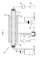
- FIG. 1 is a schematic view showing the cross-section of a helium gas separator material of the present invention.
- FIG. 2 is a schematic plan view of a gas separation portion of FIG. 1 seen from above.
- FIG. 3 is a schematic view showing a counter diffusion CVD apparatus.
- FIG. 4 is a schematic perspective view showing a composite substrate (including a porous ⁇ -alumina material) having not yet been used for the production of a helium gas separator material in examples.
- FIG. 5 is a graph showing the distribution of pore diameters of a porous ⁇ -alumina portion formed on the surface of the composite substrate (porous ⁇ -alumina material) in Example 1.
- FIG. 6 is a TEM image showing the cross-section of a helium gas separator material obtained in Example 1.
- FIG. 7 is a graph showing the analysis results of a Si/Al ratio in the depth direction from the surface of a gas separation portion of the helium gas separator material obtained in Example 1.
- FIG. 8 is a schematic view showing an evaluation apparatus using a gas chromatograph method at constant pressure.
- FIG. 9 is a graph showing a relationship established between a peak area of methane gas and helium gas in gas chromatography and a pressure at the time of gas separation when the volume variation method at constant pressure is applied to the helium gas separator material obtained in Example 1.
- a helium gas separator material of the present invention is constituted with a base portion and a gas separation portion joined to each other.
- the gas separation portion has a porous ⁇ -alumina portion containing a Ni element (hereinafter, simply referred to as a “porous ⁇ -alumina portion” in some cases) and a silica membrane portion.
- the base portion is composed of a porous ⁇ -alumina material having communication holes with an average diameter of 50 nm to 1,000 nm.
- the silica membrane portion is disposed on the inner wall of the communication holes in the porous ⁇ -alumina portion.
- the gas separation portion has pores which are surrounded and formed by the silica membrane portion and have an average diameter of 0.27 nm to 0.60 nm.
- the communication holes of the base portion are connected to the pores in the gas separation portion, and thus the helium gas separator material exhibits gas permeability from the base portion to the gas separation portion.
- helium gas separator material of the present invention When the helium gas separator material of the present invention is used in a high-pressure condition in a range of a gauge pressure exceeding 0.1 MPa and equal to or less than 12 MPa, helium gas is obtained at a high recovery ratio from mixed gas containing helium gas.
- the average diameter (0.27 nm to 0.60 nm) of the pores (fine pores) surrounded and formed by the silica membrane portion is greater than that of helium molecules in some areas, under the aforementioned pressure condition, helium gas preferentially permeates the pores before the gas having a molecular diameter greater than that of helium, such as carbon dioxide gas or nitrogen gas.
- such properties are suitably utilized for the use of separating helium gas as a limited resource or crude helium gas (mixed gas containing helium gas as a main component and other small-diameter gases) from natural gas containing hydrocarbon gases useful as fuel gas and helium gas, and then returning the helium gas or the crude helium gas into the ground or recovering it while preventing the gases from being naturally released into the atmosphere.
- crude helium gas mixtureed gas containing helium gas as a main component and other small-diameter gases
- FIG. 1 shows a schematic cross-sectional view of a helium gas separator material 10 of the present invention. That is, the helium gas separator material 10 of FIG. 1 includes a base portion 11 and a gas separation portion 12 .
- the base portion 11 is composed of a porous ⁇ -alumina material.
- the gas separation portion 12 has a porous ⁇ -alumina portion 13 containing a Ni element and a silica membrane portion 14 disposed on the inner wall of a communication hole in the porous portion. Furthermore, a pore (fine pore) 15 surrounded and formed by the silica membrane portion 14 is involved in the separation of helium gas.
- the pore (fine pore) 15 is formed in a manner in which the silica membrane portion 14 formed on the inner wall of the communication hole of the porous ⁇ -alumina portion 13 narrows the inner diameter (pore diameter) of the communication hole of the porous ⁇ -alumina portion 13 .
- the base portion 11 constituting the helium gas separator material 10 of the present invention is composed of a porous ⁇ -alumina material, and has a pore that penetrates the base portion from one side to the other side in the form of line or network. That is, the base portion 11 has a communication hole.
- the structure, shape, size, and the like of the base portion 11 are not particularly limited.
- the communication hole may be either a single through hole or a plurality of through holes that are regularly or irregularly continuous.
- the average diameter of the communication holes is 50 nm to 1,000 nm, preferably 60 nm to 180 nm, and more preferably 80 nm to 150 nm.
- the average diameter refers to a 50% permeation flux diameter in a pore distribution measured by means of a bubble point method and a half dry method by using a commercially available pore size distribution analyzer.
- the shape of the base portion 11 is selected according to the purpose, use, and the like.
- the base portion 11 can have a lump-like shape (a polyhedron, a sphere, or the like), a plate-like shape (a flat plate, a curved plate, or the like), a cylindrical shape (a round cylinder, a square cylinder, or the like), a semi-cylindrical shape, a rod-like shape, and the like.
- the size of the base portion 11 can be selected according to the purpose, use, and the like. Particularly, when it comes to separation of mixed gas, the thickness thereof is preferably equal to or greater than 150 ⁇ m.
- the shape and size of the helium gas separator material 10 of the present invention is generally the same as the shape and size of the base portion 11 .
- the gas separation portion 12 is joined to the base portion 11 . As shown in FIG. 2 , the gas separation portion 12 has the porous ⁇ -alumina portion 13 containing a Ni element, the silica membrane portion 14 , and the pore (fine pore) 15 .
- the porous ⁇ -alumina portion 13 is preferably composed of a porous material in a mixed anionic state in which Ni is dissolved in the form of solid solution in the crystal structure of ⁇ -Al 2 O 3 with a low degree of crystallinity.
- the fact that the porous material is composed of a solid solution of oxides can be confirmed by the peak shift and change in a lattice constant resulting from X-ray diffraction (XRD).
- a ratio between an Al element and a Ni element in the solid solution of oxides that is expressed in terms of Al 2 O 3 and NiO as oxides of Al and Ni is preferably 60 mol % to 99 mol %:1 mol % to 40 mol % (Al 2 O 3 :NiO), more preferably 80 mol % to 99 mol %:1 mol % to 20 mol % (Al 2 O 3 :NiO), and even more preferably 88 mol % to 98 mol %:2 mol % to 12 mol % (Al 2 O 3 :NiO), with respect to a total of 100 mol % of the oxides.
- the silica membrane portion 14 is preferably composed of amorphous silica.
- the silica membrane portion 14 may be formed all over the inner wall surface of the pore of the porous ⁇ -alumina portion 13 or may be formed on a portion of the inner wall surface of the pore.
- “formed in a portion” means that when seen in the cross-sectional view like FIG. 1 , the silica membrane portions 14 are formed and positioned at the same depth in the depth direction (cross-sectional direction) of the gas separation portion 12 .
- the “formed in a portion” may mean that the dimension of silica membrane portion 14 is smaller than the dimension of the gas separation portion 12 in the depth direction of the gas separation portion 12 .
- the length of the silica membrane portion 14 in the depth direction (cross-sectional direction) is preferably 50 nm to 500 nm, and more preferably 50 nm to 300 nm.
- the silica membrane portion 14 is preferably formed at an exposed surface side of the gas separation portion 12 in the inner wall of the communication hole of the porous ⁇ -alumina portion 13 (see FIG. 1 ).
- the silica membrane portions 14 may be constituted of the same material, and may form a continuous phase together with the membrane disposed on the exposed surface of the gas separation portion 12 (not shown in the drawing).
- the exposed surface of the gas separation portion 12 is a surface that comes into contact with mixed gas. When the mixed gas comes into contact with the exposed surface of the gas separation portion 12 , helium gas contained in the mixed gas permeates the gas separation portion 12 and the base portion 11 , and as a result, it is separated from the mixed gas.
- the average diameter of the pores (fine pores) 15 surrounded and formed by the silica membrane portion 14 is 0.27 nm to 0.60 nm, preferably 0.27 nm to 0.50 nm, and more preferably 0.27 nm to 0.38 nm.
- the thickness of the gas separation portion 12 is substantially the same as the thickness of the porous ⁇ -alumina portion 13 and is selected according to the purpose, use, and the like.
- the thickness is preferably 1.0 ⁇ m to 6.0 ⁇ m, and more preferably 2.0 ⁇ m to 4.0 ⁇ m.
- the method for producing the helium gas separator material of the present invention includes a coating film forming step of forming a coating film by using a composition, which contains an Al component-containing sol and a Ni compound, on the surface of the porous ⁇ -alumina material, a thermal treatment step of heating the coating film so as to form a porous ⁇ -alumina membrane containing a Ni element and obtain a complex in which the porous ⁇ -alumina membrane is joined to the surface of the porous ⁇ -alumina material, and a silica membrane portion forming step of supplying oxygen element-containing gas from the side of the porous ⁇ -alumina material to the side of the porous ⁇ -alumina membrane through the communication holes in the complex in a state where silica precursor gas is present near the surface of the porous ⁇ -alumina membrane in the complex and heating the complex, in this order.
- a coating film is formed by using a composition (hereinafter, referred to as a “sol composition”) containing an Al component-containing sol and a Ni compound.
- the sol composition may further contain a high-molecular-weight component, water, and the like so as to improve dispersibility, viscosity, and the like.
- a ratio between the Al component and the Ni component contained in the sol composition that is expressed in terms of Al 2 O 3 and NiO as oxides of the Al component and the Ni component is preferably 60 mol % to 99 mol %:1 mol % to 40 mol % (Al 2 O 3 :NiO), more preferably 80 mol % to 99 mol %:1 mol % to 20 mol % (Al 2 O 3 :NiO), and even more preferably 88 mol % to 98 mol %:2 mol % to 12 mol % (Al 2 O 3 :NiO), with respect to a total of 100 mol % of the oxides.
- the solid content concentration of the sol composition is preferably 5% by mass to 7% by mass, and the pH thereof is preferably 0.5 to 3.5.
- the sol composition is generally prepared by mixing the Al component-containing sol, the Ni compound, and the like together such that the concentration of each of the components becomes as described above.
- Al component-containing sol a known alumina sol (sol containing an alumina hydrate in the form of colloid particles) is used, and a boehmite sol is preferably used.
- the boehmite sol is a sol containing a substance represented by molecular formula AlO(OH).
- a sol obtained by the following method can be used. That is, first, an aluminum alkoxide such as aluminum isopropoxide, aluminum butoxide, or aluminum tri-sec butoxide is dissolved in a water-soluble organic solvent (isopropanol, ethanol, 2-butanol, 2-methoxyethanol, 2-ethoxyethanol, or the like). Thereafter, the solution is made acidic by using a monovalent acid such as hydrochloric acid, nitric acid, or perchloric acid, and hydrolyzed by being added to hot water at a temperature equal to or higher than 80° C., preferably hot water at 80° C. to 95° C. while being stirred. Generally, the stirring is continued for 1 hour to 20 hours at the aforementioned temperature.
- a monovalent acid such as hydrochloric acid, nitric acid, or perchloric acid
- a carboxylic acid anhydride such as acetic anhydride or maleic anhydride
- an acetoacetic ester such as methyl acetoacetate, ethyl acetoacetate, or propyl acetoacetate
- a dicarboxylic acid ester such as dimethyl malonate, diethyl malonate, or dipropyl malonate; or the like may be premixed with the aluminum alkoxide.
- Ni compound any of hydroxides, sulfates, nitrates, and the like containing Ni atoms can be used.
- examples of the high-molecular-weight component include a polyvinyl alcohol and modified products thereof, polyvinyl pyrrolidone, polyethylene glycol, polyethylene oxide, an acrylic acid ester copolymer, ammonium polyacrylate, sodium polyacrylate, carboxymethyl cellulose, methyl cellulose, hydroxypropyl methylcellulose, hydroxyethyl cellulose, hydroxypropyl cellulose, carboxymethyl hydroxyethylcellulose, starch and modified products thereof, and the like.
- the boehmite sol obtained by the aforementioned method and/or a commercially available boehmite sol may be mixed with a Ni compound.
- the compound exhibiting acidity when being dissolved in water is used, if the respective components described above are mixed together, the mixture becomes acidic.
- a composition containing a boehmite sol and a Ni component can be obtained.
- the high-molecular-weight component may be mixed thereinto.
- Each of the Ni compounds may be used in the form of a solid.
- either or both of the Ni compounds may be used in the form of a solution by being dissolved in water, an organic solvent, or the like.
- an acid or the like is used such that the pH of the sol composition to be prepared falls within the aforementioned preferable range.
- the high-molecular weight component when it is mixed thereinto, it may be used alone or used in the form of a solution such that the content thereof falls within a preferable range.
- the amount of the high-molecular-weight component is preferably 8% by mass to 18% by mass with respect to the total amount of the solid content of the Al component and the Ni component having not yet been mixed together.
- the sol composition is coated onto the surface of the porous ⁇ -alumina material and forms a coating film along the surface.
- the coating method include dip coating, spray coating, spin coating, and the like.
- the temperature of the sol composition at the time of coating of the sol composition is preferably 10° C. to 35° C., and more preferably 15° C. to 25° C.
- the temperature of the porous ⁇ -alumina material is preferably 10° C. to 35° C., and more preferably 15° C. to 25° C.
- the thickness of the coating film is selected according to the use, and generally is 1 ⁇ m to 6 ⁇ m.
- the sol composition may enter the pores in some cases because it is coated onto the porous ⁇ -alumina material. Accordingly, it is preferable to form the coating film by coating while preventing the sol composition from entering the pores.
- a solid solution of oxides generated by the following thermal treatment step blocks the communication holes of the porous ⁇ -alumina material in some cases.
- a porous ⁇ -alumina membrane containing a Ni element is formed by heating the coating film, whereby a complex in which the porous ⁇ -alumina membrane is joined to the surface of the porous ⁇ -alumina material is obtained.
- the coating film is thermally treated in the atmosphere or in an oxygen gas atmosphere under atmospheric pressure at a heating temperature which is preferably 450° C. to 950° C., more preferably 550° C. to 900° C., and even more preferably 600° C. to 850° C.
- the thermal treatment may be performed at a constant temperature or performed by varying temperature, as long as the temperature is within the above range.
- the heating temperature is too high, the phase transition from ⁇ -Al 2 O 3 to ⁇ -Al 2 O 3 may occur in some cases.
- the composition is stabilized, and a porous membrane composed of a uniform solid solution of oxides can be obtained. If the temperature is too low, the pore structure tends to become thermally unstable. In contrast, if the temperature is too high, the pore diameter tends to become large.
- the heating time, the temperature increase rate, and the like are appropriately selected according to the shape, size, and the like of the porous ⁇ -alumina material. However, the heating time is generally 0.5 hours to 10 hours.
- the coating film is slowly cooled such that the surface thereof does not crack.
- Each of the coating film forming step and the thermal treatment step may be performed once to form a single-layered porous ⁇ -alumina membrane. Alternatively, each of the steps can be repeated to form a laminate-type porous ⁇ -alumina membrane.
- the coating film By forming the coating film by using the sol composition and performing the thermal treatment under the aforementioned conditions, it is possible to efficiently form a porous membrane having pores with an average pore diameter equal to or less than 10 nm, preferably 1 nm to 8 nm, more preferably 1 nm to 7 nm, and even more preferably 1 nm to 6 nm. Because the pores of the porous ⁇ -alumina membrane are connected to the pores of the porous ⁇ -alumina material, the communication holes are formed in the cross-sectional direction of the complex.
- oxygen element-containing gas is supplied from the side of the porous ⁇ -alumina material to the side of the porous ⁇ -alumina membrane through the communication holes in the complex in a state where silica precursor gas is present near the surface of the porous ⁇ -alumina membrane in the complex, and the complex is heated, whereby a silica membrane portion is formed.
- the silica membrane portion forming step is preferably performed in a sealed space.
- this step when the complex is heated, in the communication holes of the porous ⁇ -alumina membrane that comes into contact with two kinds of gases, the gases react with each other, whereby a uniform silica membrane portion is formed on the inner wall of the communication holes of the porous ⁇ -alumina membrane.
- a tetraalkoxysilane gas such as tetramethoxysilane or tetraethoxysilane; or a siloxane compound gas such as tetraethyl siloxane, hexamethyl disiloxane, or tetramethyl cyclotetrasiloxane is preferably used.
- oxygen element-containing gas examples include oxygen gas, ozone gas, and the like.
- the silica precursor gas may be caused to stay near the surface of the porous ⁇ -alumina membrane in the complex.
- the silica precursor gas may be caused to continuously or intermittently flow such that a certain amount of the gas is present near the surface.
- the oxygen element-containing gas may be continuously or intermittently supplied to the side of the porous ⁇ -alumina membrane from the side of the porous ⁇ -alumina material.
- the volume ratio between the gases is preferably 20% by volume to 80% by volume:20% by volume to 80% by volume, and more preferably 30% by volume to 70% by volume:30% by volume to 70% by volume, since silica can be smoothly formed by bringing the gases into contact with each other inside the pores of ⁇ -alumina.
- the position of the silica membrane portion formed inside the porous ⁇ -alumina membrane and the formability of the silica membrane generally depend on the balance between the flow rate of the silica precursor gas and the flow rate of the oxygen element-containing gas.
- the oxygen element-containing gas passes through the communication holes of the complex and flows to the side of the porous ⁇ -alumina membrane.
- the silica membrane portion is generally positioned on the inner wall of the communication holes of the porous ⁇ -alumina material, and formed at the side of the exposed surface of the porous membrane.
- the heating temperature of the complex in the silica membrane portion forming step is preferably 200° C. to 700° C., and more preferably 500° C. to 600° C.
- a counter diffusion CVD apparatus shown in FIG. 3 can be used for performing the silica membrane portion forming step. A detailed constitution of the counter diffusion CVD apparatus will be described later.
- the helium gas separator material of the present invention separates helium gas from mixed gas consisting of helium gas and other gases (gases having a molecular diameter larger than that of helium), under conditions of a gauge pressure exceeding 0.1 MPa and equal to or less than 12 MPa and preferably 0.9 MPa to 12 MPa and a high temperature of 150° C. to 300° C. Accordingly, the recovery rate of helium gas can be improved.
- the flow rate of the mixed gas is appropriately selected according to the size and the like of the helium gas separator material. For instance, the flow rate of the mixed gas can be set to 40 cc/min to 500 cc/min or the like per a membrane area of 4.7 ⁇ 10 ⁇ 4 m 2 .
- a method for preparing a boehmite-based mixed solution used for forming a porous ⁇ -alumina portion containing a Ni element will be described.
- boehmite-based sol 24 ml of the boehmite-based sol was mixed with 16 ml of a 3.5% aqueous polyvinyl alcohol solution, thereby preparing a boehmite-based mixed solution (sol composition).
- a porous tubular material (inner diameter of 2.1 mm, outer diameter of 2.9 mm, and a length of 400 mm), which was composed of ⁇ -alumina and had network-like pores (average pore diameter of 150 nm) making the inner wall communicate with the outer wall, was used.
- the surface of portions 22 at both ends excluding the portion 21 was completely covered in advance with glass composed of Si—Ca—O.
- the substrate of FIG. 4 will be referred to as a “first composite substrate 20 ”.
- the boehmite-based mixed solution (sol composition) was coated onto the outer surface of the first composite substrate 20 and dried for 1 hour.
- the solution was prevented from entering the pores of the central portion 21 of the porous tubular material.
- the resultant was thermally treated for 1 hour at 800° C. in the atmosphere, thereby forming a porous membrane, which was composed of ⁇ -alumina and an oxide in the form of a solid solution containing Ni, on the whole surface of the first composite substrate 20 (surface of the central portion 21 and the portions 22 of both ends of the porous tubular material).
- a second composite structure including a porous composite portion having a porous membrane (porous ⁇ -alumina portion including a Ni element) that covered the outer surface of the central portion 21 of the porous tubular material.
- the thickness of the porous membrane (porous ⁇ -alumina portion containing a Ni element) formed on the outer surface of the central portion 21 by a cross-sectional SEM method was confirmed to be 3.0 ⁇ m.
- the pore diameter distribution of the porous membrane (porous ⁇ -alumina portion containing a Ni element) in the porous composite portion was measured by using a pore size distribution analyzer “Nano-Perm Porometer” manufactured by SEIKA CORPORATION. As a result, it was confirmed that the pore diameter ranged from 0.3 nm to 7.7 nm, and a 50% permeation flux diameter was about 5.9 nm (see FIG. 5 ).
- TMOS gas tetramethoxysilane gas
- oxygen gas oxygen element-containing gas
- a counter diffusion CVD apparatus 30 of FIG. 3 includes a reactor 31 , an electric furnace 32 , a rotary pump 33 , a bubbler for TMOS 34 , a mass flow controller (MFC) 35 , a cold trap 36 , a nitrogen gas cylinder 37 , an oxygen gas cylinder 38 , and the like.
- the pipe through which raw material gas passes is made of stainless steel, and a ribbon heater is coiled around the pipe so as to prevent condensation of the raw material gas in the pipe. Furthermore, before the apparatus is operated, both ends of the second composite structure were fixed by O-rings.
- the internal pressure of the reactor 31 was reduced. Then by using the electric furnace 32 , the internal temperature of the reactor 31 was increased to 600° C., and the oxygen gas and the TMOS gas were respectively supplied to the inside and outside (inside of the reactor 31 ) of the composite structure. All of the gases were supplied in an amount of 200 cc/min.
- the TMOS heated to 45° C. was gasified by means of nitrogen gas bubbling. Subsequently, the pipe of the TMOS was heated to 70° C. This operation was performed for 2 hours. As a result, a silica membrane portion was formed, and the porous composite portion was taken as a helium gas separator material (see FIG. 6 ).
- the gas permeability of the helium gas separator material was evaluated by a volume variation method at constant pressure (pressurization method) by using a gas permeability measurement apparatus shown in FIG. 8 .
- a measurement gas 43 methane gas containing 0.6% by volume of helium gas, that is, mixed gas composed of 99.4% by volume of methane gas and 0.6% by volume of helium gas was used.
- the measurement gas 43 (mixed gas or the like) for separation was supplied at a high pressure; separation was performed in a gas separation chamber 41 by using the helium gas separator material 10 ; and then the separated gas was discharged at atmospheric pressure.
- a pressure regulator valve 46 was controlled in order to set a pressure difference to 0.1 MPa, 0.5 MPa, or 0.9 MPa.
- the measurement gas 43 was introduced into the gas separation chamber 41 , the mixed gas (measurement gas 43 ) underwent separation by the helium gas separator material 10 , and the composition of the separated gas (permeation gas and non-permeation gas) was analyzed by a gas chromatography apparatus 48 .
- the flow rate of the measurement gas 43 introduced into the gas separation chamber 41 was set to 405 cc/min, 81 cc/min, or 40.5 cc/min (expressed in terms of methane) while being monitoring by a soap film flowmeter 47 .
- the flow rate of the separated gas introduced into a detector of the gas chromatography apparatus 48 was set to 20 cc/min. Although the non-permeation gas not treated by the helium gas separator material 10 could be introduced into the detector of the gas chromatography apparatus 48 at a sufficient flow rate, the flow rate of the permeation gas was less than 20 cc/min. Accordingly, at the time of gas separation, argon gas was supplied as a sweep gas 44 at a flow rate of 100 cc/min, such that the amount of the permeation gas introduced into the detector of the gas chromatography apparatus 48 became sufficient.
- a sign 45 indicates a mass flow controller; a sign 49 indicates the non-permeation gas; and a sign 50 indicates the permeation gas.
- the temperature was set to 50° C., 100° C., 150° C., or 200° C.; the pressure difference was set to 0.1 MPa, 0.5 MPa, or 0.9 MPa; and the flow rate of the measurement gas used was set to 405 cc/min. At this time, the helium gas concentration of a non-permeation side was analyzed. The results are shown in Table 1.
- the temperature was set to 50° C., 100° C., or 200° C.; the pressure difference was set to 0.9 MPa; and the flow rate of the measurement gas used was set to 405 cc/min, 81 cc/min, or 40.5 cc/min.
- the helium gas concentration of the non-permeation side and the helium gas concentration at the permeation side were analyzed. The results are shown in Table 2.
- the temperature was set to 200° C.; the pressure difference was set to 0.1 MPa, 0.5 MPa, or 0.9 MPa; and the flow rate of the measurement gas used was set to 405 cc/min, 81 cc/min, or 40.5 cc/min.
- the helium gas concentration of the non-permeation side and the helium gas concentration at the permeation side were analyzed. The results are shown in Table 3.
- FIG. 9 shows the relationship between each peak area and the pressure difference in gas chromatography.
- a white circle indicates the peak area of the helium gas
- a black circle indicates the peak area of the methane gas.
- the helium gas separator material of the present invention is used for separating helium gas and other gases from mixed gas containing helium gas under a high-pressure condition in a range of a gauge pressure exceeding 0.1 MPa and equal to or less than 12 MPa, the helium gas is obtained at a high recovery rate. Accordingly, the helium gas separator material of the present invention is particularly suited for separating gas at a high pressure.
- helium gas preferentially permeates the pores before the gas having a molecular diameter greater than that of helium, such as carbon dioxide gas or nitrogen gas.
- such properties are suitably utilized to separate helium gas as a limited resource or crude helium gas (mixed gas containing helium gas as a main component and other small-diameter gases) from natural gas containing hydrocarbon gases useful as fuel gas and helium gas, and then return the helium gas or the crude helium gas into the ground or recovering it while preventing the gases from being naturally released into the atmosphere.
- crude helium gas mixed gas containing helium gas as a main component and other small-diameter gases
Landscapes
- Chemical & Material Sciences (AREA)
- Engineering & Computer Science (AREA)
- Ceramic Engineering (AREA)
- Organic Chemistry (AREA)
- Inorganic Chemistry (AREA)
- Chemical Kinetics & Catalysis (AREA)
- Structural Engineering (AREA)
- Materials Engineering (AREA)
- Manufacturing & Machinery (AREA)
- Analytical Chemistry (AREA)
- General Chemical & Material Sciences (AREA)
- Oil, Petroleum & Natural Gas (AREA)
- Composite Materials (AREA)
- Separation Using Semi-Permeable Membranes (AREA)
- Porous Artificial Stone Or Porous Ceramic Products (AREA)
Applications Claiming Priority (3)
| Application Number | Priority Date | Filing Date | Title |
|---|---|---|---|
| JP2012-149846 | 2012-07-03 | ||
| JP2012149846 | 2012-07-03 | ||
| PCT/JP2013/067672 WO2014007140A1 (ja) | 2012-07-03 | 2013-06-27 | ヘリウムガス分離材及びその製造方法 |
Publications (2)
| Publication Number | Publication Date |
|---|---|
| US20150151242A1 US20150151242A1 (en) | 2015-06-04 |
| US9486734B2 true US9486734B2 (en) | 2016-11-08 |
Family
ID=49881897
Family Applications (1)
| Application Number | Title | Priority Date | Filing Date |
|---|---|---|---|
| US14/410,921 Active US9486734B2 (en) | 2012-07-03 | 2013-06-27 | Helium gas separator material and method for producing the same |
Country Status (8)
| Country | Link |
|---|---|
| US (1) | US9486734B2 (zh) |
| EP (1) | EP2870994A4 (zh) |
| JP (1) | JP6118800B2 (zh) |
| CN (1) | CN104394969B (zh) |
| AU (1) | AU2013284661B2 (zh) |
| CA (1) | CA2877621C (zh) |
| EA (1) | EA031252B1 (zh) |
| WO (1) | WO2014007140A1 (zh) |
Families Citing this family (10)
| Publication number | Priority date | Publication date | Assignee | Title |
|---|---|---|---|---|
| CN106102886A (zh) * | 2014-03-18 | 2016-11-09 | 东洋橡胶工业株式会社 | 含有酸性气体的气体的处理用分离膜、及含有酸性气体的气体处理用分离膜的制造方法 |
| CN107074427B (zh) * | 2014-11-05 | 2020-02-14 | 日本碍子株式会社 | 包装体、亚纳米膜结构体的保管或输送方法及亚纳米膜结构体 |
| JP6442277B2 (ja) * | 2014-12-26 | 2018-12-19 | 一般財団法人ファインセラミックスセンター | ガス分離膜、ガス分離材、及びガス分離膜の製造方法 |
| JP6702884B2 (ja) * | 2014-12-26 | 2020-06-03 | 日本碍子株式会社 | ガス分離方法 |
| WO2017086293A1 (ja) * | 2015-11-16 | 2017-05-26 | 株式会社ルネッサンス・エナジー・リサーチ | ガス回収装置、ガス回収方法、及び、半導体洗浄システム |
| US10480084B1 (en) * | 2016-03-03 | 2019-11-19 | Marathon Systems, Inc. | Modular cooling chamber for manifold of gaseous electrolysis apparatus with helium permeable element therefor |
| US11894158B2 (en) * | 2020-07-30 | 2024-02-06 | Lockheed Martin Corporation | Diffusion window for radioactive heat source |
| US20230264152A1 (en) * | 2020-08-03 | 2023-08-24 | Toray Industries, Inc. | Gas separation membrane, gas separation membrane module, and production method for gas separation membrane |
| CN112573494B (zh) * | 2020-12-23 | 2022-06-21 | 西南石油大学 | 一种利用水合物法的氦精制装置 |
| WO2023162854A1 (ja) * | 2022-02-28 | 2023-08-31 | 日本碍子株式会社 | ゼオライト膜複合体、ゼオライト膜複合体の製造方法および分離方法 |
Citations (16)
| Publication number | Priority date | Publication date | Assignee | Title |
|---|---|---|---|---|
| US5632803A (en) * | 1994-10-21 | 1997-05-27 | Nitrotec Corporation | Enhanced helium recovery |
| US5782959A (en) | 1995-06-23 | 1998-07-21 | Korea Advanced Institute Of Science And Technology | Process for preparing a composite inorganic membrane for hydrogen separation |
| JP2002253919A (ja) | 2001-02-27 | 2002-09-10 | Kyocera Corp | ガス分離フィルタ |
| US20020142172A1 (en) * | 1999-06-25 | 2002-10-03 | Brinker C. Jeffrey | Inorganic dual-layer microporous supported membranes |
| JP2003053167A (ja) | 2001-08-10 | 2003-02-25 | National Institute Of Advanced Industrial & Technology | 気体分離膜 |
| US20030222015A1 (en) * | 2002-06-04 | 2003-12-04 | Conoco Inc. | Hydrogen-selective silica-based membrane |
| US20040038044A1 (en) * | 2000-06-09 | 2004-02-26 | Victor Ruldolph | Silica membranes and process of production thereof |
| JP2005074317A (ja) | 2003-09-01 | 2005-03-24 | Daiso Co Ltd | 気体分離膜 |
| US7179325B2 (en) * | 2004-02-10 | 2007-02-20 | Virginia Tech Intellectual Properties, Inc. | Hydrogen-selective silica-based membrane |
| JP2007137752A (ja) | 2005-11-22 | 2007-06-07 | Japan Fine Ceramics Center | ヘリウム分離材及びその製造方法 |
| JP2007216106A (ja) | 2006-02-14 | 2007-08-30 | Hitachi Zosen Corp | ガス分離用のセラミック膜の製造方法 |
| CA2650680A1 (en) | 2006-04-28 | 2007-11-08 | Sho Sugiyama | Gas separation membrane |
| US20080134895A1 (en) * | 2006-12-08 | 2008-06-12 | General Electric Company | Gas Separator Apparatus |
| JP2010005602A (ja) | 2008-06-30 | 2010-01-14 | Japan Fine Ceramics Center | 耐水蒸気性多孔質膜、耐水蒸気性多孔質複合体及びこれらの製造方法 |
| US20110197762A1 (en) * | 2008-10-02 | 2011-08-18 | Basf Se | Template-Free Clathrasils And Clathrasil Membranes |
| US20130112078A1 (en) * | 2010-07-02 | 2013-05-09 | Ngk Insulators, Ltd. | Silica film filter and process for producing silica film filter |
-
2013
- 2013-06-27 EP EP13812948.1A patent/EP2870994A4/en not_active Withdrawn
- 2013-06-27 AU AU2013284661A patent/AU2013284661B2/en active Active
- 2013-06-27 JP JP2014523701A patent/JP6118800B2/ja active Active
- 2013-06-27 CA CA2877621A patent/CA2877621C/en active Active
- 2013-06-27 EA EA201590126A patent/EA031252B1/ru not_active IP Right Cessation
- 2013-06-27 CN CN201380033821.9A patent/CN104394969B/zh not_active Expired - Fee Related
- 2013-06-27 US US14/410,921 patent/US9486734B2/en active Active
- 2013-06-27 WO PCT/JP2013/067672 patent/WO2014007140A1/ja active Application Filing
Patent Citations (17)
| Publication number | Priority date | Publication date | Assignee | Title |
|---|---|---|---|---|
| US5632803A (en) * | 1994-10-21 | 1997-05-27 | Nitrotec Corporation | Enhanced helium recovery |
| US5782959A (en) | 1995-06-23 | 1998-07-21 | Korea Advanced Institute Of Science And Technology | Process for preparing a composite inorganic membrane for hydrogen separation |
| US20020142172A1 (en) * | 1999-06-25 | 2002-10-03 | Brinker C. Jeffrey | Inorganic dual-layer microporous supported membranes |
| US20040038044A1 (en) * | 2000-06-09 | 2004-02-26 | Victor Ruldolph | Silica membranes and process of production thereof |
| JP2002253919A (ja) | 2001-02-27 | 2002-09-10 | Kyocera Corp | ガス分離フィルタ |
| JP2003053167A (ja) | 2001-08-10 | 2003-02-25 | National Institute Of Advanced Industrial & Technology | 気体分離膜 |
| US20030222015A1 (en) * | 2002-06-04 | 2003-12-04 | Conoco Inc. | Hydrogen-selective silica-based membrane |
| JP2005074317A (ja) | 2003-09-01 | 2005-03-24 | Daiso Co Ltd | 気体分離膜 |
| US7179325B2 (en) * | 2004-02-10 | 2007-02-20 | Virginia Tech Intellectual Properties, Inc. | Hydrogen-selective silica-based membrane |
| JP2007137752A (ja) | 2005-11-22 | 2007-06-07 | Japan Fine Ceramics Center | ヘリウム分離材及びその製造方法 |
| JP2007216106A (ja) | 2006-02-14 | 2007-08-30 | Hitachi Zosen Corp | ガス分離用のセラミック膜の製造方法 |
| CA2650680A1 (en) | 2006-04-28 | 2007-11-08 | Sho Sugiyama | Gas separation membrane |
| CN101432061A (zh) | 2006-04-28 | 2009-05-13 | 旭化成化学株式会社 | 气体分离膜 |
| US20080134895A1 (en) * | 2006-12-08 | 2008-06-12 | General Electric Company | Gas Separator Apparatus |
| JP2010005602A (ja) | 2008-06-30 | 2010-01-14 | Japan Fine Ceramics Center | 耐水蒸気性多孔質膜、耐水蒸気性多孔質複合体及びこれらの製造方法 |
| US20110197762A1 (en) * | 2008-10-02 | 2011-08-18 | Basf Se | Template-Free Clathrasils And Clathrasil Membranes |
| US20130112078A1 (en) * | 2010-07-02 | 2013-05-09 | Ngk Insulators, Ltd. | Silica film filter and process for producing silica film filter |
Non-Patent Citations (9)
| Title |
|---|
| English language machine translation of JP 2007-216106, retrieved from http://translationportal.epo.org on Dec. 8, 2015. * |
| Int'l Search report issued on Aug. 20, 2013 in Int'l Application No. PCT/JP2013/067672. |
| Nagano, Takayuki et al., Hydrothermal stability of mesoporous Ni-doped y-A1203, Journal of the Ceramic Society of Japan, vol. 117, No. 7, p. 832-835 (2009). |
| Nagano, Takayuri et al., "Hydrothermal stability of mesoporous Ni-doped gamma-Al2O3", Journal of the Ceramic Society of Japan, 2009, vol. 117, No. 7, pp. 832-835. * |
| Nomura et al., "Preparation of a Catalyst Composite Silica Membrane Reactor for Steam Reforming Reaction by Using a Counterdiffusion CVD Method", Industrial & Engineering Chemistry Research, vol. 45, No. 11, pp. 3950-3954 (May 2006). |
| Office Action issued Mar. 29, 2016 in EP Application No. 13812948.1. |
| Search Report (with English translation) and Office Action issued Sep. 25, 2015 in CN Application No. 201380033821.9. |
| Tsuru et al., "A Bimodal Catalytic Membrane having a Hydrogen-Permselective Silica Layer on a Bimodal Catalytic Support:Preparation and Application to the Steam Reforming of Methane", Applied Catalysis A: General; vol. 302, No. 1, pp. 78-85 (Mar. 2006). |
| Tsuru et al., "Development of Metal-doped Silica Membranes for Increased Hydrothermal Stability and Their Applications to Membrane Reactors for Steam Reforming of Methane", Joural of Japan Petroleum Institute, vol. 54, No. 5, pp. 277-286 (Jan. 2011). |
Also Published As
| Publication number | Publication date |
|---|---|
| WO2014007140A1 (ja) | 2014-01-09 |
| CA2877621A1 (en) | 2014-01-09 |
| CN104394969B (zh) | 2017-03-15 |
| CN104394969A (zh) | 2015-03-04 |
| EA031252B1 (ru) | 2018-12-28 |
| CA2877621C (en) | 2021-06-15 |
| EA201590126A1 (ru) | 2015-05-29 |
| JP6118800B2 (ja) | 2017-04-19 |
| AU2013284661B2 (en) | 2018-03-08 |
| JPWO2014007140A1 (ja) | 2016-06-02 |
| EP2870994A4 (en) | 2016-04-27 |
| US20150151242A1 (en) | 2015-06-04 |
| EP2870994A1 (en) | 2015-05-13 |
| AU2013284661A1 (en) | 2015-02-05 |
Similar Documents
| Publication | Publication Date | Title |
|---|---|---|
| US9486734B2 (en) | Helium gas separator material and method for producing the same | |
| Gu et al. | Hydrothermally stable silica–alumina composite membranes for hydrogen separation | |
| Peters et al. | Hollow fibre microporous silica membranes for gas separation and pervaporation: synthesis, performance and stability | |
| Gu et al. | Ultrathin, hydrogen-selective silica membranes deposited on alumina-graded structures prepared from size-controlled boehmite sols | |
| Da Costa et al. | Novel molecular sieve silica (MSS) membranes: characterisation and permeation of single-step and two-step sol–gel membranes | |
| US7179325B2 (en) | Hydrogen-selective silica-based membrane | |
| Li et al. | Preparation of organic–inorganic hybrid silica membranes using organoalkoxysilanes: The effect of pendant groups | |
| US7938894B2 (en) | Hybrid organic-inorganic gas separation membranes | |
| Ahn et al. | Permeation properties of silica-zirconia composite membranes supported on porous alumina substrates | |
| Kanezashi et al. | Experimental and theoretical study on small gas permeation properties through amorphous silica membranes fabricated at different temperatures | |
| JP2008246299A (ja) | 水素ガス分離材製造方法 | |
| Jabbari et al. | Surface modification of α-alumina support in synthesis of silica membrane for hydrogen purification | |
| Ahn et al. | Synthesis and characterization of hydrogen selective silica membranes prepared by chemical vapor deposition of vinyltriethoxysilane | |
| US6943123B2 (en) | Silica membranes and process of production thereof | |
| KR20220094475A (ko) | 수소분리용 탄소분자체 분리막 및 암모니아 분해 반응을 이용한 수소 생산 방법 | |
| CN106102886A (zh) | 含有酸性气体的气体的处理用分离膜、及含有酸性气体的气体处理用分离膜的制造方法 | |
| Syauqiyah et al. | Interlayer-free silica-carbon template membranes from pectin and P123 for water desalination | |
| Kanezashi et al. | Pore size tuning of sol-gel-derived triethoxysilane (TRIES) membranes for gas separation | |
| Inoue et al. | Pore size tuning of bis (triethoxysilyl) propane (BTESP)-derived membrane for gas separation: Effects of the acid molar ratio in the sol and of the calcination temperature | |
| JP2007152230A (ja) | 緻密質シリカ系水素分離膜および水素製造方法 | |
| So et al. | Preparation of silica–alumina composite membranes for hydrogen separation by multi-step pore modifications | |
| JP4693267B2 (ja) | ガス分離フィルタ用無機多孔質体およびガス分離フィルタ並びにその製造方法 | |
| Nagano et al. | Degradation mechanism of an H 2-permselective amorphous silica membrane | |
| Gu et al. | Hybrid H2-selective silica membranes prepared by chemical vapor deposition | |
| Kanezashi et al. | Gas permeation properties of helium, hydrogen, and polar molecules through microporous silica membranes at high temperatures: correlation with silica network structure |
Legal Events
| Date | Code | Title | Description |
|---|---|---|---|
| AS | Assignment |
Owner name: JAPAN PETROLEUM EXPLORATION CO., LTD., JAPAN Free format text: ASSIGNMENT OF ASSIGNORS INTEREST;ASSIGNORS:NAGANO, TAKAYUKI;SATO, KOJI;CHIBA, KAZUMOTO;AND OTHERS;REEL/FRAME:035232/0631 Effective date: 20150125 Owner name: JAPAN FINE CERAMICS CENTER, JAPAN Free format text: ASSIGNMENT OF ASSIGNORS INTEREST;ASSIGNORS:NAGANO, TAKAYUKI;SATO, KOJI;CHIBA, KAZUMOTO;AND OTHERS;REEL/FRAME:035232/0631 Effective date: 20150125 |
|
| STCF | Information on status: patent grant |
Free format text: PATENTED CASE |
|
| MAFP | Maintenance fee payment |
Free format text: PAYMENT OF MAINTENANCE FEE, 4TH YEAR, LARGE ENTITY (ORIGINAL EVENT CODE: M1551); ENTITY STATUS OF PATENT OWNER: LARGE ENTITY Year of fee payment: 4 |
|
| MAFP | Maintenance fee payment |
Free format text: PAYMENT OF MAINTENANCE FEE, 8TH YEAR, LARGE ENTITY (ORIGINAL EVENT CODE: M1552); ENTITY STATUS OF PATENT OWNER: LARGE ENTITY Year of fee payment: 8 |