US9485399B2 - Billiard table lighting and game play monitor - Google Patents
Billiard table lighting and game play monitor Download PDFInfo
- Publication number
- US9485399B2 US9485399B2 US14/815,318 US201514815318A US9485399B2 US 9485399 B2 US9485399 B2 US 9485399B2 US 201514815318 A US201514815318 A US 201514815318A US 9485399 B2 US9485399 B2 US 9485399B2
- Authority
- US
- United States
- Prior art keywords
- billiard table
- table surface
- frame
- images
- camera
- Prior art date
- Legal status (The legal status is an assumption and is not a legal conclusion. Google has not performed a legal analysis and makes no representation as to the accuracy of the status listed.)
- Active
Links
Images


Classifications
-
- A—HUMAN NECESSITIES
- A63—SPORTS; GAMES; AMUSEMENTS
- A63D—BOWLING GAMES, e.g. SKITTLES, BOCCE OR BOWLS; INSTALLATIONS THEREFOR; BAGATELLE OR SIMILAR GAMES; BILLIARDS
- A63D15/00—Billiards, e.g. carom billiards or pocket billiards; Billiard tables
-
- H04N5/2256—
-
- F—MECHANICAL ENGINEERING; LIGHTING; HEATING; WEAPONS; BLASTING
- F21—LIGHTING
- F21S—NON-PORTABLE LIGHTING DEVICES; SYSTEMS THEREOF; VEHICLE LIGHTING DEVICES SPECIALLY ADAPTED FOR VEHICLE EXTERIORS
- F21S4/00—Lighting devices or systems using a string or strip of light sources
- F21S4/20—Lighting devices or systems using a string or strip of light sources with light sources held by or within elongate supports
- F21S4/28—Lighting devices or systems using a string or strip of light sources with light sources held by or within elongate supports rigid, e.g. LED bars
-
- F—MECHANICAL ENGINEERING; LIGHTING; HEATING; WEAPONS; BLASTING
- F21—LIGHTING
- F21S—NON-PORTABLE LIGHTING DEVICES; SYSTEMS THEREOF; VEHICLE LIGHTING DEVICES SPECIALLY ADAPTED FOR VEHICLE EXTERIORS
- F21S8/00—Lighting devices intended for fixed installation
- F21S8/04—Lighting devices intended for fixed installation intended only for mounting on a ceiling or the like overhead structures
- F21S8/046—Lighting devices intended for fixed installation intended only for mounting on a ceiling or the like overhead structures having multiple lighting devices, e.g. connected to a common ceiling base
-
- F—MECHANICAL ENGINEERING; LIGHTING; HEATING; WEAPONS; BLASTING
- F21—LIGHTING
- F21V—FUNCTIONAL FEATURES OR DETAILS OF LIGHTING DEVICES OR SYSTEMS THEREOF; STRUCTURAL COMBINATIONS OF LIGHTING DEVICES WITH OTHER ARTICLES, NOT OTHERWISE PROVIDED FOR
- F21V21/00—Supporting, suspending, or attaching arrangements for lighting devices; Hand grips
- F21V21/02—Wall, ceiling, or floor bases; Fixing pendants or arms to the bases
- F21V21/03—Ceiling bases, e.g. ceiling roses
-
- F—MECHANICAL ENGINEERING; LIGHTING; HEATING; WEAPONS; BLASTING
- F21—LIGHTING
- F21V—FUNCTIONAL FEATURES OR DETAILS OF LIGHTING DEVICES OR SYSTEMS THEREOF; STRUCTURAL COMBINATIONS OF LIGHTING DEVICES WITH OTHER ARTICLES, NOT OTHERWISE PROVIDED FOR
- F21V33/00—Structural combinations of lighting devices with other articles, not otherwise provided for
- F21V33/008—Leisure, hobby or sport articles, e.g. toys, games or first-aid kits; Hand tools; Toolboxes
-
- F—MECHANICAL ENGINEERING; LIGHTING; HEATING; WEAPONS; BLASTING
- F21—LIGHTING
- F21V—FUNCTIONAL FEATURES OR DETAILS OF LIGHTING DEVICES OR SYSTEMS THEREOF; STRUCTURAL COMBINATIONS OF LIGHTING DEVICES WITH OTHER ARTICLES, NOT OTHERWISE PROVIDED FOR
- F21V7/00—Reflectors for light sources
- F21V7/005—Reflectors for light sources with an elongated shape to cooperate with linear light sources
-
- H—ELECTRICITY
- H04—ELECTRIC COMMUNICATION TECHNIQUE
- H04N—PICTORIAL COMMUNICATION, e.g. TELEVISION
- H04N23/00—Cameras or camera modules comprising electronic image sensors; Control thereof
- H04N23/56—Cameras or camera modules comprising electronic image sensors; Control thereof provided with illuminating means
-
- H—ELECTRICITY
- H04—ELECTRIC COMMUNICATION TECHNIQUE
- H04N—PICTORIAL COMMUNICATION, e.g. TELEVISION
- H04N23/00—Cameras or camera modules comprising electronic image sensors; Control thereof
- H04N23/90—Arrangement of cameras or camera modules, e.g. multiple cameras in TV studios or sports stadiums
-
- H04N5/247—
-
- H—ELECTRICITY
- H04—ELECTRIC COMMUNICATION TECHNIQUE
- H04N—PICTORIAL COMMUNICATION, e.g. TELEVISION
- H04N5/00—Details of television systems
- H04N5/76—Television signal recording
- H04N5/765—Interface circuits between an apparatus for recording and another apparatus
- H04N5/77—Interface circuits between an apparatus for recording and another apparatus between a recording apparatus and a television camera
-
- H—ELECTRICITY
- H04—ELECTRIC COMMUNICATION TECHNIQUE
- H04N—PICTORIAL COMMUNICATION, e.g. TELEVISION
- H04N7/00—Television systems
- H04N7/18—Closed-circuit television [CCTV] systems, i.e. systems in which the video signal is not broadcast
- H04N7/181—Closed-circuit television [CCTV] systems, i.e. systems in which the video signal is not broadcast for receiving images from a plurality of remote sources
-
- H—ELECTRICITY
- H04—ELECTRIC COMMUNICATION TECHNIQUE
- H04N—PICTORIAL COMMUNICATION, e.g. TELEVISION
- H04N9/00—Details of colour television systems
- H04N9/79—Processing of colour television signals in connection with recording
- H04N9/80—Transformation of the television signal for recording, e.g. modulation, frequency changing; Inverse transformation for playback
- H04N9/82—Transformation of the television signal for recording, e.g. modulation, frequency changing; Inverse transformation for playback the individual colour picture signal components being recorded simultaneously only
- H04N9/8205—Transformation of the television signal for recording, e.g. modulation, frequency changing; Inverse transformation for playback the individual colour picture signal components being recorded simultaneously only involving the multiplexing of an additional signal and the colour video signal
- H04N9/8211—Transformation of the television signal for recording, e.g. modulation, frequency changing; Inverse transformation for playback the individual colour picture signal components being recorded simultaneously only involving the multiplexing of an additional signal and the colour video signal the additional signal being a sound signal
-
- H05B37/0227—
-
- H05B37/0236—
-
- H—ELECTRICITY
- H05—ELECTRIC TECHNIQUES NOT OTHERWISE PROVIDED FOR
- H05B—ELECTRIC HEATING; ELECTRIC LIGHT SOURCES NOT OTHERWISE PROVIDED FOR; CIRCUIT ARRANGEMENTS FOR ELECTRIC LIGHT SOURCES, IN GENERAL
- H05B45/00—Circuit arrangements for operating light-emitting diodes [LED]
-
- H—ELECTRICITY
- H05—ELECTRIC TECHNIQUES NOT OTHERWISE PROVIDED FOR
- H05B—ELECTRIC HEATING; ELECTRIC LIGHT SOURCES NOT OTHERWISE PROVIDED FOR; CIRCUIT ARRANGEMENTS FOR ELECTRIC LIGHT SOURCES, IN GENERAL
- H05B47/00—Circuit arrangements for operating light sources in general, i.e. where the type of light source is not relevant
- H05B47/10—Controlling the light source
- H05B47/105—Controlling the light source in response to determined parameters
- H05B47/115—Controlling the light source in response to determined parameters by determining the presence or movement of objects or living beings
- H05B47/12—Controlling the light source in response to determined parameters by determining the presence or movement of objects or living beings by detecting audible sound
-
- H—ELECTRICITY
- H05—ELECTRIC TECHNIQUES NOT OTHERWISE PROVIDED FOR
- H05B—ELECTRIC HEATING; ELECTRIC LIGHT SOURCES NOT OTHERWISE PROVIDED FOR; CIRCUIT ARRANGEMENTS FOR ELECTRIC LIGHT SOURCES, IN GENERAL
- H05B47/00—Circuit arrangements for operating light sources in general, i.e. where the type of light source is not relevant
- H05B47/10—Controlling the light source
- H05B47/105—Controlling the light source in response to determined parameters
- H05B47/115—Controlling the light source in response to determined parameters by determining the presence or movement of objects or living beings
- H05B47/125—Controlling the light source in response to determined parameters by determining the presence or movement of objects or living beings by using cameras
-
- F—MECHANICAL ENGINEERING; LIGHTING; HEATING; WEAPONS; BLASTING
- F21—LIGHTING
- F21Y—INDEXING SCHEME ASSOCIATED WITH SUBCLASSES F21K, F21L, F21S and F21V, RELATING TO THE FORM OR THE KIND OF THE LIGHT SOURCES OR OF THE COLOUR OF THE LIGHT EMITTED
- F21Y2103/00—Elongate light sources, e.g. fluorescent tubes
- F21Y2103/10—Elongate light sources, e.g. fluorescent tubes comprising a linear array of point-like light-generating elements
-
- F—MECHANICAL ENGINEERING; LIGHTING; HEATING; WEAPONS; BLASTING
- F21—LIGHTING
- F21Y—INDEXING SCHEME ASSOCIATED WITH SUBCLASSES F21K, F21L, F21S and F21V, RELATING TO THE FORM OR THE KIND OF THE LIGHT SOURCES OR OF THE COLOUR OF THE LIGHT EMITTED
- F21Y2115/00—Light-generating elements of semiconductor light sources
- F21Y2115/10—Light-emitting diodes [LED]
-
- Y—GENERAL TAGGING OF NEW TECHNOLOGICAL DEVELOPMENTS; GENERAL TAGGING OF CROSS-SECTIONAL TECHNOLOGIES SPANNING OVER SEVERAL SECTIONS OF THE IPC; TECHNICAL SUBJECTS COVERED BY FORMER USPC CROSS-REFERENCE ART COLLECTIONS [XRACs] AND DIGESTS
- Y02—TECHNOLOGIES OR APPLICATIONS FOR MITIGATION OR ADAPTATION AGAINST CLIMATE CHANGE
- Y02B—CLIMATE CHANGE MITIGATION TECHNOLOGIES RELATED TO BUILDINGS, e.g. HOUSING, HOUSE APPLIANCES OR RELATED END-USER APPLICATIONS
- Y02B20/00—Energy efficient lighting technologies, e.g. halogen lamps or gas discharge lamps
- Y02B20/40—Control techniques providing energy savings, e.g. smart controller or presence detection
Definitions
- This invention relates generally to billiard table lighting and more particularly to providing substantially uniform billiard table lighting to facilitate automated game play monitoring including image capture and automated image and video merging and other associated features.
- billiards and related table top games have been known for many years. Such games involve movement of balls on a table top. Typically a ball is struck with an instrument such as a cue to move the ball around the table top surface for positioning, to strike and move other balls, and the like. In some variants, balls are struck into holes in or at edges of the table top called pockets. In other variants, balls are struck so as to contact in a particular way other balls on the table top and/or cushions that line the table top to keep the balls on the table top surface.
- These games have a variety of names including cue sports, billiards, pool, snooker, pocket billiards, among others. For clarity and convenience, such games will be referred to collectively as billiards or billiard.
- the billiard table surface should be substantially uniformly lighted.
- the scene segmentation portion of the image analysis procedure is most efficiently accomplished by having a flat uniformly lit background.
- Billiard tables are typically lit using one or more light sources disposed above a center portion of the table such that lighting at the edges of the table is markedly worse than at the center.
- the World Pool-Billiard Association provides the following equipment specifications for lighting, such specifications do not suggest the level of uniform illumination typically needed for imaging projects: “15. Lights The bed and rails of the table must receive at least 520 lux (48 footcandles) of light at every point.
- a screen or reflector configuration is advised so that the center of the table does not receive noticeably more lighting than the rails and the corners of the table. If the light fixture above the table may be moved aside (referee), the minimum height of the fixture should be no lower than 40 inches (1.016 m) above the bed of the table. If the light fixture above the table is non-movable, the fixture should be no lower than 65 inches (1.65 m) above the bed of the table. The intensity of any directed light on the players at the table should not be blinding. Blinding light starts at 5000 lux (465 footcandles) direct view.
- the rest of the venue should receive at least 50 lux (5 footcandles) of light.” Under such specifications, uniform illumination sufficient for imaging analysis is not readily available. As a result, automatic image analysis of balls at table edges can result in inaccurate ball identification or insufficiently accurate ball location determinations. As a result, rapid automatic image analysis of ball movement and location cannot be accomplished efficiently and cost effectively with conventional billiard table lighting.
- a billiard table top lighting apparatus that provides substantially uniform lighting of a billiard table surface, but also optionally includes as an integrated component with multiple devices for recording and viewing game play embedded in the light structure itself.
- the lighting apparatus includes a frame supporting lights that are non-centrally placed such that no lights are supported above a middle portion of the billiard table surface. Other lighting configurations are possible.
- the frame can have an attractive profile and further include additional items above the billiard table surface to enable a variety of other features.
- the frame may support one or more cameras, one or more motion sensors, one or more microphones, and/or one or more computing devices to enable any of a variety of innovative features.
- Such features could include automatic game play recording from one or more perspectives by multiple cameras, automatically reconstructed, merged video track storage from the multiple camera views for replay, review, and analysis, automatic lighting and dimming control, control of the apparatus from any mobile device, and the like.
- FIG. 1 comprises a perspective view of an example lighting apparatus disposed above a billiard table as configured in accordance with various embodiments of the invention
- FIG. 2 comprises a top view of a billiard table to illustrate use of table markers to determine illumination measurement sites
- FIG. 3 comprises a top view of a billiard table to illustrate another use of table markers to determine illumination measurement sites
- FIG. 4 comprises a three-dimensional graph of illumination measurements on a billiard table lit using a prior art lighting apparatus
- FIG. 5 comprises a three-dimensional graph of illumination measurements on a billiard table lit using a lighting apparatus as configured in accordance with various embodiments of the invention
- FIG. 6 comprises a three-dimensional graph of a simulation of illumination measurements on a billiard table lit using a lighting apparatus as configured in accordance with various embodiments of the invention
- FIG. 7 comprises a top view of an example lighting apparatus as configured in accordance with various embodiments of the invention.
- FIG. 8 comprises a bottom view of the example lighting apparatus of FIG. 7 as configured in accordance with various embodiments of the invention.
- FIG. 9 comprises a plan view of a light source as used in accordance with various embodiments of the invention.
- FIG. 10 comprises a circuit diagram for the light sources of an example lighting apparatus as configured in accordance with various embodiments of the invention.
- FIG. 11 comprises a cross-section view of one example of a frame for an example lighting apparatus mounted above a billiard table in accordance with various embodiments of the invention
- FIG. 12 comprises a head end perspective view picture of an example lighting apparatus mounted above a billiard table in accordance with various embodiments of the invention
- FIG. 13A comprises an example image captured from a camera mounted above a middle portion of the billiard table surface in accordance with various embodiments of the invention
- FIG. 13B comprises an example image capture in sequence, after the image from FIG. 13A , from a camera mounted above a middle portion of the billiard table surface in accordance with various embodiments of the invention
- FIG. 14 comprises an example image captured from a camera mounted above the foot end portion of the billiard table surface in accordance with various embodiments of the invention
- FIG. 15 comprises a block diagram of an example lighting apparatus in communication with other devices in accordance with various embodiments of the invention.
- FIG. 16 comprises an example web page operator interface used to turn the lighting apparatus on or off and to control the light level in accordance with various embodiments of the invention
- FIG. 17A comprises an example composite image video frame constructed in real time from the camera mounted above the middle portion of the billiard table and the camera mounted at the head end of the billiard table in accordance with various embodiments of the invention
- FIG. 17B comprises an example composite image video frame, similar to FIG. 17A , constructed in real time from the camera mounted above the middle portion of the billiard table and the camera mounted at the foot end of the billiard table in accordance with various embodiments of the invention;
- FIG. 18A comprises an example of two threaded processes executed by the lighting apparatus to asynchronously capture video frames on one thread and to asynchronously perform image processing for a movement in the scene of the captured image on the other thread in accordance with various embodiments of the invention
- FIG. 18B comprises an example of four additional threaded processes, similar to those of FIG. 18A , executed by the lighting apparatus to asynchronously capture video frames from two additional cameras on two additional threads and to asynchronously perform image processing for a movement in the scene of the captured images on the other two additional threads in accordance with various embodiments of the invention;
- FIG. 18C comprises an example of two threaded processes executed by the lighting apparatus to asynchronously select individual frames of video from three cameras on one thread, to create a composite single output video stream for display, and to record the created output video with corresponding audio on the other thread in accordance with various embodiments of the invention;
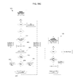
- FIG. 19 comprises a flow chart of an example method of execution for a lighting apparatus for merging video streams from multiple sources in accordance with various embodiments of the invention.
- the lighting apparatus 100 includes a frame 120 configured to support one or more lights 130 at a spaced distance Z above the billiard table surface 110 .
- the one or more lights 130 include a light source or sources mounted in the frame 120 in a configuration to provide substantially uniform illumination of the billiard table surface 110 .
- any lighting arrangement for providing uniform illumination can be applied, such as using in any combination strategically placed lights, lensing, reflectors, shades, diffusers, and the like.
- FIG. 2 illustrates how the table markers labeled 1 , 2 , and 3 at the foot end 210 and 1 through 7 at the table side 220 were used to establish measurement points 230 on the table surface where projections 240 from the table markers intersected.
- An Extech foot-candle/lux light meter was placed at each of the measurement points on a standard billiard table illuminated by a typical overhead, centered billiard table light manufactured by Diamond Billiards with no other ambient light sources on.
- the illumination measurements at the measurement points illustrated in FIG. 2 are listed in both foot-candles and lux in Table 1 below.
- Table 1 further notes the average illumination (AVG), the coefficient of variation of the measurements (CV) (which is a normalized measure of dispersion of a probability distribution or frequency distribution and is defined as the ratio of the standard deviation to the mean or average), and the standard deviation of the measurements (STD).
- AVG average illumination
- CV coefficient of variation of the measurements
- STD standard deviation of the measurements
- Table 2 lists illumination measurements taken at the same measurement points of a billiard table using a light configured in accord with the approaches of FIGS. 1 and 7-12 with no other ambient light sources on.
- FIG. 3 illustrates a similar approach to establishing illumination measurement points X except to expand the points X to include the intersection of the marker projections with the cushions 117 to determine the lighting uniformity for more of the billiard table surface 110 .
- the illumination for the table having the standard Diamond Billiards light was re-measured using these measurement points with results shown in Table 3 below and in FIG. 4 . Also, measurements were made on a number of other pool tables with other commonly used center table lights in two commercial pool establishments in the Chicago area with similar measurement results to those illustrated in Table 3 below.
- the billiard table lighted with the prototype light for which first measurements are listed above also had its illumination re-measured but with a dimmer set to adjust the average lighting output to closer to the commercially available Diamond Billiard light using the measurement points of FIG. 3 .
- the results are listed in Table 4 below and are illustrated in FIG. 5 .
- the arrangements described herein demonstrate substantially uniform illumination of the billiard table surface of between about 50 and 115 foot-candles.
- the disclosed lighting apparatus instead of a variance of 15% when using only mid-table readings or 28% when including illumination at the cushions, the disclosed lighting apparatus has a coefficient of variation of only 3% using the mid-table readings and only 7% when using illumination at the cushions.
- the cushion to cushion overall illumination uniformity for the disclosed lighting apparatus was better than the mid-table illumination uniformity for a standard billiard table light.
- substantially uniform illumination for the table will include an illumination coefficient of variation of about 14% or less, more preferably 10% or less, from cushion to cushion measured at the locations described above as shown in FIG. 3 .
- a frame 120 is mounted above the billiard table surface with one or more light sources 130 mounted in the frame 120 .
- the light source or sources may include light sources 130 mounted in the frame 120 in a configuration around a periphery of the billiard table surface 110 .
- the periphery will typically correspond to an area projected above the cushions or edges of the billiard table surface 110 .
- the frame 120 can be configured to mount the one or more lights 130 within a given horizontal distance from edges of the billiard table 110 such as within ten inches of the vertical projection of the cushion's 117 edge, and more preferably within five inches.
- the one or more lights are non-centrally placed such that no light sources are placed approximately directly above a middle portion of the billiard table surface 110 .
- the middle portion of the billiard table surface 110 will be generally understood to correspond to the area of the surface 110 between projections of the foot end 210 markers 2 and 4 of FIG. 3 from about marker 2 to about marker 8 of the side table 220 markers of FIG. 3 .
- the frame 120 is configured to mount pairs 710 of the one or more lights 130 in a generally perpendicular configuration above each corner of the billiard table surface 110 .
- the frame 120 is configured to mount two of the one or more lights 130 generally equally spaced along each long side of billiard table surface 110 as illustrated in FIG. 1 .
- the frame 120 may further include a middle frame portion 720 spanning across a middle portion 160 of the frame 120 corresponding to a middle portion of the billiard table surface 110 when mounted above the billiard table surface 110 .
- the light sources 130 can comprise any suitable light source.
- the light sources 130 each include a set of light emitting diode (LED) lights 930 mounted in a linear configuration such as illustrated in FIG. 9 .
- the light source 130 is an off the shelf light bar manufactured by PHILIPS having a mounting surface 940 on which the LED lights 930 are mounted, here in a linear configuration only, although additional LED lights could be mounted in addition to those set in a linear configuration.
- Mounting holes 950 in the mounting surface 940 facilitate mounting of the light source 130 to the frame 120 .
- Electrical connectors 960 allow for wired connections to a power source or driver or to another light source 130 such that one power source or driver can power and drive more than one light source 130 .
- FIG. 10 illustrates an example driver or power circuit for powering the light sources 130 of the lighting apparatus, in this example, a PHILIPS XITANIUM 75W 0.7-2.0 A 0-10V dimming device.
- the light sources 130 are divided into two groups with each group having its own otherwise identical circuit 1010 and 1012 .
- Each circuit in turn includes a power source 1020 , resistor 1030 , and rheostat 1040 connected in series with the light sources 130 .
- the rheostat 1040 controls the amount of current flowing through the LED light sources 130 thereby controlling the brightness of the lights as a group.
- a pulse width modulation (PWM) circuit may be used to modulate the light intensity.
- PWM pulse width modulation
- the frame 120 further supports shades, reflectors, or the like to direct light from the light sources 130 to the billiard table surface and protect the players' eyes from direct exposure to the LEDs.
- one or more reflectors and/or a diffuser element can be added to diffuse the light from the LEDs and provide a more uniform aesthetic.
- the frame 1120 is in the shape of a troffer, i.e., a narrow inverted trough, serving as a light source support, reflector, and holder of diffusers.
- the troffer frame 1120 is substantially hollow in its inner structure, which is configured to support one or more lights by a top portion or upper support construction 1124 of the inner structure opposing a portion of the troffer frame closest to the billiard table surface when installed. Opposing sides of the troffer frame 1120 extend down from the top portion encasing the lights and support reflective surfaces.
- the illustrated example is constructed from extruded aluminum and has continuous t-slots along the length of the top surface and inside surface to provide attachment points for supports to mount the frame to room ceilings, and for the attachment of video cameras 750 , or other devices.
- the t-slots accommodate a t-slot nut and screw/bolt 1122 which slides along the t-slot track to aid various attachments.
- the frame's upper support construction 1124 supports the lighting elements (here an LED circuit board 1140 supporting LEDs 1130 ) to face in the direction of the table surface.
- the LEDs 1130 are supported to face essentially straight down, in other words, such that the plane in which the LEDs 1130 are supports is essentially horizontal with the table surface although other arrangements are possible.
- Light from the LED's 1130 emits in a variety of directions and can be distractingly bright in one's field of view.
- the frame 1120 supports one or more diffusers.
- a particular diffuser arrangement is illustrated that redirects light rays from the LED 1130 that would otherwise be absorbed by the frame or be directed in a manner to not hit the table, so as to adequately light the billiard table surface and still diffuse light from the LEDs 1130 , and so as to not be distracting to a player.
- a first mirrored diffuser 1150 is disposed between the light source or sources (such as LED 1130 ) and an outer wall 1126 of the frame 1120 that faces away from the center of the billiard table surface.
- the back surface 1155 is mirrored and the rest of the thicker portion of the diffuser 1150 is constructed from a substance that diffuses the reflected light, both before and after reflection by the mirrored surface 1155 .
- the width of the diffuser 1150 is oriented essentially perpendicular with the billiard table surface so that the mirrored surface 1155 of the diffuser 1150 reflects light toward the center of the billiard table to help provide adequate lighting of the table surface.
- this diffuser 1150 is a commercially available diffuser (Evonik Platinum Ice OM001 X1) and is 0.34 inch thick.
- the mirrored diffusor is 1.8 inches from top to bottom in the cross section of FIG. 11 and, for a standard size 9 foot pocket billiard table, is 95.8 inches along the sides of the frame and is 45.8 inches along the ends of the frame. Other lengths are possible.
- a bottom diffuser 1160 is supported to be disposed between the light source or sources (such as LED 1130 ) and the billiard table surface.
- the bottom diffuser 1160 is a commercially available diffuser (Evonik Satin Ice OD002 DF) that is 0.08 inch thick and 2.125 inches wide. This diffuser 1160 diffuses the LED's 1130 light so that game players will not be distracted by the strong light that can emanate from individual LEDs. Instead, the observed light is diffused to provide a more uniform appearing light. This diffusing also spreads the light is a more uniform manner across the table surface.
- the bottom diffuser 1160 protects the LEDs 1130 from being struck by a cue.
- a second mirrored diffuser 1170 is disposed between the light source or sources (such as LED 1130 ) and an inner wall 1128 of the frame 1120 that faces toward the center of the billiard table surface.
- the inner wall 1128 may define a t-slot channel 1129 which optionally supports additional elements such as one or more cameras, motion sensors, or the lighting apparatus's middle section 160 .
- the second mirrored diffuser 1160 is a commercially available diffuser (Evonik Platinum Ice OM001 X1) that is 0.118 inch thick, 1.3 inches wide, and, for a standard size 9 foot pocket billiard table, is 95.8 inches along the sides of the frame and is 45.8 inches along the ends of the frame. Other lengths are possible.
- the second mirrored diffuser 1170 is disposed at an angle so that its mirrored surface 1175 reflects light generally toward both the bottom diffuser 1160 and the first mirrored diffuser 1150 to effect direction of more light at the billiard table surface through the bottom diffuser 1160 and via additional reflection off of the first mirrored diffuser 1140 .
- the diffusers 1150 , 1160 , and 1170 extend at least the length of the frame 1120 corresponding to a length of the frame along which the LED's 130 are supported although the diffusers 1150 , 1160 , and 1170 can extend any length along the frame.
- the bottom diffuser 1160 will extend around the entire frame 1120 to provide a more uniform aesthetic for the frame 1120 .
- FIG. 12 An example implementation of the frame 1120 as installed above a billiard table is illustrated in FIG. 12 , where the combined internal frame mirror and diffuser configuration smooth's out the light from the LEDs creating an aesthetic, even illumination on the table surface.
- the middle frame portion 720 may be configured to support a variety of other elements to add a variety of features to the lighting apparatus. For example, all or some of the electrical and/or computing elements needed to provide a variety of function can be mounted on the middle frame portion 720 top side to be not visible to the players.
- an A/C power strip 722 is mounted to the middle frame portion 720 to provide outlet power to various elements.
- An A/C switch 724 provides a master power switch for the lighting apparatus 100 .
- the middle portion 720 of the frame 120 supports a middle camera 730 directed to record images of the billiard table surface 110 .
- the camera 730 may be mounted so that the image sensor is in a plane essentially parallel to the table surface and high enough above the table such that the camera lens projects the entire table surface area onto its image sensor. If necessary, depending on the camera lens and image sensor size, and to keep the distance Z in FIG. 1 within a preferred height, the light path from the table to the camera may be deflected with a 45 degree mirror or similar optical arrangement, so that the image sensor is perpendicular to the table surface.
- the light path distance is made adjustable within the middle portion of the frame 720 , horizontally, so as not to alter the preferred height of the frame above the table, but to still obtain a mapping of the complete table surface area onto the image sensor.
- one frame of video from middle camera 730 maps the entire table surface onto the image sensor for rapid and efficient image processing purposes.
- the image processing of the table surface single frames is made even more efficient by the controlled uniform illumination provided by the lighting apparatus.
- FIGS. 13A-B show example images captured by the middle camera 730 .
- the lighting apparatus as further described herein may include a processing device 745 in operative communication to receive the images recorded by the middle camera 730 .
- a processor device can comprise a fixed-purpose hard-wired platform or can comprise a partially or wholly programmable platform. All of these architectural options are well known and understood in the art and require no further description here.
- the processing device 745 can also be configured to determine whether balls on the billiard table surface 110 are in motion or non-motion based on the images recorded by the middle camera 730 , such as by using image by image comparison techniques or by using object identification of billiard balls on a frame by frame comparison basis to track the ball motion between frames. Then, the processing device 745 can automatically control a setting for the lighting apparatus 100 based at least in part on the balls being either in motion or non-motion. For example, in response to determining non-motion of balls on the billiard table surface, the processing device 745 effects stopping recording or provision of images from the middle camera 730 .
- the processing device 745 and middle camera 730 can work together to operate efficiently because there is no reason to continue to transmit or record images of the billiard table surface 110 when image does not change, i.e., in between shots by the players.
- the processing device 745 effects provision of images from the middle camera 730 and from the end cameras 750 to reconstruct a real time or recorded video record from the combination of cameras as described herein.
- the processing device 745 is configured to detect particular images in the field of view of the middle camera 730 , in response to which, the processing device 745 can effect starting, stopping, or pausing recording or provision of images.
- a card having a particular image could be placed on the billiard table surface so as to be in the middle camera's 730 field of view or a particular hand gesture may be made over the table surface.
- the processing device 745 may react in particular corresponding ways. For example, in response to detecting one particular image (such as a large red dot on a card or other unique indicator), the processing device 745 can automatically stop execution of the program relating to the monitored game.
- the processing device 740 can automatically restart the program in response to detecting removal of the particular image.
- the processing device 745 may automatically start recording of a “new” game in response to detecting a particular image associated with that action such as a large green dot on a card.
- an end portion of the frame 120 corresponding to a head or foot end portion of the billiard table surface 110 when mounted above the billiard table surface 110 can support an end camera 750 directed to record images of at least a portion of the billiard table surface 110 and an area surrounding a head or foot end portion of the billiard table surface 110 opposite that over which the end camera 750 is mounted.
- FIG. 14 shows an example of an image captured by an end camera 750 .
- the frame 120 can support end cameras 750 at both the head and foot ends to capture images of both ends of the table.
- the end cameras 750 provide video images of player movement around the table and the player's approach to a shot. Such images can be useful for real time viewing, recording or transmission.
- the images can also be used to construct composite video frames together with the table view image frames obtained simultaneously by the middle camera 730 .
- Motion sensors 760 can be used to facilitate operation of the lighting apparatus.
- the processing device 740 can be in operative communication with the motion sensor 760 to automatically control a setting for the lighting apparatus in response to detection of motion.
- the processing device 740 may be configured to power off the plurality of lights 130 automatically in response to the motion sensor's 760 failing to detect motion for a threshold set time period by electronically communicating with an A/C switch circuit 724 .
- the processing device 740 may be configured to increase the lighting level by communicating with a pulse width modulation circuit 1040 , going from dimmed to a brightness sufficient to enable image capture and recording as described herein.
- the processing device 740 may be configured to provide images from a first camera in response to detecting motion from a first motion sensor and to provide images from a second camera in response to detecting motion from a second motion sensor. For instance, video or images will be recorded or transmitted from a camera oriented to capture images from an area from which motion is detected to ensure that the player movement is automatically recorded or transmitted.
- the processing device 745 may be configured to monitor sound captured by a microphone 770 to detect a strike sound having characteristics of a cue striking a billiard ball, and in response to detecting the strike sound, to automatically control a setting for the lighting apparatus 100 .
- the microphone 770 may be mounted to the frame 120 or be a part of another device (such as one of the video cameras) that is in communication with the processing device 745 .
- the processing device can be configured to, in response to detecting the strike sound, start recording or provision of images from the middle camera 730 mounted on the middle frame portion 720 of the frame 120 to automatically capture images of the moving balls.
- a processing device is configured to communicate with a user communication device, here the mobile device 1510 although other devices could be used, to provide images from the one or more cameras 730 and 750 disposed to capture images of the billiard table surface 110 and/or areas surrounding the billiard table surface 110 .
- the processing device may communicate directly with the user communication device.
- the processing device may then communicate with at least two cameras of the one or more cameras 730 and 750 to coordinate storage of the images or provision of the images to the user communication device 1510 .
- FIG. 15 One such example arrangement is illustrated in FIG. 15 , utilizing first and second processing devices 740 and 745 (Computer 1 and Computer 2 respectively in FIG. 15 ) where the first processing device 740 is operating the lighting apparatus to turn on, adjust the brightness, and start game play, and where the second processing device 745 is dedicated to communications with the cameras 730 and 750 to facilitate selection of the cameras from which individual video streams will be stored and/or provided to a user communication device 1510 .
- the second processing device 745 is in operative communication with the first processing device 740 via the wired connection 742 (such as an Ethernet or similar method) to receive commands with respect to starting and stopping the viewing or recording of images.
- the wired connection 742 such as an Ethernet or similar method
- a generally available router device 1520 can coordinate wireless communication such as through WiFi between the mobile device 1510 and the processing device 740 of the lighting apparatus 100 .
- the processing device 745 operates a server that hosts a web page operated from the mobile device 1510 .
- One example of the web page is shown in FIG. 16 .
- the server is assigned a local IP address by the router 1520 , and the IP address is displayed in the LCD panel 1560 .
- the mobile device 1510 interacts through the web page to control the light and allows the user to turn the light on or off by clicking the button 1720 .
- the web page interface also allows the user to adjust the light level by clicking on one of a series of bars 1730 in the interface.
- the web page of FIG. 16 allows control of the lamp on/off and intensity through a background program running on the processing device 1641 interfaced via the web page to either switch power on or off through the A/C switch 724 from the processing device 1641 to the lamp circuit, or in the case of adjusting the intensity, by controlling a pulse width modulation circuit interface to the lamp power supplies 1020 .
- the background program monitors the motion detectors 760 and adjusts the light intensity according to whether there is motion in the field of view of the motion detectors. As long as motion is present the lamp stays at the level set by the user. If there is no motion for a preset period, then the lamp automatically dims to a lower level using the pulse width modulation control. If there continues to be no motion for an additional preset period, the lamp turns off through the power on/off switch.
- the second processor 745 is operated by the display screen, keyboard, and mouse 1685 to run a software program to display in real time (e.g., 30 frames per second) an automatically generated composite video that combines the output from all three video cameras 730 and 750 .
- the composite video may optionally be recorded for later retrieval and review.
- the video is a recording, reproducing, or displaying of visual images made digitally of a scene captured sequentially in time, such that they can be viewed as moving visual images, even if there is no apparent motion for certain periods.
- the method of creating a video of billiard game play recorded simultaneously from multiple video cameras includes operating at least three independent image capture threads individually associated with separate cameras asynchronously in a same time interval.
- the independent image capture threads use shared memory resources and event done flags to communicate with each other.
- the independent image capture threads asynchronously capture individual image frames from the separate cameras. mage analysis of the captured individual image frames from the separate cameras to compare the individual image frames from a given camera of the separate cameras to determine which of the individual image frames are recording motion in the respective sequence of recordings from the respective ones of the separate cameras.
- Certain frames are chosen, displayed, and saved in a single video memory based on which of the separate cameras is recording motion.
- the method includes recording at specific time intervals, such as 30 frames per second, the chosen frames into a video file of the billiard game play.
- the chosen frames recorded into the video file comprise whatever is present at that instant in the single video memory.
- the video streams from the three cameras 730 and 750 are connected through USB ports to the second processing device 745 (labeled Computer 2 in FIG. 15 ).
- the video streams from the three video cameras are connected through USB ports to the processing device 745 , also labeled Computer 2 .
- the processing device 745 has an Intel quad-core CPU with hyper-threading, i.e., eight separate logical CPUs.
- the operating system for Computer 2 is an Ubuntu system.
- the eight logical CPUs can run simultaneously and asynchronously in a multi-threaded, multi-processor environment, such that a separate software thread can be running in each of the eight logical CPUs simultaneously.
- each video stream is input to a separate software module running on its own thread, sharing the memory allocations listed in Table 6.
- FIGS. 18A, 18B, and 18C eight flow diagrams are shown 1810 , 1820 , 1830 , 1840 , 1850 , 1860 , 1870 , and 1880 wherein each flow diagram represents a separate software thread.
- a main parent software process runs from the processing device 745 , which launches all of these threads asynchronously. However, they may share images and data through the use of shared memory resources allocated in the parent process. These shared resources are named and listed in TABLE 6 to enable clarity of presentation and understanding of the action of the different threads.
- CaptureThread 0 receives video input from the middle camera 730 in FIG. 7 .
- Each successive frame of video is available in that camera's internal hardware image buffer for 33.3 msec (at 30 frames/sec).
- the thread moves the image frame from CAM 0 internally into the processing device's 745 process allocated memory CFB 0 for that video stream.
- the thread sets its Frame Capture Flag CFLG 0 to 1 , which then allows the companion ProcessThread 0 to compute a difference metric DIF 0 between the current frame and the previous frame PFB 0 at 1822 .
- ProcessThread 0 then continues to copy the current image in CFB 0 to replace the image in the previous frame buffer PFB 0 at step 1824 and then sets its PFLG 0 to 1 , thus allowing the asynchronously running DirectorThread to use the DIF 0 value in FIG. 18C to update the AVGDIF.
- ImageCapture threads 1 and 2 1830 and 1850 are operating similarly to acquire image frames from their respective video cameras 750 in FIG. 7
- ProcessorThreads 1 and 2 1840 and 1860 are operating to compute the difference metrics DIF 1 and DIF 2 respectively between their current and previous image frames.
- six threads, operating on six separate logical CPUs are operating in this manner to achieve image frame input from the three video streams.
- the DirectorThread 1870 and the WriterThread 1880 are running to construct a composite video stream, combining the three separate video streams into one final composite stream.
- This composite video is displayed by the DirectorThread, and the DirectorThread 1870 determines which frames of video will be used to construct the composite video from the three inputs. If the record flag RFLG is set the composite video is also stored at 30 frames/sec, and an audio file is also recorded that is combined with the composite video stream at the end of the process.
- the SoX Sound Exchange program running on the Ubuntu operating system is used to merge the recorded .wav files with the recorded .avi files created by the WriterThread.
- the primary input, collected on a frame by frame basis, for the reconstructed composite video comes from camera 0 , which is the middle camera 730 in FIG. 7 , and which provides an overview of the table surface.
- camera 0 is the middle camera 730 in FIG. 7 , and which provides an overview of the table surface.
- One of the purposes of the composite video is to obtain an accurate record of ball positioning prior to each shot and during the movement of the balls afterwards. However, there are periods after the balls stop moving where other interesting and informational aspects of the play are occurring.
- the reconstructed composite video captures both of these activities through the utilization of the 3 cameras and reconstructing one composite video record. As long as motion is occurring, in the middle camera 730 view, the other two end table video streams from cameras 750 are not included in the reconstruction.
- the determination of motion in this example is determined by monitoring the difference DIF 0 between successive frames from camera 0 , and computed at 1822 in ProcessThread 0 1820 .
- the Director thread computes AVGDIF, a running average of the last 30 sequential DIF 0 values, and compares this value to a fixed threshold THRS to decide if motion is occurring.
- DFB is the memory buffer that displays the current image frame, and it will either be the current CFB 0 video frame without modification, or will later in the thread be overlaid in the corner with a PIP image.
- FIGS. 13A and 13B illustrate the type of frames that are included in the case of detected motion. These figures are from a sequence of a video frames showing the darker “4 ball” being hit by the white cue ball, propelling the “4” ball towards the side pocket. Because the ball motion from these and prior sequential frames results in an AVGDIF value above the threshold THRS, these frames would simply be added to the reconstructed composite video stream to the exclusion of the end camera views.
- the thread compares DIF 1 and DIF 2 at 1875 to see which end view has the most motion going on.
- the video stream having the most motion as reflected by the higher difference value DIF 1 or DIF 2 will be chosen to provide the end view frame to be reduced in size by 1 ⁇ 4 at step 1876 or 1877 and overlaid in a corner of DFB at step 1879 to create a picture-in-picture reconstructed image frame. If the difference value DIF 1 for video stream 1 is greater that the difference value DIF 2 for video stream 2 , the PIP frame is constructed 1870 from video frames from video streams 0 and 1 .
- the PIP frame is constructed 1876 from video frames from video streams 0 and 2 .
- the resulting video frames correspond to those illustrated in FIGS. 17A and 17B where the end view frame chosen is the one with the most motion.
- the operation of the DirectorThread is to determine if there is motion and choose the appropriate next sequential image frame for the displayed video. If there is no motion on the table, then the reconstructed video should show the activity around the periphery of the table, which is usually the player getting ready for the next shot.
- the PIP frame shows this, but still in the context of the overview of the balls on the table surface prior to motion stoppage.
- the WriterThread controls the synchronization of the process of recording the composite video record.
- the WriterThread is activated optionally by the operator of the apparatus and in that case the WriterThread is created and started by the DirectorThread. It also starts the audio recording during its initialization and starts a msec clock to measure the recorded frame time interval precisely. Because the audio signal is being recorded in real time, a composite video stream must be generated that corresponds exactly to the audio record with regard to its visual content.
- the three separate video camera streams can be started and operated asynchronously in CaptureThreads 0 , 1 and 2 , and their captured images can be subjected asynchronously to image processing in ProcessorThreads 0 , 1 , and 2 to compute a motion analysis metric. And then, the DirectorThread may further select asynchronously and if necessary add PIP frames for inclusion.
- the WriterThread without time variance must record the contents of the display buffer DFM at exactly 1/30 th of a second to acquire and construct the composite video. Whatever happens to be in the DFM display at that precise time is written to the recorded video output file.
- the determination of which end camera view to display can be made using information from motion sensors disposed on the frame to detect motion in areas around the table corresponding to the respective fields of view of the respective end cameras.
- one or more the processing devices can perform image analysis on the video feeds provided by the respective cameras to determine which camera is capturing the most motion.
- the determination of when to remove the overlaid video feed from an end camera can be made by detecting the sound of the cue striking a ball, image analysis of the video feed from the center camera, or a combination of both.
- the center camera may capture motion other than that of the balls on the table such as movement of a cue which can be confused with motion of the balls.
- Combining image analysis of the balls with sound detection of the striking cue allows the removal of the overlaid video frame in response to sound detection of the striking cue and maintaining removal of the overlaid video frame while detecting ball motion.
- the processing required to effect these actions can done on any combination of processing devices.
- the processing device is in communication with a middle camera 730 in FIG. 7 , to capture images of the table surface into video memory VM 2 , and cameras 750 at both ends of the frame to respectively capture images from opposite ends of the billiard table and first and second areas surrounding the respective ends of the table into video memories VM 1 or VM 3 respectively, and motion sensors 760 in FIG. 7 (labeled MS 1 and MS 2 in FIG. 19 ) disposed to detect motion in the areas surrounding the opposing ends of the table, and a microphone.
- the cameras and motion detectors could be mounted over and/or capturing images of or sensing motion around sides of the table in addition to or in lieu of the cameras over the ends of the table.
- the processing device wakes or resets with an initialization process 1910 . Then, assuming that there is no motion of the balls on the table, the processing device monitors for motion from the first area and the second area surrounding the billiard table surface through the use of one or more motion detectors or real time image analysis techniques described above. Then, the processing device determines at step 1920 with respect to detected motion from which camera images should be stored or displayed in video memory VM 4 (the output or display/recorded video memory).
- the processing device effects stopping storing or providing images from the second side/end camera into VM 4 , and effects storing or providing images 1933 from the first side/end camera to store or provide images from the first area into VM 4 .
- this includes storing or providing video or a video file that can be played on a display.
- the processing device effects stopping storing or providing images from the first side/end camera into VM 4 , and effects storing or providing images 1936 from the second side/end camera to store or provide images from the second area.
- the processing device next monitors for a ball hit; by detecting motion, for example, by real time image analysis, and/or by the striking of a ball, for example, by detecting a strike sound having characteristics of a cue striking a billiard ball.
- the processing device effects stopping storing or providing images from the respective side/end camera into VM 4 and effects storing or providing images VM 2 into VM 4 at step 1950 from the middle camera′ memory VM 2 so that images of the field of view capturing the table and the balls' motion are captured.
- the processing device then monitors 1960 for stoppage of the balls' motion, such as through use of one or more motion detectors or real time image analysis techniques described above.
- the processing device effects stopping storing or providing images from the middle camera and effects storing or providing images from the one of the side/end cameras as discussed above.
- the processing device may determine 1970 that the game is finished either by tracking which balls are on the table with respect to the game being played or by receiving a user initiated signal that indicates completion of play. In response to determining that the game is finished, the image capture and other game process is ended 1980 .
- each block may represent a module, segment, or portion of code that comprises program instructions to implement the specified logical function(s).
- the program instructions may be embodied in the form of source code that comprises human-readable statements written in a programming language or machine code that comprises numerical instructions recognizable by a suitable execution system such as a processor in a computer system or other system.
- the machine code may be converted from the source code, etc.
- each block may represent a circuit or a number of interconnected circuits to implement the specified logical function(s). Accordingly, a computer readable medium (being non-transitory or tangible) may store such instructions that are configured to cause a processing device to perform operations as described herein.
Landscapes
- Engineering & Computer Science (AREA)
- Multimedia (AREA)
- Signal Processing (AREA)
- General Engineering & Computer Science (AREA)
- Non-Portable Lighting Devices Or Systems Thereof (AREA)
- Studio Devices (AREA)
- Studio Circuits (AREA)
- Measurement Of The Respiration, Hearing Ability, Form, And Blood Characteristics Of Living Organisms (AREA)
Priority Applications (7)
| Application Number | Priority Date | Filing Date | Title |
|---|---|---|---|
| US14/815,318 US9485399B2 (en) | 2014-08-01 | 2015-07-31 | Billiard table lighting and game play monitor |
| US15/046,067 US9827483B2 (en) | 2014-08-01 | 2016-02-17 | Billiard table lighting and game play monitor |
| US15/336,062 US11045713B2 (en) | 2014-08-01 | 2016-10-27 | Billiard table lighting |
| US15/822,891 US10226685B2 (en) | 2014-08-01 | 2017-11-27 | Billiard table lighting and game play monitor |
| US17/362,264 US11654346B2 (en) | 2014-08-01 | 2021-06-29 | Billiard table lighting |
| US18/298,840 US12268952B2 (en) | 2014-08-01 | 2023-04-11 | Billiard table lighting |
| US19/070,314 US20250195986A1 (en) | 2014-08-01 | 2025-03-04 | Billiard Table Lighting |
Applications Claiming Priority (2)
| Application Number | Priority Date | Filing Date | Title |
|---|---|---|---|
| US201462032187P | 2014-08-01 | 2014-08-01 | |
| US14/815,318 US9485399B2 (en) | 2014-08-01 | 2015-07-31 | Billiard table lighting and game play monitor |
Related Child Applications (2)
| Application Number | Title | Priority Date | Filing Date |
|---|---|---|---|
| US15/046,067 Continuation-In-Part US9827483B2 (en) | 2014-08-01 | 2016-02-17 | Billiard table lighting and game play monitor |
| US15/336,062 Continuation US11045713B2 (en) | 2014-08-01 | 2016-10-27 | Billiard table lighting |
Publications (2)
| Publication Number | Publication Date |
|---|---|
| US20160037139A1 US20160037139A1 (en) | 2016-02-04 |
| US9485399B2 true US9485399B2 (en) | 2016-11-01 |
Family
ID=55181432
Family Applications (5)
| Application Number | Title | Priority Date | Filing Date |
|---|---|---|---|
| US14/815,318 Active US9485399B2 (en) | 2014-08-01 | 2015-07-31 | Billiard table lighting and game play monitor |
| US15/336,062 Active US11045713B2 (en) | 2014-08-01 | 2016-10-27 | Billiard table lighting |
| US17/362,264 Active US11654346B2 (en) | 2014-08-01 | 2021-06-29 | Billiard table lighting |
| US18/298,840 Active US12268952B2 (en) | 2014-08-01 | 2023-04-11 | Billiard table lighting |
| US19/070,314 Pending US20250195986A1 (en) | 2014-08-01 | 2025-03-04 | Billiard Table Lighting |
Family Applications After (4)
| Application Number | Title | Priority Date | Filing Date |
|---|---|---|---|
| US15/336,062 Active US11045713B2 (en) | 2014-08-01 | 2016-10-27 | Billiard table lighting |
| US17/362,264 Active US11654346B2 (en) | 2014-08-01 | 2021-06-29 | Billiard table lighting |
| US18/298,840 Active US12268952B2 (en) | 2014-08-01 | 2023-04-11 | Billiard table lighting |
| US19/070,314 Pending US20250195986A1 (en) | 2014-08-01 | 2025-03-04 | Billiard Table Lighting |
Country Status (5)
| Country | Link |
|---|---|
| US (5) | US9485399B2 (enExample) |
| EP (1) | EP3174612B1 (enExample) |
| JP (1) | JP6654633B2 (enExample) |
| CN (1) | CN107073328A (enExample) |
| WO (1) | WO2016019288A1 (enExample) |
Cited By (6)
| Publication number | Priority date | Publication date | Assignee | Title |
|---|---|---|---|---|
| US20160310829A1 (en) * | 2014-07-02 | 2016-10-27 | Bing QIAO | Projection type billiard ball hitting intelligent auxiliary system and method |
| US20160317904A1 (en) * | 2014-07-02 | 2016-11-03 | Bing QIAO | Projection type billiard system gesture/billiard-rod control system and implementation method thereof |
| US9827483B2 (en) | 2014-08-01 | 2017-11-28 | Smart Billiard Lighting LLC | Billiard table lighting and game play monitor |
| USD835652S1 (en) | 2015-12-10 | 2018-12-11 | Smart Billiard Lighting LLC | Display screen with transitional graphical user interface of a billiard game |
| US11045713B2 (en) | 2014-08-01 | 2021-06-29 | Smart Billiard Lighting LLC | Billiard table lighting |
| USD1046036S1 (en) * | 2021-12-17 | 2024-10-08 | Clawson Custom Cues, Inc. | Billiard table |
Families Citing this family (18)
| Publication number | Priority date | Publication date | Assignee | Title |
|---|---|---|---|---|
| JP6873730B2 (ja) * | 2016-02-17 | 2021-05-19 | スマート ビリヤード ライティング エルエルシー | ビリヤードテーブル照明及びゲームプレイモニタ |
| USD792002S1 (en) * | 2016-04-12 | 2017-07-11 | Lite Systems, Inc. | Pendant billiard luminaire |
| CN109691237A (zh) * | 2016-09-16 | 2019-04-26 | 昕诺飞控股有限公司 | 光照控制 |
| KR101840134B1 (ko) * | 2016-10-25 | 2018-03-19 | 박정길 | 조명 제어 기능을 구비한 당구 연습 시스템 |
| US11462121B2 (en) * | 2017-02-15 | 2022-10-04 | Cae Inc. | Visualizing sub-systems of a virtual simulated element in an interactive computer simulation system |
| CN107297069B (zh) * | 2017-07-21 | 2023-06-13 | 佛山科学技术学院 | 一种智能台球训练桌 |
| GB2567800A (en) * | 2017-08-29 | 2019-05-01 | Social Entertainment Ventures Ltd | Detecting ball strike position |
| CN108211319B (zh) * | 2018-01-30 | 2019-06-18 | 平顶山学院 | 用于体育田径的多功能智能记录台 |
| USD880755S1 (en) * | 2018-06-13 | 2020-04-07 | Lite Systems, Inc. | Pendant luminaire with louvers |
| USD930747S1 (en) * | 2019-02-20 | 2021-09-14 | Indian Industries, Inc. | Collapsible billiards table |
| EP3958992A4 (en) * | 2019-04-26 | 2023-05-03 | Starker, Thomas Charles | Broadcast-ready table sports system |
| CN112929792B (zh) * | 2021-01-21 | 2022-06-28 | 稿定(厦门)科技有限公司 | 基于Sox的音频处理方法、介质、设备及装置 |
| US12311253B2 (en) | 2022-08-31 | 2025-05-27 | Perceptive Lighting, Inc. | Billiard light |
| WO2023034458A1 (en) * | 2021-08-31 | 2023-03-09 | Perceptive Lighting, Inc | Billiard light |
| US11748406B2 (en) * | 2021-11-01 | 2023-09-05 | Lucasfilm Entertainment Company Ltd. LLC | AI-assisted sound effect editorial |
| EP4475970A4 (en) | 2022-02-09 | 2025-05-14 | Martin, Blake Robert | Interactive led system for enhancing billiard gameplay |
| GB2622618B (en) * | 2022-09-23 | 2025-01-01 | Gravity Brands Ltd | Dartboard camera unit |
| CN116870457A (zh) * | 2023-05-17 | 2023-10-13 | 东莞市起航灯饰科技有限公司 | 一种新型的台球桌氛围灯 |
Citations (61)
| Publication number | Priority date | Publication date | Assignee | Title |
|---|---|---|---|---|
| US4882676A (en) | 1988-09-09 | 1989-11-21 | Kop Andrew R Van De | Method and apparatus for rating billiard shots and displaying optimal paths |
| WO1990005005A1 (en) | 1988-11-10 | 1990-05-17 | Geoffrey Anthony Williams | Game arrangement |
| DE4039315A1 (de) | 1990-12-10 | 1992-06-11 | Nsm Ag | Lern- und spielvorrichtung fuer ball- und kugelspiele |
| US5272607A (en) | 1991-10-01 | 1993-12-21 | Thorn Licht Gmbh | Lighting fixture |
| FR2804879A1 (fr) | 2000-02-10 | 2001-08-17 | Thierry Lecoq | Billard interactif |
| JP2002186702A (ja) * | 2000-12-22 | 2002-07-02 | Sefamedeia Create:Kk | 撞球練習装置および撞球練習システム |
| US6554451B1 (en) | 1999-08-27 | 2003-04-29 | Lumileds Lighting U.S., Llc | Luminaire, optical element and method of illuminating an object |
| US20030081410A1 (en) | 2001-03-29 | 2003-05-01 | Bailey Bendrix L. | Continuation of lighting system |
| US6626558B2 (en) | 1997-02-28 | 2003-09-30 | Electro Optical Sciences Inc. | Apparatus for uniform illumination of an object |
| JP2006043017A (ja) | 2004-08-03 | 2006-02-16 | Seiko Epson Corp | 表示装置 |
| US20060063599A1 (en) | 2004-09-23 | 2006-03-23 | Michael Greenspan | Method and apparatus for positional error correction in a robotic pool systems using a cue-aligned local camera |
| US7284870B2 (en) | 2003-09-17 | 2007-10-23 | Moritex Corporation | Lighting apparatus and image pick-up apparatus with lighting |
| US20080111310A1 (en) | 2006-11-14 | 2008-05-15 | Lydia Parvanta | Game table television and projector system, and method for same |
| KR20090013980A (ko) | 2007-08-03 | 2009-02-06 | 포항공과대학교 산학협력단 | 화상 입출력을 통한 당구 게임 지원 장치 |
| US20090116210A1 (en) | 2007-03-30 | 2009-05-07 | Shaun Cutler | Device for intelligent illumination |
| KR20090074127A (ko) | 2009-06-05 | 2009-07-06 | 김대환 | 당구 게임용 코칭 시스템 |
| WO2009126982A2 (de) | 2008-04-17 | 2009-10-22 | Thomas Riml | Vorrichtung zum ausüben eines sports bzw. spiels an räumlich getrennten spielorten |
| JP2009273542A (ja) | 2008-05-13 | 2009-11-26 | Taito Corp | ビリヤード台の球移動管理装置 |
| US7648257B2 (en) | 2006-04-21 | 2010-01-19 | Cree, Inc. | Light emitting diode packages |
| CN101628174A (zh) | 2009-08-18 | 2010-01-20 | 刘铮 | 自动畸变校正的斯诺克台球桌面坐标的提取方法 |
| KR20100015258A (ko) | 2008-08-04 | 2010-02-12 | 신진석 | 당구점수 계산장치 |
| ES2333839A1 (es) | 2009-09-22 | 2010-03-01 | Cubensis, S.L. | Dispositivo entrenador personal de billar. |
| JP2010046446A (ja) | 2008-08-25 | 2010-03-04 | Sega Corp | 撮像手段を備えたゲーム装置 |
| US20100062859A1 (en) | 2008-09-10 | 2010-03-11 | Rice Patrick G | Method and system for tracking parlor game statistics |
| US20100225236A1 (en) | 2009-03-06 | 2010-09-09 | Micronic Laser Systems Ab | Statistical Illuminator |
| CN101848376A (zh) | 2010-05-19 | 2010-09-29 | 朱万政 | 台球走位分析电视系统 |
| US20110021256A1 (en) | 2009-07-27 | 2011-01-27 | Obscura Digital, Inc. | Automated enhancements for billiards and the like |
| US20110021257A1 (en) | 2009-07-27 | 2011-01-27 | Obscura Digital Inc. | Automated enhancements for billiards and the like |
| US7922346B2 (en) | 2007-03-16 | 2011-04-12 | J. Morita Manufacturing Corporation | Medical lighting apparatus and medical imaging apparatus |
| US7936119B2 (en) | 2008-10-16 | 2011-05-03 | Yung Pun Cheng | Wide-angle LED lighting lamp with high heat-dissipation efficiency and uniform illumination |
| KR20110075967A (ko) | 2009-12-29 | 2011-07-06 | 이기혁 | 당구장 시스템 |
| US7976187B2 (en) | 2008-03-27 | 2011-07-12 | Cree, Inc. | Uniform intensity LED lighting system |
| KR20110085735A (ko) | 2010-01-21 | 2011-07-27 | 조영복 | 당구경기용 영상제공장치 및 그 방법 |
| KR20110112683A (ko) | 2010-04-07 | 2011-10-13 | 장경일 | 터치스크린 모니터를 이용한 당구 게임 진행 시스템 및 방법 |
| US20110255276A1 (en) | 2010-04-19 | 2011-10-20 | Coward Mark T | Lighting assembly |
| GB2479902A (en) | 2010-04-28 | 2011-11-02 | Christopher Mark Southworth | Billiards apparatus for automatically tallying a player's score |
| US20110294585A1 (en) | 2008-12-16 | 2011-12-01 | Thomas David Penna | Arrangement adapted to be used with conventional billiard tables for greater utilisation, versatility and/or application of said tables |
| CN102327697A (zh) | 2011-10-14 | 2012-01-25 | 李姣昂 | 投影式台球训练系统及其实现方法 |
| US8105174B1 (en) | 2006-02-21 | 2012-01-31 | Schofield Paul E Sr | Computerized method and system for administering universal rating of pocket billiard players |
| US20120033426A1 (en) | 2009-04-16 | 2012-02-09 | Koninklijke Philips Electronics N.V. | Lighting system, space with a lighting system, and method of providing an illumination profile using such a lighting system |
| KR101145126B1 (ko) | 2011-08-19 | 2012-05-14 | 주식회사 비앤에스 | 당구게임 교육 시스템과 교육 제어방법 |
| US20120134155A1 (en) | 2009-08-05 | 2012-05-31 | Koninklijke Philips Electronics N.V. | Adjustable lighting unit with controllable orientation and intensity of light beam |
| KR20120069233A (ko) | 2010-12-20 | 2012-06-28 | 주식회사 웨이브애프터 | 당구자세 교정 시스템 및 교정 방법, 기록매체 |
| US8210723B2 (en) | 2007-06-29 | 2012-07-03 | Dialight Corporation | LED lens array optic with a highly uniform illumination pattern |
| US20120182733A1 (en) | 2011-01-13 | 2012-07-19 | Lg Electronics Inc. | Flat led lighting device |
| US20120188757A1 (en) | 2006-09-12 | 2012-07-26 | Cree, Inc. | Led lighting fixture |
| US8253353B2 (en) | 2007-07-16 | 2012-08-28 | Koninklijke Philips Electronics N.V. | Driving a light source |
| US8258721B2 (en) | 2008-09-16 | 2012-09-04 | Evolution Lighting, Llc | Remotely controllable track lighting system |
| KR20120113578A (ko) | 2011-04-05 | 2012-10-15 | 권택만 | 당구 가이드 장치 |
| US8292733B2 (en) | 2009-08-31 | 2012-10-23 | Disney Enterprises, Inc. | Entertainment system providing dynamically augmented game surfaces for interactive fun and learning |
| US20130033859A1 (en) | 2010-04-23 | 2013-02-07 | Koninklijke Philips Electronic, N.V. | Led-based lighting unit |
| US20130039050A1 (en) | 2011-08-08 | 2013-02-14 | Quarkstar, Llc | Solid-State Luminaire |
| US20130039061A1 (en) | 2010-04-16 | 2013-02-14 | Opto Design, Inc. | Light display method and light display device |
| KR20130057102A (ko) | 2011-11-23 | 2013-05-31 | (주)한일에스티엠 | 당구 시뮬레이터 |
| CN103170126A (zh) | 2011-12-20 | 2013-06-26 | 西安天动数字科技有限公司 | 互动台球桌系统 |
| CN103182177A (zh) | 2013-04-07 | 2013-07-03 | 张云 | 一种台球自动记分和辅助判罚系统 |
| KR20130087247A (ko) | 2012-01-27 | 2013-08-06 | (주) 토리랩 | 당구게임 동영상 분류 장치, 방법 및 이를 이용한 당구게임 동영상 서비스 시스템 |
| CN103285578A (zh) | 2013-06-28 | 2013-09-11 | 赵来玺 | 台球复位装置 |
| US8616971B2 (en) | 2009-07-27 | 2013-12-31 | Obscura Digital, Inc. | Automated enhancements for billiards and the like |
| US20140043801A1 (en) | 2008-11-19 | 2014-02-13 | Rohm Co., Ltd. | Led lamp |
| US8810687B2 (en) * | 2009-06-29 | 2014-08-19 | Canon Kabushiki Kaisha | Image capturing apparatus and control method thereof |
Family Cites Families (87)
| Publication number | Priority date | Publication date | Assignee | Title |
|---|---|---|---|---|
| GB190808509A (enExample) * | 1908-04-16 | 1909-02-25 | John Henry Faulkner | |
| GB191107344A (en) * | 1911-03-24 | 1912-01-04 | Herbert Mitchell | Improvements in and connected with Electric Lighting Arrangements for Billiard Tables, Shops and the like. |
| GB611673A (en) * | 1946-05-04 | 1948-11-02 | Vincent Hartley | An improved illuminating means for use with billiard tables and the like |
| US3743287A (en) | 1972-01-19 | 1973-07-03 | C Liermann | Combined frame and elevatable pool table assembly |
| US4751627A (en) | 1987-05-01 | 1988-06-14 | Usher Scott D | Tubular lighting system |
| US4827386A (en) | 1988-07-08 | 1989-05-02 | Kenall Manufacturing Co. | Water-proof and impact-resistant lighting fixture |
| USD372591S (en) | 1995-04-06 | 1996-08-13 | Simmons Juvenile Products Company, Inc. | Mirror |
| CH690312A5 (de) | 1995-10-12 | 2000-07-14 | Burri Ag | Leuchtkasten für Plakate. |
| USD396841S (en) | 1995-10-16 | 1998-08-11 | Taylor Gregory P | Motorboat gas tank cushion kit |
| JPH09213160A (ja) | 1996-02-02 | 1997-08-15 | Yazaki Corp | ロック機構 |
| USD420354S (en) | 1997-10-17 | 2000-02-08 | Domingo Morales | Light emitting strip for a pager |
| US5947583A (en) * | 1997-12-29 | 1999-09-07 | Castano; Guillermo | Illuminating cue stick rack |
| US6244970B1 (en) * | 1998-06-19 | 2001-06-12 | Diamond Billiard Products, Inc. | Optical sensors for cue ball detection |
| USD441479S1 (en) | 2000-01-14 | 2001-05-01 | Brunswick Bowling & Billiards Corporation | Billiard table light fixture |
| US6601976B1 (en) | 2000-04-07 | 2003-08-05 | Thin-Lite Corporation | Snap assembled light fixture apparatus |
| USD468855S1 (en) | 2001-04-04 | 2003-01-14 | Artemide S.P.A. | Table lamp |
| US6965567B2 (en) | 2001-04-09 | 2005-11-15 | Telefonaktiebolaget Lm Ericsson (Publ) | Method and apparatus for selecting a link set |
| USD487598S1 (en) | 2002-08-22 | 2004-03-16 | Lighting Innovation Center Ag | Lamp |
| US20040132535A1 (en) * | 2003-01-07 | 2004-07-08 | Sumko Michael H. | Laser billiard ball positioning apparatus |
| US20040254024A1 (en) | 2003-06-12 | 2004-12-16 | Marvin Thomas | Color coded pool table numbering system |
| US7697026B2 (en) | 2004-03-16 | 2010-04-13 | 3Vr Security, Inc. | Pipeline architecture for analyzing multiple video streams |
| CA2462620A1 (en) | 2004-03-30 | 2005-09-30 | Jvl Corporation | Pool video game |
| USD536468S1 (en) | 2004-05-13 | 2007-02-06 | Boyd Lighting Fixture Co. | Lighting fixture |
| USD512173S1 (en) | 2004-11-22 | 2005-11-29 | Lusa Lighting, Inc. | Lighting fixture |
| USD511852S1 (en) | 2004-11-22 | 2005-11-22 | Lusa Lighting, Inc. | Lighting fixture |
| USD525384S1 (en) | 2004-11-30 | 2006-07-18 | Genlyte Thomas Group Llc | Fluorescent luminaire |
| US7390111B2 (en) | 2005-03-04 | 2008-06-24 | Hubbell Incorporated | Mounting clip for lighting fixtures |
| JP2006306305A (ja) | 2005-04-28 | 2006-11-09 | T An T:Kk | 車両用室内灯 |
| US20070026956A1 (en) | 2005-07-29 | 2007-02-01 | Tournament Games, Inc. | One-player pool scoring system and method |
| USD564694S1 (en) | 2006-02-17 | 2008-03-18 | Liteco | Light fixture |
| CN2906295Y (zh) | 2006-04-29 | 2007-05-30 | 中山腾龙体育器材有限公司 | 桌球台用的吊灯 |
| JP2008129554A (ja) * | 2006-11-27 | 2008-06-05 | Sanyo Electric Co Ltd | 撮像装置及びオートフォーカス制御方法 |
| AU2009200364A1 (en) | 2008-02-04 | 2009-08-20 | Aristocrat Technologies Australia Pty Limited | A method of gaming, a gaming system, and a gaming apparatus |
| US7766536B2 (en) * | 2008-02-15 | 2010-08-03 | Lunera Lighting, Inc. | LED light fixture |
| EP2113501A1 (en) | 2008-04-25 | 2009-11-04 | Laboratorios Del. Dr. Esteve, S.A. | 5-Methyl-1-(naphthalen-2-YL)-1H-Pyrazoles useful as sigma receptor inhibitors |
| USD604871S1 (en) | 2008-09-15 | 2009-11-24 | Scott Denton | Lighting fixture |
| CN201282530Y (zh) | 2008-10-27 | 2009-07-29 | 刘铮 | 一种计算机台球辅助裁判装置 |
| USD602626S1 (en) | 2009-02-27 | 2009-10-20 | Koninklijke Philips Electronics N.V. | Suspended luminaire |
| USD653800S1 (en) | 2009-03-31 | 2012-02-07 | Grand General Accessories Manufacturing | Bezel for a vehicle |
| USD649974S1 (en) | 2009-07-17 | 2011-12-06 | Tencent Technology (Shenzhen) Company Limited | Display panel with a transitional computer icon |
| KR20110006697U (ko) * | 2009-12-28 | 2011-07-06 | 주식회사 코스모스산업 | 조명이 구비된 당구대 |
| USD643142S1 (en) | 2010-01-21 | 2011-08-09 | Ridi-Leuchten Gmbh | Pendant lamp |
| TWD143268S1 (zh) | 2010-02-26 | 2011-10-11 | 赫伯特渥德曼兩合股份有限公司 | 吊燈 |
| DE102010003393A1 (de) | 2010-03-29 | 2011-09-29 | Osram Gesellschaft mit beschränkter Haftung | Deckenpendelleuchte und Aufsatzstück für eine Deckenpendelleuchte |
| USD645193S1 (en) | 2010-04-30 | 2011-09-13 | Focal Point, L.L.C. | Lighting fixture |
| US9308435B1 (en) | 2010-05-07 | 2016-04-12 | Thomas Rohrmeister | Stylized billiard rack and a method of playing a moving billiard game using the stylized billard rack |
| CN201815088U (zh) | 2010-09-13 | 2011-05-04 | 刘铮 | 一种斯诺克台球互动装置 |
| USD689504S1 (en) | 2010-10-14 | 2013-09-10 | Aisin Seiki Kabushiki Kaisha | Display screen for a vehicle with graphical user interface |
| USD689062S1 (en) | 2010-10-14 | 2013-09-03 | Aisin Seiki Kabushiki Kaisha | Display screen for a vehicle with graphical user interface |
| USD654204S1 (en) | 2010-11-22 | 2012-02-14 | Ron Friesen | Pool table light fixture |
| JP2012187221A (ja) | 2011-03-09 | 2012-10-04 | Hiroyuki Hashimoto | ビリヤード装置を利用したコミュニケーションシステム |
| DE202011000598U1 (de) | 2011-03-16 | 2011-10-17 | U. K. Technology Corp. | Deckenleuchte |
| USD649679S1 (en) | 2011-04-08 | 2011-11-29 | GE Lighting Solutions, LLC | Rectangular luminaire |
| USD650509S1 (en) | 2011-04-08 | 2011-12-13 | GE Lighting Solutions, LLC | Rectangular floating light |
| US20120285060A1 (en) | 2011-05-12 | 2012-11-15 | Design Ideas, Ltd. | Picture frames |
| JP2014527255A (ja) | 2011-05-17 | 2014-10-09 | ピクシー・ライティング・エルエルシイ | フラットパネル照明システムおよび後付けキット |
| JP2013004312A (ja) | 2011-06-16 | 2013-01-07 | Panasonic Corp | 照明制御システム |
| USD676599S1 (en) | 2011-08-30 | 2013-02-19 | Honda Motor Co., Ltd. | Vehicle headlight washer cover |
| CN202270324U (zh) * | 2011-10-14 | 2012-06-13 | 李姣昂 | 投影式台球训练系统 |
| JP6013040B2 (ja) | 2012-06-26 | 2016-10-25 | 株式会社カネカ | 有機elモジュール |
| KR101329889B1 (ko) * | 2012-07-13 | 2013-11-15 | 주식회사 필립인텍스 | 엘이디가 장착된 써크라인 조명등 장치 |
| US9124856B2 (en) | 2012-08-31 | 2015-09-01 | Disney Enterprises, Inc. | Method and system for video event detection for contextual annotation and synchronization |
| US20140063776A1 (en) | 2012-09-04 | 2014-03-06 | Finelite Inc. | LED lighting system |
| CN203249110U (zh) | 2013-01-23 | 2013-10-23 | 余姚付世光电科技有限公司 | 一种led面板灯 |
| US20140308999A1 (en) | 2013-04-10 | 2014-10-16 | Arkady AIZENBERG | Method of playing a ricochet game |
| USD716489S1 (en) | 2013-04-22 | 2014-10-28 | Cooper Technologies Company | Edgelit suspended luminaire |
| CN203258508U (zh) | 2013-05-20 | 2013-10-30 | 杨伟 | 组合式桌球台灯 |
| CN103871078B (zh) * | 2013-07-12 | 2016-04-13 | 北京瑞盖科技有限公司 | 一种台球击球关键信息检测方法及系统 |
| KR20150024146A (ko) | 2013-08-26 | 2015-03-06 | 엘지전자 주식회사 | 엘이디 등 기구 모듈 |
| JP5884798B2 (ja) * | 2013-09-13 | 2016-03-15 | 株式会社情報技研 | ボール個別位置判別装置 |
| USD730563S1 (en) | 2013-12-24 | 2015-05-26 | Kaper Ii, Inc. | Ceiling or cabinet light |
| USD744689S1 (en) | 2014-06-03 | 2015-12-01 | Lighing Science Group Corporation | Troffer luminaire |
| CN104117203B (zh) * | 2014-07-02 | 2015-12-09 | 乔冰 | 红外投影式台球娱乐系统及其实现方法 |
| CN104117201B (zh) * | 2014-07-02 | 2015-12-09 | 乔冰 | 投影式台球系统手势/球杆控制系统及其实现方法 |
| USD780973S1 (en) | 2014-07-30 | 2017-03-07 | Orion Energy Systems, Inc. | Light fixture |
| JP6654633B2 (ja) | 2014-08-01 | 2020-02-26 | スマート ビリヤード ライティング エルエルシー | ビリヤードテーブル照明及びゲームプレイモニタ |
| US9827483B2 (en) | 2014-08-01 | 2017-11-28 | Smart Billiard Lighting LLC | Billiard table lighting and game play monitor |
| NL2013445B1 (nl) | 2014-09-09 | 2016-09-28 | Hak4T Facilities B V | Verlichtingsarmatuur voor het ondersteunen van natuurlijk licht, samenstel van verlichtingsarmaturen en werkwijze voor het bedrijven van een dergelijk verlichtingsarmatuur. |
| USD740480S1 (en) | 2014-11-03 | 2015-10-06 | Mahdi Thompson | Lighting fixture |
| KR101590489B1 (ko) | 2015-02-12 | 2016-02-01 | 송재운 | 엣지타입의 엘이디 매립형 등기구 |
| USD773098S1 (en) | 2015-09-28 | 2016-11-29 | Focal Point, Llc | Light fixture |
| USD802819S1 (en) | 2015-09-28 | 2017-11-14 | Focal Point, Llc | Light fixture |
| USD800368S1 (en) | 2015-09-29 | 2017-10-17 | Focal Point, Llc | Light fixture |
| USD835652S1 (en) | 2015-12-10 | 2018-12-11 | Smart Billiard Lighting LLC | Display screen with transitional graphical user interface of a billiard game |
| USD776328S1 (en) | 2015-12-10 | 2017-01-10 | Smart Billiard Lighting LLC | Light frame |
| JP6873730B2 (ja) | 2016-02-17 | 2021-05-19 | スマート ビリヤード ライティング エルエルシー | ビリヤードテーブル照明及びゲームプレイモニタ |
| JP7314539B2 (ja) | 2019-03-12 | 2023-07-26 | 株式会社デンソー | 車両用送風装置 |
-
2015
- 2015-07-31 JP JP2017526481A patent/JP6654633B2/ja active Active
- 2015-07-31 US US14/815,318 patent/US9485399B2/en active Active
- 2015-07-31 WO PCT/US2015/043198 patent/WO2016019288A1/en not_active Ceased
- 2015-07-31 EP EP15827424.1A patent/EP3174612B1/en active Active
- 2015-07-31 CN CN201580048360.1A patent/CN107073328A/zh active Pending
-
2016
- 2016-10-27 US US15/336,062 patent/US11045713B2/en active Active
-
2021
- 2021-06-29 US US17/362,264 patent/US11654346B2/en active Active
-
2023
- 2023-04-11 US US18/298,840 patent/US12268952B2/en active Active
-
2025
- 2025-03-04 US US19/070,314 patent/US20250195986A1/en active Pending
Patent Citations (64)
| Publication number | Priority date | Publication date | Assignee | Title |
|---|---|---|---|---|
| US4882676A (en) | 1988-09-09 | 1989-11-21 | Kop Andrew R Van De | Method and apparatus for rating billiard shots and displaying optimal paths |
| EP0435910A1 (en) | 1988-09-09 | 1991-07-10 | Nsm Ag | A SYSTEM FOR TRACKING BILLIARDS BALLS. |
| WO1990005005A1 (en) | 1988-11-10 | 1990-05-17 | Geoffrey Anthony Williams | Game arrangement |
| DE4039315A1 (de) | 1990-12-10 | 1992-06-11 | Nsm Ag | Lern- und spielvorrichtung fuer ball- und kugelspiele |
| US5272607A (en) | 1991-10-01 | 1993-12-21 | Thorn Licht Gmbh | Lighting fixture |
| US6626558B2 (en) | 1997-02-28 | 2003-09-30 | Electro Optical Sciences Inc. | Apparatus for uniform illumination of an object |
| US6554451B1 (en) | 1999-08-27 | 2003-04-29 | Lumileds Lighting U.S., Llc | Luminaire, optical element and method of illuminating an object |
| FR2804879A1 (fr) | 2000-02-10 | 2001-08-17 | Thierry Lecoq | Billard interactif |
| JP2002186702A (ja) * | 2000-12-22 | 2002-07-02 | Sefamedeia Create:Kk | 撞球練習装置および撞球練習システム |
| US20030081410A1 (en) | 2001-03-29 | 2003-05-01 | Bailey Bendrix L. | Continuation of lighting system |
| US7284870B2 (en) | 2003-09-17 | 2007-10-23 | Moritex Corporation | Lighting apparatus and image pick-up apparatus with lighting |
| JP2006043017A (ja) | 2004-08-03 | 2006-02-16 | Seiko Epson Corp | 表示装置 |
| US20060063599A1 (en) | 2004-09-23 | 2006-03-23 | Michael Greenspan | Method and apparatus for positional error correction in a robotic pool systems using a cue-aligned local camera |
| US20110070960A1 (en) | 2004-09-23 | 2011-03-24 | Michael Greenspan | Method and apparatus for positional error correction in a robotic pool system using a cue-aligned local camera |
| US8105174B1 (en) | 2006-02-21 | 2012-01-31 | Schofield Paul E Sr | Computerized method and system for administering universal rating of pocket billiard players |
| US7648257B2 (en) | 2006-04-21 | 2010-01-19 | Cree, Inc. | Light emitting diode packages |
| US20120188757A1 (en) | 2006-09-12 | 2012-07-26 | Cree, Inc. | Led lighting fixture |
| US20080111310A1 (en) | 2006-11-14 | 2008-05-15 | Lydia Parvanta | Game table television and projector system, and method for same |
| US7922346B2 (en) | 2007-03-16 | 2011-04-12 | J. Morita Manufacturing Corporation | Medical lighting apparatus and medical imaging apparatus |
| US20090116210A1 (en) | 2007-03-30 | 2009-05-07 | Shaun Cutler | Device for intelligent illumination |
| US8210723B2 (en) | 2007-06-29 | 2012-07-03 | Dialight Corporation | LED lens array optic with a highly uniform illumination pattern |
| US8253353B2 (en) | 2007-07-16 | 2012-08-28 | Koninklijke Philips Electronics N.V. | Driving a light source |
| KR20090013980A (ko) | 2007-08-03 | 2009-02-06 | 포항공과대학교 산학협력단 | 화상 입출력을 통한 당구 게임 지원 장치 |
| US7976187B2 (en) | 2008-03-27 | 2011-07-12 | Cree, Inc. | Uniform intensity LED lighting system |
| WO2009126982A2 (de) | 2008-04-17 | 2009-10-22 | Thomas Riml | Vorrichtung zum ausüben eines sports bzw. spiels an räumlich getrennten spielorten |
| JP2009273542A (ja) | 2008-05-13 | 2009-11-26 | Taito Corp | ビリヤード台の球移動管理装置 |
| KR20100015258A (ko) | 2008-08-04 | 2010-02-12 | 신진석 | 당구점수 계산장치 |
| JP2010046446A (ja) | 2008-08-25 | 2010-03-04 | Sega Corp | 撮像手段を備えたゲーム装置 |
| US20100062859A1 (en) | 2008-09-10 | 2010-03-11 | Rice Patrick G | Method and system for tracking parlor game statistics |
| US20130002166A1 (en) | 2008-09-16 | 2013-01-03 | Evolution Lighting, Llc | Remotely controllable track lighting system |
| US8258721B2 (en) | 2008-09-16 | 2012-09-04 | Evolution Lighting, Llc | Remotely controllable track lighting system |
| US7936119B2 (en) | 2008-10-16 | 2011-05-03 | Yung Pun Cheng | Wide-angle LED lighting lamp with high heat-dissipation efficiency and uniform illumination |
| US20140043801A1 (en) | 2008-11-19 | 2014-02-13 | Rohm Co., Ltd. | Led lamp |
| US20110294585A1 (en) | 2008-12-16 | 2011-12-01 | Thomas David Penna | Arrangement adapted to be used with conventional billiard tables for greater utilisation, versatility and/or application of said tables |
| US20100225236A1 (en) | 2009-03-06 | 2010-09-09 | Micronic Laser Systems Ab | Statistical Illuminator |
| US20120033426A1 (en) | 2009-04-16 | 2012-02-09 | Koninklijke Philips Electronics N.V. | Lighting system, space with a lighting system, and method of providing an illumination profile using such a lighting system |
| KR20090074127A (ko) | 2009-06-05 | 2009-07-06 | 김대환 | 당구 게임용 코칭 시스템 |
| US8810687B2 (en) * | 2009-06-29 | 2014-08-19 | Canon Kabushiki Kaisha | Image capturing apparatus and control method thereof |
| US20110021257A1 (en) | 2009-07-27 | 2011-01-27 | Obscura Digital Inc. | Automated enhancements for billiards and the like |
| US8616971B2 (en) | 2009-07-27 | 2013-12-31 | Obscura Digital, Inc. | Automated enhancements for billiards and the like |
| US20110021256A1 (en) | 2009-07-27 | 2011-01-27 | Obscura Digital, Inc. | Automated enhancements for billiards and the like |
| US20120134155A1 (en) | 2009-08-05 | 2012-05-31 | Koninklijke Philips Electronics N.V. | Adjustable lighting unit with controllable orientation and intensity of light beam |
| CN101628174A (zh) | 2009-08-18 | 2010-01-20 | 刘铮 | 自动畸变校正的斯诺克台球桌面坐标的提取方法 |
| US8292733B2 (en) | 2009-08-31 | 2012-10-23 | Disney Enterprises, Inc. | Entertainment system providing dynamically augmented game surfaces for interactive fun and learning |
| ES2333839A1 (es) | 2009-09-22 | 2010-03-01 | Cubensis, S.L. | Dispositivo entrenador personal de billar. |
| KR20110075967A (ko) | 2009-12-29 | 2011-07-06 | 이기혁 | 당구장 시스템 |
| KR20110085735A (ko) | 2010-01-21 | 2011-07-27 | 조영복 | 당구경기용 영상제공장치 및 그 방법 |
| KR20110112683A (ko) | 2010-04-07 | 2011-10-13 | 장경일 | 터치스크린 모니터를 이용한 당구 게임 진행 시스템 및 방법 |
| US20130039061A1 (en) | 2010-04-16 | 2013-02-14 | Opto Design, Inc. | Light display method and light display device |
| US20110255276A1 (en) | 2010-04-19 | 2011-10-20 | Coward Mark T | Lighting assembly |
| US20130033859A1 (en) | 2010-04-23 | 2013-02-07 | Koninklijke Philips Electronic, N.V. | Led-based lighting unit |
| GB2479902A (en) | 2010-04-28 | 2011-11-02 | Christopher Mark Southworth | Billiards apparatus for automatically tallying a player's score |
| CN101848376A (zh) | 2010-05-19 | 2010-09-29 | 朱万政 | 台球走位分析电视系统 |
| KR20120069233A (ko) | 2010-12-20 | 2012-06-28 | 주식회사 웨이브애프터 | 당구자세 교정 시스템 및 교정 방법, 기록매체 |
| US20120182733A1 (en) | 2011-01-13 | 2012-07-19 | Lg Electronics Inc. | Flat led lighting device |
| KR20120113578A (ko) | 2011-04-05 | 2012-10-15 | 권택만 | 당구 가이드 장치 |
| US20130039050A1 (en) | 2011-08-08 | 2013-02-14 | Quarkstar, Llc | Solid-State Luminaire |
| KR101145126B1 (ko) | 2011-08-19 | 2012-05-14 | 주식회사 비앤에스 | 당구게임 교육 시스템과 교육 제어방법 |
| CN102327697A (zh) | 2011-10-14 | 2012-01-25 | 李姣昂 | 投影式台球训练系统及其实现方法 |
| KR20130057102A (ko) | 2011-11-23 | 2013-05-31 | (주)한일에스티엠 | 당구 시뮬레이터 |
| CN103170126A (zh) | 2011-12-20 | 2013-06-26 | 西安天动数字科技有限公司 | 互动台球桌系统 |
| KR20130087247A (ko) | 2012-01-27 | 2013-08-06 | (주) 토리랩 | 당구게임 동영상 분류 장치, 방법 및 이를 이용한 당구게임 동영상 서비스 시스템 |
| CN103182177A (zh) | 2013-04-07 | 2013-07-03 | 张云 | 一种台球自动记分和辅助判罚系统 |
| CN103285578A (zh) | 2013-06-28 | 2013-09-11 | 赵来玺 | 台球复位装置 |
Non-Patent Citations (13)
| Title |
|---|
| Internet Forum; http://forums.azbilliards.com/showthread.php?t=257876; 2011; 8 pages. |
| J. Baekdahl et al.; "Detection and Identification of Pool Balls Using Computer Vision"; Vision, Graphics and Interactive Systems; Aalborg University; May 28, 2011; 63 pages. |
| Larsen, L. et al.; "The Automated Pool Trainer-a Multi Modal System for Learning the Game of Pool"; Center for PersonKommunikation; Aalborg University, Aalborg, Denmark; 2001, 6 pages. |
| Local classifieds, Canada; Kijiji; website http://www.kijiji.ca/v-toys-games/calgary/incredible-led-pool-table-lights/564191018?enableSearchNavigationFlag=true; 1 page, first accessed May 2014. |
| Marr, H..; "Hacking on Side Projects: the Pool Ball Tracker"; GoCardLess Blog; web page https://gocardless.com/blog/hacking-on-side-projects-the-pool-ball-tracker/; Oct. 29, 2012; 5 pages. |
| Notification of Transmittal of the International Search Report for PCT/US2015/043198 mailed Oct. 29, 2015; 6 pages. |
| Printout from board: RPI for Billiards Trajectory Tracking Blog 2013, 4 pages. |
| Saito, H.; "Vision-Based 3D Tracking for Entertainment Systems via Visual Media"; Keio University; UARC Core1-3 Project Summary Booklet; 4 pages, available as early as Dec. 2013. |
| Screenshots from video available at www.youtube.com, illustrating table with LED lights in the table's perimeter; 2011. |
| Shih, C., et al.; "A Vision Based Billiard Ball Tracking Platform, Motion Analysis Strategy and Their Integration for a Reliable Billiard Training System"; Journal of Information Science and Engineering; 22 pages, available as early as Dec. 2013. |
| Tang, T., et al.; "An Auto-Scoring Billiards System"; Proceedings of the Eighth International Conference on Machine Learning and Cybernetics, Baoding, Jul. 12-15, 2009. 5 pages |
| Uchiyama, H., et al.; "AR Supporting System for Pool Games Using a Camera-Mounted Handheld Display"; Hindawi Publishing Corporation, Advances in Human-Computer Interaction; vol. 2008, Article ID 357270; 14 pages. |
| Written Opinion of the International Searching Authority for PCT/US2015/043198 mailed Oct. 29, 2015. |
Cited By (8)
| Publication number | Priority date | Publication date | Assignee | Title |
|---|---|---|---|---|
| US20160310829A1 (en) * | 2014-07-02 | 2016-10-27 | Bing QIAO | Projection type billiard ball hitting intelligent auxiliary system and method |
| US20160317904A1 (en) * | 2014-07-02 | 2016-11-03 | Bing QIAO | Projection type billiard system gesture/billiard-rod control system and implementation method thereof |
| US9827483B2 (en) | 2014-08-01 | 2017-11-28 | Smart Billiard Lighting LLC | Billiard table lighting and game play monitor |
| US10226685B2 (en) | 2014-08-01 | 2019-03-12 | Smart Billiard Lighting LLC | Billiard table lighting and game play monitor |
| US11045713B2 (en) | 2014-08-01 | 2021-06-29 | Smart Billiard Lighting LLC | Billiard table lighting |
| US12268952B2 (en) | 2014-08-01 | 2025-04-08 | Smart Billiard Lighting LLC | Billiard table lighting |
| USD835652S1 (en) | 2015-12-10 | 2018-12-11 | Smart Billiard Lighting LLC | Display screen with transitional graphical user interface of a billiard game |
| USD1046036S1 (en) * | 2021-12-17 | 2024-10-08 | Clawson Custom Cues, Inc. | Billiard table |
Also Published As
| Publication number | Publication date |
|---|---|
| US20250195986A1 (en) | 2025-06-19 |
| EP3174612B1 (en) | 2019-09-04 |
| EP3174612A4 (en) | 2018-06-06 |
| US20170043241A1 (en) | 2017-02-16 |
| US20230241489A1 (en) | 2023-08-03 |
| JP6654633B2 (ja) | 2020-02-26 |
| EP3174612A1 (en) | 2017-06-07 |
| CN107073328A (zh) | 2017-08-18 |
| US20160037139A1 (en) | 2016-02-04 |
| US11045713B2 (en) | 2021-06-29 |
| WO2016019288A1 (en) | 2016-02-04 |
| US12268952B2 (en) | 2025-04-08 |
| US20210394042A1 (en) | 2021-12-23 |
| US11654346B2 (en) | 2023-05-23 |
| JP2017524507A (ja) | 2017-08-31 |
Similar Documents
| Publication | Publication Date | Title |
|---|---|---|
| US12268952B2 (en) | Billiard table lighting | |
| US10226685B2 (en) | Billiard table lighting and game play monitor | |
| US10842003B2 (en) | Ambience control system | |
| US7805739B2 (en) | Methods and apparatus for indirect illumination in electronic media rating systems | |
| JP5723271B2 (ja) | 撮影方法及びシステム | |
| JP2017524507A5 (enExample) | ||
| CN102027807A (zh) | 用于对照明和/或播放图像加以控制的方法及交互系统 | |
| EP3207966B1 (en) | Billiard table lighting and game play monitor | |
| US20150015785A1 (en) | Robotically controlled entertainment elements | |
| JP2018084508A (ja) | 照明環境計測システムおよび照明システム | |
| JP2020164265A (ja) | ピッキングシステム | |
| CN109668077B (zh) | 舞台照明系统及舞台照明方法,以及记录有计算机程序的记录媒体 | |
| CN107664914A (zh) | 正投投影系统及正投投影控制方法及幕布 | |
| JP7114174B2 (ja) | 照明装置 | |
| JP6400551B2 (ja) | 空間像演出装置、空間像演出装置の制御方法および映像システム | |
| CN110286548B (zh) | 一种舞台系统 | |
| JP2024049187A (ja) | 演出システムおよび演出方法 | |
| JPWO2006006642A1 (ja) | 映像演出システム及び映像演出方法 | |
| US10553137B2 (en) | Visual display having adjustable diffusion strength | |
| JP2015173448A (ja) | 撮影方法及びシステム |
Legal Events
| Date | Code | Title | Description |
|---|---|---|---|
| AS | Assignment |
Owner name: SMART BILLIARD LIGHTING LLC, ILLINOIS Free format text: ASSIGNMENT OF ASSIGNORS INTEREST;ASSIGNORS:BACUS, JAMES W.;BACUS, JAMES V.;REEL/FRAME:036235/0572 Effective date: 20150731 |
|
| STCF | Information on status: patent grant |
Free format text: PATENTED CASE |
|
| MAFP | Maintenance fee payment |
Free format text: PAYMENT OF MAINTENANCE FEE, 4TH YR, SMALL ENTITY (ORIGINAL EVENT CODE: M2551); ENTITY STATUS OF PATENT OWNER: SMALL ENTITY Year of fee payment: 4 |
|
| MAFP | Maintenance fee payment |
Free format text: PAYMENT OF MAINTENANCE FEE, 8TH YR, SMALL ENTITY (ORIGINAL EVENT CODE: M2552); ENTITY STATUS OF PATENT OWNER: SMALL ENTITY Year of fee payment: 8 |