US9293958B2 - Stator - Google Patents
Stator Download PDFInfo
- Publication number
- US9293958B2 US9293958B2 US13/581,928 US201013581928A US9293958B2 US 9293958 B2 US9293958 B2 US 9293958B2 US 201013581928 A US201013581928 A US 201013581928A US 9293958 B2 US9293958 B2 US 9293958B2
- Authority
- US
- United States
- Prior art keywords
- coil
- stator
- stator core
- insulator
- resin molded
- Prior art date
- Legal status (The legal status is an assumption and is not a legal conclusion. Google has not performed a legal analysis and makes no representation as to the accuracy of the status listed.)
- Expired - Fee Related, expires
Links
Images


Classifications
-
- H—ELECTRICITY
- H02—GENERATION; CONVERSION OR DISTRIBUTION OF ELECTRIC POWER
- H02K—DYNAMO-ELECTRIC MACHINES
- H02K3/00—Details of windings
- H02K3/32—Windings characterised by the shape, form or construction of the insulation
- H02K3/325—Windings characterised by the shape, form or construction of the insulation for windings on salient poles, such as claw-shaped poles
-
- H—ELECTRICITY
- H02—GENERATION; CONVERSION OR DISTRIBUTION OF ELECTRIC POWER
- H02K—DYNAMO-ELECTRIC MACHINES
- H02K3/00—Details of windings
- H02K3/32—Windings characterised by the shape, form or construction of the insulation
- H02K3/34—Windings characterised by the shape, form or construction of the insulation between conductors or between conductor and core, e.g. slot insulation
- H02K3/345—Windings characterised by the shape, form or construction of the insulation between conductors or between conductor and core, e.g. slot insulation between conductor and core, e.g. slot insulation
Definitions
- the present invention relates to a technique to reduce the generation of inner stress caused in a resin molded part depending on a usage environmental when a stator having a coil end portion covered with resin by molding is used in a motor.
- Patent Document 1 discloses a technique related to a stator structure of a rotating electrical machine.
- An insulator is mounted on a stator core and a coil is wound thereon, and then the coil end portions of the stator core are covered by resin molding.
- the shape of the insulator is designed so that all portions that contact with the resin molded part are obtuse when the coil end portions of the stator core are placed in contact with the resin molded portion. Such design of the shape of the insulator can avoid concentration of stress generated inside the resin.
- Patent Document 1 discloses a method of rounding off corners of the insulator.
- Patent Document 2 discloses a technique related to interface insulating sheets and a motor.
- Each interface insulating sheet to be inserted between phases of coils in a stator is formed in an almost rectangular shape in which insulating portions are joined by connecting portions so that the connecting portions can be folded for free expansion and contraction, formed in a wave shape, or formed with fragile portions allowed to break off.
- Such a design of the connecting portions prevents positional displacement of insulating portions of the interface sheets.
- Patent Document 3 discloses a technique related to a stator of a motor and a method of manufacturing a stator.
- An insulator is formed by insert-molding to be mounted on a stator core, a coil is wound thereon, and then a resin molded part is also formed with the same kind of resin. Since the insulator is provided on the stator core by insert molding, no gap is generated between the stator core and the insulator. As a result, the heat generated in the coil can be rapidly transferred to the stator core through the insulator, thus increasing a heat dissipation capability of a motor.
- Patent Document 4 discloses a technique related to a split stator, a motor, and a method of manufacturing a split stator.
- This Patent Document 4 discloses, as with Patent Document 3, a split-type stator adopting the technique for forming an insulator by insert molding around a stator core, winding a coil, and then forming a resin molded part of the same kind of resin. This stator enhances a heat dissipation capability of a motor.
- Patent Document 1 JP-A-2005-261147
- Patent Document 2 JP-A-2006-217707
- Patent Document 3 JP-A-2008-160938
- Patent Document 4 JP-A-2009-072055
- the resin Since the resin has an expansion coefficient different from those of the coil and the stator core, a shrinkage rate of the resin also increases as an amount of resin forming the resin molded part. As a result, stress accumulates in the resin of the stator in a usage environment of a motor and thus cracks may be generated.
- the present invention has been made to solve the above problems and has a purpose to provide a stator and a stator manufacturing method, capable of reducing stress generated in a resin molded part or insulator of the stator.
- one aspect of the invention provides a stator configured as below.
- a stator including a coil formed by winding a conductor, a stator core provided with teeth on which the coil is mounted, and a resin molded part covering a coil end portion of the coil mounted on the stator core with resin, wherein an insulator is formed and provided by insert molding between the stator core and the coil, and wherein the resin molded part includes a cavity formed through in a radial direction of the stator core, the cavity serving as a stress relaxing section between the coil and an end face of the stator core to relax stress generated in the resin molded part caused by heat influence in a usage environment.
- the insulator includes an end face wall covering the end face of the stator core, the end face wall is provided with a breakable portion.
- the insulator is formed with a rib on an end face side of the stator core, the rib extending from a side wall covering a side surface of the teeth and along the end face of the stator core.
- the stator core consists of laminated electromagnetic steel sheets and one of the sheets located in the end face of the stator core has a teeth part having a width narrower than other sheets in a circumferential direction of the stator core.
- the width of the teeth part in the circumferential direction of the stator core is narrower in a stepped manner toward the end face of the stator core.
- the insulator includes a pair of support walls supporting the coil, and the cavity is formed between the pair of support walls.
- the above configured stator of one aspect of the invention can provide the following operations and advantageous effects.
- a stator in the configuration of the invention described in (2), includes a coil formed by winding a conductor, a stator core provided with a teeth on which the coil is mounted, and a resin molded part covering a coil end portion of the coil mounted on the stator core with resin, wherein an insulator is formed by insert molding between the stator core and the coil, and the resin molded part includes a cavity formed through in a radial direction of the stator core, the cavity serving as a stress relaxing section between the coil and an end face of the stator core to relax stress generated in the resin molded part caused by heat influence in a usage environment.
- the stress relaxing section provided in the resin molded part or the insulator to relax stress can prevent the accumulation of the inner stress in the resin molded part or the insulator. This can restrain damages to the insulator or the resin molded part, resulting in a longer life of a product in a usage environment.
- the cavity provided as the stress relaxing section in the resin molded part is formed to extend continuously in the radial direction of the stator core. Accordingly, the cavity formed in this way is arranged in the resin molded part to radially extend along the end face of the stator from an axis of the stator.
- Such a cavity formed in the resin molded part can achieve a reduction in amount of resin needed for the resin molded part. Further, the cavity can reduce a shrinkage amount of resin of the resin molded part. Consequently, it is possible to restrain the generation of inner stress accumulated in the insulator and the resin molded part, resulting in a longer life of a product in a usage environment.
- the insulator in the stator (2), includes an end face wall covering the end face of the stator core, the end face wall is provided with a breakable portion formed along the cavity to break the insulator.
- the breakable portion formed in the insulator is designed to have lower tension strength than other portions. Thus, if stress is generated in the resin molded part, the breakable portion is first to break off.
- inner stress is generated due to heat influence in a usage environment based on a difference in heat shrinkage rate between the stator core and the resin molded part and between the resin forming the insulator and the coil as mentioned above. This inner stress may affect insulation between the coil and the stator core. Therefore, the breakable portion is provided in the radial direction of the stator core to intersect with a direction in which many forces are generated when the insulator thermally shrinks or contracts.
- the breakable portion is provided on the end face side of the stator core and in the radial direction of the stator core, so that the breakable portion is positively broken off upon generation of stress.
- the stress generated due to heat influence in a usage environment is blocked from transmitting. In other words, a portion that does not contribute to insulation is caused to positively break off and hence the stress is prevented from transmitting to a portion needing to keep insulation performance.
- the insulator is formed with a rib on an end face side of the stator core, the rib extending from a side wall covering a side surface of the teeth along the end face of the stator core.
- the insulator is provided with the side wall covering the side surface of the teeth and the rib partially covering the end face side of the teeth. Accordingly, the insulator is discontinuously formed on the end face side of the teeth. Therefore, this configuration provides the same condition as a state where the breakable portion of the invention (3) is broken off. Even when the resin molded part thermally shrinks in a usage environment of a motor, the discontinuous portion blocks transmission of stress, thereby dispersing shrinkage force of the resin. Consequently, it is possible to prevent stress from concentrating in a portion of the resin molded part or insulator needing to keep insulation.
- stator core consists of laminated electromagnetic steel sheets and one of the sheets located in the end face of the stator core has a teeth part having a width narrower than other sheets in a circumferential direction of the stator core.
- the width of the teeth part of the electromagnetic steel sheet placed in the end face of the stator core is designed to be narrower than others in the circumferential direction of the stator core, the stress concentrated in the insulator formed to cover the teeth part of the stator core can be dispersed.
- the resin molded part has the cavity and thus higher effects can be achieved than the stator described in (2). This makes it possible to prevent damages to the insulator and the resin molded part in a usage environment of a motor to keep insulation between the coil and the stator core.
- the width of the teeth part in the circumferential direction of the stator core is narrower in a stepped manner toward the end face of the stator core.
- the insulator in the stator described in one of (2) to (6), includes a pair of support walls supporting the coil, and the cavity is formed between the pair of support walls.
- a result of stress analysis conducted by the applicants shows that a model including a cavity entirely formed provides a highest effect of stress reduction.
- the effect is lower in turn by a model having a thicker thickness under the cavity, and a model provided with an elliptic cavity.
- the configuration of the insulator is provided with the support walls and the cavity is formed between the pair of support walls can provide a higher effect of stress reduction.
- FIG. 1 is a perspective view of a stator in a first embodiment
- FIG. 2 is a perspective view of a stator segment unit in the first embodiment
- FIG. 3 is a front sectional view of a part of the stator segment unit in the first embodiment
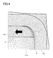
- FIG. 4 is a schematic diagram showing a stress analysis result of a coil end provided with no cavity in a resin molded part in a comparative example
- FIG. 5 is a schematic cross-sectional view of a stator core end portion provided with a cavity in a resin molded part in a comparative example
- FIG. 6 is a model of a stator formed with no cavity in a comparative example
- FIG. 7 is a model formed with an elliptic cutout in a comparative example
- FIG. 8 is a model formed with a cavity in a coil end in the first embodiment
- FIG. 9 is a model having a larger lower thickness in a comparative example.
- FIG. 10 is a graph showing stress analysis results by comparison between the models shown in FIGS. 6 to 9 ;
- FIG. 11 is a schematic cross-sectional view of a stator core in a second embodiment
- FIG. 12 is a schematic cross-sectional view of a stator core in a third embodiment
- FIG. 13 is a schematic cross-sectional view of a stator core in a fourth embodiment
- FIG. 14 is a schematic cross-sectional view of a stator core in a fifth embodiment
- FIG. 15 is a schematic cross-sectional view of a stator core in a sixth embodiment
- FIG. 16 is a diagram showing an analysis result of strain or warp of an insulator in a conventional art
- FIG. 17 is a diagram showing an analysis result of strain or warp of an insulator in the sixth embodiment.
- FIG. 18 is a graph showing stress analysis results by comparison in the sixth embodiment.
- FIG. 19 is a schematic cross-sectional view of a stator core in a seventh embodiment.
- FIG. 1 is a perspective view of a stator in the first embodiment.
- FIG. 2 is a perspective view of a stator segment unit.
- a stator 10 is a split-type stator core including eighteen stator segment units 110 shown in FIG. 2 arranged in an annular form, forming the stator.
- Each stator segment unit 110 includes a core piece (a split-type stator core) 111 , a coil 112 formed of a flat conductor D having a rectangular cross section wound by edgewise bending, a resin molded part 113 , and an insulator 114 .
- the stator 10 has, on a coil end, a bus bar holder 101 .
- An outer ring 102 is fitted or mounted on the outer periphery of the stator segment units 110 .
- Each core piece 111 is formed of electromagnetic steel sheets each made by press work or the like and laminated one on another, and includes a teeth part 111 a protruding from an inner periphery side.
- the coil 112 is formed of the flat conductor D by edgewise bending and includes an outside terminal portion 112 a and an inside terminal portion 112 b on a coil end side.
- the flat conductor D is a wire made of metal having high electric conductivity such as copper and having a rectangular cross section, and coated with insulating resin such as enamel.
- the insulator 114 is formed on the core piece 111 by insert molding.
- the coil 112 is mounted on the insulator 114 , and then the resin molded part 113 is formed by insert molding conducted again.
- the resin molded part 113 and the insulator 114 are made of thermoplastic resin such as PPS resin. Since the insulator 114 is formed on the core piece 111 by insert molding, adhesion strength between the core piece 111 and the insulator 114 can be enhanced.
- the insulator 114 includes side walls 114 a covering the side surfaces of the teeth part 111 a of the core piece 111 and end-face walls 114 b covering the end faces of the teeth part 111 a . Support walls 114 c for supporting the coil 112 are provided on both side edges of each end-face wall 114 b.
- FIG. 3 is a front cross-sectional view of a part of the stator segment unit.
- the thickness of the laminated steel sheets of the teeth part 111 a is illustrated to be thick for easy viewing.
- This figure shows a part of an A-A cross section in FIG. 2 .
- the support walls 114 c supporting the coil 112 are provided on both side edges of the end-face wall 114 b .
- a cavity 120 serving as a stress relaxing section is formed between the walls 114 c .
- the cavity 120 is formed by a protrusion of a molding die protruding from a side corresponding to an outer or inner periphery of the core piece 111 when the resin molded part 113 is formed.
- the cavity 120 is therefore formed to extend through the stator segment unit 110 from an inner periphery side to an outer periphery side. Since the cavity 120 is formed on each end face of the core piece 111 , even though not illustrated, two cavities 120 are formed in each stator segment unit 110 .
- Each cavity 120 formed as above is preferably designed so that a portion of the resin molded part 113 located inside a coil 112 is as thin as possible. However, by the action of insert molding, excess thickness of the resin forming the resin molded part 113 is caused on the inside of the coil 112 , on the upper surface of the end-face wall 114 b , and others. Accordingly, the material thickness is preferably formed as thin as possible.
- the stator 10 of the first embodiment being configured as above can provide the following operations and advantageous effects. Firstly, by the cavity 120 provided in the resin molded part 113 , it is possible to release or relax stress concentration in the resin molded part 113 .
- the stator 10 of the first embodiment includes the coil 112 formed of the wound flat conductor D, the core piece 111 including the teeth part 111 a on which the coil 112 is mounted, and the resin molded part 113 made in such a manner that the coil end portions of the coil 112 mounted on the core piece 111 are covered with resin.
- the insulator 114 is formed by insert molding between the core piece 111 and the coil 112 .
- the resin molded part 113 is provided with the cavities 120 each formed to continuously extend in a radial direction of the stator 10 between the coil 112 and the core piece 111 .
- FIG. 4 is a schematic diagram showing a stress analysis result of a coil end in which a cavity is not provided, illustrating a part corresponding to FIG. 3 . Since the resin molded part and the insulator are made of the same kind of resin, they are illustrated integrally for convenience of analysis.
- the stator 10 not provided with the cavity 120 in the resin molded part 113 , as shown in FIG. 4 , it is found that stress concentrates on a stress concentration area P.
- a shrinkage force F 1 acts on the resin molded part 113 , causing stress to concentrate in the stress concentration area P.
- the resin molded part 113 and the insulator 114 have a high heat shrinkage rate, and a force induces the resin to shrink or contract toward the center of the resin molded part 113 , i.e., leftward in the figure. Further, a force induces the resin molded part 113 to separate or peel from the coil 112 .
- shrinkage force F 1 Due to the generation of such shrinkage force F 1 , stress concentrates and accumulates in the stress concentration area P. This may cause cracks in the resin molded part 113 or the insulator 114 , thereby causing insulation failures between the coil 112 and the teeth part 111 a . However, such a shrinkage force F 1 is relaxed or reduced by the cavity 120 formed in the resin molded part 130 . This results from the reasons that the volume of resin forming the resin molded part 113 is reduced and thus a shrinkage amount of the resin decreases and also that the cavity 120 blocks transmission of the shrinkage force F 1 .
- FIG. 5 is a schematic cross-sectional view of an end portion of the stator core provided with the cavity, corresponding to a part B in FIG. 3 .
- the cavity 120 is provided in the coil end of the stator segment unit 110 of the stator 10 . Because of this, the resin shrinks or contracts by an amount corresponding to the shrinkage of the insulator 114 , so that the shrinkage force F 1 is smaller by a reduced amount of resin which shrinks as compared with the case shown in FIG. 4 . This also diminishes stress concentration in the stress concentration area P.
- FIG. 6 shows a model of a stator formed with no cavity in a conventional art, corresponding to the part B in FIG. 3 .
- FIG. 7 shows a model formed with an elliptic cutout, corresponding to the part B in FIG. 3 .
- FIG. 8 shows a model formed with a cavity in a coil end, corresponding to the part B in FIG. 3 .
- FIG. 9 shows a model formed to have a large lower thickness, corresponding to the part B in FIG. 3 .
- FIG. 10 shows stress analysis results. Analysis models shown in FIGS. 6 to 9 were prepared and subjected to stress analysis on the coil ends of the stators 10 . Results thereof are shown in FIG. 10 . A vertical axis in a graph represents generated stress. An analysis result of the model shown in FIG.
- An analysis result of the model shown in FIG. 7 is labeled by “Elliptic Cutout”.
- An analysis result of the model shown in FIG. 8 is labeled by “Cutout”.
- An analysis result of the model shown in FIG. 9 is labeled by “Cutout with Large Lower Thickness”.
- the stress analysis results reveal that the model formed with the cavity 120 as shown in FIG. 8 achieves a highest stress reduction effect, and this effect is lower in turn in the model including a thick portion under the cavity 120 as shown in FIG. 9 and the model provided with the elliptic cavity 120 .
- the results in FIG. 10 reveal that a lesser amount of resin forming the resin molded part 113 is more effective in reducing stress and further show that a thinner thickness in an axial direction of the stator 10 can provide a better result. Consequently, the first embodiment uses the insulator 114 designed to have the support walls 114 c.
- the stator 10 of the first embodiment can also provide the advantage of reducing the amount of resin to be used for the resin molded part 113 . Since the cavity 120 is provided in each coil end portion of the stator segment unit 110 , the amount of resin to form the resin molded part 113 can be simply reduced. This reduced amount of resin for the resin molded part 113 enables reduction in weight of the stator 10 . Further, the reduced amount of resin to be used can lead to a cost reduction.
- the stator 10 of the first embodiment provided with the cavity 120 in the resin molded part 113 can achieve a cooling effect.
- the motor using the stator 10 is mounted near an engine and hence in an environment where the stator 10 always contacts coolant. Accordingly, the stator 10 can have a surface area increased by the cavities 120 formed in the resin molded part 113 and hence have an increased contact area with the coolant, thereby enhancing the cooling efficient. Due to resistance heating from the coil 112 during use of the stator 10 , there may be caused deterioration in insulating performance of the resin molded part 113 , insulator 114 , and others, degradation in energizing performance of the coil 112 , and other defects. Cooling is thus necessary. Therefore improved cooling efficient of the stator 10 can contribute to an increase in performance of the motor and a longer life of the motor.
- the applicants performed various stress analyses of the stator 10 other than the above analyses. From their results, it was found that the stress reduction effect could be more enhanced by, in addition to the formation of the cavities 120 of the invention, a configuration that the corners of the teeth part 111 a of the core piece 111 of the stator segment unit 110 were rounded off or a combination with a technique of providing a pin or pins on the end face sides of the teeth part 111 a in order to prevent shrinkage of the resin molded part 113 .
- the present invention may be combined with other configurations to provide high stress reduction effects.
- FIG. 11 is a schematic cross-sectional view of a stator core of the second embodiment.
- the insulator 114 of the second embodiment differs from the insulator 114 of the first embodiment in that a breakable groove 114 d corresponding to a breakable portion is provided in the end-face wall 114 b .
- This breakable groove 114 d is provided to extend from an inner periphery side to an outer periphery side of the stator segment unit 110 , that is, in parallel to the cavity 120 .
- the stator segment unit 110 is provided with the breakable grooves 114 d at two portions in each end face, i.e., four portions in total.
- the breakable grooves 114 d are formed at two portion s of each end-face wall 114 b .
- These breakable grooves 114 d are provided near both side end portions of each end-face wall 114 b at corners of the insulator 114 .
- a predetermined distance X 1 is ensured from an end of the end-face wall 114 b . That is, a rib having a width corresponding to the distance X 1 is provided to extend from an end face of the side wall 114 a.
- the stator 10 of the second embodiment configured as above can provide the operations and advantageous effects explained below. Since the insulator 114 is positively broken off at the breakable grooves 114 d , the stress generated in the insulator 114 can be relaxed. In the stator 10 of the second embodiment, the insulator 114 is provided with the breakable grooves 114 d having low strength to be breakable, and the breakable grooves 114 d are formed on the end face side of and in a radial direction of the stator segment unit 110 . Accordingly, if the shrinkage force F 1 is generated due to heat in a usage environment during use of the stator 10 , the breakable grooves 114 d are broken or split. This is because the end-face walls 114 b of the insulator 114 are designed so that portions defining the breakable grooves 114 d are thinnest and easy to break.
- the breakable grooves 114 d may be provided as breakable lines like perforation instead of the groove shape shown in the second embodiment.
- the insulator 114 has only to be configured so that the breakable grooves 114 d are positively broken when the shrinkage force F 1 is generated in the end-face walls 114 b .
- the ribs each having the width corresponding to the distance X 1 are left in the side walls 114 a , the insulating creepage distance between the coil 112 and the core piece 111 can be kept even when a portion corresponding to the breakable groove 114 d is broken.
- breakable grooves 114 d are formed in the insulator 114 , the grooves 114 d are positively broken by the generation of the shrinkage force F 1 , thereby blocking the transmission of the shrinkage force F 1 .
- the force is divided into a right side and a left side of each breakable groove 114 d in FIG. 11 . Consequently, the concentrated stress is less likely to accumulate in the stress concentration area P. Accordingly, it is possible to prevent the generation of cracks which may cause short circuits between the teeth part 111 a and the coil 112 .
- Each breakable groove 114 d formed in the insulator 114 has a shape parallel to the cavities 120 and therefore can be made by mold release when the insulator 114 is made by insert molding. Specifically, the grooves 114 d can be formed by simply changing a molding die for the insulator 114 , so that measures against stress can be realized without increasing cost.
- the third embodiment has a configuration substantially the same as that of the first embodiment excepting a slight difference in the shape of the insulator 114 .
- FIG. 12 is a schematic cross-sectional view of a stator of the third embodiment.
- the insulator 114 of the second embodiment differs from the insulator 114 of the first embodiment in the shape of the end-face walls 114 b .
- Each end-face wall 114 b is formed with only a width corresponding to a distance X 1 .
- the insulator 114 is provided with a rib portion 114 e having a width corresponding to the distance X 1 and extending from and along an end of the side wall 114 a .
- the distance X 1 is set to such an extent as to ensure an insulating creepage distance between the coil 112 and the teeth part 111 a.
- the stator 10 of the third embodiment configured as above can provide the following operations and advantageous effects.
- the end-face walls 114 b of the insulator 114 do not cover all over the end faces of the teeth part 111 a , i.e., the end-face walls 114 b are discontinuously formed, so that the force generated in a direction of shrinkage force F 1 can be restrained.
- the advantageous effects are similar to those in the second embodiment in which the end-face walls 114 b are broken at the breakable grooves 114 d .
- the second embodiment and the third embodiment differ from each other in whether the end-face walls are originally in a broken state or the end-face walls are broken during use.
- the fourth embodiment has a configuration substantially the same as that of the first embodiment excepting a slight difference in a method of manufacturing the stator 10 .
- FIG. 13 is a cross-sectional view of a stator core of the fourth embodiment.
- the stator 10 of the fourth embodiment is provided with a primer material 130 on the inner circumferential side of the coil 112 instead of providing the cavities 120 of the first embodiment.
- This primer material 130 is applied to the inner circumferential surface of the coil 112 after the coil 112 is wound.
- the primer material 130 is preferably selected from high-heat-resistant materials, and herein is an epoxy adhesive. After the primer material 130 is applied to the inner circumferential surface of the coil 112 , the coil 112 is mounted on the teeth part 111 a of the core piece 111 . This assembly is then subjected to insert-molding.
- the core piece 111 is formed with the insulator 114 in advance.
- the primer material 130 can enhance adhesion strength between the coil 112 and the resin molded part 113 present inside the coil 112 .
- the first embodiment describes that the molding die needs to have the protrusions to form the cavities 120 , such a protrusion is not needed in a molding die used in the fourth embodiment formed with no cavity 120 .
- the primer material 130 may be applied after the coil 112 is mounted on the teeth part 111 a.
- the stator 10 of the fourth embodiment configured and manufactured as above can provide the following operations and advantageous effects. Firstly, it is possible to reduce the stress caused due to the heat generated in the stator 10 in a usage environment.
- the method of manufacturing the stator 10 in the fourth embodiment is achieved by winding the flat conductor D to form the coil 112 , mounting the coil 112 on the core piece 111 including the teeth part 111 a , and forming the resin molded part 113 to cover, with resin, the coil end portions of the coil 112 mounted on the core piece 111 .
- the primer material 130 is applied to the inner circumferential surface of the coil end portions of the coil 112 , this coil 112 coated with the primer material 130 is mounted on the teeth part 111 a , and then the resin molded part 113 is formed.
- the primer material 130 is provided on the inner circumferential surface of the coil 112 , a reaction force F 2 can be generated against the shrinkage force F 1 generated as shown in FIG. 13 .
- the heat shrinkage has an influence on a boundary between the coil 112 and the resin molded part 113 . Specifically, when the resin molded part 113 is peeled from the coil 112 , stress is more likely to accumulate in the stress concentration area P.
- the reaction force F 2 is generated by adhesive force of the primer material 130 and elastic force of the coil 112 , so that the generated shrinkage force F 1 consequently acts in a direction to avoid the stress concentration in the stress concentration area P.
- This makes it possible to restrain the concentrated stress from accumulating in the resin molded part 113 or the insulator 114 of the stator 10 and contribute to lengthen the life of the stator 10 .
- the resin molded part 113 and the insulator 114 of a material having a good adhesion property with an insulating coating material of the coil 112 so that the insulating coating material covering the coil 112 and the resin forming the resin molded part 113 and the insulator 114 are less peeled from each other. Even when the materials of the resin molded part 113 and the insulator 114 have a good adhesion property with the insulating coating material covering the coil 112 , the same effect as the application of the primer material 130 can be obtained.
- This method needs no step of applying the primer material 130 can thus contribute to a cost reduction of the stator 10 .
- this method narrows the range of options for the resin to form the resin molded part 113 and the insulator 114 . It is therefore preferable to select the resin in consideration of insulating performance and heat resistance demanded for resin.
- the fifth embodiment has a configuration substantially the same as that of the first embodiment excepting a slight difference in the shape of the teeth part 111 a .
- FIG. 14 is a schematic cross-sectional view of a stator of the fifth embodiment.
- the core piece 111 of the fifth embodiment is designed such that the teeth part 111 a has, at each coil end portion, a shorter width in a circumferential direction of the core piece 111 .
- the width of a first electromagnetic-steel-sheet teeth part 111 a 1 located in an end face of the core piece 111 is designed to be narrower than those of a second electromagnetic-steel-sheet teeth part 111 a 2 and a third electromagnetic-steel-sheet teeth part 111 a 3 as shown in FIG. 14 .
- the stator segment unit 110 can relax stress concentration occurring in a stress concentration area P. Because of the shorter width of the first electromagnetic-steel-sheet teeth part 111 a 1 , the corners of the insulator 114 formed around the teeth part 111 a can be made thicker. Furthermore, as shown in FIG. 14 , each corner of the teeth part 111 a is formed with two shoulders in the first electromagnetic-steel-sheet teeth part 111 a 1 and the second electromagnetic-steel-sheet teeth part 111 a 2 , so that stress concentration areas P of the stress caused by heat influence in a usage environment are dispersed.
- FIG. 15 is a schematic cross-sectional view of a stator of the sixth embodiment.
- the width of the teeth part 111 a in a circumferential direction of the core piece is narrower in a stepped manner, at each coil end portion.
- a teeth width of a first electromagnetic-steel-sheet teeth part 111 a 1 located in an end face of the core piece 111 is narrower than that of a second electromagnetic-steel-sheet teeth part 111 a 2
- the width of this teeth part 111 a 2 is narrower than that of a third electromagnetic-steel-sheet teeth part 111 a 3
- the width of this teeth part 111 a 3 is narrower than that of a fourth electromagnetic-steel-sheet teeth part 111 a 4 .
- the stator segment unit 110 can relax stress concentration occurring in a stress concentration area P.
- each corner of the teeth part 111 a is formed in a more stepped shape than that in the fifth embodiment and thus the stress concentration areas P are dispersed.
- the teeth part 111 a of the sixth embodiment has the corners each formed stepwise with a larger number of shoulders than in the fifth embodiment, so that the stress concentration areas P in the sixth embodiment are more dispersed.
- FIG. 16 shows an analysis result of strain of the insulator in a conventional art.
- FIG. 17 shows an analysis result of strain of the insulator of the sixth embodiment.
- the strain of the insulator 114 is schematically illustrated, in which larger deformation represents larger strain. It is therefore found from comparison between FIGS. 16 and 17 that the strain generated in the insulator 114 in FIG. 17 is relaxed as compared with that in FIG. 16 .
- these stress analysis results reveal that the corners of the teeth part 111 a formed in a stepped shape can reduce the accumulation of stress generated in the stress concentration area P.
- FIG. 18 is a graph showing stress analysis results by comparison.
- a vertical axis represents generated stress.
- An analysis result of the model shown in FIG. 6 , as in FIG. 10 is labeled by “Conventional” for comparison.
- An analysis result of the model shown in FIG. 15 is labeled by “Cutout+Stepped Core”.
- each corner of the teeth part 111 a is designed to disperse stress concentration by setting different widths of the electromagnetic-steel-sheet teeth parts. That is, the first electromagnetic-steel-sheet teeth part 111 a 1 is designed with a narrower width than that of the second electromagnetic-steel-sheet teeth part 111 a 2 . Accordingly, this difference in width directly influences only the insulator 114 . However, since the insulator 114 and the resin molded part 113 are made of resin, the adhesion strength is high, and hence the difference in width indirectly influences the resin molded part 113 . Consequently, the relaxation of stress generated in the resin molded part 113 can be realized by the cavities 120 and the configuration of teeth part 111 a.
- the seventh embodiment has a configuration substantially the same as that of the first embodiment excepting slight differences in resin used as materials of the insulator 114 and resin molded part 113 , configuration of the resin molded part 113 , and so on. The following explanation is given to those differences.
- FIG. 19 is a schematic cross-sectional view of a stator of the seventh embodiment.
- a core piece 111 of the seventh embodiment different from that of the first embodiment, is not formed with the cavities 120 in the resin molded part 130 . Instead thereof, the resin used for the resin molded part 113 and the insulator 114 is adjusted to reduce a difference between the linear expansion coefficient of the teeth part 111 a and the linear expansion coefficients of the resin molded part 113 and the insulator 114 .
- the composition and orientation of filler to be mixed in the resin for the resin molded part 113 or the insulator 114 are adjusted.
- the linear expansion coefficients can be changed by adjusting the flow of resin to form the resin molded part 113 and the insulator 114 .
- the filler to be mixed in the resin is a fibrous reinforcing material and mixed for the purpose of enhancing the strength of the insulator 114 and the strength of the resin molded part 113 , and other purposes. Accordingly, as an amount of mixture of the filler is larger, the linear expansion coefficients of the resin molded part 113 and the insulator 114 are made smaller. Similarly, in the case where the fiber direction of the filler is aligned to the circumferential direction of the stator 10 , the linear expansion coefficient in the circumferential direction of the stator 10 can be decreased.
- the heat shrinkage rate also varies depending on the flowing direction of resin in the insert-molding of the resin molded part 113 and the insulator 114 .
- the linear expansion coefficients of the resin molded part 113 and the insulator 114 can be decreased.
- the linear expansion coefficients of the resin molded part 113 and the insulator 114 are adjusted to become approximate to the linear expansion coefficient of the core piece 111 . Accordingly, the stress generated in the resin molded part 113 and the insulator 114 can be relaxed. This can mitigate the stress accumulating in the stator 10 and keep insulation of the stator 10 .
- the present invention is described in the above embodiments but is not limited thereto.
- the invention may be embodied in other specific forms without departing from the essential characteristics thereof.
- the materials exemplified in the first to fourth embodiments may be changed within a scope of the purpose thereof.
- the configurations may also be changed within a scope of the purpose of the invention.
- the shape of the cavities 120 provided in the resin molded part 113 various patterns are conceivable. Accordingly, the shape of the cavities 120 may be changed to relax the stress concentration occurring in the resin molded part 113 .
- the primer material 130 shown in the fourth embodiment may be combined with other embodiments. For instance, even when the resin molded part 113 is provided with the cavities 120 as disclosed in the first embodiment, the primer material 130 may be applied to the inner circumferential surface of the coil 112 . In this case, the reaction force F 2 as shown in FIG. 13 is generated. Consequently, the stress concentration in the stress concentration area P can be more relaxed.
Landscapes
- Engineering & Computer Science (AREA)
- Power Engineering (AREA)
- Insulation, Fastening Of Motor, Generator Windings (AREA)
- Manufacture Of Motors, Generators (AREA)
- Iron Core Of Rotating Electric Machines (AREA)
Applications Claiming Priority (1)
| Application Number | Priority Date | Filing Date | Title |
|---|---|---|---|
| PCT/JP2010/053529 WO2011108098A1 (fr) | 2010-03-04 | 2010-03-04 | Stator et procédé de fabrication de stator |
Publications (2)
| Publication Number | Publication Date |
|---|---|
| US20120319507A1 US20120319507A1 (en) | 2012-12-20 |
| US9293958B2 true US9293958B2 (en) | 2016-03-22 |
Family
ID=44541782
Family Applications (1)
| Application Number | Title | Priority Date | Filing Date |
|---|---|---|---|
| US13/581,928 Expired - Fee Related US9293958B2 (en) | 2010-03-04 | 2010-03-04 | Stator |
Country Status (5)
| Country | Link |
|---|---|
| US (1) | US9293958B2 (fr) |
| EP (1) | EP2544339B1 (fr) |
| JP (1) | JP5516718B2 (fr) |
| CN (1) | CN102870317B (fr) |
| WO (1) | WO2011108098A1 (fr) |
Cited By (4)
| Publication number | Priority date | Publication date | Assignee | Title |
|---|---|---|---|---|
| US20160241093A1 (en) * | 2015-02-13 | 2016-08-18 | Hamilton Sundstrand Corporation | Lubricant channel on a stator winding support |
| US20190238022A1 (en) * | 2018-01-26 | 2019-08-01 | Milwaukee Electric Tool Corporation | Stepped stator for an electric motor |
| US11043869B2 (en) | 2018-08-08 | 2021-06-22 | Chicony Power Technology Co., Ltd. | Motor stator structure and stator assembly |
| US11901767B2 (en) | 2021-05-14 | 2024-02-13 | Ge Energy Power Conversion Technology Limited | Compaction plate, associated magnetic mass, stator, rotor, rotating electric machine and driving system |
Families Citing this family (32)
| Publication number | Priority date | Publication date | Assignee | Title |
|---|---|---|---|---|
| KR101476022B1 (ko) | 2010-05-26 | 2014-12-24 | 도요타지도샤가부시키가이샤 | 고정자 제조 방법 |
| JP6033573B2 (ja) * | 2012-04-27 | 2016-11-30 | 株式会社ニフコ | ステーター用インシュレーター |
| JP5678968B2 (ja) * | 2013-01-31 | 2015-03-04 | 株式会社安川電機 | ボビン及び回転電機 |
| GB2525157B (en) * | 2014-02-18 | 2016-08-24 | Yasa Motors Ltd | Machine cooling systems |
| JP6210003B2 (ja) * | 2014-03-19 | 2017-10-11 | マツダ株式会社 | ステータコア、回転電機およびステータコアの製造方法 |
| US10432041B2 (en) * | 2015-11-04 | 2019-10-01 | Mitsubishi Electric Corporation | Stator, motor, compressor, and refrigerating and air-conditioning apparatus |
| DE102016222614B4 (de) * | 2016-11-17 | 2024-06-06 | Robert Bosch Gmbh | Stator einer elektrischen Maschine, eine elektrische Maschine, sowie Verfahren zum Herstellen einer solchen |
| WO2018100666A1 (fr) * | 2016-11-30 | 2018-06-07 | 三菱電機株式会社 | Stator pour machine électrique rotative |
| CH713235A2 (fr) * | 2016-12-15 | 2018-06-15 | Gotec Sa | Bobine pour pompe électromagnétique, pompe électromagnétique, procédé de fabrication de bobine et kit de montage de pompe électromagnétique. |
| US11190074B2 (en) * | 2017-01-16 | 2021-11-30 | Honda Motor Co., Ltd. | Insulating member, stator of rotary electric machine, and rotary electric machine |
| CN110546867B (zh) | 2017-02-13 | 2022-05-17 | 株式会社三井高科技 | 定子层叠铁芯的制造方法及定子层叠铁芯 |
| JP6805093B2 (ja) * | 2017-02-13 | 2020-12-23 | 株式会社三井ハイテック | 固定子積層鉄心の製造方法及び固定子積層鉄心 |
| US11843334B2 (en) | 2017-07-13 | 2023-12-12 | Denso Corporation | Rotating electrical machine |
| CN113972807B (zh) | 2017-07-21 | 2023-10-27 | 株式会社电装 | 旋转电机 |
| US20200119599A1 (en) * | 2017-07-28 | 2020-04-16 | Panasonic Intellectual Property Management Co., Ltd. | Motor, fan, and refrigerator |
| JP6922868B2 (ja) | 2017-12-28 | 2021-08-18 | 株式会社デンソー | 回転電機システム |
| DE112018006699T5 (de) | 2017-12-28 | 2020-09-10 | Denso Corporation | Rotierende elektrische Maschine |
| JP6939750B2 (ja) | 2017-12-28 | 2021-09-22 | 株式会社デンソー | 回転電機 |
| JP7006541B2 (ja) | 2017-12-28 | 2022-01-24 | 株式会社デンソー | 回転電機 |
| CN111566904B (zh) | 2017-12-28 | 2023-04-28 | 株式会社电装 | 旋转电机 |
| CN111512519B (zh) | 2017-12-28 | 2022-10-11 | 株式会社电装 | 旋转电机 |
| GB2571107A (en) | 2018-02-16 | 2019-08-21 | Rolls Royce Plc | Metal coil fabrication |
| JP7103057B2 (ja) | 2018-08-23 | 2022-07-20 | トヨタ自動車株式会社 | ロータコア及びその製造方法 |
| JP6727457B1 (ja) * | 2019-03-27 | 2020-07-22 | 三菱電機株式会社 | ステータおよび電動機 |
| JP7383899B2 (ja) * | 2019-03-29 | 2023-11-21 | 株式会社デンソー | 回転電機 |
| JP7298267B2 (ja) * | 2019-04-19 | 2023-06-27 | 株式会社デンソー | 回転電機 |
| JP7268508B2 (ja) * | 2019-07-09 | 2023-05-08 | 株式会社デンソー | コイルモジュール及び電力変換装置 |
| JP7347105B2 (ja) * | 2019-10-16 | 2023-09-20 | 株式会社デンソー | ステータの製造装置、および、ステータの製造方法 |
| EP3855603B1 (fr) * | 2020-01-23 | 2024-07-10 | Etel S.A. | Support d'enroulement à verrouillage élastique pour ensembles bobines préformées d'un moteur électrique |
| DE102020202337A1 (de) | 2020-02-24 | 2021-08-26 | BSH Hausgeräte GmbH | Wäschepflegegerät mit elektrischem Antrieb |
| DE112020006839T5 (de) | 2020-03-05 | 2022-12-15 | Denso Corporation | Rotierende elektrische Maschinen |
| CN113809856B (zh) * | 2021-09-18 | 2022-12-09 | 深圳市京泉华科技股份有限公司 | 一种电机定子 |
Citations (21)
| Publication number | Priority date | Publication date | Assignee | Title |
|---|---|---|---|---|
| JPH06284620A (ja) | 1993-03-30 | 1994-10-07 | Toshiba Corp | 回転電機の絶縁コイル |
| JPH0716557U (ja) | 1993-08-18 | 1995-03-17 | 国産電機株式会社 | 回転電機用積層鉄心 |
| JPH10234150A (ja) | 1997-02-20 | 1998-09-02 | Fujitsu General Ltd | 電動機 |
| JP2001268834A (ja) | 2000-03-17 | 2001-09-28 | Matsushita Electric Ind Co Ltd | 電動機のステータ及びその製造方法 |
| JP2002084697A (ja) | 2000-09-06 | 2002-03-22 | Fujitsu General Ltd | 電動機 |
| US20030098630A1 (en) * | 2001-11-28 | 2003-05-29 | Nissan Motor Co., Ltd. | Stator for motor |
| JP2003289010A (ja) | 2002-03-28 | 2003-10-10 | Hitachi Ltd | 樹脂モールド巻線体 |
| JP2005261147A (ja) | 2004-03-15 | 2005-09-22 | Nissan Motor Co Ltd | 回転電機のステータ構造 |
| US20050269891A1 (en) | 2004-06-04 | 2005-12-08 | Hiroaki Shinoki | Motor and manufacturing method for the same |
| CN1745507A (zh) | 2003-02-14 | 2006-03-08 | 丰田自动车株式会社 | 定子线圈模块及其制造方法和旋转电机 |
| JP2006217707A (ja) | 2005-02-02 | 2006-08-17 | Toyota Motor Corp | 相間絶縁紙およびモータ |
| JP2006217706A (ja) | 2005-02-02 | 2006-08-17 | Jfe Steel Kk | モ−タ回転子磁心 |
| JP2007215334A (ja) | 2006-02-10 | 2007-08-23 | Sumitomo Electric Ind Ltd | 電動機用固定子及び電動機 |
| JP2007244065A (ja) * | 2006-03-07 | 2007-09-20 | Nissan Motor Co Ltd | 集中巻きモータのステータ構造 |
| JP2008113529A (ja) | 2006-10-31 | 2008-05-15 | Mitsui High Tec Inc | 積層鉄心およびその製造方法 |
| JP2008160938A (ja) | 2006-12-21 | 2008-07-10 | Toyota Motor Corp | モータの固定子、及び固定子の製造方法 |
| JP2008199806A (ja) | 2007-02-14 | 2008-08-28 | Yaskawa Electric Corp | モールドステータとその製造方法およびモールドモータ |
| JP2009038918A (ja) | 2007-08-02 | 2009-02-19 | Toyota Motor Corp | ステータおよび回転電機 |
| WO2009025134A1 (fr) * | 2007-08-21 | 2009-02-26 | Toyota Jidosha Kabushiki Kaisha | Stator fendu, moteur, et procédé de fabrication de stator fendu |
| JP2009201314A (ja) * | 2008-02-25 | 2009-09-03 | Mitsubishi Electric Corp | 回転電機の固定子 |
| JP2009261220A (ja) | 2008-03-19 | 2009-11-05 | Toyota Motor Corp | 固定子製造方法 |
Family Cites Families (2)
| Publication number | Priority date | Publication date | Assignee | Title |
|---|---|---|---|---|
| US5470615A (en) * | 1994-03-11 | 1995-11-28 | Axis Usa, Inc. | Bonding and coating methods and apparatus for th coils of dynamo-electric machine parts |
| JP2007205334A (ja) * | 2006-02-06 | 2007-08-16 | Ntn Corp | 斜板式コンプレッサの斜板および斜板式コンプレッサ |
-
2010
- 2010-03-04 CN CN201080065196.2A patent/CN102870317B/zh not_active Expired - Fee Related
- 2010-03-04 WO PCT/JP2010/053529 patent/WO2011108098A1/fr active Application Filing
- 2010-03-04 US US13/581,928 patent/US9293958B2/en not_active Expired - Fee Related
- 2010-03-04 EP EP10847002.2A patent/EP2544339B1/fr not_active Not-in-force
- 2010-03-04 JP JP2012502936A patent/JP5516718B2/ja not_active Expired - Fee Related
Patent Citations (29)
| Publication number | Priority date | Publication date | Assignee | Title |
|---|---|---|---|---|
| JPH06284620A (ja) | 1993-03-30 | 1994-10-07 | Toshiba Corp | 回転電機の絶縁コイル |
| JPH0716557U (ja) | 1993-08-18 | 1995-03-17 | 国産電機株式会社 | 回転電機用積層鉄心 |
| JPH10234150A (ja) | 1997-02-20 | 1998-09-02 | Fujitsu General Ltd | 電動機 |
| JP2001268834A (ja) | 2000-03-17 | 2001-09-28 | Matsushita Electric Ind Co Ltd | 電動機のステータ及びその製造方法 |
| JP2002084697A (ja) | 2000-09-06 | 2002-03-22 | Fujitsu General Ltd | 電動機 |
| US20030098630A1 (en) * | 2001-11-28 | 2003-05-29 | Nissan Motor Co., Ltd. | Stator for motor |
| JP2003289010A (ja) | 2002-03-28 | 2003-10-10 | Hitachi Ltd | 樹脂モールド巻線体 |
| CN1745507A (zh) | 2003-02-14 | 2006-03-08 | 丰田自动车株式会社 | 定子线圈模块及其制造方法和旋转电机 |
| US20060145548A1 (en) | 2003-02-14 | 2006-07-06 | Tetsuo Wakita | Stator coil module, method of manufacturing the same, and electric rotating machine |
| JP2005261147A (ja) | 2004-03-15 | 2005-09-22 | Nissan Motor Co Ltd | 回転電機のステータ構造 |
| US20050269891A1 (en) | 2004-06-04 | 2005-12-08 | Hiroaki Shinoki | Motor and manufacturing method for the same |
| JP2005348553A (ja) | 2004-06-04 | 2005-12-15 | Honda Motor Co Ltd | モータおよびモータの製造方法 |
| JP2006217707A (ja) | 2005-02-02 | 2006-08-17 | Toyota Motor Corp | 相間絶縁紙およびモータ |
| JP2006217706A (ja) | 2005-02-02 | 2006-08-17 | Jfe Steel Kk | モ−タ回転子磁心 |
| JP2007215334A (ja) | 2006-02-10 | 2007-08-23 | Sumitomo Electric Ind Ltd | 電動機用固定子及び電動機 |
| JP2007244065A (ja) * | 2006-03-07 | 2007-09-20 | Nissan Motor Co Ltd | 集中巻きモータのステータ構造 |
| JP2008113529A (ja) | 2006-10-31 | 2008-05-15 | Mitsui High Tec Inc | 積層鉄心およびその製造方法 |
| CN101569079A (zh) | 2006-12-21 | 2009-10-28 | 丰田自动车株式会社 | 电动机定子及定子制造方法 |
| JP2008160938A (ja) | 2006-12-21 | 2008-07-10 | Toyota Motor Corp | モータの固定子、及び固定子の製造方法 |
| US8063518B2 (en) | 2006-12-21 | 2011-11-22 | Toyota Jidosha Kabushiki Kaisha | Motor stator and stator manufacturing method |
| US20090302694A1 (en) | 2006-12-21 | 2009-12-10 | Masataka Asai | Motor stator and stator manufacturing method |
| JP2008199806A (ja) | 2007-02-14 | 2008-08-28 | Yaskawa Electric Corp | モールドステータとその製造方法およびモールドモータ |
| JP2009038918A (ja) | 2007-08-02 | 2009-02-19 | Toyota Motor Corp | ステータおよび回転電機 |
| JP2009072055A (ja) | 2007-08-21 | 2009-04-02 | Toyota Motor Corp | 分割固定子、モータ、及び分割固定子製造方法 |
| US20100187918A1 (en) * | 2007-08-21 | 2010-07-29 | Toyota Jidosha Kabushiki Kaisha | Split stator, motor, and split statior manufacturing method |
| WO2009025134A1 (fr) * | 2007-08-21 | 2009-02-26 | Toyota Jidosha Kabushiki Kaisha | Stator fendu, moteur, et procédé de fabrication de stator fendu |
| US8075825B2 (en) | 2007-08-21 | 2011-12-13 | Toyota Jidosha Kabushiki Kaisha | Split stator segment manufacturing method |
| JP2009201314A (ja) * | 2008-02-25 | 2009-09-03 | Mitsubishi Electric Corp | 回転電機の固定子 |
| JP2009261220A (ja) | 2008-03-19 | 2009-11-05 | Toyota Motor Corp | 固定子製造方法 |
Non-Patent Citations (3)
| Title |
|---|
| International Search Report of PCT/JP2010/053529 mailed May 25, 2010. |
| Machine Translation, Arai et al., JP 2007244065 A, Sep. 20, 2007. * |
| Machine Translation, Maejima, JP 2009201314 A, Sep. 3, 2009. * |
Cited By (4)
| Publication number | Priority date | Publication date | Assignee | Title |
|---|---|---|---|---|
| US20160241093A1 (en) * | 2015-02-13 | 2016-08-18 | Hamilton Sundstrand Corporation | Lubricant channel on a stator winding support |
| US20190238022A1 (en) * | 2018-01-26 | 2019-08-01 | Milwaukee Electric Tool Corporation | Stepped stator for an electric motor |
| US11043869B2 (en) | 2018-08-08 | 2021-06-22 | Chicony Power Technology Co., Ltd. | Motor stator structure and stator assembly |
| US11901767B2 (en) | 2021-05-14 | 2024-02-13 | Ge Energy Power Conversion Technology Limited | Compaction plate, associated magnetic mass, stator, rotor, rotating electric machine and driving system |
Also Published As
| Publication number | Publication date |
|---|---|
| CN102870317A (zh) | 2013-01-09 |
| US20120319507A1 (en) | 2012-12-20 |
| EP2544339A4 (fr) | 2017-03-29 |
| WO2011108098A1 (fr) | 2011-09-09 |
| EP2544339B1 (fr) | 2018-05-30 |
| JP5516718B2 (ja) | 2014-06-11 |
| JPWO2011108098A1 (ja) | 2013-06-20 |
| EP2544339A1 (fr) | 2013-01-09 |
| CN102870317B (zh) | 2015-02-11 |
Similar Documents
| Publication | Publication Date | Title |
|---|---|---|
| US9293958B2 (en) | Stator | |
| US10116180B2 (en) | Rotary electric machine stator | |
| US9184638B2 (en) | Stator structure and stator manufacturing method | |
| JP6373854B2 (ja) | ステータ又はロータ | |
| US9570949B2 (en) | Electric motor with permanent magnet having curved outer wall and flat rear wall | |
| EP2182614B1 (fr) | Composant de câblage de bobine de moteur | |
| US9893594B2 (en) | Armature of rotating electrical machine and method for manufacturing same | |
| JP5533285B2 (ja) | 絶縁部材、ステータの製造方法 | |
| WO2011101986A1 (fr) | Stator et procédé de fabrication de stator | |
| JP2010051087A (ja) | 固定子構造 | |
| JP4631340B2 (ja) | 回転電機 | |
| JP2011120356A (ja) | ステータおよびステータ製造方法 | |
| JP5151309B2 (ja) | 回転電機 | |
| JP7205417B2 (ja) | 固定子の製造方法、固定子の製造装置 | |
| JP6834285B2 (ja) | 回転電機ステータ | |
| CN107636937B (zh) | 旋转电机 | |
| CN111066227B (zh) | 旋转电机的定子及定子的制造方法 | |
| JP2009290955A (ja) | モールドコイル及びモールドコイルの製造方法、モールドコイルを用いてなるステータ | |
| WO2021241113A1 (fr) | Bobine, stator comprenant ladite bobine et moteur | |
| JP2010172083A (ja) | クローポール型モータ | |
| JP7153437B2 (ja) | 回転電機 | |
| JPWO2021241113A5 (fr) | ||
| JP2018068068A (ja) | 回転電機用端末モジュール | |
| JP2009225507A (ja) | コイル用の平角線、ステータおよびモータ |
Legal Events
| Date | Code | Title | Description |
|---|---|---|---|
| AS | Assignment |
Owner name: TOYOTA JIDOSHA KABUSHIKI KAISHA, JAPAN Free format text: ASSIGNMENT OF ASSIGNORS INTEREST;ASSIGNORS:UENO, YASUHIRO;YOSHIMURA, JOJI;NAKANISHI, KOJI;AND OTHERS;REEL/FRAME:028876/0633 Effective date: 20120726 |
|
| STCF | Information on status: patent grant |
Free format text: PATENTED CASE |
|
| FEPP | Fee payment procedure |
Free format text: MAINTENANCE FEE REMINDER MAILED (ORIGINAL EVENT CODE: REM.); ENTITY STATUS OF PATENT OWNER: LARGE ENTITY |
|
| LAPS | Lapse for failure to pay maintenance fees |
Free format text: PATENT EXPIRED FOR FAILURE TO PAY MAINTENANCE FEES (ORIGINAL EVENT CODE: EXP.); ENTITY STATUS OF PATENT OWNER: LARGE ENTITY |
|
| STCH | Information on status: patent discontinuation |
Free format text: PATENT EXPIRED DUE TO NONPAYMENT OF MAINTENANCE FEES UNDER 37 CFR 1.362 |
|
| FP | Expired due to failure to pay maintenance fee |
Effective date: 20200322 |