US9199646B2 - Method and system for a vehicle - Google Patents
Method and system for a vehicle Download PDFInfo
- Publication number
- US9199646B2 US9199646B2 US14/118,924 US201214118924A US9199646B2 US 9199646 B2 US9199646 B2 US 9199646B2 US 201214118924 A US201214118924 A US 201214118924A US 9199646 B2 US9199646 B2 US 9199646B2
- Authority
- US
- United States
- Prior art keywords
- vehicle
- control unit
- downgrade
- speed
- engine
- Prior art date
- Legal status (The legal status is an assumption and is not a legal conclusion. Google has not performed a legal analysis and makes no representation as to the accuracy of the status listed.)
- Active
Links
- 238000000034 method Methods 0.000 title claims abstract description 67
- 238000002485 combustion reaction Methods 0.000 claims abstract description 5
- 239000000446 fuel Substances 0.000 claims description 34
- 230000007423 decrease Effects 0.000 claims description 24
- 238000004590 computer program Methods 0.000 claims description 8
- 238000012876 topography Methods 0.000 claims description 2
- 230000006870 function Effects 0.000 description 22
- 238000004364 calculation method Methods 0.000 description 10
- 230000002829 reductive effect Effects 0.000 description 7
- 230000001133 acceleration Effects 0.000 description 6
- 230000008901 benefit Effects 0.000 description 6
- 230000005484 gravity Effects 0.000 description 4
- 230000009471 action Effects 0.000 description 2
- 238000004891 communication Methods 0.000 description 2
- 230000001186 cumulative effect Effects 0.000 description 2
- 230000000694 effects Effects 0.000 description 2
- 230000007935 neutral effect Effects 0.000 description 2
- 230000002411 adverse Effects 0.000 description 1
- 230000006399 behavior Effects 0.000 description 1
- 230000033228 biological regulation Effects 0.000 description 1
- 230000008859 change Effects 0.000 description 1
- 238000006243 chemical reaction Methods 0.000 description 1
- 230000006835 compression Effects 0.000 description 1
- 238000007906 compression Methods 0.000 description 1
- 230000003247 decreasing effect Effects 0.000 description 1
- 230000001934 delay Effects 0.000 description 1
- 238000012423 maintenance Methods 0.000 description 1
- 230000036961 partial effect Effects 0.000 description 1
- 230000008569 process Effects 0.000 description 1
- 230000001141 propulsive effect Effects 0.000 description 1
- 230000001681 protective effect Effects 0.000 description 1
- 230000009467 reduction Effects 0.000 description 1
- 230000008439 repair process Effects 0.000 description 1
- 239000007858 starting material Substances 0.000 description 1
Images


Classifications
-
- B—PERFORMING OPERATIONS; TRANSPORTING
- B60—VEHICLES IN GENERAL
- B60W—CONJOINT CONTROL OF VEHICLE SUB-UNITS OF DIFFERENT TYPE OR DIFFERENT FUNCTION; CONTROL SYSTEMS SPECIALLY ADAPTED FOR HYBRID VEHICLES; ROAD VEHICLE DRIVE CONTROL SYSTEMS FOR PURPOSES NOT RELATED TO THE CONTROL OF A PARTICULAR SUB-UNIT
- B60W30/00—Purposes of road vehicle drive control systems not related to the control of a particular sub-unit, e.g. of systems using conjoint control of vehicle sub-units
- B60W30/18—Propelling the vehicle
- B60W30/18009—Propelling the vehicle related to particular drive situations
- B60W30/18072—Coasting
-
- B—PERFORMING OPERATIONS; TRANSPORTING
- B60—VEHICLES IN GENERAL
- B60W—CONJOINT CONTROL OF VEHICLE SUB-UNITS OF DIFFERENT TYPE OR DIFFERENT FUNCTION; CONTROL SYSTEMS SPECIALLY ADAPTED FOR HYBRID VEHICLES; ROAD VEHICLE DRIVE CONTROL SYSTEMS FOR PURPOSES NOT RELATED TO THE CONTROL OF A PARTICULAR SUB-UNIT
- B60W10/00—Conjoint control of vehicle sub-units of different type or different function
- B60W10/02—Conjoint control of vehicle sub-units of different type or different function including control of driveline clutches
-
- B—PERFORMING OPERATIONS; TRANSPORTING
- B60—VEHICLES IN GENERAL
- B60W—CONJOINT CONTROL OF VEHICLE SUB-UNITS OF DIFFERENT TYPE OR DIFFERENT FUNCTION; CONTROL SYSTEMS SPECIALLY ADAPTED FOR HYBRID VEHICLES; ROAD VEHICLE DRIVE CONTROL SYSTEMS FOR PURPOSES NOT RELATED TO THE CONTROL OF A PARTICULAR SUB-UNIT
- B60W10/00—Conjoint control of vehicle sub-units of different type or different function
- B60W10/04—Conjoint control of vehicle sub-units of different type or different function including control of propulsion units
- B60W10/06—Conjoint control of vehicle sub-units of different type or different function including control of propulsion units including control of combustion engines
-
- B—PERFORMING OPERATIONS; TRANSPORTING
- B60—VEHICLES IN GENERAL
- B60W—CONJOINT CONTROL OF VEHICLE SUB-UNITS OF DIFFERENT TYPE OR DIFFERENT FUNCTION; CONTROL SYSTEMS SPECIALLY ADAPTED FOR HYBRID VEHICLES; ROAD VEHICLE DRIVE CONTROL SYSTEMS FOR PURPOSES NOT RELATED TO THE CONTROL OF A PARTICULAR SUB-UNIT
- B60W10/00—Conjoint control of vehicle sub-units of different type or different function
- B60W10/10—Conjoint control of vehicle sub-units of different type or different function including control of change-speed gearings
- B60W10/11—Stepped gearings
-
- B—PERFORMING OPERATIONS; TRANSPORTING
- B60—VEHICLES IN GENERAL
- B60W—CONJOINT CONTROL OF VEHICLE SUB-UNITS OF DIFFERENT TYPE OR DIFFERENT FUNCTION; CONTROL SYSTEMS SPECIALLY ADAPTED FOR HYBRID VEHICLES; ROAD VEHICLE DRIVE CONTROL SYSTEMS FOR PURPOSES NOT RELATED TO THE CONTROL OF A PARTICULAR SUB-UNIT
- B60W30/00—Purposes of road vehicle drive control systems not related to the control of a particular sub-unit, e.g. of systems using conjoint control of vehicle sub-units
- B60W30/14—Adaptive cruise control
- B60W30/143—Speed control
-
- B—PERFORMING OPERATIONS; TRANSPORTING
- B60—VEHICLES IN GENERAL
- B60W—CONJOINT CONTROL OF VEHICLE SUB-UNITS OF DIFFERENT TYPE OR DIFFERENT FUNCTION; CONTROL SYSTEMS SPECIALLY ADAPTED FOR HYBRID VEHICLES; ROAD VEHICLE DRIVE CONTROL SYSTEMS FOR PURPOSES NOT RELATED TO THE CONTROL OF A PARTICULAR SUB-UNIT
- B60W50/00—Details of control systems for road vehicle drive control not related to the control of a particular sub-unit, e.g. process diagnostic or vehicle driver interfaces
- B60W50/0097—Predicting future conditions
-
- B—PERFORMING OPERATIONS; TRANSPORTING
- B60—VEHICLES IN GENERAL
- B60W—CONJOINT CONTROL OF VEHICLE SUB-UNITS OF DIFFERENT TYPE OR DIFFERENT FUNCTION; CONTROL SYSTEMS SPECIALLY ADAPTED FOR HYBRID VEHICLES; ROAD VEHICLE DRIVE CONTROL SYSTEMS FOR PURPOSES NOT RELATED TO THE CONTROL OF A PARTICULAR SUB-UNIT
- B60W30/00—Purposes of road vehicle drive control systems not related to the control of a particular sub-unit, e.g. of systems using conjoint control of vehicle sub-units
- B60W30/18—Propelling the vehicle
- B60W30/18009—Propelling the vehicle related to particular drive situations
- B60W30/18072—Coasting
- B60W2030/1809—Without torque flow between driveshaft and engine, e.g. with clutch disengaged or transmission in neutral
-
- B60W2550/142—
-
- B60W2550/143—
-
- B60W2550/402—
-
- B—PERFORMING OPERATIONS; TRANSPORTING
- B60—VEHICLES IN GENERAL
- B60W—CONJOINT CONTROL OF VEHICLE SUB-UNITS OF DIFFERENT TYPE OR DIFFERENT FUNCTION; CONTROL SYSTEMS SPECIALLY ADAPTED FOR HYBRID VEHICLES; ROAD VEHICLE DRIVE CONTROL SYSTEMS FOR PURPOSES NOT RELATED TO THE CONTROL OF A PARTICULAR SUB-UNIT
- B60W2552/00—Input parameters relating to infrastructure
- B60W2552/15—Road slope, i.e. the inclination of a road segment in the longitudinal direction
-
- B—PERFORMING OPERATIONS; TRANSPORTING
- B60—VEHICLES IN GENERAL
- B60W—CONJOINT CONTROL OF VEHICLE SUB-UNITS OF DIFFERENT TYPE OR DIFFERENT FUNCTION; CONTROL SYSTEMS SPECIALLY ADAPTED FOR HYBRID VEHICLES; ROAD VEHICLE DRIVE CONTROL SYSTEMS FOR PURPOSES NOT RELATED TO THE CONTROL OF A PARTICULAR SUB-UNIT
- B60W2552/00—Input parameters relating to infrastructure
- B60W2552/20—Road profile, i.e. the change in elevation or curvature of a plurality of continuous road segments
-
- B—PERFORMING OPERATIONS; TRANSPORTING
- B60—VEHICLES IN GENERAL
- B60W—CONJOINT CONTROL OF VEHICLE SUB-UNITS OF DIFFERENT TYPE OR DIFFERENT FUNCTION; CONTROL SYSTEMS SPECIALLY ADAPTED FOR HYBRID VEHICLES; ROAD VEHICLE DRIVE CONTROL SYSTEMS FOR PURPOSES NOT RELATED TO THE CONTROL OF A PARTICULAR SUB-UNIT
- B60W2556/00—Input parameters relating to data
- B60W2556/45—External transmission of data to or from the vehicle
- B60W2556/50—External transmission of data to or from the vehicle of positioning data, e.g. GPS [Global Positioning System] data
-
- B60W2600/00—
-
- B—PERFORMING OPERATIONS; TRANSPORTING
- B60—VEHICLES IN GENERAL
- B60W—CONJOINT CONTROL OF VEHICLE SUB-UNITS OF DIFFERENT TYPE OR DIFFERENT FUNCTION; CONTROL SYSTEMS SPECIALLY ADAPTED FOR HYBRID VEHICLES; ROAD VEHICLE DRIVE CONTROL SYSTEMS FOR PURPOSES NOT RELATED TO THE CONTROL OF A PARTICULAR SUB-UNIT
- B60W2720/00—Output or target parameters relating to overall vehicle dynamics
- B60W2720/10—Longitudinal speed
- B60W2720/103—Speed profile
-
- Y—GENERAL TAGGING OF NEW TECHNOLOGICAL DEVELOPMENTS; GENERAL TAGGING OF CROSS-SECTIONAL TECHNOLOGIES SPANNING OVER SEVERAL SECTIONS OF THE IPC; TECHNICAL SUBJECTS COVERED BY FORMER USPC CROSS-REFERENCE ART COLLECTIONS [XRACs] AND DIGESTS
- Y02—TECHNOLOGIES OR APPLICATIONS FOR MITIGATION OR ADAPTATION AGAINST CLIMATE CHANGE
- Y02T—CLIMATE CHANGE MITIGATION TECHNOLOGIES RELATED TO TRANSPORTATION
- Y02T10/00—Road transport of goods or passengers
- Y02T10/80—Technologies aiming to reduce greenhouse gasses emissions common to all road transportation technologies
- Y02T10/84—Data processing systems or methods, management, administration
Definitions
- the present invention relates to a method and a system for running a vehicle.
- the invention relates to a method and a system for running a vehicle in situations where a reduced power requirement for propulsion of said vehicle prevails.
- the present invention relates also to a vehicle and to a computer program and a computer program product which implement the method according to the invention.
- Cruise controls are now usual in motor vehicles, e.g. cars, trucks and buses.
- a purpose of a cruise control is to achieve a uniform predetermined vehicle speed, and the cruise control may be of traditional type aiming at constant vehicle speed. This may be achieved by adapting the engine torque to avoid retardation, e.g. by increasing the engine torque uphill.
- a general purpose for cruise control is to achieve convenient running of the vehicle and also greater comfort for its driver.
- a driver of a vehicle with cruise control function usually sets a speed v cc as the speed which he/she wishes the vehicle to maintain until the cruise control function is for any reason deactivated.
- the cruise control determines a reference speed v ref which it demands from the portion of the vehicle's control system which controls the vehicle's engine, e.g. an engine control unit.
- v ref will be equal to the set speed v cc , in which case the vehicle will continually endeavour to maintain the speed v cc set by the driver.
- a cruise control function of this kind thus causes the vehicle to try to maintain the speed set irrespective of whether it is travelling uphill, downhill or on a horizontal running surface. This means that the vehicle may be accelerated over the crest of a hill, only to be immediately braked on a subsequent downgrade to avoid exceeding the set speed. This method is thus an uneconomic way of running the vehicle, particularly in the case of heavy vehicles.
- the main items of expenditure for its routine operation comprise driver pay, repair and maintenance costs and fuel to power the vehicle, and the fuel cost may very greatly affect profitability for an owner of the vehicle, e.g. a haulage company or the like.
- cruise control functions which endeavour to modify the running of the vehicle on the basis of knowledge of the road ahead, so that its fuel consumption can be kept as low as possible.
- This may for example be achieved by means of cruise control functions whereby the reference speed v ref can be allowed to deviate from the speed v cc chosen by the driver, on the basis of knowledge of the vehicle's itinerary, in order thereby to run the vehicle in a more fuel-economising way.
- a look-ahead cruise control is a cruise control which uses knowledge of road sections ahead, i.e. knowledge of the nature of the road ahead of the vehicle, to determine the reference speed signal v ref and thus also to modify the vehicle's speed according to variations of the road along which the vehicle travels.
- Heavy vehicles often have automatically operated gearboxes whereby gear changes are controlled by means of a suitable on-board control system, e.g. a gearbox control system.
- the vehicle's LACC system assistance may also be largely controlled by one or more of the vehicle's control systems so that the vehicle runs as economically as possible, e.g. by somewhat reducing its speed at the end of an upgrade followed by a downgrade on which the vehicle will be subject to a positive force component provided by gravity in the direction of travel and will therefore accelerate again to desired speed.
- An object of the present invention is to propose a method for running a vehicle which can further reduce the fuel consumption of vehicles powered by a combustion engine, particularly on downhill runs.
- the present invention relates to a method for running a vehicle provided with an engine, e.g. a combustion engine, which can selectively be connected to at least one driveshaft to deliver driving force to said driveshaft for propulsion of said vehicle.
- an engine e.g. a combustion engine
- the method comprises
- a speed decrease can be achieved before a downgrade at least partly by opening the power train (so-called freewheeling).
- This makes it possible for the vehicle's speed to be reduced in a fuel-economising way before a downgrade and for the subsequent downgrade to be utilised to accelerate the vehicle again to desired speed.
- Opening the power train instead of merely shutting off fuel supply to the engine results in a fuel saving in that the speed decrease and consequent reduction in fuel consumption can be initiated at an earlier stage than has previously been possible.
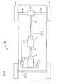
- FIG. 1A depicts a power train in a vehicle in which the present invention may be used
- FIG. 1B depicts a control unit in a vehicle control system
- FIG. 2 depicts an example of a downgrade on which the present invention is applicable
- FIG. 3A depicts a vehicle approaching a downgrade with a gradient angle such that the vehicle will accelerate both when freewheeling and when dragging;
- FIG. 3B depicts schematically the vehicle's respective speeds when freewheeling and dragging on the downgrade depicted in FIG. 3A ;
- FIG. 4 illustrates an example of a method according to the present invention.
- FIG. 1A depicts schematically a power train in a vehicle 100 according to an embodiment of the present invention.
- the power train comprises a combustion engine 101 which in a conventional way is connected, via an output shaft of the engine, usually via a flywheel 102 , to an input shaft 109 of a gearbox 103 via a clutch 106 .
- the clutch may for example take the form of an automatically controlled clutch and be controlled by the vehicle's control system via a control unit 110 .
- the control unit 110 also controls the gearbox 103 .
- the vehicle 100 further comprises driveshafts 104 , 105 which are connected to the vehicle's tractive wheels 113 , 114 and are driven by an output shaft 107 from the gearbox 103 via an axle gear 108 , e.g. a conventional differential.
- the vehicle 100 further comprises various different brake systems, e.g. a conventional service brake system, which may for example comprise brake discs with associated brake linings (not depicted) situated adjacent to each wheel.
- the service brake system is controlled by the vehicle's control system by means of a brake control unit 111 which in a conventional way sends signals to, for example, the regulator or regulators which regulate the braking force in the service brake system.
- the brake control unit 111 may also be adapted to controlling other brake systems on board the vehicle as well as the service brake system. Heavy vehicles are often provided with further brake systems, e.g. in the form of conventional retarders 112 and/or other supplementary brake systems such as various kinds of exhaust brake systems, compression brake systems, electromagnetic brake systems and engine brakes. On the basis of commands initiated by the vehicle's driver and/or other control units, the control unit 111 (or some other suitable control unit) sends control signals to suitable system modules to demand desired braking force from desired brake systems. Supplementary brake systems may also be controlled directly by the driver, e.g. via buttons or pedals, in which case the pedal or lever may be directly connected to another control unit which sends information to, for example, a retarder control unit.
- Control systems in modern vehicles generally comprise a communication bus system consisting of one or more communication buses for connecting together a number of electronic control units (ECUs), or controllers, and various components onboard the vehicle.
- ECUs electronice control units
- Such a control system may comprise a large number of control units and the responsibility for a specific function may be divided between two or more of them.
- Vehicles of the type here concerned are therefore often provided with significantly more control units than depicted in FIG. 1A , as one skilled in the art will surely appreciate.
- the present invention is implemented in the control unit 130 but might also be implemented wholly or partly in one or more other control units already on board the vehicle or a control unit dedicated to the present invention.
- the vehicle depicted in FIG. 1A is also provided with a control unit 130 in which a look-ahead function for using, for example, a so-called “look ahead” cruise control (LACC) as described above is implemented.
- LACC look ahead cruise control
- control exercised by the control unit 110 over the gearbox 103 will thus depend not only upon, for example, an engine control unit 119 but also upon information received from the control unit 130 .
- Control units of the type here concerned are normally adapted to receiving sensor signals from various parts of the vehicle, e.g. the control unit 110 may receive sensor signals from the gearbox 103 and signals from, for example, the brake control unit 111 and the engine control unit 119 as well as the control unit 130 .
- Control units of the type here concerned are also usually adapted to delivering control signals to various vehicle parts and components.
- the control unit 130 delivers signals to the control unit 110 which itself delivers signals to various control devices to demand desired gear ratios in the gearbox 103 and opening/closing of the clutch 106 .
- Control is often governed by programmed instructions, typically in the form of a computer program which, when executed in a computer or a control unit, causes the computer/control unit to effect desired forms of control action, e.g. method steps according to the present invention.
- the computer program usually takes the form of a computer program product 129 which is stored on a digital storage medium 121 (see FIG. 1B ), e.g. ROM (read-only memory), PROM (programmable read-only memory), EPROM (erasable PROM), flash memory, EEPROM (electrically erasable PROM), a hard disc unit etc., in or connected to the control unit, and which is executed by the control unit.
- ROM read-only memory
- PROM programmable read-only memory
- EPROM erasable PROM
- flash memory e.g. EEPROM (electrically erasable PROM), a hard disc unit etc.
- control unit 130 An example of a control unit (the control unit 130 ) is depicted schematically in FIG. 1B , possibly comprising a calculation unit 128 which may for example take the form of some suitable type of processor or microcomputer, e.g. a circuit for digital signal processing (Digital Signal Processor, DSP), or a circuit with a predetermined specific function (Application Specific Integrated Circuit, ASIC).
- the calculation unit 128 is connected to a memory unit 121 which provides it with, for example, the stored program code 129 and/or the stored data which the calculation unit needs for it to be able to perform calculations.
- the calculation unit 128 is also arranged to store partial or final results of calculations in the memory unit 121 .
- the control unit is further provided with respective devices 122 , 123 , 124 , 125 for receiving and sending input and output signals.
- These input and output signals may comprise waveforms, pulses or other attributes which the input signal receiving devices 122 , 125 can detect as information and which can be converted to signals which the calculation unit 128 can process. These signals are therefore conveyed to the calculation unit 128 .
- the output signal sending devices 123 , 124 are arranged to convert signals received from the calculation unit 128 in order, e.g. by modulating them, to create output signals which can be conveyed to other parts of the vehicle's control system and/or the component/components for which the signals are intended.
- Each of the connections to the respective devices for receiving and sending input and output signals may take the form of one or more from among a cable, a data bus, e.g. a CAN (Controller Area Network) bus, an MOST (Media Orientated Systems Transport) bus or some other bus configuration, or a wireless connection.
- a data bus e.g. a CAN (Controller Area Network) bus, an MOST (Media Orientated Systems Transport) bus or some other bus configuration, or a wireless connection.
- the fuel economics of a vehicle may be improved by using an LACC (look-ahead cruise control) function to reduce the vehicle's speed at the end of an upgrade or along a level section of road which precedes a downgrade, in order thereafter to benefit from the reduced driving power requirement on a subsequent downgrade where that requirement is often negative, i.e. such that the vehicle can be accelerated by positive contributions from the force of gravity without fuel having to be supplied to the engine.
- LACC look-ahead cruise control
- Method 400 begins with a step 401 which determines whether the vehicle is approaching a downgrade. This determination may be conducted continuously until it is determined that the vehicle will reach a downgrade within, for example, a certain time, e.g. a certain number of seconds, or within a certain distance, e.g. a certain number of meters, e.g. 100 m, 200 m, 300 m etc.
- an LACC uses knowledge of the itinerary ahead of the vehicle to modify the vehicle's speed according to prevailing circumstances.
- Knowledge of the road section ahead may for example comprise prevailing topography, road curvature, traffic situation, condition of road and speed limitations for the section ahead, and also traffic signs adjacent to the road.
- the LACC function can determine how much time and/or distance remains before a coming downgrade.
- Weather reports/data from weather meters may also be used in calculations described below according to the present invention when for example strong tail/headwinds might affect the driving force required for the vehicle's propulsion.
- FIG. 3A depicts a downgrade 301 with the gradient angle ⁇ which as below is such that the exemplified vehicle 100 would at least accelerate when freewheeling.
- step 401 determines that the vehicle is approaching a downgrade, which may for example be at location A in FIG. 3A , i.e. as early as when the vehicle is still on an upgrade, the method moves on to step 402 .
- speed decrease before a downgrade is effected at least partly by means of freewheeling.
- Dragging means running the vehicle with the power train closed, i.e. with the engine connected to the tractive wheels, but with no fuel supply to the engine.
- An advantage of this type of measure is that since the fuel supply is shut off the engine's fuel consumption will also be nil. It does however mean that the engine will be driven by the tractive wheels via the power train, a situation known as “dragging” in which the engine's internal losses give rise to a braking force, i.e. the vehicle is engine-braked.
- the present invention employs instead freewheeling, which means the vehicle's engine 101 is disconnected from the tractive wheels 113 , 114 , i.e. the power train being opened.
- This disconnection by opening the power train may for example be achieved by putting the gearbox 103 into neutral or by opening the clutch 106 .
- Disconnecting the engine from the tractive wheels when the vehicle is in motion is referred to below as freewheeling. Freewheeling will result in reduced fuel consumption, and the reason for this is described in detail in the parallel Swedish patent application 1150527-8 entitled “Method and system pertaining to vehicles I”, with the same filing date, inventor and applicant as the present application.
- Step 402 therefore determines whether the power train should be opened, and the vehicle thus be caused to freewheel, at location A in order to achieve a desired speed decrease before the downgrade begins, or whether the power train should remain closed with demand for positive driving torque for a further period of time.
- This determination may be done by means of the LACC function and suitable data from the vehicle's control system, e.g. current engine load data from the engine control unit 119 .
- suitable data e.g. current engine load data from the engine control unit 119 .
- the vehicle's weight can be estimated and it is also possible to estimate how its speed will change when the power train is opened.
- step 403 If the power train is not to be opened, the method moves on to step 403 and stays there until a timer t 1 reaches a time T 1 which may for example be one second or a shorter or longer period of time. The period may for example also be controlled by the vehicle's prevailing speed.
- a timer t 1 reaches time T 1 , the method goes back to step 402 for another determination of whether the power train should be opened.
- the vehicle will thus travel a distance corresponding to the time T 1 between determinations at step 402 , such that successive determinations are for location A 1 , A 2 etc. in FIG. 3A .
- step 402 may be done in a number of different ways and on the basis of different criteria. It is for example possible for step 402 to determine how far and/or to what level the vehicle's speed will drop at the beginning of the downgrade if the engine is disconnected from the tractive wheels at locations A (or whatever location the vehicle has reached on the one or more occasions when the time t 1 reaches time T 1 as above, i.e. A 1 , A 2 etc).
- the vehicle's speed is illustrated in FIG. 3B .
- the speed v cc may for example be a speed set by the vehicle's driver, which is also the speed which the vehicle would maintain if it was equipped with a traditional cruise control which would endeavour to ensure that the set speed was maintained both uphill and downhill. It is also the speed which the vehicle maintains (at least) up to location A. If the engine is disconnected at location A, the vehicle's speed will begin to drop and the speed decrease will proceed until at least the location B where the downgrade begins.
- Step 402 may for example determine whether the vehicle's speed is estimated to drop to below a speed v min , and the power train is not opened so long as the result of the estimate is that the vehicle's speed will go below v min .
- the speed v min may for example be a lowest speed considered appropriate to avoiding too much discomfort for the vehicle's driver. If the speed v min is set at too low a value, the driver may also experience stress from fellow road users whose vehicles do not have the benefit of such systems for helping to reduce fuel consumption. If the vehicle's speed is allowed to decrease too much, this may be viewed negatively by the driver.
- the speed v min may also be set with respect to time. If the vehicle's speed is allowed to deviate too much from v cc , its total journey time may be adversely affected, with consequently higher costs in terms of driver pay etc.
- the speed v min may therefore be chosen according to a cost function, e.g. strategies according to the method referred to in Swedish patent application 1050809-1 may be employed.
- the speed v min may also be determined at least partly on the basis of the speed increase which the vehicle is expected to undergo downhill.
- the decision at each step may instead be based on of a cost function.
- a cost function of the type As well as referring to SE1000716 as above, it is possible to use a cost function of the type
- cst A i c 1 ⁇ fuel A i fuel v cc + c 2 ⁇ time A i time v cc to determine power train opening locations.
- cst A i denotes the cost of opening the power train at a location A i , which cost can be compared for different locations A i , making it possible for the power train to be opened at whichever location A i results in lowest cost.
- fuel A i is the cumulative fuel consumption if the power train is opened at location A i
- fuel v cc the cumulative fuel consumption if the vehicle continues running at the speed v cc .
- time A i is the time it takes to drive the vehicle if the power train is opened at location A i
- time v cc is the time it takes to drive the vehicle at the speed v cc
- c 1 ,c 2 are respective weighting constants which regulate the significance of less fuel saving against longer journey time.
- the aggregate of the constants c 1 ,c 2 may for example equal 1.
- Taking decisions according to the cost function may also be subject to certain secondary conditions, e.g. decisions which would result in the vehicle's speed going below v min may be rejected.
- the vehicle's speed if the power train is opened at location A will drop below v min , as illustrated by the broken line v A from location A to location B in FIG. 3B .
- the method therefore, after a determination at location A, moves on to step 403 and stays there for time T 1 before another determination is made. During this period the vehicle will as described above, have traveled to location A 1 . At location A 1 it is still found that the vehicle's speed will drop to too low a level as per the broken line v A1 , so the method again waits for a period T 1 at step 403 for another determination when the vehicle has traveled a little further.
- step 402 determines that the power train should be opened, so the method moves on to step 404 at which the power train is opened immediately, since the vehicle will already be at location A 2 , e.g. by opening the clutch 103 or by putting the gearbox into neutral.
- the vehicle's speed will, as described above, begin to decrease and will at location B reach v min (or at least a speed close to v min , depending on when the power train opening actually takes place, e.g. owing to delays in the system etc.) so that the beginning of the downgrade causes the vehicle to be accelerated again by a positive contribution from the force of gravity as described above.
- a timer is instead immediately incremented by time corresponding to a distance s 1 which may for example be 1 meter, 5 meters, 10 meters, 20 meters or some other suitable distance.
- the distance may for example also be determined by how far the vehicle travels at current speed in a certain time, e.g. a time determined according to the timer t 1 above.
- step 402 determination of the speed which the vehicle will have at location B if the power train is opened at location A i , which means in this embodiment that in practice the estimation is already done before the vehicle reaches location A i .
- the vehicle's speed at location B is already estimated for a plurality of locations A i substantially at location A rather than not until a location A i is reached (the vehicle may of course have left location A before the determination is completed, depending on how long a time the estimation takes).
- the vehicle is in practice expected to reach the location A i determined and the power train can be opened at step 404 .
- step 405 determines how the vehicle should be run when it reaches location B, i.e. when the downgrade begins.
- the engine's internal losses are usually related to its own speed in such a way that they increase with increased engine speed, and hence too the engine braking force, so dragging is usually conducted with as high a gear as possible engaged in the gearbox (i.e. in as low a gear ratio as possible) to reduce the engine's speed, and hence also its losses, during dragging.
- FIG. 2 depicts an example of a downgrade with a gradient angle ⁇ .
- the vehicle will be subject to a greater or smaller positive force in the direction of travel, i.e. the positive contribution from the force of gravity will help to propel the vehicle so the need for driving force from the engine decreases or totally ceases.
- the angle ⁇ in FIG. 2 is smaller than an angle ⁇ F , the vehicle will retard both when dragging and when freewheeling (although in freewheeling it will not be retarded as much as when dragging).
- angle ⁇ amounts to ⁇ S , which is a larger angle than ⁇ F , the vehicle's acceleration during dragging will be nil, i.e. the vehicle will maintain its speed even when dragging. Finally, if the angle ⁇ is larger than ⁇ S , the vehicle will accelerate both when dragging and when freewheeling.
- Step 405 determines whether the power train should again be closed when the vehicle reaches location B. Similar to above, this determination may be arranged to only take place when the vehicle reaches location B, and step 405 may be preceded by a waiting step in which the method stays until the vehicle reaches position B. According to an embodiment, however, the determination commences already before the vehicle reaches location B, as described above in relation to opening the power train. The determination at step 405 may also be conducted by means of the LACC function and data from the vehicle's control system as described above.
- Vehicles of the type here concerned often have an upper speed limit v KFB which is higher than v cc and is not to be exceeded, e.g. because of government regulations or because the vehicle's manufacturer states a maximum speed.
- the speed v KFB may also be set by the vehicle's driver. If this speed is reached, the vehicle will usually automatically begin using supplementary brake systems to ensure that it is not exceeded.
- step 405 therefore determines whether after the vehicle has reached location B it will risk being accelerated by the subsequent downgrade to a speed exceeding said set speed v KFB .
- step 406 This is represented in FIG. 4 by step 406 , which the method stays at until the vehicle's speed drops to v cc , whereupon the power train is closed at step 407 for normal propulsion of the vehicle. The method then goes back to step 401 pending another downgrade.
- step 405 determines that the speed v KFB will be reached on the downgrade, causing one or more of the vehicle's brake systems to be activated to prevent speed increase beyond v KFB , the method moves on to step 408 .
- Step 408 determines whether the speed v KFB will be reached even when the vehicle runs with the power train closed and no fuel supply, i.e. when dragging. If the speed v KFB will be reached even when dragging, the method moves on to step 409 at which the power train is closed when the vehicle reaches location B, since dragging results in less fuel consumption than freewheeling to the location where the speed v KFB is reached. Such a situation is represented in FIG. 3B by a dotted line from location B.
- step 410 determines whether the vehicle has reached location C.
- the method stays at step 410 until the vehicle reaches location C and has therefore passed the downgrade.
- step 411 at which the engine is again disconnected from the tractive wheels to resume freewheeling.
- step 411 the vehicle can freewheel until its speed again drops to v cc .
- the method therefore proceeds from step 411 to step 406 as described above.
- step 408 determines that the speed v KFB will not be reached if the vehicle runs with the power train closed throughout the downgrade, but will be reached when freewheeling as at step 405 , the method moves on to step 412 , which determines whether the speed v KFB will be reached if dragging commences at a time T 2 (or a distance S 2 ) after the vehicle has passed location B.
- the time T 2 /distance S 2 may be any suitable time/distance as above and may for example be a constant or depend on the prevailing gradient angle of the downgrade. This means that the vehicle is allowed to freewheel for a certain time or distance during which it is determined whether it will reach the speed v KFB if it switches to dragging at that time. If such is not the case, a timer t 2 /distance s 2 is incremented by a further interval T 2 /S 2 at step 413 , and another determination is done at step 412 .
- This determination may thus also be conducted by any of the methods described above in relation to steps 402 - 403 , i.e. it may be conducted for the location where the vehicle is at the time, in which case the iteration continues until it is determined that the speed vKFB will be reached, in which case the power train is closed at step 414 when it is found that vKFB will be reached by dragging.
- the determination may take place already before the vehicle reaches location B, with determination of a location for closing the power train (after its opening at location B), and when the vehicle reaches this specific location the power train can be closed at step 414 .
- step 415 determines whether the power train should be reopened. It may for example be found, when the vehicle has accelerated to a speed close to v KFB , that its speed begins to decrease, e.g. because it has reached the end of the downgrade or the gradient angle has decreased. Thus it may be that dragging need only take place for a shorter period before the power train can be reopened to allow acceleration by freewheeling without reaching the speed v KFB . As above, in this situation it is advantageous to open the power train in order to freewheel until the vehicle's speed drops to v cc . When it is thus determined at step 415 that the power train should be opened, this is effected at step 416 and the method then proceeds to step 406 as above.
- the method has also been described above such that the vehicle initially freewheels and thereafter drags if it would reach the speed v KFB when freewheeling but not when dragging.
- the method may however also be the opposite such that the power train is closed at location B before being opened at a location E between B and C for which it is determined that the speed v KFB will not be reached when the power train is opened.
- the method may also involve the power train being opened and closed more than once during a downgrade, depending on its length and/or variations in its gradient angle.
- the above description describes freewheeling according to a method whereby the engine during freewheeling runs at idling speed, resulting in fuel consumption.
- the engine is switched off when freewheeling, resulting in further reduced fuel consumption as compared with situations where the engine is merely disconnected from the driveshafts and situations where the vehicle drags.
- the engine may be switched off for the whole or one or more parts of the period of time when the vehicle is freewheeling.
- the engine is only switched off in situations where it is determined that this is advantageous. It is for example possible to determine whether the engine may be switched off for a first period of time before having to be restarted. This determination may for example be done by means of a look-ahead function as above.
- the period of time may for example be based on the fuel saving achieved by switching said engine off, and may for example be a period which at least results in reduced fuel consumption corresponding to that arising from restarting said engine with a starter motor.
- freewheeling is employed for the whole speed decrease up to the beginning of the downgrade. According to an embodiment, however, freewheeling may be employed to a beginning, in which case the speed decrease may end with dragging.
- the advantage of this is that the speed decrease can be ended quickly, e.g. if it is found that the decrease will take more than a certain time in a situation where a long speed decrease period might cause discomfort to the vehicle's driver.
Landscapes
- Engineering & Computer Science (AREA)
- Transportation (AREA)
- Mechanical Engineering (AREA)
- Chemical & Material Sciences (AREA)
- Combustion & Propulsion (AREA)
- Automation & Control Theory (AREA)
- Human Computer Interaction (AREA)
- Control Of Vehicle Engines Or Engines For Specific Uses (AREA)
- Control Of Transmission Device (AREA)
- Control Of Driving Devices And Active Controlling Of Vehicle (AREA)
- Electrical Control Of Air Or Fuel Supplied To Internal-Combustion Engine (AREA)
Applications Claiming Priority (4)
| Application Number | Priority Date | Filing Date | Title |
|---|---|---|---|
| SE1150529 | 2011-06-10 | ||
| SE1150529A SE537677C2 (sv) | 2011-06-10 | 2011-06-10 | Förfarande och system för framförande av ett fordon |
| SE1150529-4 | 2011-06-10 | ||
| PCT/SE2012/050608 WO2012169962A1 (en) | 2011-06-10 | 2012-06-07 | Method and system for a vehicle |
Publications (2)
| Publication Number | Publication Date |
|---|---|
| US20140088847A1 US20140088847A1 (en) | 2014-03-27 |
| US9199646B2 true US9199646B2 (en) | 2015-12-01 |
Family
ID=46545442
Family Applications (1)
| Application Number | Title | Priority Date | Filing Date |
|---|---|---|---|
| US14/118,924 Active US9199646B2 (en) | 2011-06-10 | 2012-06-07 | Method and system for a vehicle |
Country Status (9)
| Country | Link |
|---|---|
| US (1) | US9199646B2 (sv) |
| EP (1) | EP2718161B1 (sv) |
| JP (1) | JP5745691B2 (sv) |
| KR (1) | KR101604061B1 (sv) |
| CN (1) | CN103608231B (sv) |
| BR (1) | BR112013029641B1 (sv) |
| RU (1) | RU2568151C2 (sv) |
| SE (1) | SE537677C2 (sv) |
| WO (1) | WO2012169962A1 (sv) |
Families Citing this family (13)
| Publication number | Priority date | Publication date | Assignee | Title |
|---|---|---|---|---|
| SE537676C2 (sv) | 2011-06-10 | 2015-09-29 | Scania Cv Ab | Förfarande och system för framförande av ett fordon |
| BR112014012324A2 (pt) * | 2011-12-22 | 2017-05-30 | Scania Cv Ab | método e módulo para controlar uma velocidade do veículo com base em regras e/ou custos |
| SE539476C2 (sv) * | 2012-11-12 | 2017-09-26 | Scania Cv Ab | Förfarande och styrsystem för möjliggörande eller förlängning av en högre transmissionsmod i ett fordon |
| DE102014211560A1 (de) * | 2014-06-17 | 2015-12-17 | Continental Automotive Gmbh | Vorrichtung und Verfahren zur Fahrdynamikregelung eines Kraftfahrzeuges |
| SE539477C2 (sv) * | 2014-07-07 | 2017-09-26 | Scania Cv Ab | Styrning av en förbränningsmotor i samband med frihjulning |
| JP6467888B2 (ja) * | 2014-11-27 | 2019-02-13 | いすゞ自動車株式会社 | 車両の自動走行制御装置及び車両の自動走行方法 |
| KR101704221B1 (ko) * | 2015-06-24 | 2017-02-07 | 현대자동차주식회사 | 차량 주행 제어 방법 |
| US10399569B2 (en) * | 2015-11-03 | 2019-09-03 | Cummins Inc. | Systems and methods for idle coasting management of a vehicle having predictive cruise control |
| CN114312728B (zh) * | 2015-11-04 | 2024-05-03 | 卡明斯公司 | 传动系脱离和滑行管理 |
| DE102015223899B4 (de) | 2015-12-01 | 2020-07-30 | Bayerische Motoren Werke Aktiengesellschaft | Verfahren zum Schalten eines Motorradgetriebes |
| FR3046979B1 (fr) * | 2016-01-27 | 2018-02-02 | Peugeot Citroen Automobiles Sa | Dispositif de regulation adaptative de la vitesse d'un vehicule, a moyens de decision |
| JP7005904B2 (ja) * | 2017-02-03 | 2022-01-24 | いすゞ自動車株式会社 | 走行制御装置、車両および走行制御方法 |
| FR3093691B1 (fr) * | 2019-03-15 | 2021-02-19 | Renault Sas | Procédé de régulation de la vitesse d'un véhicule |
Citations (10)
| Publication number | Priority date | Publication date | Assignee | Title |
|---|---|---|---|---|
| US5754968A (en) * | 1994-03-18 | 1998-05-19 | Scania Cv Aktiebolag | Method and arrangement for fuel quantity adjustment in connection with downshift |
| WO2005084995A1 (en) | 2004-03-09 | 2005-09-15 | Volvo Lastvagnar Ab | Method and system for automatic freewheeling of vehicle |
| US20060046896A1 (en) * | 2004-08-31 | 2006-03-02 | Denso Corporation | Control apparatus for an automatic transmission and related control method |
| US20080015760A1 (en) * | 2004-03-31 | 2008-01-17 | Tomokazu Yamauchi | Power Output Apparatus and Motor Vehicle |
| DE102008023135A1 (de) | 2008-05-09 | 2009-11-12 | Man Nutzfahrzeuge Ag | Verfahren zum Betreiben eines Fahrzeuges, insbesondere eines Nutzfahrzeuges, Steuer- und/oder Auswerteeinrichtung, Fahrerassistenzsystem für ein Nutzfahrzeug sowie Nutzfahrzeug |
| US20100286884A1 (en) * | 2007-11-08 | 2010-11-11 | Jason Robert Bunn | Vehicle system |
| WO2010128898A1 (en) | 2009-05-08 | 2010-11-11 | Volvo Lastvagnar Ab | Method and device for controlling an automatic freewheeling function in a vehicle |
| DE102009057393A1 (de) | 2009-12-08 | 2011-06-09 | Daimler Ag | Verfahren zum Steuern des Betriebs eines Fahrzeugs |
| US20120253617A1 (en) * | 2009-12-17 | 2012-10-04 | Haelleberg Roger | Method and system for driving of a vehicle |
| US20120253619A1 (en) * | 2009-12-17 | 2012-10-04 | Anders Jensen | Method and system for driving of a vehicle |
Family Cites Families (11)
| Publication number | Priority date | Publication date | Assignee | Title |
|---|---|---|---|---|
| JPS6364834A (ja) * | 1986-09-05 | 1988-03-23 | Hino Motors Ltd | 自動トランスミツシヨン |
| RU2010734C1 (ru) * | 1991-07-22 | 1994-04-15 | Могилевский Машиностроительный Институт | Система автоматического управления скоростными и нагрузочными режимами |
| JP2000104578A (ja) * | 1998-09-29 | 2000-04-11 | Nobuhiro Sowa | 省エネ走行可能な自動車 |
| US20050230161A1 (en) * | 2002-08-19 | 2005-10-20 | Shoichi Terui | Traveling body using automatic inertia traveling apparatus |
| JP2005226701A (ja) * | 2004-02-12 | 2005-08-25 | Nissan Diesel Motor Co Ltd | 車両の制御装置 |
| JP4596016B2 (ja) * | 2008-02-12 | 2010-12-08 | トヨタ自動車株式会社 | 車輌走行制御装置 |
| JP2010280281A (ja) * | 2009-06-03 | 2010-12-16 | Toyota Motor Corp | 車両用制御装置 |
| DE102009033866A1 (de) * | 2009-07-17 | 2011-02-03 | Daimler Ag | Verfahren zum Betreiben eines Kraftwagens |
| SE537604C2 (sv) | 2010-07-16 | 2015-07-21 | Scania Cv Ab | Metod för optimering av en parameter i ett motorforon baserad på en kostnadsfunktion, samt styrenhet anordnad att genomföra metoden |
| SE537681C2 (sv) | 2011-06-10 | 2015-09-29 | Scania Cv Ab | Förfarande och system för framförande av ett fordon |
| SE537676C2 (sv) | 2011-06-10 | 2015-09-29 | Scania Cv Ab | Förfarande och system för framförande av ett fordon |
-
2011
- 2011-06-10 SE SE1150529A patent/SE537677C2/sv unknown
-
2012
- 2012-06-07 EP EP12737364.5A patent/EP2718161B1/en active Active
- 2012-06-07 CN CN201280028207.9A patent/CN103608231B/zh active Active
- 2012-06-07 BR BR112013029641-0A patent/BR112013029641B1/pt active IP Right Grant
- 2012-06-07 JP JP2014514840A patent/JP5745691B2/ja active Active
- 2012-06-07 RU RU2014100180/11A patent/RU2568151C2/ru active
- 2012-06-07 WO PCT/SE2012/050608 patent/WO2012169962A1/en active Application Filing
- 2012-06-07 KR KR1020147000678A patent/KR101604061B1/ko active IP Right Grant
- 2012-06-07 US US14/118,924 patent/US9199646B2/en active Active
Patent Citations (12)
| Publication number | Priority date | Publication date | Assignee | Title |
|---|---|---|---|---|
| US5754968A (en) * | 1994-03-18 | 1998-05-19 | Scania Cv Aktiebolag | Method and arrangement for fuel quantity adjustment in connection with downshift |
| WO2005084995A1 (en) | 2004-03-09 | 2005-09-15 | Volvo Lastvagnar Ab | Method and system for automatic freewheeling of vehicle |
| US20060293824A1 (en) * | 2004-03-09 | 2006-12-28 | Volvo Lastvagnar Ab | Method and system for automatic freewheeling of vehicle |
| US20080015760A1 (en) * | 2004-03-31 | 2008-01-17 | Tomokazu Yamauchi | Power Output Apparatus and Motor Vehicle |
| US20060046896A1 (en) * | 2004-08-31 | 2006-03-02 | Denso Corporation | Control apparatus for an automatic transmission and related control method |
| US20100286884A1 (en) * | 2007-11-08 | 2010-11-11 | Jason Robert Bunn | Vehicle system |
| DE102008023135A1 (de) | 2008-05-09 | 2009-11-12 | Man Nutzfahrzeuge Ag | Verfahren zum Betreiben eines Fahrzeuges, insbesondere eines Nutzfahrzeuges, Steuer- und/oder Auswerteeinrichtung, Fahrerassistenzsystem für ein Nutzfahrzeug sowie Nutzfahrzeug |
| WO2010128898A1 (en) | 2009-05-08 | 2010-11-11 | Volvo Lastvagnar Ab | Method and device for controlling an automatic freewheeling function in a vehicle |
| US20120065852A1 (en) * | 2009-05-08 | 2012-03-15 | Volvo Lastvagnar Ab | Method and device for controlling an automatic freewheeling function in a vehicle |
| DE102009057393A1 (de) | 2009-12-08 | 2011-06-09 | Daimler Ag | Verfahren zum Steuern des Betriebs eines Fahrzeugs |
| US20120253617A1 (en) * | 2009-12-17 | 2012-10-04 | Haelleberg Roger | Method and system for driving of a vehicle |
| US20120253619A1 (en) * | 2009-12-17 | 2012-10-04 | Anders Jensen | Method and system for driving of a vehicle |
Non-Patent Citations (1)
| Title |
|---|
| International Search Report mailed Oct. 17, 2012 in corresponding PCT International Application No. PCT/SE2012/050608. |
Also Published As
| Publication number | Publication date |
|---|---|
| EP2718161A1 (en) | 2014-04-16 |
| WO2012169962A1 (en) | 2012-12-13 |
| JP2014516149A (ja) | 2014-07-07 |
| EP2718161B1 (en) | 2016-04-06 |
| CN103608231A (zh) | 2014-02-26 |
| BR112013029641B1 (pt) | 2021-05-25 |
| RU2014100180A (ru) | 2015-07-20 |
| RU2568151C2 (ru) | 2015-11-10 |
| SE1150529A1 (sv) | 2012-12-11 |
| CN103608231B (zh) | 2016-06-01 |
| KR101604061B1 (ko) | 2016-03-25 |
| US20140088847A1 (en) | 2014-03-27 |
| BR112013029641A2 (pt) | 2020-11-17 |
| JP5745691B2 (ja) | 2015-07-08 |
| SE537677C2 (sv) | 2015-09-29 |
| KR20140020356A (ko) | 2014-02-18 |
Similar Documents
| Publication | Publication Date | Title |
|---|---|---|
| US9199646B2 (en) | Method and system for a vehicle | |
| EP2718160B1 (en) | Method and system for a vehicle | |
| US9441555B2 (en) | Method and system for a vehicle | |
| US9821803B2 (en) | Vehicle speed and coasting control method and system | |
| JP4858039B2 (ja) | 車両制御装置 | |
| EP3166829B1 (en) | Control of an combustion engine in a vehicle | |
| US10119488B2 (en) | Control of an internal combustion engine in a vehicle | |
| US10495013B2 (en) | Control of preparatory measures in a vehicle |
Legal Events
| Date | Code | Title | Description |
|---|---|---|---|
| AS | Assignment |
Owner name: SCANIA CV AB, SWEDEN Free format text: ASSIGNMENT OF ASSIGNORS INTEREST;ASSIGNORS:ABDUL-RASOOL, MUSTAFA;JOHANSSON, OSKAR;OGREN, MIKAEL;REEL/FRAME:031637/0475 Effective date: 20131115 |
|
| STCF | Information on status: patent grant |
Free format text: PATENTED CASE |
|
| MAFP | Maintenance fee payment |
Free format text: PAYMENT OF MAINTENANCE FEE, 4TH YEAR, LARGE ENTITY (ORIGINAL EVENT CODE: M1551); ENTITY STATUS OF PATENT OWNER: LARGE ENTITY Year of fee payment: 4 |
|
| MAFP | Maintenance fee payment |
Free format text: PAYMENT OF MAINTENANCE FEE, 8TH YEAR, LARGE ENTITY (ORIGINAL EVENT CODE: M1552); ENTITY STATUS OF PATENT OWNER: LARGE ENTITY Year of fee payment: 8 |