US9140423B2 - Multi-array LED chip for vehicle and head lamp having the same - Google Patents
Multi-array LED chip for vehicle and head lamp having the same Download PDFInfo
- Publication number
- US9140423B2 US9140423B2 US14/157,424 US201414157424A US9140423B2 US 9140423 B2 US9140423 B2 US 9140423B2 US 201414157424 A US201414157424 A US 201414157424A US 9140423 B2 US9140423 B2 US 9140423B2
- Authority
- US
- United States
- Prior art keywords
- vehicle
- led elements
- light
- led
- array
- Prior art date
- Legal status (The legal status is an assumption and is not a legal conclusion. Google has not performed a legal analysis and makes no representation as to the accuracy of the status listed.)
- Active, expires
Links
Images


Classifications
-
- F—MECHANICAL ENGINEERING; LIGHTING; HEATING; WEAPONS; BLASTING
- F21—LIGHTING
- F21S—NON-PORTABLE LIGHTING DEVICES; SYSTEMS THEREOF; VEHICLE LIGHTING DEVICES SPECIALLY ADAPTED FOR VEHICLE EXTERIORS
- F21S41/00—Illuminating devices specially adapted for vehicle exteriors, e.g. headlamps
- F21S41/10—Illuminating devices specially adapted for vehicle exteriors, e.g. headlamps characterised by the light source
- F21S41/14—Illuminating devices specially adapted for vehicle exteriors, e.g. headlamps characterised by the light source characterised by the type of light source
- F21S41/141—Light emitting diodes [LED]
- F21S41/155—Surface emitters, e.g. organic light emitting diodes [OLED]
-
- F21S48/1154—
-
- B—PERFORMING OPERATIONS; TRANSPORTING
- B60—VEHICLES IN GENERAL
- B60Q—ARRANGEMENT OF SIGNALLING OR LIGHTING DEVICES, THE MOUNTING OR SUPPORTING THEREOF OR CIRCUITS THEREFOR, FOR VEHICLES IN GENERAL
- B60Q1/00—Arrangement of optical signalling or lighting devices, the mounting or supporting thereof or circuits therefor
- B60Q1/02—Arrangement of optical signalling or lighting devices, the mounting or supporting thereof or circuits therefor the devices being primarily intended to illuminate the way ahead or to illuminate other areas of way or environments
- B60Q1/04—Arrangement of optical signalling or lighting devices, the mounting or supporting thereof or circuits therefor the devices being primarily intended to illuminate the way ahead or to illuminate other areas of way or environments the devices being headlights
-
- F—MECHANICAL ENGINEERING; LIGHTING; HEATING; WEAPONS; BLASTING
- F21—LIGHTING
- F21S—NON-PORTABLE LIGHTING DEVICES; SYSTEMS THEREOF; VEHICLE LIGHTING DEVICES SPECIALLY ADAPTED FOR VEHICLE EXTERIORS
- F21S41/00—Illuminating devices specially adapted for vehicle exteriors, e.g. headlamps
- F21S41/10—Illuminating devices specially adapted for vehicle exteriors, e.g. headlamps characterised by the light source
- F21S41/14—Illuminating devices specially adapted for vehicle exteriors, e.g. headlamps characterised by the light source characterised by the type of light source
- F21S41/141—Light emitting diodes [LED]
- F21S41/151—Light emitting diodes [LED] arranged in one or more lines
- F21S41/153—Light emitting diodes [LED] arranged in one or more lines arranged in a matrix
-
- F—MECHANICAL ENGINEERING; LIGHTING; HEATING; WEAPONS; BLASTING
- F21—LIGHTING
- F21S—NON-PORTABLE LIGHTING DEVICES; SYSTEMS THEREOF; VEHICLE LIGHTING DEVICES SPECIALLY ADAPTED FOR VEHICLE EXTERIORS
- F21S41/00—Illuminating devices specially adapted for vehicle exteriors, e.g. headlamps
- F21S41/10—Illuminating devices specially adapted for vehicle exteriors, e.g. headlamps characterised by the light source
- F21S41/14—Illuminating devices specially adapted for vehicle exteriors, e.g. headlamps characterised by the light source characterised by the type of light source
- F21S41/18—Combination of light sources of different types or shapes
-
- F—MECHANICAL ENGINEERING; LIGHTING; HEATING; WEAPONS; BLASTING
- F21—LIGHTING
- F21S—NON-PORTABLE LIGHTING DEVICES; SYSTEMS THEREOF; VEHICLE LIGHTING DEVICES SPECIALLY ADAPTED FOR VEHICLE EXTERIORS
- F21S41/00—Illuminating devices specially adapted for vehicle exteriors, e.g. headlamps
- F21S41/20—Illuminating devices specially adapted for vehicle exteriors, e.g. headlamps characterised by refractors, transparent cover plates, light guides or filters
- F21S41/25—Projection lenses
- F21S41/255—Lenses with a front view of circular or truncated circular outline
-
- F—MECHANICAL ENGINEERING; LIGHTING; HEATING; WEAPONS; BLASTING
- F21—LIGHTING
- F21S—NON-PORTABLE LIGHTING DEVICES; SYSTEMS THEREOF; VEHICLE LIGHTING DEVICES SPECIALLY ADAPTED FOR VEHICLE EXTERIORS
- F21S41/00—Illuminating devices specially adapted for vehicle exteriors, e.g. headlamps
- F21S41/60—Illuminating devices specially adapted for vehicle exteriors, e.g. headlamps characterised by a variable light distribution
- F21S41/65—Illuminating devices specially adapted for vehicle exteriors, e.g. headlamps characterised by a variable light distribution by acting on light sources
- F21S41/663—Illuminating devices specially adapted for vehicle exteriors, e.g. headlamps characterised by a variable light distribution by acting on light sources by switching light sources
-
- F21S48/115—
-
- F21S48/1195—
-
- F21S48/1225—
-
- F—MECHANICAL ENGINEERING; LIGHTING; HEATING; WEAPONS; BLASTING
- F21—LIGHTING
- F21V—FUNCTIONAL FEATURES OR DETAILS OF LIGHTING DEVICES OR SYSTEMS THEREOF; STRUCTURAL COMBINATIONS OF LIGHTING DEVICES WITH OTHER ARTICLES, NOT OTHERWISE PROVIDED FOR
- F21V19/00—Fastening of light sources or lamp holders
- F21V19/001—Fastening of light sources or lamp holders the light sources being semiconductors devices, e.g. LEDs
-
- B—PERFORMING OPERATIONS; TRANSPORTING
- B60—VEHICLES IN GENERAL
- B60Q—ARRANGEMENT OF SIGNALLING OR LIGHTING DEVICES, THE MOUNTING OR SUPPORTING THEREOF OR CIRCUITS THEREFOR, FOR VEHICLES IN GENERAL
- B60Q2300/00—Indexing codes for automatically adjustable headlamps or automatically dimmable headlamps
- B60Q2300/05—Special features for controlling or switching of the light beam
- B60Q2300/056—Special anti-blinding beams, e.g. a standard beam is chopped or moved in order not to blind
-
- F—MECHANICAL ENGINEERING; LIGHTING; HEATING; WEAPONS; BLASTING
- F21—LIGHTING
- F21W—INDEXING SCHEME ASSOCIATED WITH SUBCLASSES F21K, F21L, F21S and F21V, RELATING TO USES OR APPLICATIONS OF LIGHTING DEVICES OR SYSTEMS
- F21W2102/00—Exterior vehicle lighting devices for illuminating purposes
Definitions
- the present invention relates to a multi-array LED chip for a vehicle and a head lamp having the same, and more particularly, to a multi-array LED chip for a vehicle and a head lamp having the multi-array LED chip which is installed in the head lamp of the vehicle to prevent light blindness to a driver in an oncoming vehicle, and to improve visibility for a driver in a vehicle.
- lighting devices are provided in a vehicle in order to stably secure visibility of a driver even when illumination is low at the periphery of the vehicle at the time of driving a vehicle, and among the lighting devices, an LED head lamp using a light emitting diode (LED) as a light source of a head lamp has been developed.
- LED light emitting diode
- the LED is a diode that emits excess energy as light when injected electrons and holes are coupled again, emits red light or green light, and is mainly used as a light source using advantages of low pressure and low electric power consumption.
- an LED array is a type of a light source formed by mounting a plurality of LEDs, and may directly implement various beam patterns by selectively turning on the plurality of LEDs.
- the LED array may be applied to a head lamp and a rear lamp of the vehicle so as to be effectively used to implement various beam patterns.
- a light concentration structure 10 of the LED head lamp may include an LED light source 11 , a reflection mirror 12 which adjusts a direction of light from the LED light source 11 , a lens 13 which protects the LED light source 11 , and a shade or shield 14 which cuts off light emitted toward an opposite vehicle so as to prevent light blindness to a driver in an oncoming vehicle.
- an L-shaped beam pattern which is implemented by the shield 14 , may implement a glare free high beam on the basis of both interfaces of left and right head lamps, but there is a drawback in that visibility deteriorates because the light corresponding to an intermediate region exists as a dark zone
- an LED light source which directly emits light to the lens 13 , is used.
- LED elements which are used as the LED light source, are designed to have the same size, and emit light to a front side of the vehicle.
- the LEDs disposed in a predetermined region are turned on and off.
- the oncoming vehicle refers to a vehicle that moves toward another moving vehicle while facing the moving vehicle
- the preceding vehicle means a vehicle that precedes the moving vehicle on a road on which the moving vehicle moves.
- the LED elements having the same light emitting area are turned on and off, and thereby, the LED element has a limit to implement a function of preventing light blindness.
- the screen angle for preventing light blindness against the oncoming vehicle 3 is slowly increased in a range of 1,000 to 200 m, and then rapidly increased from a location of 200 m.
- the moving vehicle 2 has the LED elements having the same light emitting area as the light source, it is possible to prevent light blindness to the driver in the oncoming vehicle 3 when the oncoming vehicle 3 is moving, but there is a problem in that visibility of the driver in the vehicle 2 .
- the present invention has been made in an effort to provide a multi-array LED chip for a vehicle and a head lamp having the multi-array LED chip which secure visibility at a front side and prevent light blindness to a driver in a vehicle moving at the front side by controlling a plurality of LED elements having different sizes to be individually turned on and off.
- the present invention has been made in an effort to provide a multi-array LED chip for a vehicle and a head lamp having the multi-array LED chip capable of improving light efficiency by varying sizes of LED elements that are individually turned on and off so as to correspond to a location of a vehicle moving at a front side.
- An exemplary embodiment of the present invention provides a multi-array LED chip for a vehicle, including a plurality of LED elements arranged and installed to emit light, in which widths of the LED elements are increased in a width direction on the basis of a center of the light.
- the LED elements may include central LED elements, and variable LED elements arranged at both sides of the central LED elements, and widths of the variable LED elements may be increased in the width direction on the basis of the center of the light.
- the plurality of LED elements may be arranged in at least two rows.
- the LED elements may be individually turned on and off.
- Another exemplary embodiment of the present invention provides a multi-array LED chip for a vehicle, including a plurality of LED elements arranged and installed to emit light, in which heights of the LED elements are decreased in a width direction on the basis of a center of the light.
- the LED elements may include central LED elements, and variable LED elements arranged at both sides of the central LED elements, and heights of the variable LED elements may be decreased in the width direction on the basis of the center of the light.
- the LED elements may be individually turned on and off.
- Yet another exemplary embodiment of the present invention provides a multi-array LED chip for a vehicle, including a plurality of LED elements arranged and installed to emit light, in which widths of the LED elements are increased and heights of the LED elements are decreased in a width direction on the basis of a center of the light.
- the LED elements may include central LED elements, and variable LED elements arranged at both sides of the central LED elements, and widths of the variable LED elements may be increased and heights of the variable LED elements are decreased in the width direction on the basis of the center of the light.
- the LED elements may be individually turned on and off.
- Still another exemplary embodiment of the present invention provides a head lamp including: the aforementioned multi-array LED chip for a vehicle; and a lens installed on a light emission line of light emitted from the multi-array LED chip for a vehicle.
- the lens may be an aspherical lens.
- the head lamp may further include a primary optic installed on the light emission line between the multi-array LED chip for a vehicle and the lens.
- the multi-array LED chip for a vehicle and the head lamp having the multi-array LED chip for a vehicle according to the exemplary embodiment of the present invention which have the aforementioned configuration, secure visibility at a front side and prevent light blindness to a driver in a vehicle moving at the front side by controlling a plurality of LED elements having different sizes to be individually turned on and off.
- light efficiency of the head lamp may be improved by varying sizes of the LED elements that are individually turned on and off so as to correspond to a location of the vehicle moving at a front side.
- the LED elements which are arranged in at least two rows, are individually turned on and off so as to correspond to an oncoming vehicle that approaches a front side of the vehicle, thereby improving light efficiency of the vehicle.
- the head lamp having the multi-array LED chip for a vehicle includes a primary optic, thereby improving light quality by concentrating light emitted from the multi-array LED chip for a vehicle into a center, or allowing the light to uniformly enter a lens.
- FIG. 1 is a view illustrating a light distribution structure of an LED head lamp for a vehicle in the related art.
- FIG. 2 is a view illustrating a relationship between a moving vehicle and an oncoming vehicle or a preceding vehicle.
- FIG. 3 is a view illustrating a screen angle with respect to an oncoming vehicle.
- FIG. 4 is a view illustrating a multi-array LED chip for a vehicle according to an exemplary embodiment of the present invention and a head lamp having the multi-array LED chip.
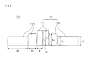
- FIGS. 5 to 8 are views illustrating exemplary embodiments of LED elements that are installed on the multi-array LED chip for a vehicle according to the exemplary embodiment of the present invention.
- a head lamp 1 having a multi-array LED chip for a vehicle may include a multi-array LED chips 100 , 100 a , and 100 b for a vehicle, a lens part 200 , and a heat radiating part 300 .
- the multi-array LED chips 100 , 100 a , and 100 b for a vehicle are installed in the head lamp 1 and emit light as a light source.
- a plurality of LED elements 110 , 110 a , and 110 b is arranged and installed on the multi-array LED chips 100 , 100 a , and 100 b for a vehicle.
- the LED elements 110 , 110 a , and 110 b are aligned and installed on a vertical plane based on a light emission direction.
- the LED elements 110 , 110 a , and 110 b and the multi-array LED chips 100 , 100 a , and 100 b for a vehicle will be described with reference to FIGS. 5 to 8 .
- the LED elements 110 may include central LED elements 111 installed at a center O1 side of the light, and a plurality of variable LED elements 112 disposed at both sides of the central LED elements 111 .
- the plurality of LED elements 110 may be installed to have widths d 1 , d 2 , d 3 , d 4 , d 5 , and d 6 that are increased in a width direction of the multi-array LED chip 100 for a vehicle on the basis of the center O1 of the light. That is, the plurality of LED elements 110 may be installed to have the widths d 1 , d 2 , d 3 , d 4 , d 5 , and d 6 that are decreased as being closer to, the center O1 of the light.
- the central LED elements 111 are disposed at the center O1 side of the light.
- the plurality of variable LED elements 112 having the increased widths d 2 , d 3 , d 4 , d 5 , and d 6 may be disposed at both sides on the basis of the central LED elements 111 having the width d 1 .
- d 1 may be 0.4 ⁇ 0.2 mm
- d 2 may be 0.6 ⁇ 0.2 mm
- d 3 may be 0.8 ⁇ 0.2 mm
- d 4 may be 1.0 ⁇ 0.2 mm
- d 5 may be 2.5 ⁇ 0.2 mm
- d 6 may be 4.0 ⁇ 0.2 mm.
- the LED elements 110 have the same height h of 2.0 ⁇ 0.2 mm.
- the central LED elements 111 which has the width d 1 corresponding to an oncoming vehicle 3 , are turned off when the oncoming vehicle 3 is positioned at a distal location, and the variable LED elements 112 , which have the widths d 2 , d 3 , d 4 , d 5 , and d 6 in a direction toward the oncoming vehicle 3 , are sequentially turned off as the oncoming vehicle 3 approaches a vehicle 2 , thereby preventing light blindness to a driver in the oncoming vehicle 3 .
- the present invention exemplifies the LED elements 110 having the different widths d 1 , d 2 , d 3 , d 4 , d 5 , and d 6 , as illustrated in FIG. 5 , but the present invention is not particularly limited thereto, and the number of LED elements 110 may vary depending on the head lamp 1 that is installed in the vehicle 2 .
- the LED elements 110 which have the widths that are increased in the width direction of the multi-array LED chip 100 for a vehicle on the basis of the center O1 of the light, are sequentially turned on and off so as to correspond to a screen angle for the oncoming vehicle 3 , thereby preventing light blindness to the driver in the oncoming vehicle 3 and improving light efficiency of the vehicle 2 . Therefore, visibility of a driver in the vehicle 2 may be secured.
- the plurality of central LED elements 111 is disposed at the center O1 side of the light.
- the plurality of variable LED elements 112 having the increased widths d 4 , d 5 , and d 6 may be disposed at both sides on the basis of the plurality of central LED elements 111 having the width d 1 .
- d 1 may be 0.4 ⁇ 0.2 mm
- d 4 may be 1.0 ⁇ 0.2 mm
- d 5 may be 2.5 ⁇ 0.2 mm
- d 6 may be 4.0 ⁇ 0.2 mm.
- the LED elements 110 have the same height h of 2.0 ⁇ 0.2 mm.
- the screen angle for preventing light blindness against the oncoming vehicle 3 is slowly increased within a range of 1,000 to 200 m, and thus, the central LED elements 111 , which have the same width so as to correspond to the range of 1,000 to 200 m, may be disposed.
- the screen angle for preventing light blindness against the oncoming vehicle 3 is rapidly increased from a location of 200 m, and thus, the plurality of variable LED elements 112 , which has the widths d 4 , d 5 , and d 6 that are increased to correspond to the screen angle, is disposed, thereby efficiently preventing light blindness to the driver in the oncoming vehicle 3 .
- the central LED elements 111 which have the width d 1 corresponding to the oncoming vehicle 3 , are turned on and off, thereby improving visibility of the driver in the vehicle 2 .
- the variable LED elements 112 having the widths d 4 , d 5 , and d 6 are sequentially turned on and off, thereby preventing light blindness to the driver in the oncoming vehicle 3 and securing visibility at a front side of the vehicle 2 .
- the LED elements 110 may be arranged in at least two rows.
- the LED elements 110 which correspond to the screen angle for the oncoming vehicle 3 and are positioned at an upper side, may be turned off.
- the LED elements 110 which are positioned at a lower side, may also be turned off depending on a size and an approaching location of the oncoming vehicle 3 .
- the screen angle for the oncoming vehicle 3 is increased in a height direction as well as the width direction as the oncoming vehicle 3 approaches the vehicle 2 , and thus, only the LED elements 110 , which are positioned at the upper side, are turned off when the oncoming vehicle 3 is positioned at a distal location, thereby securing light efficiency.
- the LED elements 110 which are positioned at the lower side, need to be turned off as the oncoming vehicle 3 approaches the vehicle 2 , the LED elements 110 , which are positioned at the upper side, may also be turned off, thereby preventing light blindness to the driver in the oncoming vehicle 3 .
- the head lamp 1 may prevent light blindness to the driver in the oncoming vehicle 3 and improve light efficiency of the vehicle 2 as the oncoming vehicle 3 approaches, thereby securing a visual range of the driver in the vehicle 2 .
- each of the LED elements 110 may be individually turned on and off, and then the LED elements 110 may be installed on the multi-array LED chip 100 for a vehicle. Accordingly, each of the LED elements 110 may be individually turned on and off and may be individually inspected.
- a plurality of LED elements 110 a which has heights h 1 , h 2 , and h 3 that are decreased in the width direction of the multi-array LED chip 100 a for a vehicle on the basis of the center O2 of the light, may be installed.
- h 1 may be 4.0 ⁇ 0.2 mm
- h 2 may be 3.0 ⁇ 0.2 mm
- h 3 may be 2.0 ⁇ 0.2 mm.
- the LED elements 110 a have the same width d of 0.5 ⁇ 0.2 mm.
- the screen angle for the oncoming vehicle 3 is increased in the height direction as well as the width direction as the oncoming vehicle 3 approaches the vehicle 2 , and thus, the LED elements 110 a , which have heights that are increased toward a center O2 of the light, are disposed, such that the head lamp 1 may secure visibility of the driver in the vehicle 2 .
- the LED elements 110 a may include central LED elements ill installed at the center O2 side of the light, and a plurality of variable LED elements 112 a disposed at both sides of the central LED elements 111 .
- variable LED elements 112 a In the case of the variable LED elements 112 a illustrated in FIG. 7 , heights h 2 and h 3 of the variable LED elements 112 a become smaller than a height h 1 of the central LED elements 111 in the width direction of the multi-array LED chip 100 a for a vehicle on the basis of the center O2 of the light.
- the central LED elements 111 are disposed at the center O2 side of the light, and the variable LED elements 112 a , which have the heights that are decreased in the width direction, are disposed at both sides of the central LED elements 111 , thereby securing visibility of the driver when the LED elements 110 a are individually turned on and off.
- the present invention exemplifies the six LED elements 110 a having varied heights, but the present invention is not particularly limited thereto, and the number of LED elements 110 a may vary depending on the head lamp 1 that is installed in the vehicle 2 .
- plurality of LED elements 110 b which has widths that are increased and heights h 1 , h 2 , and h 3 that are decreased in the width direction of the multi-array LED chip 100 b for a vehicle on the basis of the center O2 of the light, may be installed.
- h 1 may be 4.0 ⁇ 0.2 mm
- h 2 may be 3.0 ⁇ 0.2 mm
- h 3 may be 2.0 ⁇ 0.2 mm
- w 1 may be 0.5 ⁇ 0.2 mm
- w 2 may be 1.0 ⁇ 0.2 mm
- w 3 may be 3.0 ⁇ 0.2 mm.
- the screen angle for the oncoming vehicle 3 is increased in the height direction as well as the width direction as the oncoming vehicle 3 approaches the vehicle 2 , and thus, the LED elements 110 b , which have the widths that are decreased toward the center O2 of the light and the heights that are increased toward the center O2 of the light, are disposed, such that the head lamp 1 may prevent light blindness to the driver in the oncoming vehicle 3 and secure visibility of the driver in the vehicle 2 .
- the LED elements 110 b may include central LED elements 111 installed at the center O2 side of the light, and a plurality of variable LED elements 112 b disposed at both sides of the central LED elements 111 .
- the LED elements 110 b illustrated in FIG. 8 have the widths that are increased, and the heights h 1 , h 2 , and h 3 that are decreased in the width direction, thereby further improving light efficiency when the oncoming vehicle 3 is positioned at a proximal location.
- the present invention exemplifies the six LED elements 110 b having varied widths and heights, but the present invention is not particularly limited thereto, and the number of LED elements 110 b may vary depending on the head lamp 1 that is installed in the vehicle 2 .
- the lens part 200 is installed on a light emission line of light emitted from the multi-array LED chips 100 , 100 a , and 100 b for a vehicle.
- the lens part 200 may include a lens holder 220 that fixes a lens 210 and a lens 210 .
- the lens 210 may be an aspherical lens.
- the light emitted from the multi-array LED chips 100 , 100 a , and 100 b for a vehicle is guided into an irradiation range of the lens 210 .
- the heat radiating part 300 may be provided to cool heat generated when the multi-array LED chips 100 , 100 a , and 100 b for a vehicle emit light.
- the heat radiating part 300 has a plurality of heat radiating fins (a reference numeral is omitted) so as to disperse and cool heat generated from the multi-array LED chips 100 , 100 a , and 100 b for a vehicle.
- the head lamp 1 may further include a primary optic.
- the primary optic may be installed between the multi-array LED chips 100 and 100 a for a vehicle and the lens 210 . That is, the primary optic is positioned on a light emission line of the multi-array LED chips 100 and 100 a for a vehicle.
- the primary optic may concentrate light emitted from the multi-array LED chips 100 , 100 a , and 100 b for a vehicle into a center, or may diffuse light emitted to an unnecessary portion.
- the primary optic may improve light efficiency using refraction and reflection, and may improve light quality by allowing the light to uniformly enter the lens 200 .
- the primary optic may improve light quality of the light emitted from the head lamp 1 .
- the head lamp 1 has been described in association with the oncoming vehicle 3 , but even in the case of a preceding vehicle 4 that is a vehicle which precedes the vehicle 2 on a road on which the vehicle 2 moves, the head lamp 1 may be identical depending on a location of the preceding vehicle 4 .
Landscapes
- Engineering & Computer Science (AREA)
- General Engineering & Computer Science (AREA)
- Physics & Mathematics (AREA)
- Microelectronics & Electronic Packaging (AREA)
- Optics & Photonics (AREA)
- Mathematical Physics (AREA)
- Mechanical Engineering (AREA)
- Lighting Device Outwards From Vehicle And Optical Signal (AREA)
- Non-Portable Lighting Devices Or Systems Thereof (AREA)
Applications Claiming Priority (2)
| Application Number | Priority Date | Filing Date | Title |
|---|---|---|---|
| KR10-2013-0142932 | 2013-11-22 | ||
| KR1020130142932A KR101606772B1 (ko) | 2013-11-22 | 2013-11-22 | 차량용 멀티 어레이 엘이디 칩 및 이를 구비하는 헤드램프 |
Publications (2)
| Publication Number | Publication Date |
|---|---|
| US20150146448A1 US20150146448A1 (en) | 2015-05-28 |
| US9140423B2 true US9140423B2 (en) | 2015-09-22 |
Family
ID=53182545
Family Applications (1)
| Application Number | Title | Priority Date | Filing Date |
|---|---|---|---|
| US14/157,424 Active 2034-04-07 US9140423B2 (en) | 2013-11-22 | 2014-01-16 | Multi-array LED chip for vehicle and head lamp having the same |
Country Status (3)
| Country | Link |
|---|---|
| US (1) | US9140423B2 (zh) |
| KR (1) | KR101606772B1 (zh) |
| CN (1) | CN104654175A (zh) |
Families Citing this family (11)
| Publication number | Priority date | Publication date | Assignee | Title |
|---|---|---|---|---|
| CN108291701A (zh) * | 2015-11-20 | 2018-07-17 | 株式会社小糸制作所 | 灯具单元 |
| JP2018142595A (ja) * | 2017-02-27 | 2018-09-13 | パナソニックIpマネジメント株式会社 | 光源モジュール、照明装置、及び移動体 |
| KR102327020B1 (ko) * | 2017-03-30 | 2021-11-17 | 에스엘 주식회사 | 차량용 헤드 램프 |
| KR101970249B1 (ko) * | 2017-05-29 | 2019-04-18 | 엘지전자 주식회사 | 차량용 램프 및 차량 |
| KR101989101B1 (ko) * | 2017-05-29 | 2019-06-13 | 엘지전자 주식회사 | 차량용 램프 및 차량 |
| KR101989100B1 (ko) * | 2017-06-09 | 2019-09-24 | 엘지전자 주식회사 | 차량용 램프 및 차량 |
| KR102519270B1 (ko) | 2018-05-24 | 2023-04-27 | 주식회사 아모텍 | 차량용 엘이디 모듈 |
| CN109163302A (zh) * | 2018-10-12 | 2019-01-08 | 常熟理工学院 | 一种智能汽车用远光车灯模组 |
| WO2020182793A1 (en) * | 2019-03-14 | 2020-09-17 | Signify Holding B.V. | A light emitting device |
| CN110186005A (zh) * | 2019-06-05 | 2019-08-30 | 曼德电子电器有限公司 | 车灯的控制方法、车灯及车辆 |
| WO2022240010A1 (ko) * | 2021-05-11 | 2022-11-17 | 조대성 | 차량용 헤드램프 모듈 및 이를 이용한 지능형 헤드램프 |
Citations (5)
| Publication number | Priority date | Publication date | Assignee | Title |
|---|---|---|---|---|
| US20040174712A1 (en) * | 2003-03-06 | 2004-09-09 | Seiichiro Yagi | Vehicular headlamp |
| US20040240219A1 (en) * | 2003-02-03 | 2004-12-02 | Koito Manufacturing Co., Ltd | Vehicular headlamp and light-emitting module therefor |
| KR20050103391A (ko) | 2004-04-26 | 2005-10-31 | 현대자동차주식회사 | 자동차용 led 헤드램프의 배광구조 |
| JP4024721B2 (ja) | 2003-06-20 | 2007-12-19 | 株式会社小糸製作所 | 車両用灯具及び光源モジュール |
| KR100963966B1 (ko) | 2007-11-21 | 2010-06-15 | 현대모비스 주식회사 | 엘이디 유닛 및 이를 구비하는 광원모듈 |
Family Cites Families (7)
| Publication number | Priority date | Publication date | Assignee | Title |
|---|---|---|---|---|
| JPH0546574U (ja) * | 1991-11-29 | 1993-06-22 | 三菱自動車工業株式会社 | 車両用灯具 |
| JP4349410B2 (ja) * | 2006-12-01 | 2009-10-21 | トヨタ自動車株式会社 | 車両用照明装置 |
| JP5255301B2 (ja) * | 2008-03-12 | 2013-08-07 | 株式会社小糸製作所 | 車両用前照灯装置 |
| DE102008025397A1 (de) * | 2008-05-28 | 2009-12-24 | Osram Gesellschaft mit beschränkter Haftung | Fahrzeugbeleuchtungsvorrichtung mit mindestens zwei Halbleiter-Leuchtelementen |
| DE102009053581B3 (de) * | 2009-10-05 | 2011-03-03 | Automotive Lighting Reutlingen Gmbh | Lichtmodul für eine Beleuchtungseinrichtung eines Kraftfahrzeugs |
| JP5460223B2 (ja) * | 2009-10-05 | 2014-04-02 | 株式会社小糸製作所 | 車両用灯具 |
| JP5801731B2 (ja) * | 2012-01-24 | 2015-10-28 | 株式会社小糸製作所 | 車輌用前照灯 |
-
2013
- 2013-11-22 KR KR1020130142932A patent/KR101606772B1/ko active IP Right Grant
-
2014
- 2014-01-15 CN CN201410018565.2A patent/CN104654175A/zh active Pending
- 2014-01-16 US US14/157,424 patent/US9140423B2/en active Active
Patent Citations (5)
| Publication number | Priority date | Publication date | Assignee | Title |
|---|---|---|---|---|
| US20040240219A1 (en) * | 2003-02-03 | 2004-12-02 | Koito Manufacturing Co., Ltd | Vehicular headlamp and light-emitting module therefor |
| US20040174712A1 (en) * | 2003-03-06 | 2004-09-09 | Seiichiro Yagi | Vehicular headlamp |
| JP4024721B2 (ja) | 2003-06-20 | 2007-12-19 | 株式会社小糸製作所 | 車両用灯具及び光源モジュール |
| KR20050103391A (ko) | 2004-04-26 | 2005-10-31 | 현대자동차주식회사 | 자동차용 led 헤드램프의 배광구조 |
| KR100963966B1 (ko) | 2007-11-21 | 2010-06-15 | 현대모비스 주식회사 | 엘이디 유닛 및 이를 구비하는 광원모듈 |
Also Published As
| Publication number | Publication date |
|---|---|
| CN104654175A (zh) | 2015-05-27 |
| KR101606772B1 (ko) | 2016-03-28 |
| US20150146448A1 (en) | 2015-05-28 |
| KR20150059393A (ko) | 2015-06-01 |
Similar Documents
| Publication | Publication Date | Title |
|---|---|---|
| US9140423B2 (en) | Multi-array LED chip for vehicle and head lamp having the same | |
| US9429292B2 (en) | Lamp assembly for vehicle | |
| US8616742B2 (en) | Vehicle lighting unit | |
| US8858049B2 (en) | Vehicle lighting unit | |
| US9897274B2 (en) | Vehicle lamp | |
| EP2719942A1 (en) | Optical unit | |
| KR101975459B1 (ko) | 차량용 램프 | |
| JP2009266434A (ja) | 光源モジュールおよび車両用灯具 | |
| KR102004686B1 (ko) | 컷오프 라인을 구현하는 멀티 어레이 엘이디 칩 및 이를 구비하는 헤드 램프 | |
| KR101381862B1 (ko) | 차량용 램프 어셈블리 | |
| KR101959805B1 (ko) | 차량용 램프 | |
| KR101307976B1 (ko) | 다중 led 모듈 및 이를 포함하는 차량용 led 헤드램프 | |
| KR102099792B1 (ko) | 차량용 헤드 램프 | |
| KR101339159B1 (ko) | 차량용 헤드램프 | |
| KR101375245B1 (ko) | 차량용 헤드 램프 | |
| JP6781586B2 (ja) | 車両用光源ユニット | |
| KR101986003B1 (ko) | 차량용 헤드램프 | |
| US20190170316A1 (en) | Vehicle lighting fixture | |
| JP2015065008A (ja) | 車両用灯具 | |
| KR20140130835A (ko) | 차량용 램프 | |
| KR102122412B1 (ko) | 차량용 램프 | |
| KR20150068118A (ko) | 차량용 헤드 램프 | |
| EP2587123B1 (en) | Automotive headlamp | |
| KR102322461B1 (ko) | 차량용 헤드 램프 | |
| KR102441948B1 (ko) | 차량용 램프 |
Legal Events
| Date | Code | Title | Description |
|---|---|---|---|
| AS | Assignment |
Owner name: HYUNDAI MOBIS CO., LTD., KOREA, REPUBLIC OF Free format text: ASSIGNMENT OF ASSIGNORS INTEREST;ASSIGNOR:HAN, SEONG YEON;REEL/FRAME:031990/0205 Effective date: 20140110 |
|
| FEPP | Fee payment procedure |
Free format text: PAYOR NUMBER ASSIGNED (ORIGINAL EVENT CODE: ASPN); ENTITY STATUS OF PATENT OWNER: LARGE ENTITY |
|
| STCF | Information on status: patent grant |
Free format text: PATENTED CASE |
|
| MAFP | Maintenance fee payment |
Free format text: PAYMENT OF MAINTENANCE FEE, 4TH YEAR, LARGE ENTITY (ORIGINAL EVENT CODE: M1551); ENTITY STATUS OF PATENT OWNER: LARGE ENTITY Year of fee payment: 4 |
|
| MAFP | Maintenance fee payment |
Free format text: PAYMENT OF MAINTENANCE FEE, 8TH YEAR, LARGE ENTITY (ORIGINAL EVENT CODE: M1552); ENTITY STATUS OF PATENT OWNER: LARGE ENTITY Year of fee payment: 8 |