US9069155B2 - Zoom lens and image pickup apparatus - Google Patents
Zoom lens and image pickup apparatus Download PDFInfo
- Publication number
- US9069155B2 US9069155B2 US13/858,430 US201313858430A US9069155B2 US 9069155 B2 US9069155 B2 US 9069155B2 US 201313858430 A US201313858430 A US 201313858430A US 9069155 B2 US9069155 B2 US 9069155B2
- Authority
- US
- United States
- Prior art keywords
- lens
- group
- zoom
- conditional expression
- zoom lens
- Prior art date
- Legal status (The legal status is an assumption and is not a legal conclusion. Google has not performed a legal analysis and makes no representation as to the accuracy of the status listed.)
- Expired - Fee Related, expires
Links
Images


Classifications
-
- G—PHYSICS
- G02—OPTICS
- G02B—OPTICAL ELEMENTS, SYSTEMS OR APPARATUS
- G02B15/00—Optical objectives with means for varying the magnification
- G02B15/14—Optical objectives with means for varying the magnification by axial movement of one or more lenses or groups of lenses relative to the image plane for continuously varying the equivalent focal length of the objective
- G02B15/144—Optical objectives with means for varying the magnification by axial movement of one or more lenses or groups of lenses relative to the image plane for continuously varying the equivalent focal length of the objective having four groups only
- G02B15/1441—Optical objectives with means for varying the magnification by axial movement of one or more lenses or groups of lenses relative to the image plane for continuously varying the equivalent focal length of the objective having four groups only the first group being positive
-
- G—PHYSICS
- G02—OPTICS
- G02B—OPTICAL ELEMENTS, SYSTEMS OR APPARATUS
- G02B13/00—Optical objectives specially designed for the purposes specified below
- G02B13/001—Miniaturised objectives for electronic devices, e.g. portable telephones, webcams, PDAs, small digital cameras
- G02B13/009—Miniaturised objectives for electronic devices, e.g. portable telephones, webcams, PDAs, small digital cameras having zoom function
-
- G—PHYSICS
- G02—OPTICS
- G02B—OPTICAL ELEMENTS, SYSTEMS OR APPARATUS
- G02B15/00—Optical objectives with means for varying the magnification
- G02B15/14—Optical objectives with means for varying the magnification by axial movement of one or more lenses or groups of lenses relative to the image plane for continuously varying the equivalent focal length of the objective
- G02B15/16—Optical objectives with means for varying the magnification by axial movement of one or more lenses or groups of lenses relative to the image plane for continuously varying the equivalent focal length of the objective with interdependent non-linearly related movements between one lens or lens group, and another lens or lens group
- G02B15/163—Optical objectives with means for varying the magnification by axial movement of one or more lenses or groups of lenses relative to the image plane for continuously varying the equivalent focal length of the objective with interdependent non-linearly related movements between one lens or lens group, and another lens or lens group having a first movable lens or lens group and a second movable lens or lens group, both in front of a fixed lens or lens group
- G02B15/167—Optical objectives with means for varying the magnification by axial movement of one or more lenses or groups of lenses relative to the image plane for continuously varying the equivalent focal length of the objective with interdependent non-linearly related movements between one lens or lens group, and another lens or lens group having a first movable lens or lens group and a second movable lens or lens group, both in front of a fixed lens or lens group having an additional fixed front lens or group of lenses
- G02B15/173—Optical objectives with means for varying the magnification by axial movement of one or more lenses or groups of lenses relative to the image plane for continuously varying the equivalent focal length of the objective with interdependent non-linearly related movements between one lens or lens group, and another lens or lens group having a first movable lens or lens group and a second movable lens or lens group, both in front of a fixed lens or lens group having an additional fixed front lens or group of lenses arranged +-+
Definitions
- the present invention relates to a zoom lens having four lens groups and an image pickup apparatus equipped with the zoom lens.
- zoom lenses having four lens groups are widely known as general zoom lenses installed on image pickup devices, such as consumer video cameras, surveillance cameras, and the like.
- the zoom lens includes a first lens group having a positive power, a second lens group having a negative power, a third lens group having a positive power, and a fourth lens group having a positive power arranged in this order from the object side and, when zooming, while the second lens group is moved in a optical axis direction, the fourth lens group is moved to correct a change in image plane position arising from the zooming for focusing.
- a zoom lens of five lens groups in which a fifth lens group is added as a fixed lens group is also known.
- a very compact zoom lens is known as described, for example, in Japanese Unexamined Patent Publication Nos. 2007-148340 and 2009-192598.
- the zoom lens described in Japanese Unexamined Patent Publication No. 2007-148340 (hereinafter, also referred to as the “zoom lens of conventional example 1”) has a zoom ratio of as high as about 34 times, yet constructed very compact.
- the second lens group is composed of three negative lenses arranged from the object side and a material having a refractive index greater than 2.0 is disposed to one of the negative lenses to increase the power of the second group. This allows the front lens diameter to be reduced and the amount of movement of the second group to be minimized at the time of zooming, whereby downsizing is achieved.
- the zoom lens described in Japanese Unexamined Patent Publication No. 2009-192598 (hereinafter, also referred to as the “zoom lens of conventional example 2”) is also constructed very compact with less number of lenses even though it has a high zoom ratio of about 39 times.
- the zoom lens of conventional example 2 is downsized by disposing a material having a refractive index of greater than 2.0 to the lens closest to the object side in the second lens group.
- zoom lenses having large magnification ratios of, for example, about 19 times yet compact are known as described, for example, in Japanese Unexamined Patent Publication Nos. 2008-158418 and 2008-164725.
- the zoom lens described in Japanese Unexamined Patent Publication No. 2008-158418 is also referred to as the “zoom lens of conventional example 3”
- the zoom lens described in Japanese Unexamined Patent Publication No. 2008-164725 is also referred to as the “zoom lens of conventional example 4”.
- the first lens group has a similar configuration in which a cemented lens of negative and positive lenses is disposed closest to the object side and one or two positive lenses are additionally provided.
- a zoom lens in which, though a zoom ratio is about 10 times, a material having an Abbe number greater than 30 is used for a negative lens in the first lens group is also known as described, for example, in Japanese Unexamined Patent Publication No. 2003-098434 (hereinafter, also referred to as the “zoom lens of conventional example 5).
- the zoom lenses of conventional examples 1 and 2 are typical examples that have achieved high zoom ratios while their sizes are strictly restricted. They can also be viewed, however, as the designs specialized somewhat in downsizing or increased zoom ratio. If consideration is given to change the balance between the performance and size somewhat in favor of the performance than that of the zoom lenses of conventional examples 1 and 2, there may be room to contrive the configuration of the second lens group.
- a zoom lens utilizing a high refractive index material is advantageous for downsizing but disadvantageous from the viewpoint of correction of lateral chromatic aberration because such material causes high dispersion.
- the configuration in which three negative lenses are disposed on the object side of the second group, as in the zoom lens of conventional example 2, is advantageous for downsizing but the amount of aberration is increased.
- the second lens group is composed of a negative lens, a negative lens, and a positive lens arranged in this order from the object side and a high refractive index material is used in the negative lens closest to the object side.
- a high refractive index material a material comparable to that commonly used heretofore having a refractive index of 1.8 to 1.9 with an Abbe number of 40 to 45, more specifically, S-LAH 58 or S-LAH55 (available from OHARA) or a material having a slightly larger dispersion with an Abbe number of about 30, TAFD 25 (available from HOYA) yet with a reasonable amount of movement at the time of zooming, it can be said that the performance and size are balanced somewhat in favor of the performance.
- the lens material having a refractive index greater than 2.0 is replaced with the material having an Abbe number of 30 to 45, the amount of movement of the lens group becomes large at the time of zooming. Further, trying to increase the power in order to reduce the amount of movement will result in increased amount of aberration.
- an aspheric lens on the image plane side.
- This allows the increase in the amount of aberration arising from giving a strong power to the negative lens disposed on the object side in the second lens group to be minimized, whereby the optical performance may be enhanced while the amount of movement of the second lens group is minimized at the time of zooming.
- the increase in the number of lenses will result in the increase in the thickness of the second lens in an optical direction and it is required to compose the second lens group with a lens having a thickness as thin as possible.
- the zoom lens of conventional example 2 has achieved downsizing and low cost by composing a less number of lenses, more specifically, by composing the third lens group with one positive lens.
- the zoom lens of conventional example 2 in which the third lens group is composed of one positive lens the configuration and power distribution of the third lens group or fourth lens group disposed on the image plane side of the aperture for the purpose of downsizing become very important.
- a weak power of the third lens group of the zoom lens of conventional example 2 is advantageous for aberration correction but disadvantageous for downsizing due to increased overall length of the zoom lens.
- An excessive power in the fourth lens group for avoiding this will result in an increased variation in aberration at the time of zooming. Further, this will also result in an increased incident height of light beams incident on the fourth lens group and an increased size of the overall lens system. In this way, the downsizing of the zoom lens is conceivable by optimizing the power and configuration of the third lens group.
- chromatic aberration of short wave In order to reduce the chromatic aberration of short wave, it is effective to use a material having an Abbe number as high as possible for the negative lens in the first lens group. Although, chromatic aberration of short wavelength is corrected using a material having an Abbe number of about 31 in the zoom lenses of conventional examples 3 and 4, a compact zoom lens with a high zoom ratio capable of forming a higher quality optical image is demanded.
- a lens material having an Abbe number greater than 30, as in the zoom lens of conventional example 5, will result in increase in the curvature of both the negative and positive lenses constituting the cemented lens in the first lens group and increase in the size of the lens. Therefore, it is necessary to consider the balance between the required performance and size. If the chromatic aberration on the short wavelength side is somewhat larger, it can be made less noticeable by a method in which the light intensity on the short wavelength side is reduced with the combined use of a UV cut filter. Therefore, a material having small dispersion is not always used when the zoom ratio is high. Based on these, a compact zoom lens with a high zoom ratio, yet capable of forming a high quality optical image is demanded.
- the present invention has been developed in view of the circumstances described above, and it is an object of the present invention to provide a zoom lens capable of forming a high quality optical image, yet compact with high zoom ratio and an image pickup apparatus equipped with the zoom lens.
- a first zoom lens of the present invention is a zoom lens, substantially consisting of a first lens group which has a positive power and is fixed at the time of zooming, a second lens group which has a negative power and is moved along an optical axis at the time of zooming, an aperture stop, a third lens group which has a positive power and is fixed at the time of zooming, and a fourth lens group which is moved along the optical axis at the time of zooming to correct a change in image plane position arising from the zooming for focusing, disposed in this order from an object side, wherein:
- the first lens group is composed of a first group first lens having a negative power, a first group second lens having a positive power, a first group third lens having a positive power, and a first group fourth lens having a positive power, disposed in this order from the object side;
- the second lens group is composed of a second group first lens having a negative power, a second group second lens having a negative power, a second group third lens having a positive power, and a second group fourth lens having a positive or negative power with at least one surface being aspheric, disposed in this order from the object side;
- the zoom lens is configured to simultaneously satisfy conditional expressions (1): 0.62 ⁇ TL/ft ⁇ 0.88 and (2): 30 ⁇ d21 ⁇ 48.
- a second zoom lens of the present invention is a zoom lens, substantially consisting of a first lens group which has a positive power and is fixed at the time of zooming, a second lens group which has a negative power and is moved along an optical axis at the time of zooming, an aperture stop, a third lens group which has a positive power and is fixed at the time of zooming, and a fourth lens group which is moved along the optical axis at the time of zooming to correct a change in image plane position arising from the zooming for focusing, disposed in this order from an object side, wherein:
- the first lens group is composed of a first group first lens having a negative power, a first group second lens having a positive power, a first group third lens having a positive power, and a first group fourth lens having a positive power, disposed in this order from the object side;
- the second lens group is composed of a second group first lens having a negative power, a second group second lens having a negative power, a second group third lens having a positive power, disposed in this order from the object side;
- the third lens group is composed of a third group first lens having a positive power with at least one surface being aspheric and a third group second lens having a negative power;
- the zoom lens is configured to simultaneously satisfy conditional expressions (3): 0.62 ⁇ TL/ft ⁇ 0.88 and (4): 4.2 ⁇ f 3 /fw ⁇ 8.0.
- a third zoom lens of the present invention is a zoom lens, substantially consisting of a first lens group which has a positive power and is fixed at the time of zooming, a second lens group which has a negative power and is moved along an optical axis at the time of zooming, an aperture stop, a third lens group which has a positive power and is fixed at the time of zooming, and a fourth lens group which is moved along the optical axis at the time of zooming to correct a change in image plane position arising from the zooming for focusing, disposed in this order from an object side, wherein:
- the first lens group is composed of a first group first lens having a negative power, a first group second lens having a positive power, a first group third lens having a positive power, and a first group fourth lens having a positive power, disposed in this order from the object side;
- the second lens group is composed of a second group first lens having a negative power, a second group second lens having a negative power, and a second group third lens having a positive power, disposed in this order from the object side;
- the zoom lens is configured to simultaneously satisfy conditional expressions (5): 0.17 ⁇ M 2 /ft ⁇ 0.32, (6): 17 ⁇ d 11 ⁇ 27, and (7): 30 ⁇ d 21 ⁇ 48.
- the first and second zoom lenses described above are preferable to satisfy a conditional expression (8): 17 ⁇ d 11 ⁇ 27.
- the first and second zoom lenses described above are preferable to satisfy a conditional expression (9): 30 ⁇ d 21 ⁇ 48.
- the first and second zoom lenses described above are preferable to satisfy a conditional expression (10): 0.17 ⁇ M 2 /ft ⁇ 0.32.
- the zoom lenses described above are preferable to satisfy a conditional expression (11): 4.2 ⁇ f 3 /fw ⁇ 8.0.
- the zoom lenses described above are preferable to satisfy a conditional expression (12): 0.62 ⁇ TL/ft ⁇ 0.88.
- the third lens group described above is composed of a third group first lens having a positive power with at least one surface being aspheric and a third group second lens having a negative power.
- the second lens group described above includes a second group fourth lens with at least one surface being aspheric disposed on the image plane side of the second group third lens.
- the second lens group includes the second group fourth lens with at least one surface being aspheric disposed on the image plane side of the second group third lens
- an object side surface is aspheric and an intersection between a vertical line drawn to the optical axis from an outermost edge of an effective area of the aspheric surface and the optical axis locates on the image plane side of an intersection between the aspheric surface and optical axis.
- the second group fourth lens may be a plastic lens.
- the second group fourth lens is preferable to satisfy, when a focal length of the second group fourth lens and a focal length of the second lens group are taken as f 24 and f 2 respectively, a conditional expression (13): 10.0 ⁇
- the first group fourth lens is preferable to simultaneously satisfy conditional expressions (14): 1.70 ⁇ Nd 14 and (15): 42 ⁇ d 14 ⁇ 58.
- the first lens group is preferable to satisfy a conditional expression (16): 75 ⁇ d 1 m.
- the zoom lenses described above are preferable to satisfy a conditional expression (17): 0.25 ⁇ f 1 /ft ⁇ 0.50.
- the second group second lens and second group third lens are cemented and, when a refractive index of the second group second lens is taken as Nd 22 , the second lens group is preferable to satisfy a conditional expression (18): 1.89 ⁇ Nd 22 .
- the zoom lenses described above are preferable to satisfy a conditional expression (19): 0.25 ⁇
- the zoom lenses described above are preferable to satisfy a conditional expression (20): 1.30 ⁇ fw/IH ⁇ 1.75.
- An image pickup apparatus of the present invention is an apparatus, including any of the zoom lenses described above.
- n lenses are counted in the total number of lenses of the cemented lens.
- the concavity or convexity, positive or negative for the refractive power, radius of curvature, and the like, of the lens surface are defined in the paraxial region.
- the sign of a radius of curvature of a lens is positive if it is convex to the object side and negative if it is convex to the image side.
- the outermost edge of an effective area of the lens surface described above refers to a position most remote from the optical axis within the effective area of the lens surface.
- the effective area as used herein refers to an area of a lens surface through which light beams used to form an optical image on the imaging plane through the zoom lens pass.
- the imaging plane as used herein refers to an area from which an optical image may be captured.
- a first lens group which has a positive power and is fixed at the time of zooming, a second lens group which has a negative power and is moved along an optical axis at the time of zooming, an aperture stop, a third lens group which has a positive power and is fixed at the time of zooming, and a fourth lens group which is moved along the optical axis at the time of zooming to correct a change in image plane position arising from the zooming for focusing are disposed in this order from an object side.
- the first lens group is composed of a first group first lens having a negative power, a first group second lens having a positive power, a first group third lens having a positive power, and a first group fourth lens having a positive power, disposed in this order from the object side
- the second lens group is composed of a second group first lens having a negative power, a second group second lens having a negative power, a second group third lens having a positive power, and a second group fourth lens having a positive or negative power with at least one surface being aspheric, disposed in this order from the object side.
- the zoom lens is configured to simultaneously satisfy conditional expressions (1): 0.62 ⁇ TL/ft ⁇ 0.88 and (2): 30 ⁇ d 21 ⁇ 48. Therefore, the first zoom lens and image pickup apparatus may form a high quality optical image, yet compact with high zoom ratio.
- conditional expression (1) specifies the relationship between the overall optical length and the focal length of the overall system at the telephoto end.
- the first zoom lens is configured to fall below the lower limit of the conditional expression (1) for downsizing, the correction of field curvature becomes difficult. Further, the power of each lens becomes too strong and becomes sensitive (sensitivity is increased) to the performance degradation due to manufacturing error or assembly error, thereby causing a problem of very high level of difficulty in manufacturing. Still further, this also causes a problem that the variation in aberration at the time of zooming or focusing becomes large.
- the first zoom lens is configured to exceed the upper limit of the conditional expression (1), there arises a problem that the size of the lens system is increased, though advantageous for aberration correction.
- the conditional expression (2) specifies the Abbe number of the material of the second group first lens.
- the first zoom lens is configured to fall outside the range of the conditional expression (2), there arises a problem that the correction of lateral chromatic aberration becomes difficult, in particular, the correction of lateral chromatic aberration near the wide angle end in a well-balanced manner with respect to each wavelength.
- the refractive index is generally reduced as the value of ⁇ d 21 is increased beyond the upper limit of the conditional expression (2). If trying to implement downsizing by applying such a material to the second group first lens and giving a strong power thereto, the curvature of the lens becomes large, the thickness of the overall second lens group is increased, and there arises a problem that the amount of variation in aberration becomes large.
- a first lens group which has a positive power and is fixed at the time of zooming, a second lens group which has a negative power and is moved along an optical axis at the time of zooming, an aperture stop, a third lens group which has a positive power and is fixed at the time of zooming, and a fourth lens group which is moved along the optical axis at the time of zooming to correct a change in image plane position arising from the zooming for focusing are disposed in this order from an object side.
- the first lens group is composed of a first group first lens having a negative power, a first group second lens having a positive power, a first group third lens having a positive power, and a first group fourth lens having a positive power, disposed in this order from the object side
- the second lens group is composed of a second group first lens having a negative power, a second group second lens having a negative power, and a second group third lens having a positive power, disposed in this order from the object side
- the third lens group is composed of a third group first lens having a positive power with at least one surface being aspheric and a third group second lens having a negative power.
- the zoom lens is configured to simultaneously satisfy conditional expressions (3): 0.62 ⁇ TL/ft ⁇ 0.88 and (4): 4.2 ⁇ f 3 /fw ⁇ 8.0. Therefore, the second zoom lens and image pickup apparatus may form a high quality optical image, yet compact with high zoom ratio.
- conditional expression (3) is the same as the conditional expression (1) described above and specifies the relationship between the overall optical length and focal length of the overall system at the telephoto end, as in the conditional expression (1).
- the second zoom lens is configured to fall below the lower limit of the conditional expression (3) for downsizing, correction of field curvature becomes difficult. Further, the power of each lens becomes too strong and becomes sensitive (sensitivity is increased) to the performance degradation due to manufacturing error or assembly error, thereby causing a problem of very high level of difficulty in manufacturing. Still further, this also causes a problem of increased variation in the aberration at the time of zooming and focusing.
- the second zoom lens is configured to exceed the upper limit of the conditional expression (3), there arises a problem that the size of the lens system is increased, though advantageous for aberration correction.
- conditional expression (4) specifies the relationship between the focal length of the third lens group and the focal length of the overall lens system at the wide angle end.
- the second zoom lens is configured to fall below the lower limit of the conditional expression (4), there arises a problem that the correction of the spherical aberration near the wide angle end becomes difficult.
- the second zoom lens is configured to exceed the upper limit of the conditional expression (4), the power of the third lens group becomes weak which is advantageous for the aberration correction but disadvantageous for downsizing since the overall length of the lens becomes long.
- an excessive increase in the power of the fourth lens group causes a problem that the variation in aberration at the time of zooming becomes large. Further, the light incident height on the fourth lens group becomes large, causing a problem that the size of the overall lens system is increased.
- a first lens group which has a positive power and is fixed at the time of zooming, a second lens group which has a negative power and is moved along an optical axis at the time of zooming, an aperture stop, a third lens group which has a positive power and is fixed at the time of zooming, and a fourth lens group which is moved along the optical axis at the time of zooming to correct a change in image plane position arising from the zooming for focusing are disposed in this order from an object side.
- the first lens group is composed of a first group first lens having a negative power, a first group second lens having a positive power, a first group third lens having a positive power, and a first group fourth lens having a positive power, disposed in this order from the object side
- the second lens group is composed of a second group first lens having a negative power, a second group second lens having a negative power, and a second group third lens having a positive power, disposed in this order from the object side.
- the third zoom lens configured to simultaneously satisfy conditional expressions (5): 0.17 ⁇ M 2 /ft ⁇ 0.32, (6): 17 ⁇ d 11 ⁇ 27, and (7): 30 ⁇ d 21 ⁇ 48. Therefore, the third zoom lens and image pickup apparatus may form a high quality optical image, yet compact with high zoom ratio.
- conditional expression (5) specifies the relationship between the amount of movement of the second lens group at the time of zooming from the wide angle end to the telephoto end and the focal length of the overall lens system at the telephoto end.
- the third zoom lens is configured to fall below the lower limit of the conditional expression (5), the power of the second lens group becomes strong and the amount of movement of the second lens group is reduced. But, there arises a problem that the correction of field curvature becomes difficult.
- conditional expression (6) specifies the Abbe number of the first group first lens.
- the thickness of the lens may be reduced. But, this causes a problem that the chromatic aberration, in particular, the short wavelength axial chromatic aberration near the telephoto end becomes large.
- the third zoom lens is configured to exceed the upper limit of the conditional expression (6), the curvatures of the first group first lens and first group second lens become large, and the central lens thickness is increased for ensuring a required edge thickness, thereby causing a problem of an increased size of the first lens group. Further, there arises a problem that the Petzval sum is increased in the negative direction.
- conditional expression (7) is the same as the conditional expression (2) described above and specifies the Abbe number of the material of the second group first lens, as in the conditional expression (2).
- the third zoom lens is configured to fall outside the range of the conditional expression (7), there arises a problem that the correction of lateral chromatic aberration becomes difficult, in particular, the correction of lateral chromatic aberration near the wide angle end in a well-balanced manner with respect to each wavelength.
- the refractive index is generally reduced as the value of ⁇ d 21 is increased beyond the upper limit of the conditional expression (7). If trying to implement downsizing by applying such a material to the second group first lens and giving a strong power thereto, the curvature of the lens becomes large, the thickness of the overall second lens group is increased, and there arises a problem that the amount of variation in aberration becomes large.
- FIG. 1 is a cross-sectional view of an image pickup apparatus equipped with a zoom lens of the present invention, illustrating a schematic configuration thereof.
- FIG. 2 is a cross-sectional view of a zoom lens of Example 1, comparatively illustrating the state in which the zoom is set to a wide angle end and the state in which it is set to a telephoto end.
- FIG. 3 is a cross-sectional view of a zoom lens of Example 2, comparatively illustrating the state in which the zoom is set to a wide angle end and the state in which it is set to a telephoto end.
- FIG. 4 is a cross-sectional view of a zoom lens of Example 3, comparatively illustrating the state in which the zoom is set to a wide angle end and the state in which it is set to a telephoto end.
- FIG. 5 is a cross-sectional view of a zoom lens of Example 4, comparatively illustrating the state in which the zoom is set to a wide angle end and the state in which it is set to a telephoto end.
- FIG. 6 is a cross-sectional view of a zoom lens of Example 5, comparatively illustrating the state in which the zoom is set to a wide angle end and the state in which it is set to a telephoto end.
- FIG. 7 is a cross-sectional view of a zoom lens of Example 6, comparatively illustrating the state in which the zoom is set to a wide angle end and the state in which it is set to a telephoto end.
- FIG. 8 is a cross-sectional view of a zoom lens of Example 7, comparatively illustrating the state in which the zoom is set to a wide angle end and the state in which it is set to a telephoto end.
- FIG. 9 is a cross-sectional view of a zoom lens of Example 8, comparatively illustrating the state in which the zoom is set to a wide angle end and the state in which it is set to a telephoto end.
- FIG. 10 is a cross-sectional view of a zoom lens of Example 9, comparatively illustrating the state in which the zoom is set to a wide angle end and the state in which it is set to a telephoto end.
- FIG. 11 is a cross-sectional view of a zoom lens of Example 10, comparatively illustrating the state in which the zoom is set to a wide angle end and the state in which it is set to a telephoto end.
- FIG. 12 is a cross-sectional view of a zoom lens of Example 11, comparatively illustrating the state in which the zoom is set to a wide angle end and the state in which it is set to a telephoto end.
- FIG. 13 illustrates various types of aberrations of the zoom lens of Example 1.
- FIG. 14 illustrates various types of aberrations of the zoom lens of Example 2.
- FIG. 15 illustrates various types of aberrations of the zoom lens of Example 3.
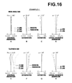
- FIG. 16 illustrates various types of aberrations of the zoom lens of Example 4.
- FIG. 17 illustrates various types of aberrations of the zoom lens of Example 5.
- FIG. 18 illustrates various types of aberrations of the zoom lens of Example 6.
- FIG. 19 illustrates various types of aberrations of the zoom lens of Example 7.
- FIG. 20 illustrates various types of aberrations of the zoom lens of Example 8.
- FIG. 21 illustrates various types of aberrations of the zoom lens of Example 9.
- FIG. 22 illustrates various types of aberrations of the zoom lens of Example 10.
- FIG. 23 illustrates various types of aberrations of the zoom lens of Example 11.
- FIG. 1 is a cross-sectional view of an image pickup apparatus of the present invention equipped with a zoom lens of the present invention, illustrating a schematic configuration thereof. Note that FIG. 1 illustrates an optical path passing the optical axis and an optical path passing outside the optical axis.
- FIG. 1 commonly illustrates an image pickup apparatus 300 A according to a first embodiment equipped with a zoom lens 100 A according to a first embodiment of the present invention, an image pickup apparatus 300 B according to a second embodiment equipped with a zoom lens 100 B according to a second embodiment of the present invention, and an image pickup apparatus 300 C according to a third embodiment equipped with a zoom lens 100 C according to a third embodiment of the present invention.
- the image pickup apparatus 300 A includes the zoom lens 100 A and an image sensor 200 having an imaging plane 210 on which a large number of light receiving pixels are disposed for capturing an optical image 1 K of a subject 1 formed through the zoom lens 100 A.
- the image pickup apparatus 300 B includes the zoom lens 100 B and the image sensor 200 having the imaging plane 210 on which a large number of light receiving pixels are disposed for capturing an optical image 1 K of a subject 1 formed through the zoom lens 100 B.
- the image pickup apparatus 300 C includes the zoom lens 100 C and the image sensor 200 having the imaging plane 210 on which a large number of light receiving pixels are disposed for capturing an optical image 1 K of a subject 1 formed through the zoom lens 100 C.
- zoom lens 100 A according to the first embodiment, zoom lens 100 B according to the second embodiment, and zoom lens 100 C according to the third embodiment are different in configuration.
- an embodiment that satisfies all of the configurations according to the first to third embodiments will be described first followed by each individual embodiment.
- a zoom lens according to an embodiment that satisfies all of the configurations of the respective embodiments and an image pickup apparatus equipped with the zoom lens will now be described.
- the zoom lens that satisfies all of the configurations of the zoom lenses 100 A, 100 B, and 100 C according to the first to third embodiments of the present invention is referred to as the “zoom lens 100 ”.
- the image pickup apparatus that satisfies all of the configurations of the image pickup apparatuses 300 A, 300 B, and 300 C according to the first to third embodiments is referred to as the “image pickup apparatus 300 ”.
- FIG. 1 also illustrates the zoom lens 100 in addition to zoom lenses 100 A, 100 B, and 100 C.
- FIG. 1 also illustrates the image pickup apparatus 300 in addition to image pickup apparatuses 300 A, 300 B, and 300 C.
- the image pickup apparatus 300 shown in FIG. 1 includes the zoom lens 100 and the image sensor 200 having the imaging plane 210 on which a large number of light receiving pixels are disposed for capturing the optical image 1K of the subject 1 formed on the imaging plane 210 through the zoom lens 100 .
- the zoom lens 100 includes a first lens group G 1 which has a positive power and is fixed at the time of zooming, a second lens group G 2 which has a negative power and is moved along an optical axis Z 1 at the time of zooming, an aperture stop St, a third lens group G 3 which has a positive power and is fixed at the time of zooming, and a fourth lens group G 4 which is moved along the optical axis Z 1 at the time of zooming to correct a change in image plane position arising from the zooming for focusing, disposed in this order from the object side.
- the zoom lens 100 may further include a filter Lf.
- the filter Lf is a parallel plate filter for blocking unnecessary light to be incident on the imaging plane 210 , and a filter having a function of low-pass filter or of infrared light cut filter may be employed.
- the first lens group G 1 is composed of a first group first lens L 11 having a negative power, a first group second lens L 12 having a positive power, a first group third lens L 13 having a positive power, and a first group fourth lens L 14 having a positive power, disposed in this order from the object side.
- the second lens group G 2 is composed of a second group first lens L 21 having a negative power, a second group second lens L 22 having a negative power, a second group third lens L 23 having a positive power, and a second group fourth lens L 24 having a positive or negative power with at least one surface being aspheric, disposed in this order from the object side. Note that the second group second lens L 22 and the second group third lens L 23 are cemented.
- the second group fourth lens L 24 is a plastic lens with an object side surface being aspheric and formed such that the intersection between a vertical line drawn to the optical axis Z 1 from the outermost edge of the effective area, which is the position most remote from the optical axis Z 1 within the effective area of the aspheric surface, and the optical axis Z 1 locates on the image plane side of the intersection between the aspheric surface and optical axis Z 1 .
- the third lens group G 3 is composed of a third group first lens L 31 having a positive power with at least one surface being aspheric and a third group second lens L 32 having a negative power.
- the zoom lens 100 satisfies conditional expressions to (M).
- conditional expression (A): 0.62 ⁇ TL/ft ⁇ 0.88 corresponds to the conditional expressions (1), (3), and (12) described above.
- conditional expression (B): 30 ⁇ d 21 ⁇ 48 corresponds to the conditional expressions (2), (7), and (9) described above.
- conditional expression (C): 4.2 ⁇ f 3 /fw ⁇ 8.0 corresponds to the conditional expressions (4) and (11) described above.
- conditional expression (D): 0.17 ⁇ M 2 /ft ⁇ 0.32 corresponds to the conditional expressions (5) and (10) described above.
- conditional expression (E): 17 ⁇ d 11 ⁇ 27 corresponds to the conditional expressions (6) and (8) described above.
- corresponds to the conditional expression (13) described above.
- conditional expression (G): 1.70 ⁇ Nd 14 corresponds to the conditional expression (14) described above.
- conditional expression (H): 42 ⁇ d 14 ⁇ 58 corresponds to the conditional expression (15) described above.
- conditional expression (I): 75 ⁇ d 1 m corresponds to the conditional expression (16) described above.
- conditional expression (J): 0.25 ⁇ f 1 /ft ⁇ 0.50 corresponds to the conditional expression (17) described above.
- conditional expression (K): 1.89 ⁇ Nd 22 corresponds to the conditional expression (18) described above.
- /(fw ⁇ ft) 1/2 ⁇ 0.38 corresponds to the conditional expression (19) described above.
- conditional expression (M): 1.30 ⁇ fw/IH ⁇ 1.75 corresponds to the conditional expression (20) described above.
- ft a focal length of the overall lens system at a telephoto end
- TL a distance from the object side surface of the first group first lens to the image forming plane on the optical axis
- ⁇ d 21 an Abbe number of the second group first lens with respect to d-line;
- f 3 a focal length of the third lens group
- fw a focal length of the overall lens system at a wide angle end
- M 2 an amount of movement of the second lens group at the time of zooming from the wide angle end to the telephoto end;
- ⁇ d 11 an Abbe number of the first group first lens with respect to d-line;
- Nd 14 a refractive index of the first group fourth lens with respect to d-line;
- ⁇ d 14 an Abbe number of the first group fourth lens with respect to d-line;
- ⁇ d 1 m an Abbe number of at least one positive lens in the first lens group with respect to d-line;
- f 1 a focal length of the first lens group
- Nd 22 a refractive index of the second group second lens
- IH a maximum image height
- the maximum image height IH is the distance from the optical axis Z 1 to the farthest point in an optical image formed on the imaging plane, and the “optical image formed on the imaging plane” here is the optical image 1 K of the subject 1 formed on the imaging plane 210 and captured through the zoom lens 100 .
- the overall optical length TL which is the “distance from the object side surface of the first group first lens to the image forming plane on the optical axis” corresponds to the distance from the object side surface of the first group first lens L 11 to the image forming plane (imaging plane 210 ) on the optical axis Z 1 . Note that the distance described above is an actual distance (real distance), not an air equivalent distance.
- conditional expression (A): 0.62 ⁇ TL/ft ⁇ 0.88 specifies the relationship between the overall optical length TL and the focal length of the overall lens system at the telephoto end.
- the zoom lens 100 is configured to fall below the lower limit of the conditional expression (A) for downsizing, correction of field curvature becomes difficult. Further, the power of each lens becomes too strong and becomes sensitive (sensitivity is increased) to the performance degradation due to manufacturing error or assembly error, thereby causing a problem of very high level of difficulty in manufacturing. Still further, this also causes a problem of increased variation in the aberration at the time of zooming and focusing.
- conditional expression (A) is restricted to the range of conditional expression (A′) 0.64 ⁇ TL/ft ⁇ 0.86 and more preferably, to the range of conditional expression (A′′): 0.67 ⁇ TL/ft ⁇ 0.86.
- conditional expression (B) 30 ⁇ d 21 ⁇ 48 specifies the Abbe number of the material of the second group first lens L 21 .
- the zoom lens 100 is configured to fall outside the range of the conditional expression (B), there arises a problem that the correction of lateral chromatic aberration becomes difficult, in particular, the correction of lateral chromatic aberration near the wide angle end in a well-balanced manner with respect to each wavelength.
- the zoom lens 100 is configured to exceed the upper limit of the conditional expression (B)
- the refractive index is generally reduced as the value of ⁇ d 21 is increased beyond the upper limit of the conditional expression (B). If trying to implement downsizing by applying such a material to the second group first lens L 21 and giving a strong power thereto, the curvature of the lens becomes large, the thickness of the overall second lens group G 2 is increased, and there arises a problem that the amount of variation in aberration becomes large.
- conditional expression (B) is restricted to the range of conditional expression (B′): 30 ⁇ d 21 ⁇ 46.
- conditional expression (C) 4.2 ⁇ f 3 /fw ⁇ 8.0 described above specifies the relationship between the focal length of the third lens group G 3 and the focal length of the overall lens system at the wide angle end.
- the zoom lens 100 is configured to exceed the upper limit of the conditional expression (C)
- the power of the third lens group G 3 becomes weak which is advantageous for the aberration correction but disadvantageous for downsizing since the overall length of the lens becomes long.
- an excessive increase in the power of the fourth lens group G 4 causes a problem that the variation in aberration at the time of zooming becomes large. Further, the light incident height on the fourth lens group G 4 becomes large, thereby causing a problem that the size of the overall lens system is increased.
- conditional expression (C) is restricted to the range of conditional expression (C′) 4.3 ⁇ f 3 /fw ⁇ 7.8.
- conditional expression (D): 0.17 ⁇ M 2 /ft ⁇ 0.32 described above specifies the relationship between the amount of movement of the second lens group G 2 at the time of zooming from the wide angle end to the telephoto end and the focal length of the overall lens system at the telephoto end.
- the zoom lens 100 is configured to fall below the lower limit of the conditional expression (D)
- the power of the second lens group G 2 becomes strong and the amount of movement of the second lens group G 2 is reduced. But, there arises a problem that the correction of field curvature becomes difficult.
- conditional expression (D) is restricted to the range of conditional expression (D′) 0.18 ⁇ M 2 /ft ⁇ 0.28.
- conditional expression (E): 17 ⁇ d 11 ⁇ 27 described above specifies the Abbe number of the first group first lens L 11 .
- the thickness of the lens may be reduced. But, this causes a problem that the chromatic aberration, in particular, short wavelength axial chromatic aberration near the telephoto end becomes large.
- the zoom lens 100 is configured to exceed the upper limit of the conditional expression (E)
- the curvatures of the first group first lens L 11 and first group second lens L 12 become large, and the central lens thickness is increased for ensuring a required edge thickness, thereby causing a problem of an increased size of the first lens group G 1 .
- the Petzval sum is increased in the negative direction.
- conditional expression (E) is restricted to the range of conditional expression (E′): 18 ⁇ d 11 ⁇ 26, and more preferably, to the range of conditional expression (E′′): 19 ⁇ d 11 ⁇ 25.
- specifies the relationship between the focal length of the second group fourth lens L 24 and the focal length of the second lens group G 2 .
- the zoom lens 100 is configured to satisfy the conditional expression (F), the variations in the performance and optical characteristics due to temperature change may be minimized even in the case where the second group fourth lens L 24 is formed of a plastic.
- conditional expression (G): 1.70 ⁇ Nd 14 described above specifies the refractive index of the first group fourth lens.
- the zoom lens 100 is configured to fall below the lower limit of the conditional expression (G), there arises a problem that the spherical aberration at the telephoto end is excessively corrected.
- conditional expression (G) is restricted to the range of conditional expression (G′): 1.71 ⁇ Nd 14 .
- conditional expression (H): 42 ⁇ d 14 ⁇ 58 described above specifies the Abbe number of the first group fourth lens L 14 .
- the zoom lens 100 is configured to fall outside the range of the conditional expression (H), the correction of axial chromatic aberration near the telephoto end becomes difficult. Further, this causes a problem that maintaining well-balance with the lateral chromatic aberration near the wide angle end becomes difficult.
- conditional expression (H) is restricted to the range of conditional expression (H′): 42 ⁇ d 14 ⁇ 56.
- conditional expression (I): 75 ⁇ d 1 m described above specifies the Abbe number of a positive lens disposed in the first lens group G 1 .
- the zoom lens 100 is configured to fall below the lower limit of the conditional expression (I), for example, configured such that all of the three positive lenses disposed in the first lens group G 1 (first group second lens L 12 , first group third lens L 13 , and first group fourth lens L 14 ) fall below the lower limit of the conditional expression (I), there arises a problem that axial chromatic aberration near the telephoto end becomes too large.
- conditional expression (I) is restricted to the range of conditional expression (I′): 78 ⁇ d 1 m.
- conditional expression (J): 0.25 ⁇ f 1 /ft ⁇ 0.50 described above specifies the relationship between the focal length of the first lens group G 1 and focal length of the overall lens system at the telephoto end.
- the zoom lens 100 is configured to fall below the lower limit of the conditional expression (J), an excessive burden falls on the first lens group G 1 , thereby causing a problem that the correction of chromatic aberration and spherical aberration near the telephoto end becomes difficult, though advantageous for downsizing.
- conditional expression (J) is restricted to the range of conditional expression (J′): 0.28 ⁇ f 1 /ft ⁇ 0.45.
- conditional expression (K): 1.89 ⁇ Nd 22 described above specifies the refractive index of the second group second lens L 22 .
- the thickness of the second lens group G 2 may be reduced.
- conditional expression (K) is restricted to the range of conditional expression (K′) 1.89 ⁇ Nd 22 ⁇ 1.95. If the zoom lens 100 is configured to exceed the upper limit of the conditional expression (K′), dispersion of, for example, the second group second lens L 22 is increased and the correction of lateral chromatic aberration near the wide angle end may become difficult.
- /(fw ⁇ ft) 1/2 ⁇ 0.38 described above specifies the relationship between the focal length of the second lens group G 2 and focal lengths of the overall lens system at the wide angle end and telephoto end.
- the zoom lens 100 is configured to fall below the lower limit of the conditional expression (L), the power of the second lens group G 2 becomes strong and the amount of movement of the second lens group G 2 at the time of zooming is reduced. But, there arises a problem that the correction of field curvature becomes difficult.
- conditional expression (L) is restricted to the range of conditional expression (L′): 0.26 ⁇
- conditional expression (M): 1.30 ⁇ fw/IH ⁇ 1.75 described above specifies the relationship between the focal length at the wide angle end and maximum image height.
- conditional expression (M) is restricted to the range of conditional expression (M′): 1.35 ⁇ fw/IH ⁇ 1.70.
- the zoom lens 100 A includes a first lens group G 1 which has a positive power and is fixed at the time of zooming, a second lens group G 2 which has a negative power and is moved along an optical axis Z 1 at the time of zooming, an aperture stop St, a third lens group G 3 which has a positive power and is fixed at the time of zooming, a fourth lens group G 4 which is moved along the optical axis Z 1 at the time of zooming to correct a change in image plane position arising from the zooming for focusing, and a filter Lf, disposed in this order from the object side.
- the first lens group G 1 is composed of a first group first lens L 11 having a negative power, a first group second lens L 12 having a positive power, a first group third lens L 13 having a positive power, and a first group fourth lens L 14 having a positive power, disposed in this order from the object side.
- the second lens group G 2 is composed of a second group first lens L 21 having a negative power, a second group second lens L 22 having a negative power, a second group third lens L 23 having a positive power, and a second group fourth lens L 24 having a positive or negative power with at least one surface being aspheric, disposed in this order from the object side.
- the zoom lens 100 A is configured to simultaneously satisfy the conditional expression (A) and conditional expression (B) described above.
- the configuration described above is the essential configuration of the zoom lens 100 A.
- the zoom lens 100 A satisfies the conditional expression (E) described above and more preferably, the conditional expression (E′) described above.
- the zoom lens 100 A satisfies the conditional expression (D) described above and more preferably, the conditional expression (D′) described above.
- the zoom lens 100 A satisfies the conditional expression (C) described above and more preferably, the conditional expression (C′) described above.
- the third lens group G 3 is composed of a third group first lens L 31 having a positive power with at least one surface being aspheric and a third group second lens L 32 having a negative power.
- the second lens group G 2 includes a second group fourth lens L 24 with at least one surface being aspheric disposed on the imaging surface side of the second group third lens L 23 .
- the second lens group G 2 includes the second group fourth lens L 24 with at least one surface being aspheric disposed on the image plane side of the second group third lens L 23
- an object side surface is aspheric and an intersection between a vertical line drawn to the optical axis Z 1 from an outermost edge of an effective area of the aspheric surface and the optical axis Z 1 locates on the image plane side of an intersection between the aspheric surface and optical axis Z 1 .
- the second group fourth lens L 24 is a plastic lens.
- the zoom lens 100 A satisfies the conditional expression (F) described above and more preferably, the conditional expression) (F′) described above.
- the zoom lens 100 A satisfies the conditional expression (G) and conditional expression (H) described above at the same time, and more preferably, the conditional expression (G′) and conditional expression (H′) described above at the same time.
- the zoom lens 100 A satisfies the conditional expression (I) described above and more preferably, the conditional expression (I′) described above.
- the zoom lens 100 A satisfies the conditional expression (J) described above and more preferably, the conditional expression (J′) described above.
- the second group second lens L 22 and second group third lens L 23 in the second lens group G 2 are cemented and the second lens group G 2 satisfies the conditional expression (K) described above and more preferably, the conditional expression (K′) described above.
- the zoom lens 100 A satisfies the conditional expression (L) described above and more preferably, the conditional expression (L′) described above.
- the zoom lens 100 A satisfies the conditional expression (M) described above and more preferably, the conditional expression (M′) described above.
- the zoom lens 100 B includes a first lens group G 1 which has a positive power and is fixed at the time of zooming, a second lens group G 2 which has a negative power and is moved along an optical axis Z 1 at the time of zooming, an aperture stop St, a third lens group G 3 which has a positive power and is fixed at the time of zooming, a fourth lens group G 4 which is moved along the optical axis Z 1 at the time of zooming to correct a change in image plane position arising from the zooming for focusing, and a filter Lf, disposed in this order from the object side.
- the first lens group G 1 is composed of a first group first lens L 11 having a negative power, a first group second lens L 12 having a positive power, a first group third lens L 13 having a positive power, and a first group fourth lens L 14 having a positive power, disposed in this order from the object side.
- the second lens group G 2 is composed of a second group first lens L 21 having a negative power, a second group second lens L 22 having a negative power, and a second group third lens L 23 having a positive power disposed, in this order from the object side.
- the third lens group G 3 is composed of a third group first lens L 31 having a positive power with at least one surface being aspheric and a third group second lens L 32 having a negative power.
- the zoom lens 100 B is configured to satisfy the conditional expression (A) and conditional expression (B) described above at the same time.
- the configuration described above is the essential configuration of the zoom lens 100 B.
- the zoom lens 100 B satisfies the conditional expression (E) described above and more preferably, the conditional expression (E′) described above.
- the zoom lens 100 B satisfies the conditional expression (B) described above and more preferably, the conditional expression (B′) described above.
- the zoom lens 100 B satisfies the conditional expression (D) described above and more preferably, the conditional expression (D′) described above.
- the third lens group G 3 is composed of a third group first lens L 31 having a positive power with at least one surface being aspheric and a third group second lens L 32 having a negative power.
- the second lens group G 2 includes a second group fourth lens L 24 with at least one surface being aspheric on the imaging surface side of the second group third lens L 23 .
- an object side surface of the fourth lens L 24 is aspheric and the intersection between the vertical line drawn to the optical axis Z 1 from the outermost edge of the effective area of the aspheric surface and the optical axis Z 1 locates on the image plane side of the intersection between the aspheric surface and optical axis Z 1 .
- the second group fourth lens L 24 is a plastic lens.
- the zoom lens 100 B satisfies the conditional expression (F) described above and more preferably, the conditional expression (F′) described above.
- the zoom lens 100 B satisfies the conditional expression (G) and conditional expression (H) described above at the same time and more preferably, the conditional expression (G′) and conditional expression (H′) described above at the same time.
- the zoom lens 100 B satisfies the conditional expression (I) described above and more preferably, the conditional expression (I′) described above.
- the zoom lens 100 B satisfies the conditional expression (J) described above and more preferably, the conditional expression (J′) described above.
- the second group second lens L 22 and second group third lens L 23 in the second lens group G 2 are cemented and the second lens group G 2 satisfies the conditional expression (K) described above and more preferably, the conditional expression (K′) described above.
- the zoom lens 100 B satisfies the conditional expression (L) described above and more preferably, the conditional expression (L′) described above.
- the zoom lens 100 B satisfies the conditional expression (M) described above and more preferably, the conditional expression (M′) described above.
- the zoom lens 100 C includes a first lens group G 1 which has a positive power and is fixed at the time of zooming, a second lens group G 2 which has a negative power and is moved along an optical axis Z 1 at the time of zooming, an aperture stop St, a third lens group G 3 which has a positive power and is fixed at the time of zooming, a fourth lens group G 4 which is moved along the optical axis Z 1 at the time of zooming to correct a change in image plane position arising from the zooming for focusing, and a filter Lf, disposed in this order from the object side.
- the first lens group G 1 is composed of a first group first lens L 11 having a negative power, a first group second lens L 12 having a positive power, a first group third lens L 13 having a positive power, and a first group fourth lens L 14 having a positive power, disposed in this order from the object side.
- the second lens group G 2 is composed of a second group first lens L 21 having a negative power, a second group second lens L 22 having a negative power, and a second group third lens L 23 having a positive power, disposed in this order from the object side.
- the zoom lens 100 C is configured to satisfy the conditional expression (B), conditional expression (D), and conditional expression (E) described above at the same time.
- the configuration described above is the essential configuration of the zoom lens 100 C.
- the zoom lens 100 C satisfies the conditional expression (C) described above and more preferably, the conditional expression (C′) described above.
- the zoom lens 100 C satisfies the conditional expression (A) described above and more preferably, the conditional expression (A′) described above.
- the third lens group G 3 is composed of a third group first lens L 31 having a positive power with at least one surface being aspheric and a third group second lens L 32 having a negative power.
- the second lens group G 2 includes a second group fourth lens L 24 with at least one surface being aspheric on the imaging surface side of the second group third lens L 23 .
- an object side surface of the fourth lens L 24 is aspheric and the intersection between the vertical line drawn to the optical axis Z 1 from the outermost edge of the effective area of the aspheric surface and the optical axis Z 1 locates on the image plane side of the intersection between the aspheric surface and optical axis Z 1 .
- the second group fourth lens L 24 is a plastic lens.
- the zoom lens 100 C satisfies the conditional expression (F) described above and more preferably, the conditional expression (F′) described above.
- the zoom lens 100 C satisfies the conditional expression (G) and conditional expression (H) described above at the same time and more preferably, the conditional expression (G′) and conditional expression (H′) described above at the same time.
- the zoom lens 100 C satisfies the conditional expression (I) described above and more preferably, the conditional expression (I′) described above.
- the zoom lens 100 C satisfies the conditional expression (J) described above and more preferably, the conditional expression (J′) described above.
- the second group second lens L 22 and second group third lens L 23 in the second lens group G 2 are cemented and the second lens group G 2 satisfies the conditional expression (K) described above and more preferably, the conditional expression (K′) described above.
- the zoom lens 100 C satisfies the conditional expression (L) described above and more preferably, the conditional expression (L′) described above.
- the zoom lens 100 C satisfies the conditional expression (M) described above and more preferably, the conditional expression (M′) described above.
- FIGS. 2 to 12 are cross-sectional views of zoom lenses of Examples 1 to 11, illustrating schematic configurations thereof. Each drawing comparatively illustrates the state in which the zoom is set to a wide angle end and the state in which it is set to a telephoto end.
- the drawing indicated by the symbol (W) on the upper side of each of FIGS. 2 to 12 represents the state in which the zoom is set to the wide angle end while the drawing indicated by the symbol (T) on the lower side of each of FIGS. 2 to 12 represents the state in which the zoom is set to the telephoto end.
- FIGS. 2 to 12 Symbols in FIGS. 2 to 12 corresponding to those in FIG. 1 illustrating the zoom lens 100 represent the corresponding elements.
- Examples that satisfy the essential configuration of the zoom lens 100 A of the first embodiment are Examples 1 to 7 and Examples 9 to 11, i.e., Examples 1 to 11 except for Example 8.
- Examples that satisfy the essential configuration of the zoom lens 100 B of the second embodiment are also Examples 1 to 7 and Examples 9 to 11, i.e., Examples 1 to 11 except for Example 8.
- Examples that satisfy the essential configuration of the zoom lens 100 C of the third embodiment are Examples 1 to 11 (all Examples).
- L 11 , L 12 , - - - are those that indicate lenses in each lens group and correspond to the order of lenses arranged from the object side.
- Tables 1 to 11 illustrate basic data of zoom lenses of Examples 1 to 11.
- lens data are shown on the upper left (indicated by the symbol (a) in the drawing) while each coefficient of the aspheric surface expression representing the lens surface shape (aspheric surface shape) is shown on the upper right (indicated by the symbol (b) in the drawing).
- f is the focal length (in mm) of the overall lens system
- Fno. is the value of F number
- 2 ⁇ is the value of total field angle
- D 7 , D 14 , D 19 , D 25 , and the like are values of the surface distance between each lens group.
- the surface number of the optical member such as a lens or the like
- the filter Lf is formed of two parallel plates.
- An asterisk * is attached to the surface number for an aspheric lens surface.
- radius of curvature of an aspheric surface indicated by the * mark attached to the surface number thereof is the paraxial radius of curvature.
- the radius of curvature and surface distance are indicated in rum, and the radius of curvature is indicated as positive if it is convex to the object side and as negative if it is convex to the image side.
- Each aspheric surface is defined by the aspheric surface expression given below:
- Table 12 indicates values calculated by formulas described in inequality expressions of the conditional expressions (A) to (M) for each zoom lens of Examples 1 to 11.
- FIGS. 13 to 23 show various aberrations of zoom lenses of Examples 1 to 11. Each drawing illustrates aberrations with respect to the wavelengths corresponding to the d-line, g-line, and C-line respectively.
- the aberration diagrams corresponding to the symbols A to D in each of FIGS. 13 to 23 illustrate aberrations at the wide angle end, in which A is spherical aberration, B is astigmatism, C is distortion, and D is lateral chromatic aberration.
- the aberration diagrams corresponding to the symbols E to H in each drawing illustrate aberrations at the telephoto end, in which E is spherical aberration, F is astigmatism, G is distortion, and H is lateral chromatic aberration.
- Each distortion diagram illustrates a deviation from an ideal image height obtained by f ⁇ tan ⁇ , where f is a focal length of the overall lens system and ⁇ is a half angle of view (treated as a variable, 0 ⁇ ).
- the zoom lenses of the present invention may form a high quality optical image even though they are compact and have a high zoom ratio.
Landscapes
- Physics & Mathematics (AREA)
- General Physics & Mathematics (AREA)
- Optics & Photonics (AREA)
- Nonlinear Science (AREA)
- Lenses (AREA)
Applications Claiming Priority (3)
| Application Number | Priority Date | Filing Date | Title |
|---|---|---|---|
| JP2010-228161 | 2010-10-08 | ||
| JP2010228161 | 2010-10-08 | ||
| PCT/JP2011/005622 WO2012046449A1 (ja) | 2010-10-08 | 2011-10-05 | ズームレンズおよび撮像装置 |
Related Parent Applications (1)
| Application Number | Title | Priority Date | Filing Date |
|---|---|---|---|
| PCT/JP2011/005622 Continuation WO2012046449A1 (ja) | 2010-10-08 | 2011-10-05 | ズームレンズおよび撮像装置 |
Publications (2)
| Publication Number | Publication Date |
|---|---|
| US20130215317A1 US20130215317A1 (en) | 2013-08-22 |
| US9069155B2 true US9069155B2 (en) | 2015-06-30 |
Family
ID=45927454
Family Applications (1)
| Application Number | Title | Priority Date | Filing Date |
|---|---|---|---|
| US13/858,430 Expired - Fee Related US9069155B2 (en) | 2010-10-08 | 2013-04-08 | Zoom lens and image pickup apparatus |
Country Status (4)
| Country | Link |
|---|---|
| US (1) | US9069155B2 (ja) |
| JP (1) | JP5718351B2 (ja) |
| CN (1) | CN103154799B (ja) |
| WO (1) | WO2012046449A1 (ja) |
Families Citing this family (10)
| Publication number | Priority date | Publication date | Assignee | Title |
|---|---|---|---|---|
| KR101776704B1 (ko) * | 2012-08-03 | 2017-09-08 | 한화테크윈 주식회사 | 줌 렌즈계 및 이를 구비한 촬영 장치 |
| JP6268697B2 (ja) * | 2012-10-23 | 2018-01-31 | 株式会社ニコン | 変倍光学系、光学装置、変倍光学系の製造方法 |
| CN108333733B (zh) | 2012-10-23 | 2021-02-26 | 株式会社尼康 | 变倍光学系统和光学装置 |
| JP6153310B2 (ja) * | 2012-10-30 | 2017-06-28 | キヤノン株式会社 | ズームレンズ及びそれを有する撮像装置 |
| JP5907226B2 (ja) * | 2014-09-17 | 2016-04-26 | リコーイメージング株式会社 | ズームレンズ系及びこれを備えた電子撮像装置 |
| CN106842527B (zh) * | 2016-11-10 | 2019-09-03 | 嘉兴中润光学科技有限公司 | 一种变焦距镜头 |
| CN107329239B (zh) * | 2017-08-28 | 2023-04-07 | 深圳市广恩德科技有限公司 | 一种长焦距变焦高清镜头 |
| CN107643591B (zh) * | 2017-11-01 | 2023-08-15 | 河南中光学集团有限公司 | 一种反衰减透雾可见光镜头及实现方法 |
| CN109633875B (zh) * | 2019-01-14 | 2023-10-27 | 广东奥普特科技股份有限公司 | 一种可连续变倍的远心镜头 |
| CN116724264A (zh) * | 2021-04-01 | 2023-09-08 | 深圳市大疆创新科技有限公司 | 摄像头组件、拍摄装置和可移动平台 |
Citations (12)
| Publication number | Priority date | Publication date | Assignee | Title |
|---|---|---|---|---|
| JP2002169087A (ja) | 2000-11-30 | 2002-06-14 | Canon Inc | ズームレンズ及びそれを用いた光学機器 |
| JP2003098434A (ja) | 2001-09-25 | 2003-04-03 | Canon Inc | ズームレンズ及びそれを有する光学機器 |
| JP2007148340A (ja) | 2005-10-31 | 2007-06-14 | Fujinon Corp | ズームレンズ |
| JP2008158418A (ja) | 2006-12-26 | 2008-07-10 | Sony Corp | ズームレンズ及び撮像装置 |
| JP2008164725A (ja) | 2006-12-27 | 2008-07-17 | Sony Corp | ズームレンズ及び撮像装置 |
| US20090201591A1 (en) | 2008-02-12 | 2009-08-13 | Canon Kabushiki Kaisha | Zoom lens system and camera including the same |
| KR20100055950A (ko) | 2008-11-18 | 2010-05-27 | 삼성테크윈 주식회사 | 줌 렌즈 |
| US20100302651A1 (en) | 2009-05-29 | 2010-12-02 | Samsung Techwin Co., Ltd. | Zoom lens |
| US20110157720A1 (en) | 2009-12-25 | 2011-06-30 | Samsung Techwin Co., Ltd. | Zoom lens and photographing apparatus including the same |
| JP2011137875A (ja) | 2009-12-25 | 2011-07-14 | Samsung Techwin Co Ltd | ズームレンズ及び撮像装置 |
| US20130141798A1 (en) * | 2011-12-05 | 2013-06-06 | Samsung Techwin Co., Ltd. | Zoom lens system and photographing apparatus |
| US20130222921A1 (en) * | 2012-02-28 | 2013-08-29 | Tamron Co., Ltd. | Zoom lens |
Family Cites Families (2)
| Publication number | Priority date | Publication date | Assignee | Title |
|---|---|---|---|---|
| US6002529A (en) * | 1993-03-16 | 1999-12-14 | Minolta Co., Ltd. | Zoom lens system |
| JP4366063B2 (ja) * | 2002-09-19 | 2009-11-18 | キヤノン株式会社 | ズームレンズ及びそれを有するカメラ |
-
2011
- 2011-10-05 WO PCT/JP2011/005622 patent/WO2012046449A1/ja active Application Filing
- 2011-10-05 CN CN201180048696.XA patent/CN103154799B/zh not_active Expired - Fee Related
- 2011-10-05 JP JP2012537593A patent/JP5718351B2/ja not_active Expired - Fee Related
-
2013
- 2013-04-08 US US13/858,430 patent/US9069155B2/en not_active Expired - Fee Related
Patent Citations (17)
| Publication number | Priority date | Publication date | Assignee | Title |
|---|---|---|---|---|
| JP2002169087A (ja) | 2000-11-30 | 2002-06-14 | Canon Inc | ズームレンズ及びそれを用いた光学機器 |
| JP2003098434A (ja) | 2001-09-25 | 2003-04-03 | Canon Inc | ズームレンズ及びそれを有する光学機器 |
| JP2007148340A (ja) | 2005-10-31 | 2007-06-14 | Fujinon Corp | ズームレンズ |
| US20070146898A1 (en) | 2005-10-31 | 2007-06-28 | Fujinon Corporation | Zoom lens |
| US20080247054A1 (en) | 2005-10-31 | 2008-10-09 | Ukyo Tomioka | Zoom lens |
| JP2008158418A (ja) | 2006-12-26 | 2008-07-10 | Sony Corp | ズームレンズ及び撮像装置 |
| JP2008164725A (ja) | 2006-12-27 | 2008-07-17 | Sony Corp | ズームレンズ及び撮像装置 |
| JP2009192598A (ja) | 2008-02-12 | 2009-08-27 | Canon Inc | ズームレンズ及びそれを有する撮像装置 |
| US20090201591A1 (en) | 2008-02-12 | 2009-08-13 | Canon Kabushiki Kaisha | Zoom lens system and camera including the same |
| KR20100055950A (ko) | 2008-11-18 | 2010-05-27 | 삼성테크윈 주식회사 | 줌 렌즈 |
| US20100302651A1 (en) | 2009-05-29 | 2010-12-02 | Samsung Techwin Co., Ltd. | Zoom lens |
| JP2010277082A (ja) | 2009-05-29 | 2010-12-09 | Samsung Techwin Co Ltd | ズームレンズ |
| US8320053B2 (en) * | 2009-05-29 | 2012-11-27 | Samsung Techwin Co., Ltd. | Zoom lens |
| US20110157720A1 (en) | 2009-12-25 | 2011-06-30 | Samsung Techwin Co., Ltd. | Zoom lens and photographing apparatus including the same |
| JP2011137875A (ja) | 2009-12-25 | 2011-07-14 | Samsung Techwin Co Ltd | ズームレンズ及び撮像装置 |
| US20130141798A1 (en) * | 2011-12-05 | 2013-06-06 | Samsung Techwin Co., Ltd. | Zoom lens system and photographing apparatus |
| US20130222921A1 (en) * | 2012-02-28 | 2013-08-29 | Tamron Co., Ltd. | Zoom lens |
Non-Patent Citations (2)
| Title |
|---|
| Chinese Office Action, dated Oct. 30, 2014, in corresponding Chinese Patent Application No. 201180048696.X. |
| Japanese Office Action, dated Jan. 20, 2015, in corresponding Japanese Patent Application No. 2012-537593, with partial English translation. |
Also Published As
| Publication number | Publication date |
|---|---|
| JP5718351B2 (ja) | 2015-05-13 |
| CN103154799B (zh) | 2015-06-10 |
| WO2012046449A1 (ja) | 2012-04-12 |
| US20130215317A1 (en) | 2013-08-22 |
| CN103154799A (zh) | 2013-06-12 |
| JPWO2012046449A1 (ja) | 2014-02-24 |
Similar Documents
| Publication | Publication Date | Title |
|---|---|---|
| US9069155B2 (en) | Zoom lens and image pickup apparatus | |
| US8670186B2 (en) | Zoom lens and image pickup apparatus | |
| US7280286B2 (en) | Zoom lens system | |
| JP5388446B2 (ja) | 光学系及びそれを有する光学機器 | |
| JP5202004B2 (ja) | 接合レンズ及びそれを有する光学系並びに接合レンズの製造方法 | |
| US8385010B2 (en) | Imaging lens, optical apparatus and method for forming image using this imaging lens | |
| US8134783B2 (en) | Zoom lens system and image pickup apparatus including the zoom lens system | |
| US8149516B2 (en) | Zoom lens with high optical performance throughout entire zoom range and image pickup apparatus having the same | |
| US20130194487A1 (en) | Image pickup optical system and image pickup apparatus having the same | |
| US20110205636A1 (en) | Zoom lens system, optical apparatus and method for manufacturing zoom lens system | |
| JP4829668B2 (ja) | ズームレンズ及びそれを有する撮像装置 | |
| US8941925B2 (en) | Zoom lens system | |
| US8531768B2 (en) | Zoom lens system | |
| US10705317B2 (en) | Zooming imaging optical system | |
| US8553328B2 (en) | Zoom lens system | |
| JP6635250B2 (ja) | 撮像光学系及びそれを有する撮像装置 | |
| US9798123B2 (en) | Zoom lens system | |
| US9645367B2 (en) | Zoom lens system | |
| US9069158B2 (en) | Variable magnification optical system and imaging apparatus | |
| US9581794B2 (en) | Zoom lens system | |
| US20220019063A1 (en) | Zoom optical system, optical apparatus and method for manufacturing the zoom optical system | |
| JP5159941B2 (ja) | ズームレンズ及びそれを有する撮像装置 | |
| JP7423044B2 (ja) | 光学系 | |
| JP6064534B2 (ja) | 結像レンズ、撮像装置、携帯情報端末装置 | |
| JP2009265306A (ja) | ズームレンズ |
Legal Events
| Date | Code | Title | Description |
|---|---|---|---|
| AS | Assignment |
Owner name: FUJIFILM CORPORATION, JAPAN Free format text: ASSIGNMENT OF ASSIGNORS INTEREST;ASSIGNOR:KAWAMURA, DAIKI;REEL/FRAME:030170/0382 Effective date: 20130221 |
|
| STCF | Information on status: patent grant |
Free format text: PATENTED CASE |
|
| FEPP | Fee payment procedure |
Free format text: MAINTENANCE FEE REMINDER MAILED (ORIGINAL EVENT CODE: REM.); ENTITY STATUS OF PATENT OWNER: LARGE ENTITY |
|
| LAPS | Lapse for failure to pay maintenance fees |
Free format text: PATENT EXPIRED FOR FAILURE TO PAY MAINTENANCE FEES (ORIGINAL EVENT CODE: EXP.); ENTITY STATUS OF PATENT OWNER: LARGE ENTITY |
|
| STCH | Information on status: patent discontinuation |
Free format text: PATENT EXPIRED DUE TO NONPAYMENT OF MAINTENANCE FEES UNDER 37 CFR 1.362 |
|
| FP | Expired due to failure to pay maintenance fee |
Effective date: 20190630 |