US9011173B2 - Multi-connected connector - Google Patents
Multi-connected connector Download PDFInfo
- Publication number
- US9011173B2 US9011173B2 US13/883,147 US201213883147A US9011173B2 US 9011173 B2 US9011173 B2 US 9011173B2 US 201213883147 A US201213883147 A US 201213883147A US 9011173 B2 US9011173 B2 US 9011173B2
- Authority
- US
- United States
- Prior art keywords
- connector
- connectors
- fitting
- rear end
- attached
- Prior art date
- Legal status (The legal status is an assumption and is not a legal conclusion. Google has not performed a legal analysis and makes no representation as to the accuracy of the status listed.)
- Active
Links
Images


Classifications
-
- H—ELECTRICITY
- H01—ELECTRIC ELEMENTS
- H01R—ELECTRICALLY-CONDUCTIVE CONNECTIONS; STRUCTURAL ASSOCIATIONS OF A PLURALITY OF MUTUALLY-INSULATED ELECTRICAL CONNECTING ELEMENTS; COUPLING DEVICES; CURRENT COLLECTORS
- H01R13/00—Details of coupling devices of the kinds covered by groups H01R12/70 or H01R24/00 - H01R33/00
- H01R13/46—Bases; Cases
- H01R13/514—Bases; Cases composed as a modular blocks or assembly, i.e. composed of co-operating parts provided with contact members or holding contact members between them
-
- H—ELECTRICITY
- H01—ELECTRIC ELEMENTS
- H01R—ELECTRICALLY-CONDUCTIVE CONNECTIONS; STRUCTURAL ASSOCIATIONS OF A PLURALITY OF MUTUALLY-INSULATED ELECTRICAL CONNECTING ELEMENTS; COUPLING DEVICES; CURRENT COLLECTORS
- H01R13/00—Details of coupling devices of the kinds covered by groups H01R12/70 or H01R24/00 - H01R33/00
- H01R13/46—Bases; Cases
- H01R13/516—Means for holding or embracing insulating body, e.g. casing, hoods
- H01R13/518—Means for holding or embracing insulating body, e.g. casing, hoods for holding or embracing several coupling parts, e.g. frames
-
- H—ELECTRICITY
- H01—ELECTRIC ELEMENTS
- H01R—ELECTRICALLY-CONDUCTIVE CONNECTIONS; STRUCTURAL ASSOCIATIONS OF A PLURALITY OF MUTUALLY-INSULATED ELECTRICAL CONNECTING ELEMENTS; COUPLING DEVICES; CURRENT COLLECTORS
- H01R13/00—Details of coupling devices of the kinds covered by groups H01R12/70 or H01R24/00 - H01R33/00
- H01R13/64—Means for preventing incorrect coupling
- H01R13/641—Means for preventing incorrect coupling by indicating incorrect coupling; by indicating correct or full engagement
Definitions
- the present invention relates to a multi-connected connector that a plurality of first connectors are fitted and attached to a second connector under a state that the plurality of first connectors are arranged in one row in a transverse direction.
- FIG. 6 shows a usual example of a multi-connected connector directly attached to a printed circuit board.
- the multi-connected connector 100 is disclosed in a below-described PTL 1 and includes a plurality of first connectors 110 and a second connector 120 to which the first connectors 110 are fitted and attached.
- the second connector 120 is provided, as shown in the drawing, in a form that a plurality of connector fitting chambers 121 are arranged in a row in a transverse direction. Each of the connector fitting chambers 121 is a part to which the first connector 110 is fitted and attached.
- the second connector 120 is provided with a simultaneous fitting detecting member 130 .
- the simultaneous fitting detecting member 130 is a member that simultaneously pushes in rear ends of the plurality of first connectors 110 temporarily attached to the connector fitting chambers 121 respectively to their normal fitting completed positions.
- the simultaneous fitting detecting member 130 has one end side connected to the second connector 120 so as to freely rotate by a hinge 131 and is pressed respectively to the rear ends of the first connectors 110 by a rotating operation.
- the engaging hook 132 of the simultaneous fitting detecting member 130 is not engaged with the engaging part of the second connector 120 side.
- it can be detected whether or not the first connectors are located in the half inserted state in accordance with that state.
- the multi-connected connector 100 shown in FIG. 6 forms and dimensions of all the plurality of first connectors 110 attached to the second connector 120 are the same.
- the multi-connected connector may include such structures as shown in FIG. 7 and FIG. 8 .
- a multi-connected connector 100 A shown in FIG. 7 and FIG. 8 includes a plurality of first connectors 110 a , 110 b , 110 c and 110 d and a second connector 120 A to which the first connectors 110 a , 110 b , 110 c and 110 d are fitted and attached.
- the second connector 120 A is provided, as shown in the drawing, in a form that a plurality of connector fitting chambers 121 a , 121 b , 121 c and 121 d are arranged in a row in a transverse direction.
- the connector fitting chambers 121 a , 121 b , 121 c and 121 d are respectively parts to which the first connectors 110 a , 110 b , 110 c and 110 d are fitted and attached.
- the plurality of first connectors 110 a , 110 b , 110 c and 110 d are different in their dimension of width due to the difference of the number of accommodated connecting terminals or the forms of terminals.
- a length in a fitting direction is shorter than those of other first connectors 110 a , 110 b and 110 d.
- the butting walls 122 a , 122 b , 122 c and 122 d are positioning parts on which end surfaces of the first connectors 110 a , 110 b , 110 c and 110 d abut to determine fitting completed positions of the first connectors 110 a , 110 b , 110 c and 110 d.
- the above-described butting walls 122 a , 122 b , 122 c and 122 d are arranged in a row in a transverse direction so as to align their positions as shown in FIG. 9 .
- the recessed part of the first connector 110 c whose length in the fitting direction is smaller is more reduced than that in a normal case, or as shown in FIG. 11 , the rear end 110 c is aligned with the positions of the rear ends of the other first connectors 110 a , 110 b and 110 d.
- the present invention has been made in view of these situations and possibility. It is an object of the present invention to provide a multi-connected connector which can simply discriminate whether or not a plurality of first connectors multi-connected to a second connector are located in half inserted states only by an external appearance without using a special member and can reduce a cost by simplifying a structure.
- a multi-connected connector comprises a plurality of first connectors, and a second connector having a plurality of connector fitting chambers arranged in a row in a transverse direction to fit the first connectors, wherein the plurality of first connectors include a connector whose length is different from the other connector of the first connectors in a fitting direction of the first connectors, and positioning parts that determine fitting completed positions of the first connectors are respectively provided in the connector fitting chambers and arranged in accordance with lengths in the fitting direction of the first connectors to be connected so that rear end surfaces of the plurality of first connectors that are normally completely fitted are aligned so as to be flush.
- the rear end surface protrudes more than the positions of the rear end surfaces of other first connectors which are completely inserted to the second connector irrespective of the length of the connector in the fitting direction.
- the presence or absence of the half inserted state can be simply discriminated without using a special member.
- the special member such as the simultaneous fitting detecting member is not used to discriminate whether or not the half inserted state is present, a cost can be reduced by simplifying the structure of the connector.
- the rear end surface protrudes more than the positions of the rear end surfaces of other first connectors which are completely inserted to the second connector irrespective of the length of the connector in the fitting direction.
- the special member such as the simultaneous fitting detecting member is not used to discriminate whether or not the half inserted state is present, a cost can be reduced by simplifying the structure of the connector.
- FIG. 1 is an exploded perspective view of one exemplary embodiment of a multi-connected connector according to the present invention.
- FIG. 2 is a perspective view of an assembled state of the multi-connected connector shown in FIG. 1 .
- FIG. 3 is a horizontally sectional view showing a second connector shown in FIG. 1 and a plurality of first connectors attached to the second connector.
- FIG. 4 is a horizontally sectional view showing a state that the plurality of first connectors are fitted and attached to the second connector shown in FIG. 3 and all the first connectors are located in completely inserted states.
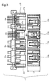
- FIG. 5 is a horizontally sectional view showing a state that the plurality of first connectors are fitted and attached to the second connector shown in FIG. 3 and only the first connector whose length in a fitting direction is shorter is located in a half inserted state.
- FIG. 6 is an exploded perspective view of a usual multi-connected connector.
- FIG. 7 is an exploded perspective view of another usual multi-connected connector.
- FIG. 8 is a perspective view of an assembled state of the multi-connected connector shown in FIG. 7 .
- FIG. 9 is a horizontally sectional view showing a second connector shown in FIG. 7 and a plurality of first connectors attached to the second connector.
- FIG. 10 is a horizontally sectional view showing a state that the plurality of first connectors are fitted and attached to the second connector shown in FIG. 9 and all the first connectors are located in completely inserted states.
- FIG. 11 is a horizontally sectional view showing a state that the plurality of first connectors are fitted and attached to the second connector shown in FIG. 9 and only the first connector whose length in a fitting direction is shorter is located in a half inserted state.
- FIGS. 1 to 5 show one exemplary embodiment of a multi-connected connector according to the present invention.
- FIG. 1 is an exploded perspective view of one exemplary embodiment of the multi-connected connector according to the present invention.
- FIG. 2 is a perspective view of an assembled state of the multi-connected connector shown in FIG. 1 .
- FIG. 3 is a horizontally sectional view showing a second connector shown in FIG. 1 and a plurality of first connectors attached to the second connector.
- FIG. 4 is a horizontally sectional view showing a state that the plurality of first connectors are fitted and attached to the second connector shown in FIG. 3 and all the first connectors are located in completely inserted states.
- FIG. 5 is a horizontally sectional view showing a state that the plurality of first connectors are fitted and attached to the second connector shown in FIG. 3 and only the first connector whose length in a fitting direction is shorter is located in a half inserted state.
- the multi-connected connector 1 of one exemplary embodiment is formed by improving the multi-connected connector 100 A shown in FIG. 7 and FIG. 8 and includes four first connectors 110 a , 110 b , 110 c and 110 d and a second connector 20 to which the four first connectors 110 a , 110 b , 110 c and 110 d are fitted and attached.
- the second connector 20 is provided, as shown in FIG. 1 , in a form that a plurality of connector fitting chambers 21 a , 21 b , 21 c and 21 d are arranged in a row in a transverse direction.
- the connector fitting chambers 21 a , 21 b , 21 c and 21 d are respectively parts to which the first connectors 110 a , 110 b , 110 c and 110 d are fitted and attached.
- the plurality of first connectors 110 a , 110 b , 110 c and 110 d are different in their dimension of width due to the difference of the number of accommodated connecting terminals or the forms of terminals.
- a length in a fitting direction is shorter than those of other first connectors 110 a , 110 b and 110 d .
- the plurality of first connectors attached to the second connector 20 include connectors whose lengths in a fitting direction are different from each other.
- the lengths in the fitting direction are set to L 2 .
- the length in the fitting direction is set to L 3 in the shorter first connector 110 c .
- a difference between the length L 3 and L 2 is L 4 .
- the butting walls 22 a , 22 b , 22 c and 22 d are positioning parts on which end surfaces of the first connectors 110 a , 110 b , 110 c and 110 d abut to determine fitting completed positions of the first connectors 110 a , 110 b , 110 c and 110 d.
- the butting walls 22 a , 22 b , 22 c and 22 d are arranged, as shown in FIG. 4 , in accordance with the lengths in the fitting direction of the first connectors to be connected so that rear end surfaces of the plurality of first connectors 110 a , 110 b , 110 c and 110 d which are normally completely fitted are respectively aligned so as to be flush with a reference surface position H 1 .
- the butting wall 22 c which positions the shorter first connector 110 c is arranged, as shown in FIG. 3 , so as to protrude more to the first connector side by the difference L 4 in length in the fitting direction between the first connector 110 c and other first connectors than other butting walls 22 a , 22 b and 22 d.
- the rear end of the first connector 110 c protrudes more by an insufficient insertion L 5 than the positions (the reference surface position H 1 ) of the rear ends of other first connectors 110 a , 110 b and 110 d .
- the half inserted state of the first connector 110 c can be simply discriminated from an external appearance.
- the rear end surfaces of all the first connectors 110 a , 110 b , 110 c and 110 d are aligned so as to be flush irrespective of the difference in length in the fitting direction of the first connectors 110 a , 110 b , 110 c and 110 d.
- the rear end surface protrudes more than the positions of the rear end surfaces of other first connectors 1 which are completely inserted to the second connector 20 irrespective of the length of the connector in the fitting direction.
- first connectors 110 a , 110 b , 110 c and 110 d arranged in one row in the transverse direction on the second connector 20 when external appearances are merely compared as to whether or not the rear end surface protrudes more than those of other first connectors, the presence or absence of the half inserted state can be simply discriminated without using a special member.
- the special member such as the simultaneous fitting detecting member is not used to discriminate whether or not the half inserted state is present, a cost can be reduced by simplifying the structure of the connector.
- the multi-connected connector of the present invention is not limited to the above-described exemplary embodiment, and a suitable modification and an improvement may be made.
- the number of the first connectors fitted and attached to the second connector is not limited to the above-described exemplary embodiment.
- the present invention may be applied to a case in that a plurality of connectors fitted and attached to the second connector include three or more kinds of connectors having different lengths in a fitting direction.
- positioning parts that determine the fitting completed positions of the first connectors in the connector fitting chambers are not limited to the butting walls shown in the above-described exemplary embodiment.
- a positioning part may include a partly protruding part.
- the rear end surface protrudes more than the positions of the rear end surfaces of other first connectors which are completely inserted to the second connector irrespective of the length of the connector in the fitting direction.
- the presence or absence of the half inserted state can be simply discriminated without using a special member.
Landscapes
- Details Of Connecting Devices For Male And Female Coupling (AREA)
- Connector Housings Or Holding Contact Members (AREA)
Applications Claiming Priority (3)
| Application Number | Priority Date | Filing Date | Title |
|---|---|---|---|
| JP2011009133A JP5647016B2 (ja) | 2011-01-19 | 2011-01-19 | 多連装コネクタ |
| JP2011-009133 | 2011-01-19 | ||
| PCT/JP2012/051583 WO2012099274A1 (en) | 2011-01-19 | 2012-01-19 | Multi-Connected Connector |
Publications (2)
| Publication Number | Publication Date |
|---|---|
| US20130288517A1 US20130288517A1 (en) | 2013-10-31 |
| US9011173B2 true US9011173B2 (en) | 2015-04-21 |
Family
ID=45768271
Family Applications (1)
| Application Number | Title | Priority Date | Filing Date |
|---|---|---|---|
| US13/883,147 Active US9011173B2 (en) | 2011-01-19 | 2012-01-19 | Multi-connected connector |
Country Status (6)
| Country | Link |
|---|---|
| US (1) | US9011173B2 (zh) |
| JP (1) | JP5647016B2 (zh) |
| KR (1) | KR101612167B1 (zh) |
| CN (1) | CN103314485B (zh) |
| DE (1) | DE112012000511B4 (zh) |
| WO (1) | WO2012099274A1 (zh) |
Cited By (4)
| Publication number | Priority date | Publication date | Assignee | Title |
|---|---|---|---|---|
| US20170076894A1 (en) * | 2014-03-14 | 2017-03-16 | Omron Corporation | Electronic device and manufacturing method therefor |
| US20170188479A1 (en) * | 2014-05-06 | 2017-06-29 | Phoenix Contact Gmbh & Co. Kg | Terminal block for an electronic device |
| US20220216641A1 (en) * | 2021-01-07 | 2022-07-07 | Japan Aviation Electronics Industry, Ltd. | Connector |
| US11431140B2 (en) * | 2020-08-05 | 2022-08-30 | Japan Aviation Electronics Industry, Ltd. | Composite connector |
Families Citing this family (2)
| Publication number | Priority date | Publication date | Assignee | Title |
|---|---|---|---|---|
| KR20150098723A (ko) | 2014-02-21 | 2015-08-31 | 현대자동차주식회사 | 자동차용 공용 스위치 장치 |
| JP2024075355A (ja) * | 2022-11-22 | 2024-06-03 | 矢崎総業株式会社 | コネクタ及びコネクタ接続構造 |
Citations (11)
| Publication number | Priority date | Publication date | Assignee | Title |
|---|---|---|---|---|
| US4997386A (en) * | 1989-03-01 | 1991-03-05 | Japan Aviation Electronics Industry Ltd. | Connectors |
| US5454733A (en) | 1993-04-21 | 1995-10-03 | Yazaki Corporation | Divisional multi-pole connector |
| US5545053A (en) * | 1993-01-25 | 1996-08-13 | Yazaki Corporation | Multi-pole connector |
| US5638824A (en) * | 1993-02-25 | 1997-06-17 | Advanced Monitors Holdings Limited | Ultrasonic monitor |
| US5679028A (en) * | 1994-06-17 | 1997-10-21 | Yazaki Corporation | Division-type multi-pole connector |
| US5775953A (en) * | 1995-05-16 | 1998-07-07 | Yazaki Corporation | Low-insertion-force connector assembly |
| US5797757A (en) * | 1995-11-13 | 1998-08-25 | Yazaki Corporation | PCB multi-pole connector |
| US6191672B1 (en) * | 1997-01-28 | 2001-02-20 | Siemens Aktiengesellschaft | Relay socket |
| US6659810B2 (en) * | 2001-06-04 | 2003-12-09 | Yazaki Corporation | Method of assembling multi-pole connector and multi-pole connector |
| EP1662618A1 (en) | 2004-11-30 | 2006-05-31 | Tyco Electronics AMP K.K. | An electrical connector housing, an electrical connector, and a connector assembly. |
| JP2008066122A (ja) | 2006-09-07 | 2008-03-21 | Yazaki Corp | 多連装コネクタ |
Family Cites Families (4)
| Publication number | Priority date | Publication date | Assignee | Title |
|---|---|---|---|---|
| JP2671729B2 (ja) * | 1992-09-29 | 1997-10-29 | 住友電装株式会社 | コネクタ装置 |
| JPH11162571A (ja) * | 1997-12-01 | 1999-06-18 | Sumitomo Wiring Syst Ltd | 嵌合状態確認治具 |
| JP2000091035A (ja) * | 1998-09-10 | 2000-03-31 | Sumitomo Wiring Syst Ltd | 電気接続箱 |
| JP2011009133A (ja) | 2009-06-29 | 2011-01-13 | Toyota Motor Corp | 燃料電池システムの制御装置 |
-
2011
- 2011-01-19 JP JP2011009133A patent/JP5647016B2/ja active Active
-
2012
- 2012-01-19 DE DE112012000511.2T patent/DE112012000511B4/de active Active
- 2012-01-19 KR KR1020137018930A patent/KR101612167B1/ko active IP Right Grant
- 2012-01-19 CN CN201280005781.2A patent/CN103314485B/zh active Active
- 2012-01-19 WO PCT/JP2012/051583 patent/WO2012099274A1/en active Application Filing
- 2012-01-19 US US13/883,147 patent/US9011173B2/en active Active
Patent Citations (12)
| Publication number | Priority date | Publication date | Assignee | Title |
|---|---|---|---|---|
| US4997386A (en) * | 1989-03-01 | 1991-03-05 | Japan Aviation Electronics Industry Ltd. | Connectors |
| US5545053A (en) * | 1993-01-25 | 1996-08-13 | Yazaki Corporation | Multi-pole connector |
| US5638824A (en) * | 1993-02-25 | 1997-06-17 | Advanced Monitors Holdings Limited | Ultrasonic monitor |
| US5454733A (en) | 1993-04-21 | 1995-10-03 | Yazaki Corporation | Divisional multi-pole connector |
| JP2799444B2 (ja) | 1993-04-21 | 1998-09-17 | 矢崎総業株式会社 | 分割多極コネクタ |
| US5679028A (en) * | 1994-06-17 | 1997-10-21 | Yazaki Corporation | Division-type multi-pole connector |
| US5775953A (en) * | 1995-05-16 | 1998-07-07 | Yazaki Corporation | Low-insertion-force connector assembly |
| US5797757A (en) * | 1995-11-13 | 1998-08-25 | Yazaki Corporation | PCB multi-pole connector |
| US6191672B1 (en) * | 1997-01-28 | 2001-02-20 | Siemens Aktiengesellschaft | Relay socket |
| US6659810B2 (en) * | 2001-06-04 | 2003-12-09 | Yazaki Corporation | Method of assembling multi-pole connector and multi-pole connector |
| EP1662618A1 (en) | 2004-11-30 | 2006-05-31 | Tyco Electronics AMP K.K. | An electrical connector housing, an electrical connector, and a connector assembly. |
| JP2008066122A (ja) | 2006-09-07 | 2008-03-21 | Yazaki Corp | 多連装コネクタ |
Non-Patent Citations (4)
| Title |
|---|
| Chinese Office Action for the related Chinese Patent Application No. 201280005781.2 dated Feb. 2, 2015. |
| International Search Report and Written Opinion of the International Search Report for PCT/JP2012/051583 dated Apr. 25, 2012. |
| Korean Office Action for the related Korean Patent Application No. 10-2013-7018930 dated Feb. 9, 2015. |
| Korean Office Action for the related Korean Patent Application No. 10-2013-7018930 dated Jun. 25, 2014. |
Cited By (7)
| Publication number | Priority date | Publication date | Assignee | Title |
|---|---|---|---|---|
| US20170076894A1 (en) * | 2014-03-14 | 2017-03-16 | Omron Corporation | Electronic device and manufacturing method therefor |
| US9966213B2 (en) * | 2014-03-14 | 2018-05-08 | Omron Corporation | Electronic device and manufacturing method therefor |
| US20170188479A1 (en) * | 2014-05-06 | 2017-06-29 | Phoenix Contact Gmbh & Co. Kg | Terminal block for an electronic device |
| US10178790B2 (en) * | 2014-05-06 | 2019-01-08 | Phoenix Contact Gmbh & Co. Kg | Terminal block for an electronic device |
| US11431140B2 (en) * | 2020-08-05 | 2022-08-30 | Japan Aviation Electronics Industry, Ltd. | Composite connector |
| US20220216641A1 (en) * | 2021-01-07 | 2022-07-07 | Japan Aviation Electronics Industry, Ltd. | Connector |
| US11901665B2 (en) * | 2021-01-07 | 2024-02-13 | Japan Aviation Electronics Industry, Ltd. | Connector including external housing and plural internal housings |
Also Published As
| Publication number | Publication date |
|---|---|
| CN103314485B (zh) | 2016-02-03 |
| KR20130116309A (ko) | 2013-10-23 |
| KR101612167B1 (ko) | 2016-04-12 |
| JP5647016B2 (ja) | 2014-12-24 |
| DE112012000511T5 (de) | 2013-10-24 |
| US20130288517A1 (en) | 2013-10-31 |
| JP2012151008A (ja) | 2012-08-09 |
| WO2012099274A1 (en) | 2012-07-26 |
| CN103314485A (zh) | 2013-09-18 |
| DE112012000511B4 (de) | 2021-04-01 |
Similar Documents
| Publication | Publication Date | Title |
|---|---|---|
| US9011173B2 (en) | Multi-connected connector | |
| US9553409B2 (en) | Electrical tongue connector with good shielding and improved contact performance | |
| US8092262B1 (en) | Eye-of-the needle pin of an electrical contact | |
| US10498068B2 (en) | Connector with stacked sub-housings | |
| JP2014032804A (ja) | コネクタ | |
| JP2007095360A (ja) | 合体コネクタ | |
| WO2007016706A3 (en) | Board-to-board connector for mounting on a circuit board | |
| EP3002831A1 (en) | Connector | |
| US10498077B2 (en) | Power connector and power connector device | |
| US20170250489A1 (en) | Connector | |
| WO2015094120A1 (en) | Electrical cable connector and connector assembly thereof | |
| US7367812B2 (en) | Circuit board and electrical assembly using the same | |
| US6604952B2 (en) | Printed circuit board connector | |
| WO2011040419A1 (ja) | 基板用コネクタの実装構造 | |
| US10686274B2 (en) | Plug connector having a contact housing, outer housing and securing element | |
| TWI628881B (zh) | Connector device for substrate connection | |
| JP6352676B2 (ja) | コネクタ | |
| JP2008130323A (ja) | コネクタ | |
| US8556663B2 (en) | USB jack and USB plug | |
| JP2012038497A5 (zh) | ||
| JP5009742B2 (ja) | プログラマブルコントローラにおけるバス拡張構造 | |
| US8523613B2 (en) | Electrical connector for broadside coupled or edge coupled mating with mating connector | |
| CN205051085U (zh) | 电连接器组件 | |
| JP2007115538A (ja) | 基板用電気コネクタ取付装置 | |
| JPH1050379A (ja) | 電気コネクタ |
Legal Events
| Date | Code | Title | Description |
|---|---|---|---|
| AS | Assignment |
Owner name: YAZAKI CORPORATION, JAPAN Free format text: ASSIGNMENT OF ASSIGNORS INTEREST;ASSIGNORS:OSADA, TAKESHI;HASEGAWA, TAKUYA;REEL/FRAME:030338/0232 Effective date: 20130501 |
|
| FEPP | Fee payment procedure |
Free format text: PAYOR NUMBER ASSIGNED (ORIGINAL EVENT CODE: ASPN); ENTITY STATUS OF PATENT OWNER: LARGE ENTITY |
|
| STCF | Information on status: patent grant |
Free format text: PATENTED CASE |
|
| MAFP | Maintenance fee payment |
Free format text: PAYMENT OF MAINTENANCE FEE, 4TH YEAR, LARGE ENTITY (ORIGINAL EVENT CODE: M1551); ENTITY STATUS OF PATENT OWNER: LARGE ENTITY Year of fee payment: 4 |
|
| MAFP | Maintenance fee payment |
Free format text: PAYMENT OF MAINTENANCE FEE, 8TH YEAR, LARGE ENTITY (ORIGINAL EVENT CODE: M1552); ENTITY STATUS OF PATENT OWNER: LARGE ENTITY Year of fee payment: 8 |
|
| AS | Assignment |
Owner name: YAZAKI CORPORATION, JAPAN Free format text: CHANGE OF ADDRESS;ASSIGNOR:YAZAKI CORPORATION;REEL/FRAME:063845/0802 Effective date: 20230331 |