US8993172B2 - Li-ion battery and battery active components on metal wire - Google Patents
Li-ion battery and battery active components on metal wire Download PDFInfo
- Publication number
- US8993172B2 US8993172B2 US13/708,137 US201213708137A US8993172B2 US 8993172 B2 US8993172 B2 US 8993172B2 US 201213708137 A US201213708137 A US 201213708137A US 8993172 B2 US8993172 B2 US 8993172B2
- Authority
- US
- United States
- Prior art keywords
- battery
- layer
- wire
- metal wire
- electrode
- Prior art date
- Legal status (The legal status is an assumption and is not a legal conclusion. Google has not performed a legal analysis and makes no representation as to the accuracy of the status listed.)
- Expired - Fee Related, expires
Links
Images


Classifications
-
- H—ELECTRICITY
- H01—ELECTRIC ELEMENTS
- H01M—PROCESSES OR MEANS, e.g. BATTERIES, FOR THE DIRECT CONVERSION OF CHEMICAL ENERGY INTO ELECTRICAL ENERGY
- H01M50/00—Constructional details or processes of manufacture of the non-active parts of electrochemical cells other than fuel cells, e.g. hybrid cells
- H01M50/20—Mountings; Secondary casings or frames; Racks, modules or packs; Suspension devices; Shock absorbers; Transport or carrying devices; Holders
- H01M50/204—Racks, modules or packs for multiple batteries or multiple cells
- H01M50/207—Racks, modules or packs for multiple batteries or multiple cells characterised by their shape
- H01M50/213—Racks, modules or packs for multiple batteries or multiple cells characterised by their shape adapted for cells having curved cross-section, e.g. round or elliptic
-
- H—ELECTRICITY
- H01—ELECTRIC ELEMENTS
- H01M—PROCESSES OR MEANS, e.g. BATTERIES, FOR THE DIRECT CONVERSION OF CHEMICAL ENERGY INTO ELECTRICAL ENERGY
- H01M4/00—Electrodes
- H01M4/02—Electrodes composed of, or comprising, active material
- H01M4/04—Processes of manufacture in general
- H01M4/0402—Methods of deposition of the material
- H01M4/0404—Methods of deposition of the material by coating on electrode collectors
-
- H—ELECTRICITY
- H01—ELECTRIC ELEMENTS
- H01M—PROCESSES OR MEANS, e.g. BATTERIES, FOR THE DIRECT CONVERSION OF CHEMICAL ENERGY INTO ELECTRICAL ENERGY
- H01M10/00—Secondary cells; Manufacture thereof
- H01M10/04—Construction or manufacture in general
-
- H—ELECTRICITY
- H01—ELECTRIC ELEMENTS
- H01M—PROCESSES OR MEANS, e.g. BATTERIES, FOR THE DIRECT CONVERSION OF CHEMICAL ENERGY INTO ELECTRICAL ENERGY
- H01M10/00—Secondary cells; Manufacture thereof
- H01M10/04—Construction or manufacture in general
- H01M10/049—Processes for forming or storing electrodes in the battery container
-
- H—ELECTRICITY
- H01—ELECTRIC ELEMENTS
- H01M—PROCESSES OR MEANS, e.g. BATTERIES, FOR THE DIRECT CONVERSION OF CHEMICAL ENERGY INTO ELECTRICAL ENERGY
- H01M10/00—Secondary cells; Manufacture thereof
- H01M10/05—Accumulators with non-aqueous electrolyte
- H01M10/052—Li-accumulators
- H01M10/0525—Rocking-chair batteries, i.e. batteries with lithium insertion or intercalation in both electrodes; Lithium-ion batteries
-
- H—ELECTRICITY
- H01—ELECTRIC ELEMENTS
- H01M—PROCESSES OR MEANS, e.g. BATTERIES, FOR THE DIRECT CONVERSION OF CHEMICAL ENERGY INTO ELECTRICAL ENERGY
- H01M10/00—Secondary cells; Manufacture thereof
- H01M10/05—Accumulators with non-aqueous electrolyte
- H01M10/058—Construction or manufacture
-
- H—ELECTRICITY
- H01—ELECTRIC ELEMENTS
- H01M—PROCESSES OR MEANS, e.g. BATTERIES, FOR THE DIRECT CONVERSION OF CHEMICAL ENERGY INTO ELECTRICAL ENERGY
- H01M10/00—Secondary cells; Manufacture thereof
- H01M10/05—Accumulators with non-aqueous electrolyte
- H01M10/058—Construction or manufacture
- H01M10/0587—Construction or manufacture of accumulators having only wound construction elements, i.e. wound positive electrodes, wound negative electrodes and wound separators
-
- H01M2/105—
-
- H—ELECTRICITY
- H01—ELECTRIC ELEMENTS
- H01M—PROCESSES OR MEANS, e.g. BATTERIES, FOR THE DIRECT CONVERSION OF CHEMICAL ENERGY INTO ELECTRICAL ENERGY
- H01M4/00—Electrodes
- H01M4/02—Electrodes composed of, or comprising, active material
- H01M4/04—Processes of manufacture in general
- H01M4/0471—Processes of manufacture in general involving thermal treatment, e.g. firing, sintering, backing particulate active material, thermal decomposition, pyrolysis
-
- H—ELECTRICITY
- H01—ELECTRIC ELEMENTS
- H01M—PROCESSES OR MEANS, e.g. BATTERIES, FOR THE DIRECT CONVERSION OF CHEMICAL ENERGY INTO ELECTRICAL ENERGY
- H01M4/00—Electrodes
- H01M4/02—Electrodes composed of, or comprising, active material
- H01M4/13—Electrodes for accumulators with non-aqueous electrolyte, e.g. for lithium-accumulators; Processes of manufacture thereof
- H01M4/133—Electrodes based on carbonaceous material, e.g. graphite-intercalation compounds or CFx
-
- H—ELECTRICITY
- H01—ELECTRIC ELEMENTS
- H01M—PROCESSES OR MEANS, e.g. BATTERIES, FOR THE DIRECT CONVERSION OF CHEMICAL ENERGY INTO ELECTRICAL ENERGY
- H01M4/00—Electrodes
- H01M4/02—Electrodes composed of, or comprising, active material
- H01M4/13—Electrodes for accumulators with non-aqueous electrolyte, e.g. for lithium-accumulators; Processes of manufacture thereof
- H01M4/134—Electrodes based on metals, Si or alloys
-
- H—ELECTRICITY
- H01—ELECTRIC ELEMENTS
- H01M—PROCESSES OR MEANS, e.g. BATTERIES, FOR THE DIRECT CONVERSION OF CHEMICAL ENERGY INTO ELECTRICAL ENERGY
- H01M4/00—Electrodes
- H01M4/02—Electrodes composed of, or comprising, active material
- H01M4/13—Electrodes for accumulators with non-aqueous electrolyte, e.g. for lithium-accumulators; Processes of manufacture thereof
- H01M4/139—Processes of manufacture
- H01M4/1393—Processes of manufacture of electrodes based on carbonaceous material, e.g. graphite-intercalation compounds or CFx
-
- H—ELECTRICITY
- H01—ELECTRIC ELEMENTS
- H01M—PROCESSES OR MEANS, e.g. BATTERIES, FOR THE DIRECT CONVERSION OF CHEMICAL ENERGY INTO ELECTRICAL ENERGY
- H01M4/00—Electrodes
- H01M4/02—Electrodes composed of, or comprising, active material
- H01M4/13—Electrodes for accumulators with non-aqueous electrolyte, e.g. for lithium-accumulators; Processes of manufacture thereof
- H01M4/139—Processes of manufacture
- H01M4/1395—Processes of manufacture of electrodes based on metals, Si or alloys
-
- H—ELECTRICITY
- H01—ELECTRIC ELEMENTS
- H01M—PROCESSES OR MEANS, e.g. BATTERIES, FOR THE DIRECT CONVERSION OF CHEMICAL ENERGY INTO ELECTRICAL ENERGY
- H01M4/00—Electrodes
- H01M4/02—Electrodes composed of, or comprising, active material
- H01M4/36—Selection of substances as active materials, active masses, active liquids
- H01M4/362—Composites
- H01M4/366—Composites as layered products
-
- H—ELECTRICITY
- H01—ELECTRIC ELEMENTS
- H01M—PROCESSES OR MEANS, e.g. BATTERIES, FOR THE DIRECT CONVERSION OF CHEMICAL ENERGY INTO ELECTRICAL ENERGY
- H01M4/00—Electrodes
- H01M4/02—Electrodes composed of, or comprising, active material
- H01M4/36—Selection of substances as active materials, active masses, active liquids
- H01M4/38—Selection of substances as active materials, active masses, active liquids of elements or alloys
- H01M4/386—Silicon or alloys based on silicon
-
- H—ELECTRICITY
- H01—ELECTRIC ELEMENTS
- H01M—PROCESSES OR MEANS, e.g. BATTERIES, FOR THE DIRECT CONVERSION OF CHEMICAL ENERGY INTO ELECTRICAL ENERGY
- H01M4/00—Electrodes
- H01M4/02—Electrodes composed of, or comprising, active material
- H01M4/36—Selection of substances as active materials, active masses, active liquids
- H01M4/58—Selection of substances as active materials, active masses, active liquids of inorganic compounds other than oxides or hydroxides, e.g. sulfides, selenides, tellurides, halogenides or LiCoFy; of polyanionic structures, e.g. phosphates, silicates or borates
- H01M4/583—Carbonaceous material, e.g. graphite-intercalation compounds or CFx
- H01M4/587—Carbonaceous material, e.g. graphite-intercalation compounds or CFx for inserting or intercalating light metals
-
- H—ELECTRICITY
- H01—ELECTRIC ELEMENTS
- H01M—PROCESSES OR MEANS, e.g. BATTERIES, FOR THE DIRECT CONVERSION OF CHEMICAL ENERGY INTO ELECTRICAL ENERGY
- H01M4/00—Electrodes
- H01M4/02—Electrodes composed of, or comprising, active material
- H01M4/64—Carriers or collectors
- H01M4/66—Selection of materials
- H01M4/661—Metal or alloys, e.g. alloy coatings
-
- H—ELECTRICITY
- H01—ELECTRIC ELEMENTS
- H01M—PROCESSES OR MEANS, e.g. BATTERIES, FOR THE DIRECT CONVERSION OF CHEMICAL ENERGY INTO ELECTRICAL ENERGY
- H01M4/00—Electrodes
- H01M4/02—Electrodes composed of, or comprising, active material
- H01M4/64—Carriers or collectors
- H01M4/70—Carriers or collectors characterised by shape or form
- H01M4/75—Wires, rods or strips
-
- H—ELECTRICITY
- H01—ELECTRIC ELEMENTS
- H01M—PROCESSES OR MEANS, e.g. BATTERIES, FOR THE DIRECT CONVERSION OF CHEMICAL ENERGY INTO ELECTRICAL ENERGY
- H01M10/00—Secondary cells; Manufacture thereof
- H01M10/04—Construction or manufacture in general
- H01M10/0422—Cells or battery with cylindrical casing
-
- H—ELECTRICITY
- H01—ELECTRIC ELEMENTS
- H01M—PROCESSES OR MEANS, e.g. BATTERIES, FOR THE DIRECT CONVERSION OF CHEMICAL ENERGY INTO ELECTRICAL ENERGY
- H01M4/00—Electrodes
- H01M4/02—Electrodes composed of, or comprising, active material
- H01M2004/021—Physical characteristics, e.g. porosity, surface area
-
- H—ELECTRICITY
- H01—ELECTRIC ELEMENTS
- H01M—PROCESSES OR MEANS, e.g. BATTERIES, FOR THE DIRECT CONVERSION OF CHEMICAL ENERGY INTO ELECTRICAL ENERGY
- H01M4/00—Electrodes
- H01M4/02—Electrodes composed of, or comprising, active material
- H01M2004/022—Electrodes made of one single microscopic fiber
-
- H—ELECTRICITY
- H01—ELECTRIC ELEMENTS
- H01M—PROCESSES OR MEANS, e.g. BATTERIES, FOR THE DIRECT CONVERSION OF CHEMICAL ENERGY INTO ELECTRICAL ENERGY
- H01M4/00—Electrodes
- H01M4/02—Electrodes composed of, or comprising, active material
- H01M4/04—Processes of manufacture in general
- H01M4/0402—Methods of deposition of the material
- H01M4/0421—Methods of deposition of the material involving vapour deposition
- H01M4/0428—Chemical vapour deposition
-
- Y—GENERAL TAGGING OF NEW TECHNOLOGICAL DEVELOPMENTS; GENERAL TAGGING OF CROSS-SECTIONAL TECHNOLOGIES SPANNING OVER SEVERAL SECTIONS OF THE IPC; TECHNICAL SUBJECTS COVERED BY FORMER USPC CROSS-REFERENCE ART COLLECTIONS [XRACs] AND DIGESTS
- Y02—TECHNOLOGIES OR APPLICATIONS FOR MITIGATION OR ADAPTATION AGAINST CLIMATE CHANGE
- Y02E—REDUCTION OF GREENHOUSE GAS [GHG] EMISSIONS, RELATED TO ENERGY GENERATION, TRANSMISSION OR DISTRIBUTION
- Y02E60/00—Enabling technologies; Technologies with a potential or indirect contribution to GHG emissions mitigation
- Y02E60/10—Energy storage using batteries
-
- Y02E60/122—
-
- Y—GENERAL TAGGING OF NEW TECHNOLOGICAL DEVELOPMENTS; GENERAL TAGGING OF CROSS-SECTIONAL TECHNOLOGIES SPANNING OVER SEVERAL SECTIONS OF THE IPC; TECHNICAL SUBJECTS COVERED BY FORMER USPC CROSS-REFERENCE ART COLLECTIONS [XRACs] AND DIGESTS
- Y02—TECHNOLOGIES OR APPLICATIONS FOR MITIGATION OR ADAPTATION AGAINST CLIMATE CHANGE
- Y02P—CLIMATE CHANGE MITIGATION TECHNOLOGIES IN THE PRODUCTION OR PROCESSING OF GOODS
- Y02P70/00—Climate change mitigation technologies in the production process for final industrial or consumer products
- Y02P70/50—Manufacturing or production processes characterised by the final manufactured product
Definitions
- the invention pertains in general to batteries and, in particular, to rechargeable batteries and rechargeable battery components, principally electrodes, and methods for making fail-safe damage tolerant rechargeable batteries and rechargeable battery components.
- LIBs Li-ion batteries
- Lithium ion batteries in various shape and size are widely used in various kinds of portable electronic devices, medical devices and are being considered for use in electric vehicle as well for use in solar power systems, smart electricity grids and electric tools.
- SOA state of the art
- Li-ion battery technology is limited in terms of energy capacity, charging speed and manufacturing cost.
- DOE Department of Energy
- Lithium-ion batteries are inherently not safe due to foil based structure where a large amount of energy is stored. Damage to the battery can lead to a short circuit releasing large amounts of energy and resulting in thermal runaway, fire, and explosion.
- next generation Li-ion batteries require, for example, a cost effective continuous manufacturing method for battery and battery component as well as, for example, a higher capacity anode solution with fail-safe battery design.
- Korean Patent Publication No. 10-2005-0099903 to Ahn et al. discloses a thread-type battery having an inner electrode formed on an inner current collector, an electrolyte formed on the inner electrode, an outer electrode formed on the inner electrode, and an outer current collector and protective coating part is formed on the outer electrode.
- a cable-type secondary battery including an electrode assembly which has a first polarity current collector having a long and thin wire shape with a circular cross-section, at least two first polarity electrode active material layers formed on the first polarity current collector, an electrolyte layer filled to surround the first polarity electrode active material layers, at least two second polarity active materials formed on the electrolyte layer, and a second polarity current collector configured to surround the outer surfaces of the second polarity electrode active material layers.
- U.S. Patent Publication No. 2012/0009331 to Kwan et al. discloses a method for manufacturing a cable-type secondary battery including use of an electrode slurry. Among the disadvantages of these batteries and battery components is that they fail to provide a small scale battery with an enlarged area for ion exchange.
- Embodiments of the present invention include a battery component that uses a long circular cross-sectional metal wire as a substrate for an electrode in a solid state battery. Thin films on the wire can form a cathode, anode, and electrolyte.
- a battery as energy wire and the embodiments result in battery structures that, for example, combine excellent performance characteristics of a solid state battery (excellent cycle and calendar life, high depth of discharge, rapid charging rate) with the high energy capacity of a traditional battery fabricated using powder based active materials.
- the metal wire substrate can perform as a current collector in an electrochemical cell.
- One embodiment of the invention includes, for example, a low cost method of manufacturing an amorphous three dimensional porous silicon-carbon composite anode active material.
- One embodiment describes a method where a porous anode structure is created.
- an innovative low cost annealing technique to heat treat the deposited cathode material is provided to create desired crystalline as well as porosity of structure.
- Description of fabricating a high density battery is provided allowing formation of a damage tolerant battery. Further understanding of the nature and advantages of the embodiments of the present invention may be realized by reference to the latter portions of the specification and attached drawings.
- the invention comprises a battery having a conductive metal wire substrate for first and second porous layers formed on the metal wire, the metal wire, and first and second layers forming a first cylindrical electrode, a cylindrical second electrode spaced apart from the first electrode and an electrolyte disposed between the first and second electrode.
- the porous layers provide an enlarged area for ion exchange between the first and second electrodes.
- the invention comprises methods of making porous electrode assemblies.
- the invention comprises an electrochemical apparatus for use in a battery comprising an electrochemical assembly having a conductive metal wire with a circular cross section and a porous electrode layer disposed on the metal wire.
- the electrochemical apparatus may form an anode or a cathode. It may be connected to one or more additional electrochemical apparatuses in parallel or series. One form of connection is, for example, weaving together of members of adjacent electrochemical apparatuses.
- the electrochemical apparatus may be used to form different types of batteries.
- One embodiment of the invention comprises an energy storage device having an array of batteries, each battery having first and second cylindrical electrodes formed on a metal wire, with all first electrodes connected at a first output electrode and all second electrodes connected at a second electrode output.
- FIG. 1 is a side view of a metal wire substrate.
- FIG. 2 is a front view of a system for processing a metal wire substrate.
- FIG. 3 a is a cross sectional side view of an embodiment of an anode component.
- FIG. 3 b is a cross sectional side view of another embodiment of an anode component.
- FIG. 3 c is a cross-sectional side view of another embodiment of an anode component.
- FIG. 4 a is a perspective view of plurality of metal wire substrates having covers passing through a deposition chamber.
- FIG. 4 b is a partial cross sectional front view of metal wire substrate of FIG. 4 a.
- FIG. 4 c is a partial cross sectional side view of the metal wire substrate of FIG. 4 b.
- FIG. 5 a is a cross sectional side view of an anode component.
- FIG. 5 b is a partial cross sectional view of the anode component of FIG. 5 a taken along the lines A-A.
- FIG. 6 is a front view of an annealing system for a cathode component.
- FIG. 7 a is a cross sectional side view of a non porous cathode component.
- FIG. 7 b is a partial cross sectional view of the cathode component of FIG. 7 a taken along the lines A-A.
- FIG. 7 c is a cross sectional side view of a porous cathode component.
- FIG. 7 d is a partial cross sectional view of the cathode component of FIG. 7 c taken along the lines B-B.
- FIG. 8 a is a cross sectional side view of a battery featuring an anode layer formed on a wire substrate.
- FIG. 8 b is a cross sectional front view of the battery of FIG. 8 a taken along the lines A-A and a block diagram of circuitry.
- FIG. 8 c is a cross sectional side view of a battery featuring a cathode layer formed on a wire substrate.
- FIG. 8 d is a cross sectional front view of the battery of FIG. 8 c taken along the lines A-A and a block diagram of circuitry.
- FIG. 8 e is a front view of a battery featuring anode components and a foil based cathode.
- FIG. 8 f is a front view of a battery featuring cathode components and a foil based anode.
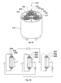
- FIG. 9 a is a perspective view of a battery assembly of a battery bundle and a block diagram of circuitry.
- FIG. 9 b is a partial cross sectional view of the battery bundle of FIG. 9 a.
- FIG. 9 c is a magnified view of portion A of FIG. 9 b.
- FIG. 9 d is a perspective view and partial cutaway view of an energy storage device.
- FIG. 9 e is a block diagram of circuitry of the energy storage device of FIG. 9 d.
- FIG. 10 is a block circuitry diagram for battery bundles.
- FIG. 11 a is a cross sectional view of a battery formed with a mandrel.
- FIG. 11 b is a cross sectional view of the battery of FIG. 11 a without the mandrel.
- FIG. 1 depicts a circular cross-sectional area of metal wire substrate 1 .
- the metal wire 1 works as a current collector with a diameter D, having a range from 5 micron to 500 micron.
- metal wire Prior to deposition, metal wire can be clean as well as textured to a desired surface roughness using mechanical methods such as bead blasting or chemical methods such as a chemical etching method in order to enhance mechanical and chemical bonding between electrode coating and substrate.
- Electrodes with circular cross-section provides an increase in surface area compared to flat rectangular metal sheet or foil electrodes in traditional electrode fabrication.
- An increase in surface area coupled with an decrease in anode film thickness provides a fast charging capability for LIBs, as a reduction in weight and volume for equivalent energy density.
- This novel approach to fabricating solid state batteries on a metal wire enables the design of damage tolerant high density batteries.
- Embodiments of this invention include a method of low cost manufacturing of a silicon-carbon layered composite anode material using thermal chemical vapor deposition (CVD) technology on a long, circular cross-sectional solid or hollow metal wire made of titanium, steel, or tungsten or tin plated cooper.
- CVD thermal chemical vapor deposition
- the most promising means of improving the energy density of today's lithium-ion batteries is to replace the graphite based anode with higher energy density material such as silicon.
- the cycling performance of silicon is often problematic due to the large expansion and shrinkage during insertion and extraction of large amounts of lithium.
- Embodiments of this invention addresses several key issues necessary in obtaining superior Li insertion/extraction performance while maintaining structure integrity. Further, the capacity of a thin silicon film is not enough for practical purposes.
- An embodiment of the present invention addresses this by creating a multi-layer silicon and carbon structure where the carbon layer serves as both an intercalation compound as well as a mechanically compliant layer for management of lithiation induced internal stresses in addition to creating a reaction barrier between the silicon layer and the electrolyte, a porous and/or nano-crystalline microstructure, excellent substrate-film adhesion, and controlled stress state within the film structure.
- the capacity of the silicon-carbon layered composite anode can be tailored by changing thicknesses of individual silicon and carbon layer.
- the invention of fabricating an “anode-on-wire” structure addresses several key factors necessary in obtaining superior Li insertion/extraction performance.
- An appropriate analogy for the anode-on-wire structure is a cylindrical pressure vessel.
- stresses in the anode-on-wire structure arising from electrochemical lithiation in thin film are analogous to stresses in a pressure vessel due to combined pressure loading.
- Silicon expansion and contraction can be likened to internal and external pressure loading, respectively, resulting in a primary tangential or hoop stress component.
- the continuous nature of the hoop stress around the circumference of the cylindrical structure is expected to eliminate the edge effects and stress concentrations common in planar anode structures i.e., lower compressive stress level in the film stack for the circular cross-section geometry as compared to the planar geometry.
- the use of a circular cross-section wire for anode fabrication provides several key benefits as compared to a traditional flat plate anode structure including accommodating volume expansion related stresses.
- a multi-layer thin film porous structure is formed as an electrochemical active material.
- a multistage reactor 20 FIG. 2 is designed to create such an electrochemical active material as described below.
- the wire 1 ( FIG. 1 ) is resistively heated while carbon and/or silicon containing precursors are introduced at various locations to deposit anode material on the circumference of the metal wire 1 .
- Traditional CVD precursors for silicon (such as dichlorosilane) and for carbon (such as methane) are introduced along the length of the reactor 200 ( FIG. 2 ).
- Decomposition of the precursor compound is achieved by a thermal breakdown mechanism when precursor contacts the heated wire surface.
- External plasma sources such as RF or Microwave can also be used to further assist the decomposition rate of active precursor material.
- Amorphous and/or nano-crystalline silicon-carbon layered composite anode material is deposited on moving wire with thicknesses ranging from 2 to 20 ⁇ m depending upon the deposition parameters.
- the speed of the moving wire can be varied to increase or decrease the thickness of deposited anode material.
- Deposition temperature can be varied by resistively heating the metal wire with different current densities while it is moving through the deposition chamber.
- the deposition temperature of the moving wire in different chambers of the reactor 20 can be adjusted by introducing appropriate amount of cooling gas such hydrogen or helium.
- Variation in thickness of the individual coating layers can also be achieved by varying the ratio of chemistry to dilution gas, such as hydrogen or argon, within the process chamber.
- the described manufacturing method is applicable for other suitable anode material for a Li-ion battery.
- FIG. 2 depicts a metal wire 2 continuously moving through the deposition chambers, for example chambers 202 , 204 , 206 , 208 and 210 , in a chemical vapor deposition reactor 200 .
- Tensioners may be used to control tension of the wire and the wire feed collected on reels 214 and 218 .
- amorphous or nano-crystalline carbon-silicon-carbon thick film composite anode is deposited using high vapor pressure precursors for carbon and silicon.
- wire is resistively heated while carbon and/or silicon containing gases are introduced at various locations.
- CVD gasses such as Methane or Acetylene or hexane or any carbon atom containing precursor gas with vapor pressure greater than 0.5 torr can be used. Carbon containing liquid precursor such as dimethyl adamantane can also be used in conjunction with a liquid evaporator and mass flow controller.
- CVD gasses such as mono silane or any variant of silicon containing gas (or high vapor pressure liquid) is used. Gases containing both carbon and silicon constituent such as methyl silane can also be used to form carbon-silicon thick film composite anode.
- Deposition temperature ranges from 200 to 2000 degree Celcius and are achieved by resistively heating the metal wire while it is moving through the deposition chamber. Exhaust gasses are pumped through ports or outlets 222 , 226 , 230 , 234 and 238 .
- anode material is deposited on the circumference of the metal wire 2 as the wire is resistively heated.
- Brush based electrical connection points 240 and 242 provide current for resistive heating.
- H 2 gas is introduced into chamber 202 through inlet 220 for hydrogen etching of wire 2 .
- Exhaust gas is pumped out outlet 222 .
- Silicon precursor is introduced into chamber 204 through inlet 224 for deposition of a silicon adhesion layer on the wire 2 .
- Exhaust gas is pumped out outlet 226 .
- Carbon precursor is introduced into chamber 206 through inlet 228 for deposition of a first carbon coating as a stress compliant layer on the silicon adhesion layer.
- Exhaust gas is pumped out outlet 230 .
- Silicon precursor is introduced into chamber 208 through inlet 232 for deposition of a silicon layer on the carbon layer. Exhaust gas is pumped out outlet 234 . Carbon precursor is introduced into chamber 210 through inlet 236 for deposition of a carbon layer on the silicon layer. Exhaust gases are pumped out of outlet 238 .
- a carbon layer 10 thicker than 10 nm but thinner than 5 microns, is deposited on metal wire current collector 12 followed by deposition of silicon layer 14 of various thicknesses ranging from 1 micron to 100 microns.
- a thin silicon layer 16 thicker than 10 nm but thinner than 5 microns, is deposited followed by a carbon layer 18 with thicknesses ranging from 1 micron to 100 microns.
- alternate layers of carbon 20 and silicon 22 are deposited with thickness ranging from 10 nm to 100 microns. Based on these embodiments, various other configurations of silicon and carbon layers are possible such as the deposition of a single layer of silicon or a single layer of carbon on a metal wire as described above.
- FIG. 4 a illustrates a metal wire 12 moving through the deposition chamber 32 guided into the chamber by guide rollers 33 .
- a cover 34 is placed over the metal wire at desired locations along the length of the wire to prevent deposition at selected areas along the length of a metal wire 12 moving through the deposition chamber 32 .
- the distance between cover placement 36 ( FIG. 4 b ) along the length of metal wire substrate can vary depending upon the size of anode wire ( FIG. 4 c ) that is needed for a particular application.
- This cover can be made of ceramic or metal sheet.
- the moving wire is resistively heated while silicon and/or carbon containing precursor gasses are introduced at locations along with diluting gases such as hydrogen or inert gas.
- a hydrogen enriched silicon layer includes 10-80% hydrogen.
- an argon enriched carbon layer includes 10-80% argon.
- Process conditions such as pressure, temperature, flow rates and precursor gases to diluting gases ratio are varied so that hydrogen and/or inert gas is trapped within the growing anode layers.
- the anode coated wire is passed through a vacuum chamber while heated resistively above 1000 degree Celsius. This causes trapped hydrogen and/or inert gas within the anode layers to escape creating diffusion paths and a porous structure.
- This method can be applied to create porous cathode structure resulting in more rapid charging/discharging of battery.
- This structure is shown in FIGS. 5 a and 5 b , with metal wire 12 anode coating 42 and pores 44 .
- the following steps are an example method used to create such structure.
- Embodiments of the present invention relate to method of manufacturing a cathode active material on a long circular cross-sectional metal wire substrate.
- This metal wire substrate performs as current collector in an electrochemical cell.
- the cathode material (such as LiCoO2) is deposited on a metal wire employing a method similar to anode formation as described above but with using cathode forming precursors, physical vapor deposition, thermal spray, spray pyrolysis, sol gel and applicable powder metallurgy method using cathode material and/or cathode material precursor with or without binding material. Liquid phase deposition could also be used.
- cathode material is deposited on a metal wire substrate resistively heated at temperatures ranging from 100 degree Celsius to 2000 degree Celsius. As the coefficient of thermal expansion of metal wire substrate is higher than the cathode material, strain is introduced within the cathode material and higher level of strain induced crystallization is achieved.
- an innovative low cost annealing technique to heat treat the deposited cathode material is provided. After deposition of the cathode material on the metal wire substrate, in a sequential step, an electric current is passed through the metal substrate for resistively heating the substrate to desired temperature to induce desired diffusion, crystallization and bonding within deposited cathode material.
- FIG. 6 is a schematic of a device for a low cost elevated temperature annealing method for deposited cathode.
- a continuous as-deposited cathode metal wire 50 is passed through an annealing chamber 52 from a wire reel 54 to a receiving reel 56 .
- An electric current is passed through the metal wire by power supply 60 using uncoated area ( FIG. 4 ) at connection points 58 heating the metal wire resistively.
- Temperature can be monitored using sensor 62 and controlled by feedback to the power supply 60 .
- Set-point electrical current can also be applied thru the deposited material.
- the temperature of the coated metal wire can be controlled by varying the input current for resistance heating and ranges from 200 C to 2000 C.
- Various environments such as oxygen or nitrogen or fluorine can be introduced during the annealing process.
- FIGS. 7 a and 7 b are cross-sectional longitudinal and side views of annealed cathode material 70 on a wire substrate 12 .
- the degree of crystallization is controlled by varying the temperature and time with an increase in temperature and/or time resulting in an increase in crystal size.
- wire is resistively heated while silicon and/or carbon containing gasses are introduced in the chemical vapor deposition reactor 200 ( FIG. 2 ) along with hydrogen or inert gas such as argon for anode formation as described above.
- hydrogen or inert gas such as argon for anode formation as described above.
- Process conditions are varied so that hydrogen and/or inert gas get trapped within the growing porosity forming coating.
- cathode material as per the teachings described above.
- FIGS. 7 c and 7 d depict annealed cathode 74 with porous structures 76 and a thin base carbon layer 80 deposited on wire substrate 12 .
- the carbon layer is thinner than 5 micrometers and is deposited as described above for anode formation in FIG. 5 before deposition of cathode material. Further understanding of the nature and advantages of the present invention may be realized by reference to the latter portions of the specification and attached drawings.
- a solid state battery can be manufactured where an electrochemical cell structure will be created on an integral high surface area metal wire substrate with circular cross section.
- An advantage of embodiments of this invention are that, for example, they result in a battery structure that combines excellent performance characteristics of a solid state battery (excellent cycle and calendar life, high Depth of Discharge, rapid charging rate) with the high energy capacity of a traditional battery fabricated using powder based active materials.
- This low cost continuous manufacturing technology may be used to create a three dimensional array of high capacity, porous film based “battery-on-wire” structures.
- Individual “batteries-on-wire” of different diameters are bundled to improve packing density and connected in series or parallel, as required by the application, to form a high capacity battery.
- the bundled “battery-on-wire” can be as long as required by application changing the length of individual wire.
- the “battery-on-wire” technology has the potential to create a LIB with extremely high charge-discharge rate with sufficient energy density and cycle life.
- Embodiments of this invention may accomplish high charge-discharge rate by reducing the path length over which the electrons and Li ions move by the use of a multilayer porous film structure coupled with large surface area and increased anode capacity based on silicon.
- Embodiments of this invention may achieve high specific energy density of the “battery-on-wire” structure by combining wire geometry with a high capacity three dimensional porous silicon containing anode and a less than 2 micron thick electrolyte layer, resulting in a significant improvement in both volumetric and gravimetric capacities.
- a method of manufacture of a solid state Li-ion battery comprises the following steps: (1) depositing an active anode material 82 on a metal wire 12 as described in above teaching, (2) depositing a lithium phosphorous oxy nitride (LIPON) or other suitable electrolyte 84 using standard deposition techniques or as described in above teaching for anode fabrication using appropriate electrolyte precursors (3) depositing an active cathode material 86 as described in above teaching, 4) elevated thermal annealing of deposited cathode material to induce desired level of crystallization in selected environments as described above, and 5) metal current collector electrode 88 deposition using precursors of conductive metals such as Al, Cu, or W by an established method such as plasma spray or physical vapor deposition or sputtering.
- LIPON lithium phosphorous oxy nitride
- solid state LIBs 90 are manufactured by: 1) depositing an active cathode material 92 on a metal wire 12 as described in above teaching, (2) a elevated thermal annealing of deposited cathode material 12 to induce desired level of crystallization in selected environments as described above, (3) depositing a lithium salt such as lithium phosphorous oxy nitride (LIPON) or other suitable electrolyte 94 using standard deposition technique or as described in the above teaching for anode fabrication using appropriate electrolyte precursors, (4) depositing an active anode material 96 as described in above teachings and (5) metal current collector 98 deposition using precursor of conductive metals such as Al, Cu, or W by an established deposition method such as plasma spray or physical vapor or sputtering.
- a power source is indicated by the letter P.
- an LIB 101 is shown comprised of: an anode on metal wire 100 fabricated with the teachings describe above with liquid electrolyte 102 such as LiPF6 and traditional foil based cathode 104 such as LiCoO2 on copper foil with a separator 106 .
- Anode on metal wire can be of various geometrical forms such as woven, cross-weave, hollow spiral, multiple stacks etc. The anode on wire configuration provides tremendous geometric and functional capability to the manufacturing technique.
- cathode on metal wire 112 fabricated with the teachings describe above is used with liquid electrolyte 114 such as LiPF6 and traditional foil based anode 116 such as graphite on aluminum foil with a separator 118 .
- liquid electrolyte 114 such as LiPF6
- traditional foil based anode 116 such as graphite on aluminum foil with a separator 118 .
- Cathode on metal wire 112 can be of various geometrical forms such as woven, cross-weave, hollow spiral, multiple stacks etc. The cathode on wire configuration provides tremendous geometric and functional capability to the manufacturing technique.
- both anode and cathode on separate metal wires fabricated with the teachings describe above can be used with a liquid electrolyte such as LiPF6 or polymeric electrolyte along with a separator to fabricate a lithium ion battery.
- a liquid electrolyte such as LiPF6 or polymeric electrolyte
- separator to fabricate a lithium ion battery.
- Both anode and cathode on metal wire can be of various geometrical forms such as woven, cross-weave, hollow spiral, multiple stacks etc.
- the active component formation on wire configuration provides tremendous geometric and functional capability to the manufacturing technique.
- magnetic field induced due to flow of current through the metal wire substrate can be harvested by arranging metal wire battery parallel, series or cross weave pattern to enhance internal potential of electrochemical cell.
- Embodiments of this invention facilitates implementation of control circuitry for charging and safety at both the single as well as the multiple bundle level allowing fabrication of a damage tolerant and inherently safe battery structure.
- Existing foil-based cells require external protection circuitry to prevent thermal runaway and/or cell rupture in the event of anode-cathode shorting. These external protection circuits reduce the volumetric efficiency of a given cell and often require parasitic current draw from the cell which is being protected.
- the proposed “battery-on-wire” cell structure can act as an integrated protection circuit, based on the principle of a thermal switch.
- the current carrying capacity of the “battery-on-wire” will be designed by selecting appropriate wire diameter such that the wire will melt at predesigned location and open the circuit in the event of anode-cathode shorting, effectively making each individual “battery-on-wire” in the bundle a thermal switch.
- the “battery-on-wire” structure is expected to provide superior safety, improved volumetric efficiency and require no parasitic current draw for maintenance of an external protection circuit.
- each battery 901 of the bundle 900 includes a conductive metal wire substrate 904 , an anode material layer 906 deposited on the metal wire substrate spaced apart from a cathode material layer 910 , an electrolyte 908 disposed in the space between the anode material layer and the cathode layer and a top current collector 912 .
- the diameter of the metal wire 904 within the bundle 900 ranges from 2-500 micron and is selected appropriately to improve packing density within the bundle.
- FIG. 9 a depicts a single bundle 900 of an array of batteries-on-wires connected in parallel.
- the bundle includes a polymer casing 903 .
- diameter and length of individual wire as well as number of the wire in a bundle can be changed.
- the high density battery 902 may be packaged in a polymer sheath 914 .
- Anode terminal 904 , anode connection wires 906 and cathode connection is shown to form the monolithic battery 902 .
- Single wire batteries 901 can be connected in parallel as required by the application. These bundled wire batteries can be as long as required limited by the length of an individual wire battery.
- top current collectors 912 are made of conductive metal including for example steel, tungsten, or coated metals, or ceramic wire.
- Top current collectors 912 are made of conductive metal including for example steel, tungsten, or coated metals, or ceramic wire.
- Hundreds of single battery wires can be connected in parallel to form one battery bundle 900 .
- the number and length of wire can be increased as required by application while appropriate single battery wire diameter can be selected to improve packing density of single bundle.
- an individual battery 901 may have a diameter greater than 50 micrometers and may be up to 10 miles long.
- several bundles 900 can be connected in series to generate the required application voltage.
- Several bundles depicted in FIG. 9 e are connected in series to make a higher capacity battery. Depending upon the application requirements the number of bundles in a battery can be increased.
- This concept facilitates implementation of control circuitry for charging and safety at both, the single as well as the multiple bundle level. Isolation of the metal cores from the bundled ends is required in the end region of each group to prevent local shorting of the anode and cathode for a robust battery. This is achieved by placing a cover or spacer over the metal wire before wire enters the deposition chamber as described in FIGS. 4 a and 4 b . Exemplary configurations described herein are for illustration purposes only and they do not intend to limit the full scope of the possible configurations and combinations that can be achieved following the principles of the present disclosure.
- damage tolerant battery design embodiments are described.
- bundles 1000 a - e of single energy wire are connected in series by series connection 142 to form a high energy density battery 1002 connected, for example, to a power source 132 .
- fabrication of a high energy density battery, as described, including multiple low energy wire battery allows damage 134 to the battery 1002 where only the damaged wire batteries 1000 a and 1000 c become non-functional while other bundle wire battery 1000 b , 1000 d , and 1000 e perform although with lower energy output.
- the application of this invention prevents release of large amount of energy due to shorting between anode and cathode within energy wire bundle. Anode-cathode shorting due to damage releases low energy only from the damage single wire battery bundle as compared to foil based design where large amounts of energy can be released.
- Embodiments of the present invention also offer a high degree of flexibility as compared with conventional approaches and offer significant advantages as presented in electrochemical cell in FIGS. 11 a and 11 b .
- anode and cathode wire can be used to create a spiral structure.
- an anode wire 151 with integrated separator 152 is wrapped around a mandrel tube 150 with holes. This is followed by wrapping a cathode wire 153 and casing material 154 .
- Anode wire 151 and cathode wire 153 are used as current collector. Both the anode and cathode may be made from, for example, conductive metal, coated metal, metal coated oxide, or carbon wire.
- Mandrel tube 150 is filled with standard electrolyte such as LiPF6 to make a spiral wire battery. These spiral wire batteries can be as long as required limited by the length of mandrel tube 150 . Several other modification of such approach is envisioned. In another embodiment as described in FIG. 11 b , hollow mandrel tube 150 is removed after filling with liquid electrolyte 157 with casing material 158 providing containment. Such spiral structure can also be created using solid state battery wire ( FIG. 8 ) with and without mandrel tube 150 using the method described above. Exemplary configurations described herein are for illustration purposes only and they do not intend to limit the full scope of the possible configurations and combinations that can be achieved following the principles of the present disclosure.
Landscapes
- Chemical & Material Sciences (AREA)
- Chemical Kinetics & Catalysis (AREA)
- Electrochemistry (AREA)
- General Chemical & Material Sciences (AREA)
- Engineering & Computer Science (AREA)
- Manufacturing & Machinery (AREA)
- Materials Engineering (AREA)
- Composite Materials (AREA)
- Inorganic Chemistry (AREA)
- Cell Electrode Carriers And Collectors (AREA)
- Battery Electrode And Active Subsutance (AREA)
- Secondary Cells (AREA)
Priority Applications (7)
| Application Number | Priority Date | Filing Date | Title |
|---|---|---|---|
| US13/708,137 US8993172B2 (en) | 2011-12-10 | 2012-12-07 | Li-ion battery and battery active components on metal wire |
| CN201280060612.9A CN104137318A (zh) | 2011-12-10 | 2012-12-10 | 金属线上的锂离子电池和电池活性元件 |
| KR1020147017851A KR20140103998A (ko) | 2011-12-10 | 2012-12-10 | 금속 와이어 상의 리튬 이온 배터리 및 배터리 활성 구성요소 |
| JP2014546176A JP2015505127A (ja) | 2011-12-10 | 2012-12-10 | リチウムイオン電池および金属ワイヤー上の電池活性構成要素 |
| PCT/US2012/068778 WO2013086508A1 (en) | 2011-12-10 | 2012-12-10 | Li-ion battery and battery active components on metal wire |
| US14/557,233 US9559380B2 (en) | 2011-12-10 | 2014-12-01 | Li-ion battery and battery active components on metal wire |
| US15/400,585 US20170117573A1 (en) | 2011-12-10 | 2017-01-06 | Li-ion battery and battery active components on metal wire |
Applications Claiming Priority (4)
| Application Number | Priority Date | Filing Date | Title |
|---|---|---|---|
| US201161569228P | 2011-12-10 | 2011-12-10 | |
| US201261587632P | 2012-01-17 | 2012-01-17 | |
| US201261587659P | 2012-01-18 | 2012-01-18 | |
| US13/708,137 US8993172B2 (en) | 2011-12-10 | 2012-12-07 | Li-ion battery and battery active components on metal wire |
Related Child Applications (1)
| Application Number | Title | Priority Date | Filing Date |
|---|---|---|---|
| US14/557,233 Division US9559380B2 (en) | 2011-12-10 | 2014-12-01 | Li-ion battery and battery active components on metal wire |
Publications (2)
| Publication Number | Publication Date |
|---|---|
| US20130344363A1 US20130344363A1 (en) | 2013-12-26 |
| US8993172B2 true US8993172B2 (en) | 2015-03-31 |
Family
ID=48574984
Family Applications (3)
| Application Number | Title | Priority Date | Filing Date |
|---|---|---|---|
| US13/708,137 Expired - Fee Related US8993172B2 (en) | 2011-12-10 | 2012-12-07 | Li-ion battery and battery active components on metal wire |
| US14/557,233 Expired - Fee Related US9559380B2 (en) | 2011-12-10 | 2014-12-01 | Li-ion battery and battery active components on metal wire |
| US15/400,585 Abandoned US20170117573A1 (en) | 2011-12-10 | 2017-01-06 | Li-ion battery and battery active components on metal wire |
Family Applications After (2)
| Application Number | Title | Priority Date | Filing Date |
|---|---|---|---|
| US14/557,233 Expired - Fee Related US9559380B2 (en) | 2011-12-10 | 2014-12-01 | Li-ion battery and battery active components on metal wire |
| US15/400,585 Abandoned US20170117573A1 (en) | 2011-12-10 | 2017-01-06 | Li-ion battery and battery active components on metal wire |
Country Status (5)
| Country | Link |
|---|---|
| US (3) | US8993172B2 (cg-RX-API-DMAC7.html) |
| JP (1) | JP2015505127A (cg-RX-API-DMAC7.html) |
| KR (1) | KR20140103998A (cg-RX-API-DMAC7.html) |
| CN (1) | CN104137318A (cg-RX-API-DMAC7.html) |
| WO (1) | WO2013086508A1 (cg-RX-API-DMAC7.html) |
Cited By (11)
| Publication number | Priority date | Publication date | Assignee | Title |
|---|---|---|---|---|
| US9570775B2 (en) | 2013-03-15 | 2017-02-14 | Apple Inc. | Thin film transfer battery systems |
| US9711770B2 (en) | 2012-11-27 | 2017-07-18 | Apple Inc. | Laminar battery system |
| US9887403B2 (en) | 2013-03-15 | 2018-02-06 | Apple Inc. | Thin film encapsulation battery systems |
| US9899661B2 (en) | 2013-03-13 | 2018-02-20 | Apple Inc. | Method to improve LiCoO2 morphology in thin film batteries |
| US10033029B2 (en) | 2012-11-27 | 2018-07-24 | Apple Inc. | Battery with increased energy density and method of manufacturing the same |
| US10141600B2 (en) | 2013-03-15 | 2018-11-27 | Apple Inc. | Thin film pattern layer battery systems |
| US10211433B2 (en) | 2012-11-27 | 2019-02-19 | Apple Inc. | Battery packaging |
| US10221485B2 (en) | 2014-01-09 | 2019-03-05 | Adavolt, Inc. | High energy density solid state lithium ion battery with fail-safe |
| US10930915B2 (en) | 2014-09-02 | 2021-02-23 | Apple Inc. | Coupling tolerance accommodating contacts or leads for batteries |
| US11824220B2 (en) | 2020-09-03 | 2023-11-21 | Apple Inc. | Electronic device having a vented battery barrier |
| US11842849B2 (en) | 2020-04-27 | 2023-12-12 | Capacitech Energy, Inc. | Energy storage device and method of making |
Families Citing this family (44)
| Publication number | Priority date | Publication date | Assignee | Title |
|---|---|---|---|---|
| US9409777B2 (en) | 2012-02-09 | 2016-08-09 | Basf Se | Preparation of polymeric resins and carbon materials |
| KR101465168B1 (ko) * | 2013-01-03 | 2014-11-25 | 주식회사 엘지화학 | 케이블형 이차전지 |
| WO2014143213A1 (en) | 2013-03-14 | 2014-09-18 | Energ2 Technologies, Inc. | Composite carbon materials comprising lithium alloying electrochemical modifiers |
| US9601751B2 (en) * | 2013-03-15 | 2017-03-21 | Apple Inc. | Annealing method for thin film electrodes |
| WO2014178590A1 (ko) | 2013-04-29 | 2014-11-06 | 주식회사 엘지화학 | 케이블형 이차전지용 패키징 및 그를 포함하는 케이블형 이차전지 |
| WO2014182063A1 (ko) | 2013-05-07 | 2014-11-13 | 주식회사 엘지화학 | 이차전지용 전극, 그의 제조방법, 그를 포함하는 이차전지 및 케이블형 이차전지 |
| JP6038298B2 (ja) | 2013-05-07 | 2016-12-07 | エルジー・ケム・リミテッド | ケーブル型二次電池及びその製造方法 |
| EP2830126B1 (en) | 2013-05-07 | 2019-07-03 | LG Chem, Ltd. | Electrode for secondary battery, preparation thereof, and secondary battery and cable-type secondary battery comprising the same |
| KR101465164B1 (ko) * | 2013-05-07 | 2014-11-25 | 주식회사 엘지화학 | 케이블형 이차전지 |
| WO2014182064A1 (ko) | 2013-05-07 | 2014-11-13 | 주식회사 엘지화학 | 이차전지용 전극, 그의 제조방법, 그를 포함하는 이차전지 및 케이블형 이차전지 |
| WO2014182062A1 (ko) | 2013-05-07 | 2014-11-13 | 주식회사 엘지화학 | 이차전지용 전극, 그의 제조방법, 그를 포함하는 이차전지 및 케이블형 이차전지 |
| DE202014010605U1 (de) * | 2013-05-07 | 2016-02-18 | Lg Chem, Ltd. | Kabelartige Sekundärbatterie |
| US9620298B2 (en) * | 2013-10-25 | 2017-04-11 | University Of Central Florida Research Foundation, Inc. | Nanofeatured electrodes and energy storage coaxial cables therefrom |
| US10195583B2 (en) | 2013-11-05 | 2019-02-05 | Group 14 Technologies, Inc. | Carbon-based compositions with highly efficient volumetric gas sorption |
| CA2940598C (en) * | 2014-02-26 | 2023-08-01 | Universidade Do Porto | A solid electrolyte glass for lithium or sodium ions conduction |
| CN103904357B (zh) * | 2014-03-09 | 2016-03-02 | 宁国市龙晟柔性储能材料科技有限公司 | 一种可拉伸的线状锂离子电池及其制备方法 |
| KR102347131B1 (ko) | 2014-03-14 | 2022-01-04 | 그룹14 테크놀로지스, 인코포레이티드 | 용매의 부재하의 졸-겔 중합을 위한 신규한 방법 및 그러한 방법으로부터의 가변형 탄소 구조의 생성 |
| FR3025055B1 (fr) * | 2014-08-19 | 2016-08-26 | Jomi Leman | Dispositif electrochimique pour le stockage de l'energie electrique et la production d'hydrogene, et procede de production d'hydrogene |
| CN104617336B (zh) * | 2015-02-12 | 2017-04-19 | 中国工程物理研究院化工材料研究所 | 一种线性柔性的锂离子电池及其制备方法 |
| US10205187B2 (en) * | 2015-04-03 | 2019-02-12 | Intel Corporation | Constrained anode fiber for rechargeable battery |
| WO2017031006A1 (en) | 2015-08-14 | 2017-02-23 | Energ2 Technologies, Inc. | Composites of porous nano-featured silicon materials and carbon materials |
| JP7115976B2 (ja) | 2015-08-28 | 2022-08-09 | グループ14・テクノロジーズ・インコーポレイテッド | リチウムの非常に耐久性のある挿入を有する新規な材料およびその製造方法 |
| KR102040256B1 (ko) * | 2015-08-31 | 2019-11-04 | 주식회사 엘지화학 | 케이블형 이차 전지 |
| KR102070369B1 (ko) * | 2015-09-03 | 2020-01-28 | 주식회사 엘지화학 | 케이블형 이차전지 및 이의 제조방법 |
| WO2017119799A1 (ko) * | 2016-01-07 | 2017-07-13 | 주식회사 엘지화학 | 케이블형 이차전지의 제조 장치 및 방법과 그에 따라 제조된 케이블형 이차전지 |
| JP2019526151A (ja) | 2016-07-11 | 2019-09-12 | ボード・オブ・リージエンツ,ザ・ユニバーシテイ・オブ・テキサス・システム | 金属めっきベースの電気エネルギー貯蔵セル |
| KR102798089B1 (ko) | 2017-03-09 | 2025-04-21 | 그룹14 테크놀로지스, 인코포레이티드 | 다공성 스캐폴드 재료 상의 실리콘 함유 전구체의 분해 |
| GB201704295D0 (en) * | 2017-03-17 | 2017-05-03 | Dyson Technology Ltd | Energy storage device |
| GB201704294D0 (en) | 2017-03-17 | 2017-05-03 | Dyson Technology Ltd | Energy storage device |
| GB201704293D0 (en) | 2017-03-17 | 2017-05-03 | Dyson Technology Ltd | Energy storage device |
| GB201704292D0 (en) | 2017-03-17 | 2017-05-03 | Dyson Technology Ltd | Energy storage device |
| US10490360B2 (en) | 2017-10-12 | 2019-11-26 | Board Of Regents, The University Of Texas System | Heat energy-powered electrochemical cells |
| CN111418028A (zh) * | 2017-10-26 | 2020-07-14 | 古河电气工业株式会社 | 碳纳米管包覆电线 |
| CN111373493A (zh) * | 2017-10-26 | 2020-07-03 | 古河电气工业株式会社 | 碳纳米管包覆电线 |
| KR102261183B1 (ko) * | 2017-11-22 | 2021-06-07 | 주식회사 엘지에너지솔루션 | 케이블형 배터리 |
| US11011742B2 (en) * | 2019-06-10 | 2021-05-18 | GM Global Technology Operations LLC | Silicon embedded copper anodes and battery cells incorporating the same |
| KR102883984B1 (ko) | 2020-03-09 | 2025-11-07 | 삼성전자주식회사 | 전고체 이차 전지 및 그 제조방법 |
| US11174167B1 (en) | 2020-08-18 | 2021-11-16 | Group14 Technologies, Inc. | Silicon carbon composites comprising ultra low Z |
| US11639292B2 (en) | 2020-08-18 | 2023-05-02 | Group14 Technologies, Inc. | Particulate composite materials |
| US11335903B2 (en) | 2020-08-18 | 2022-05-17 | Group14 Technologies, Inc. | Highly efficient manufacturing of silicon-carbon composites materials comprising ultra low z |
| EP4222109A1 (en) | 2020-09-30 | 2023-08-09 | Group14 Technologies, Inc. | Methods of passivation to control oxygen content and reactivity of silicon-carbon composite materials |
| JP7726052B2 (ja) * | 2021-12-13 | 2025-08-20 | セイコーエプソン株式会社 | 印刷装置 |
| CN115832161B (zh) * | 2022-03-29 | 2024-12-24 | 宁德时代新能源科技股份有限公司 | 电极组件、电池单体、电池和用电设备 |
| CN116093287B (zh) * | 2022-12-30 | 2025-03-11 | 四川物科金硅新材料科技有限责任公司 | 一种负极材料及其制备方法、负极极片和锂离子电池 |
Citations (33)
| Publication number | Priority date | Publication date | Assignee | Title |
|---|---|---|---|---|
| US2734478A (en) | 1956-02-14 | Copper | ||
| US3313269A (en) | 1964-08-11 | 1967-04-11 | Ralph L Hough | Vapor plating apparatus |
| US3542604A (en) | 1965-02-24 | 1970-11-24 | Mc Donnell Douglas Corp | Thermal battery |
| US3562002A (en) | 1968-04-24 | 1971-02-09 | Air Reduction | Method and apparatus for vapor deposition |
| US3622369A (en) | 1967-02-24 | 1971-11-23 | United Aircraft Corp | Process for forming stoichiometric silicon carbide coatings and filaments |
| US4410608A (en) | 1981-12-21 | 1983-10-18 | Gte Products Corporation | Electrochemical cell |
| US4522897A (en) | 1983-10-14 | 1985-06-11 | Cape Cod Research, Inc. | Rope batteries |
| US4675259A (en) | 1986-02-25 | 1987-06-23 | Halliburton Company | Electrical energy package and method of assembly |
| WO1995005499A1 (en) | 1993-08-13 | 1995-02-23 | Imperial Chemical Industries | Electrode and preparation thereof |
| US5510212A (en) | 1993-01-13 | 1996-04-23 | Delnick; Frank M. | Structural micro-porous carbon anode for rechargeable lithium ion batteries |
| US5571561A (en) | 1992-10-27 | 1996-11-05 | The Secretary Of State For Defence In Her Britannic Majesty's Government Of The United Kingdom Of Great Britain And Northern Ireland | Coated filaments |
| US5909104A (en) | 1998-02-26 | 1999-06-01 | Motorola, Inc. | Electrostatic enhanced lithium battery circuit |
| KR20040025127A (ko) | 2002-09-18 | 2004-03-24 | 엘지전자 주식회사 | 전자레인지의 랙선반 장착구조 |
| US6746802B2 (en) | 2001-03-08 | 2004-06-08 | Sanyo Electric Co., Ltd. | Electrode for lithium secondary battery and lithium secondary battery |
| US20050084759A1 (en) | 2001-12-28 | 2005-04-21 | Mariko Miyachi | Lithium-ion secondary battery |
| KR20050099903A (ko) | 2004-04-12 | 2005-10-17 | 경상대학교산학협력단 | 실형태의 가변형 전지 |
| US7202000B2 (en) | 2001-07-31 | 2007-04-10 | Nec Corporation | Anode for secondary battery, secondary battery using same and method for fabricating anode |
| US7351449B2 (en) | 2000-09-22 | 2008-04-01 | N Gimat Co. | Chemical vapor deposition methods for making powders and coatings, and coatings made using these methods |
| US20080137890A1 (en) * | 2005-01-20 | 2008-06-12 | Oticon A/S | Hearing Aid with Rechargeable Battery and Rechargeable Battery |
| US20080268343A1 (en) | 2007-04-27 | 2008-10-30 | Toshitada Sato | Electrochemical element and electrode thereof, method and apparatus for manufacturing the electrode, method and apparatus for lithiation treatment |
| US20100047574A1 (en) | 2008-08-22 | 2010-02-25 | Ray Paul Durman | Coated filaments and their manufacture |
| US7717968B2 (en) | 2006-03-08 | 2010-05-18 | Yevgen Kalynushkin | Electrode for energy storage device and method of forming the same |
| US20100203372A1 (en) * | 2007-07-20 | 2010-08-12 | Industry-Academic Cooperation Foundation Gyeonsan National University | Wire type batteries for wireless charge |
| US20100261071A1 (en) | 2009-04-13 | 2010-10-14 | Applied Materials, Inc. | Metallized fibers for electrochemical energy storage |
| US20120009331A1 (en) | 2010-02-02 | 2012-01-12 | Lg Chem, Ltd. | Method For Manufacturing Cable-Type Secondary Battery |
| US20120015239A1 (en) | 2010-02-01 | 2012-01-19 | Lg Chem, Ltd. | Cable-Type Secondary Battery |
| US20120015233A1 (en) | 2010-02-01 | 2012-01-19 | Lg Chem, Ltd. | Cable-Type Secondary Battery |
| US20120058376A1 (en) | 2010-02-01 | 2012-03-08 | Lg Chem, Ltd. | Cable-type secondary battery |
| US20120100440A1 (en) | 2010-10-20 | 2012-04-26 | Ut-Battelle, Llc. | Multi-layered, chemically bonded lithium-ion and lithium/air batteries |
| US20120100408A1 (en) | 2010-10-20 | 2012-04-26 | Lg Chem, Ltd. | Cable-type secondary battery and method for manufacturing the same |
| US20120100415A1 (en) | 2010-10-21 | 2012-04-26 | Lg Chem, Ltd. | Cable-type secondary battery and method for manufacturing the same |
| US20120148902A1 (en) * | 2010-05-20 | 2012-06-14 | Yo-Han Kwon | Cable-type secondary battery having metal-coated polymer current collector |
| US20120156554A1 (en) | 2010-11-04 | 2012-06-21 | Lg Chem, Ltd. | Cable-Type Secondary Battery And Manufacturing Method Thereof |
Family Cites Families (1)
| Publication number | Priority date | Publication date | Assignee | Title |
|---|---|---|---|---|
| CN102214817A (zh) * | 2010-04-09 | 2011-10-12 | 清华大学 | 一种碳/硅/碳纳米复合结构负极材料及其制备方法 |
-
2012
- 2012-12-07 US US13/708,137 patent/US8993172B2/en not_active Expired - Fee Related
- 2012-12-10 WO PCT/US2012/068778 patent/WO2013086508A1/en not_active Ceased
- 2012-12-10 CN CN201280060612.9A patent/CN104137318A/zh active Pending
- 2012-12-10 KR KR1020147017851A patent/KR20140103998A/ko not_active Withdrawn
- 2012-12-10 JP JP2014546176A patent/JP2015505127A/ja active Pending
-
2014
- 2014-12-01 US US14/557,233 patent/US9559380B2/en not_active Expired - Fee Related
-
2017
- 2017-01-06 US US15/400,585 patent/US20170117573A1/en not_active Abandoned
Patent Citations (34)
| Publication number | Priority date | Publication date | Assignee | Title |
|---|---|---|---|---|
| US2734478A (en) | 1956-02-14 | Copper | ||
| US3313269A (en) | 1964-08-11 | 1967-04-11 | Ralph L Hough | Vapor plating apparatus |
| US3542604A (en) | 1965-02-24 | 1970-11-24 | Mc Donnell Douglas Corp | Thermal battery |
| US3622369A (en) | 1967-02-24 | 1971-11-23 | United Aircraft Corp | Process for forming stoichiometric silicon carbide coatings and filaments |
| US3562002A (en) | 1968-04-24 | 1971-02-09 | Air Reduction | Method and apparatus for vapor deposition |
| US4410608A (en) | 1981-12-21 | 1983-10-18 | Gte Products Corporation | Electrochemical cell |
| US4522897A (en) | 1983-10-14 | 1985-06-11 | Cape Cod Research, Inc. | Rope batteries |
| US4675259A (en) | 1986-02-25 | 1987-06-23 | Halliburton Company | Electrical energy package and method of assembly |
| US5571561A (en) | 1992-10-27 | 1996-11-05 | The Secretary Of State For Defence In Her Britannic Majesty's Government Of The United Kingdom Of Great Britain And Northern Ireland | Coated filaments |
| US5510212A (en) | 1993-01-13 | 1996-04-23 | Delnick; Frank M. | Structural micro-porous carbon anode for rechargeable lithium ion batteries |
| WO1995005499A1 (en) | 1993-08-13 | 1995-02-23 | Imperial Chemical Industries | Electrode and preparation thereof |
| US5909104A (en) | 1998-02-26 | 1999-06-01 | Motorola, Inc. | Electrostatic enhanced lithium battery circuit |
| US7351449B2 (en) | 2000-09-22 | 2008-04-01 | N Gimat Co. | Chemical vapor deposition methods for making powders and coatings, and coatings made using these methods |
| US6746802B2 (en) | 2001-03-08 | 2004-06-08 | Sanyo Electric Co., Ltd. | Electrode for lithium secondary battery and lithium secondary battery |
| US7202000B2 (en) | 2001-07-31 | 2007-04-10 | Nec Corporation | Anode for secondary battery, secondary battery using same and method for fabricating anode |
| US20050084759A1 (en) | 2001-12-28 | 2005-04-21 | Mariko Miyachi | Lithium-ion secondary battery |
| KR20040025127A (ko) | 2002-09-18 | 2004-03-24 | 엘지전자 주식회사 | 전자레인지의 랙선반 장착구조 |
| US20070243456A1 (en) | 2004-04-12 | 2007-10-18 | Gyeongsang National University | Thread-Type Flexible Battery |
| KR20050099903A (ko) | 2004-04-12 | 2005-10-17 | 경상대학교산학협력단 | 실형태의 가변형 전지 |
| US20080137890A1 (en) * | 2005-01-20 | 2008-06-12 | Oticon A/S | Hearing Aid with Rechargeable Battery and Rechargeable Battery |
| US7717968B2 (en) | 2006-03-08 | 2010-05-18 | Yevgen Kalynushkin | Electrode for energy storage device and method of forming the same |
| US20080268343A1 (en) | 2007-04-27 | 2008-10-30 | Toshitada Sato | Electrochemical element and electrode thereof, method and apparatus for manufacturing the electrode, method and apparatus for lithiation treatment |
| US20100203372A1 (en) * | 2007-07-20 | 2010-08-12 | Industry-Academic Cooperation Foundation Gyeonsan National University | Wire type batteries for wireless charge |
| US20100047574A1 (en) | 2008-08-22 | 2010-02-25 | Ray Paul Durman | Coated filaments and their manufacture |
| US20100261071A1 (en) | 2009-04-13 | 2010-10-14 | Applied Materials, Inc. | Metallized fibers for electrochemical energy storage |
| US20120015239A1 (en) | 2010-02-01 | 2012-01-19 | Lg Chem, Ltd. | Cable-Type Secondary Battery |
| US20120015233A1 (en) | 2010-02-01 | 2012-01-19 | Lg Chem, Ltd. | Cable-Type Secondary Battery |
| US20120058376A1 (en) | 2010-02-01 | 2012-03-08 | Lg Chem, Ltd. | Cable-type secondary battery |
| US20120009331A1 (en) | 2010-02-02 | 2012-01-12 | Lg Chem, Ltd. | Method For Manufacturing Cable-Type Secondary Battery |
| US20120148902A1 (en) * | 2010-05-20 | 2012-06-14 | Yo-Han Kwon | Cable-type secondary battery having metal-coated polymer current collector |
| US20120100440A1 (en) | 2010-10-20 | 2012-04-26 | Ut-Battelle, Llc. | Multi-layered, chemically bonded lithium-ion and lithium/air batteries |
| US20120100408A1 (en) | 2010-10-20 | 2012-04-26 | Lg Chem, Ltd. | Cable-type secondary battery and method for manufacturing the same |
| US20120100415A1 (en) | 2010-10-21 | 2012-04-26 | Lg Chem, Ltd. | Cable-type secondary battery and method for manufacturing the same |
| US20120156554A1 (en) | 2010-11-04 | 2012-06-21 | Lg Chem, Ltd. | Cable-Type Secondary Battery And Manufacturing Method Thereof |
Non-Patent Citations (2)
| Title |
|---|
| English translation: U.S. Appl. No. 11/578,045, corresponding to Korean appln. 10-2004-0025127, 18 pages. |
| Paper: E.F. Vaage, "Transmission Properties of Laminated Clogston Type Conductors", Bell Systems Technical Journal, May 1953, 20 pages. |
Cited By (13)
| Publication number | Priority date | Publication date | Assignee | Title |
|---|---|---|---|---|
| US10033029B2 (en) | 2012-11-27 | 2018-07-24 | Apple Inc. | Battery with increased energy density and method of manufacturing the same |
| US9711770B2 (en) | 2012-11-27 | 2017-07-18 | Apple Inc. | Laminar battery system |
| US10439187B2 (en) | 2012-11-27 | 2019-10-08 | Apple Inc. | Laminar battery system |
| US10211433B2 (en) | 2012-11-27 | 2019-02-19 | Apple Inc. | Battery packaging |
| US9899661B2 (en) | 2013-03-13 | 2018-02-20 | Apple Inc. | Method to improve LiCoO2 morphology in thin film batteries |
| US10141600B2 (en) | 2013-03-15 | 2018-11-27 | Apple Inc. | Thin film pattern layer battery systems |
| US9570775B2 (en) | 2013-03-15 | 2017-02-14 | Apple Inc. | Thin film transfer battery systems |
| US9887403B2 (en) | 2013-03-15 | 2018-02-06 | Apple Inc. | Thin film encapsulation battery systems |
| US11508984B2 (en) | 2013-03-15 | 2022-11-22 | Apple Inc. | Thin film pattern layer battery systems |
| US10221485B2 (en) | 2014-01-09 | 2019-03-05 | Adavolt, Inc. | High energy density solid state lithium ion battery with fail-safe |
| US10930915B2 (en) | 2014-09-02 | 2021-02-23 | Apple Inc. | Coupling tolerance accommodating contacts or leads for batteries |
| US11842849B2 (en) | 2020-04-27 | 2023-12-12 | Capacitech Energy, Inc. | Energy storage device and method of making |
| US11824220B2 (en) | 2020-09-03 | 2023-11-21 | Apple Inc. | Electronic device having a vented battery barrier |
Also Published As
| Publication number | Publication date |
|---|---|
| US20170117573A1 (en) | 2017-04-27 |
| US20130344363A1 (en) | 2013-12-26 |
| JP2015505127A (ja) | 2015-02-16 |
| WO2013086508A1 (en) | 2013-06-13 |
| CN104137318A (zh) | 2014-11-05 |
| US20150093621A1 (en) | 2015-04-02 |
| KR20140103998A (ko) | 2014-08-27 |
| US9559380B2 (en) | 2017-01-31 |
Similar Documents
| Publication | Publication Date | Title |
|---|---|---|
| US8993172B2 (en) | Li-ion battery and battery active components on metal wire | |
| US11011795B2 (en) | Barrier for thin film lithium batteries made on flexible substrates and related methods | |
| CN102282705B (zh) | 用于在柔性衬底上制造碳纳米结构的工艺、以及包括柔性碳纳米结构电极的能量存储器件 | |
| US9303315B2 (en) | Method for high volume manufacture of electrochemical cells using physical vapor deposition | |
| CN203503745U (zh) | 单片集成薄膜固态锂电池设备 | |
| JP7182758B2 (ja) | リチウムバッテリのためのアノードおよびその製造方法 | |
| EP2973831B1 (en) | Electrochemical cell including a folded electrode, components thereof, battery including the electrochemical cell, and method of forming same | |
| US7846582B2 (en) | Negative electrode, battery using the same, and method of manufacturing negative electrode | |
| Song et al. | A bottom-up synthetic hierarchical buffer structure of copper silicon nanowire hybrids as ultra-stable and high-rate lithium-ion battery anodes | |
| WO2011028434A2 (en) | 3d approach on battery and supercapacitor fabrication by initiation chemical vapor deposition techniques | |
| CN105393396A (zh) | 用于不含分离器的硅-硫电池的碳纳米管-石墨烯混合结构 | |
| KR20160107362A (ko) | 하이브리드 나노―탄소 층을 갖는 삼차원 배터리 | |
| US9331330B2 (en) | Composite anode structure for high energy density lithium-ion batteries | |
| TWI461555B (zh) | 一種多層膜矽/石墨烯複合材料陽極結構 | |
| Liu et al. | Toward 3D solid-state batteries via atomic layer deposition approach | |
| CN101952998A (zh) | 电化学元件用电极的制造方法 | |
| JP2008098157A (ja) | リチウムイオン二次電池用負極およびそれを用いるリチウムイオン二次電池 | |
| US20150221974A1 (en) | Battery reinforced polymer composite smart structure | |
| US10221485B2 (en) | High energy density solid state lithium ion battery with fail-safe | |
| JP2009152189A (ja) | 非水電解質二次電池用負極の製造方法、非水電解質二次電池用負極および非水電解質二次電池 | |
| KR20230119212A (ko) | 애노드 구조를 제조하는 방법, 진공 증착 시스템, 애노드구조 및 리튬 배터리 층 스택 | |
| KR100800395B1 (ko) | 리튬 이차 전지용 음극, 이의 제조방법 및 이를 포함하는리튬 이차 박막 전지 | |
| US12294047B2 (en) | Laminator for battery assembly | |
| KR102396605B1 (ko) | 리튬 애노드 및 이를 제조하기 위한 방법 | |
| KR20100063194A (ko) | 리튬 이차 전지용 음극 |
Legal Events
| Date | Code | Title | Description |
|---|---|---|---|
| AS | Assignment |
Owner name: KALPTREE ENERGY, INC., CALIFORNIA Free format text: ASSIGNMENT OF ASSIGNORS INTEREST;ASSIGNOR:UPADHYAYA, DEEPAK;REEL/FRAME:031549/0640 Effective date: 20131101 |
|
| STCF | Information on status: patent grant |
Free format text: PATENTED CASE |
|
| MAFP | Maintenance fee payment |
Free format text: PAYMENT OF MAINTENANCE FEE, 4TH YR, SMALL ENTITY (ORIGINAL EVENT CODE: M2551) Year of fee payment: 4 |
|
| FEPP | Fee payment procedure |
Free format text: MAINTENANCE FEE REMINDER MAILED (ORIGINAL EVENT CODE: REM.); ENTITY STATUS OF PATENT OWNER: SMALL ENTITY |
|
| LAPS | Lapse for failure to pay maintenance fees |
Free format text: PATENT EXPIRED FOR FAILURE TO PAY MAINTENANCE FEES (ORIGINAL EVENT CODE: EXP.); ENTITY STATUS OF PATENT OWNER: SMALL ENTITY |
|
| STCH | Information on status: patent discontinuation |
Free format text: PATENT EXPIRED DUE TO NONPAYMENT OF MAINTENANCE FEES UNDER 37 CFR 1.362 |
|
| FP | Lapsed due to failure to pay maintenance fee |
Effective date: 20230331 |