US8919595B2 - Closure and container having the same closure - Google Patents
Closure and container having the same closure Download PDFInfo
- Publication number
- US8919595B2 US8919595B2 US13/379,423 US201013379423A US8919595B2 US 8919595 B2 US8919595 B2 US 8919595B2 US 201013379423 A US201013379423 A US 201013379423A US 8919595 B2 US8919595 B2 US 8919595B2
- Authority
- US
- United States
- Prior art keywords
- closure
- container
- locking
- protrusion
- sealing portion
- Prior art date
- Legal status (The legal status is an assumption and is not a legal conclusion. Google has not performed a legal analysis and makes no representation as to the accuracy of the status listed.)
- Active, expires
Links
Images


Classifications
-
- B—PERFORMING OPERATIONS; TRANSPORTING
- B65—CONVEYING; PACKING; STORING; HANDLING THIN OR FILAMENTARY MATERIAL
- B65D—CONTAINERS FOR STORAGE OR TRANSPORT OF ARTICLES OR MATERIALS, e.g. BAGS, BARRELS, BOTTLES, BOXES, CANS, CARTONS, CRATES, DRUMS, JARS, TANKS, HOPPERS, FORWARDING CONTAINERS; ACCESSORIES, CLOSURES, OR FITTINGS THEREFOR; PACKAGING ELEMENTS; PACKAGES
- B65D51/00—Closures not otherwise provided for
- B65D51/18—Arrangements of closures with protective outer cap-like covers or of two or more co-operating closures
-
- B—PERFORMING OPERATIONS; TRANSPORTING
- B65—CONVEYING; PACKING; STORING; HANDLING THIN OR FILAMENTARY MATERIAL
- B65D—CONTAINERS FOR STORAGE OR TRANSPORT OF ARTICLES OR MATERIALS, e.g. BAGS, BARRELS, BOTTLES, BOXES, CANS, CARTONS, CRATES, DRUMS, JARS, TANKS, HOPPERS, FORWARDING CONTAINERS; ACCESSORIES, CLOSURES, OR FITTINGS THEREFOR; PACKAGING ELEMENTS; PACKAGES
- B65D45/00—Clamping or other pressure-applying devices for securing or retaining closure members
- B65D45/32—Clamping or other pressure-applying devices for securing or retaining closure members for applying radial or radial and axial pressure, e.g. contractible bands encircling closure member
- B65D45/322—Clamping or other pressure-applying devices for securing or retaining closure members for applying radial or radial and axial pressure, e.g. contractible bands encircling closure member the clamping device being an annular member moved axially to clamp the closure by using radial pressure
-
- B—PERFORMING OPERATIONS; TRANSPORTING
- B65—CONVEYING; PACKING; STORING; HANDLING THIN OR FILAMENTARY MATERIAL
- B65D—CONTAINERS FOR STORAGE OR TRANSPORT OF ARTICLES OR MATERIALS, e.g. BAGS, BARRELS, BOTTLES, BOXES, CANS, CARTONS, CRATES, DRUMS, JARS, TANKS, HOPPERS, FORWARDING CONTAINERS; ACCESSORIES, CLOSURES, OR FITTINGS THEREFOR; PACKAGING ELEMENTS; PACKAGES
- B65D47/00—Closures with filling and discharging, or with discharging, devices
- B65D47/04—Closures with discharging devices other than pumps
- B65D47/20—Closures with discharging devices other than pumps comprising hand-operated members for controlling discharge
- B65D47/26—Closures with discharging devices other than pumps comprising hand-operated members for controlling discharge with slide valves, i.e. valves that open and close a passageway by sliding over a port, e.g. formed with slidable spouts
- B65D47/28—Closures with discharging devices other than pumps comprising hand-operated members for controlling discharge with slide valves, i.e. valves that open and close a passageway by sliding over a port, e.g. formed with slidable spouts having linear movement
- B65D47/283—Closures with discharging devices other than pumps comprising hand-operated members for controlling discharge with slide valves, i.e. valves that open and close a passageway by sliding over a port, e.g. formed with slidable spouts having linear movement between tubular parts
-
- B—PERFORMING OPERATIONS; TRANSPORTING
- B65—CONVEYING; PACKING; STORING; HANDLING THIN OR FILAMENTARY MATERIAL
- B65D—CONTAINERS FOR STORAGE OR TRANSPORT OF ARTICLES OR MATERIALS, e.g. BAGS, BARRELS, BOTTLES, BOXES, CANS, CARTONS, CRATES, DRUMS, JARS, TANKS, HOPPERS, FORWARDING CONTAINERS; ACCESSORIES, CLOSURES, OR FITTINGS THEREFOR; PACKAGING ELEMENTS; PACKAGES
- B65D41/00—Caps, e.g. crown caps or crown seals, i.e. members having parts arranged for engagement with the external periphery of a neck or wall defining a pouring opening or discharge aperture; Protective cap-like covers for closure members, e.g. decorative covers of metal foil or paper
- B65D41/02—Caps or cap-like covers without lines of weakness, tearing strips, tags, or like opening or removal devices
- B65D41/16—Snap-on caps or cap-like covers
-
- B—PERFORMING OPERATIONS; TRANSPORTING
- B65—CONVEYING; PACKING; STORING; HANDLING THIN OR FILAMENTARY MATERIAL
- B65D—CONTAINERS FOR STORAGE OR TRANSPORT OF ARTICLES OR MATERIALS, e.g. BAGS, BARRELS, BOTTLES, BOXES, CANS, CARTONS, CRATES, DRUMS, JARS, TANKS, HOPPERS, FORWARDING CONTAINERS; ACCESSORIES, CLOSURES, OR FITTINGS THEREFOR; PACKAGING ELEMENTS; PACKAGES
- B65D41/00—Caps, e.g. crown caps or crown seals, i.e. members having parts arranged for engagement with the external periphery of a neck or wall defining a pouring opening or discharge aperture; Protective cap-like covers for closure members, e.g. decorative covers of metal foil or paper
- B65D41/02—Caps or cap-like covers without lines of weakness, tearing strips, tags, or like opening or removal devices
- B65D41/28—Caps combined with stoppers
-
- B—PERFORMING OPERATIONS; TRANSPORTING
- B65—CONVEYING; PACKING; STORING; HANDLING THIN OR FILAMENTARY MATERIAL
- B65D—CONTAINERS FOR STORAGE OR TRANSPORT OF ARTICLES OR MATERIALS, e.g. BAGS, BARRELS, BOTTLES, BOXES, CANS, CARTONS, CRATES, DRUMS, JARS, TANKS, HOPPERS, FORWARDING CONTAINERS; ACCESSORIES, CLOSURES, OR FITTINGS THEREFOR; PACKAGING ELEMENTS; PACKAGES
- B65D41/00—Caps, e.g. crown caps or crown seals, i.e. members having parts arranged for engagement with the external periphery of a neck or wall defining a pouring opening or discharge aperture; Protective cap-like covers for closure members, e.g. decorative covers of metal foil or paper
- B65D41/62—Secondary protective cap-like outer covers for closure members
-
- B—PERFORMING OPERATIONS; TRANSPORTING
- B65—CONVEYING; PACKING; STORING; HANDLING THIN OR FILAMENTARY MATERIAL
- B65D—CONTAINERS FOR STORAGE OR TRANSPORT OF ARTICLES OR MATERIALS, e.g. BAGS, BARRELS, BOTTLES, BOXES, CANS, CARTONS, CRATES, DRUMS, JARS, TANKS, HOPPERS, FORWARDING CONTAINERS; ACCESSORIES, CLOSURES, OR FITTINGS THEREFOR; PACKAGING ELEMENTS; PACKAGES
- B65D47/00—Closures with filling and discharging, or with discharging, devices
- B65D47/04—Closures with discharging devices other than pumps
- B65D47/06—Closures with discharging devices other than pumps with pouring spouts or tubes; with discharge nozzles or passages
- B65D47/061—Closures with discharging devices other than pumps with pouring spouts or tubes; with discharge nozzles or passages with telescopic, retractable or reversible spouts, tubes or nozzles
- B65D47/063—Closures with discharging devices other than pumps with pouring spouts or tubes; with discharge nozzles or passages with telescopic, retractable or reversible spouts, tubes or nozzles with flexible parts
-
- B—PERFORMING OPERATIONS; TRANSPORTING
- B65—CONVEYING; PACKING; STORING; HANDLING THIN OR FILAMENTARY MATERIAL
- B65D—CONTAINERS FOR STORAGE OR TRANSPORT OF ARTICLES OR MATERIALS, e.g. BAGS, BARRELS, BOTTLES, BOXES, CANS, CARTONS, CRATES, DRUMS, JARS, TANKS, HOPPERS, FORWARDING CONTAINERS; ACCESSORIES, CLOSURES, OR FITTINGS THEREFOR; PACKAGING ELEMENTS; PACKAGES
- B65D47/00—Closures with filling and discharging, or with discharging, devices
- B65D47/04—Closures with discharging devices other than pumps
- B65D47/06—Closures with discharging devices other than pumps with pouring spouts or tubes; with discharge nozzles or passages
- B65D47/12—Closures with discharging devices other than pumps with pouring spouts or tubes; with discharge nozzles or passages having removable closures
- B65D47/127—Snap-on caps
- B65D47/128—Snap-on caps with internal parts
-
- B—PERFORMING OPERATIONS; TRANSPORTING
- B65—CONVEYING; PACKING; STORING; HANDLING THIN OR FILAMENTARY MATERIAL
- B65D—CONTAINERS FOR STORAGE OR TRANSPORT OF ARTICLES OR MATERIALS, e.g. BAGS, BARRELS, BOTTLES, BOXES, CANS, CARTONS, CRATES, DRUMS, JARS, TANKS, HOPPERS, FORWARDING CONTAINERS; ACCESSORIES, CLOSURES, OR FITTINGS THEREFOR; PACKAGING ELEMENTS; PACKAGES
- B65D47/00—Closures with filling and discharging, or with discharging, devices
- B65D47/04—Closures with discharging devices other than pumps
- B65D47/20—Closures with discharging devices other than pumps comprising hand-operated members for controlling discharge
- B65D47/24—Closures with discharging devices other than pumps comprising hand-operated members for controlling discharge with poppet valves or lift valves, i.e. valves opening or closing a passageway by a relative motion substantially perpendicular to the plane of the seat
- B65D47/241—Closures with discharging devices other than pumps comprising hand-operated members for controlling discharge with poppet valves or lift valves, i.e. valves opening or closing a passageway by a relative motion substantially perpendicular to the plane of the seat the valve being opened or closed by actuating a cap-like element
- B65D47/243—Closures with discharging devices other than pumps comprising hand-operated members for controlling discharge with poppet valves or lift valves, i.e. valves opening or closing a passageway by a relative motion substantially perpendicular to the plane of the seat the valve being opened or closed by actuating a cap-like element moving linearly, i.e. without rotational motion
Definitions
- the present invention relates to a closure and a container having the same closure, and more particularly, to a closure, which is used in a container containing liquid such as water, beverage, etc. is conveniently used by just one touch opening/closing scheme and ensures excellent airtightness, and a container having the same closure.
- a container for storing beverages, powder or other contents is generally provided with a closure which is required to have a variety of functions depending on the usage of the container or the contents to be stored in the container.
- a carbonated drink container should keep its internal pressure over the atmospheric pressure, so it is important to maintain the airtightness of its closure during the distribution procedure.
- the container has a closure which can be conveniently resealed after the closure is opened, so that the contents remaining in the container can be stored without deterioration.
- a cork closure ensures excellent airtightness but has some inconvenience in that the cork closure may not be easily opened.
- a screw top frequently used for general beverage containers is inconvenient because the screw top should be rotated.
- many children are inexperienced in rotating the screw top to open or close the container, so they may feel inconvenience in using the screw top.
- the screw top should be strongly fastened in order to prevent contents from leaking out. In this case, however, the fastened screw top may not be easily opened again. To the contrary, if the screw top is not so tightly closed that the screw top can be easily opened again, the contents of the container may be leaked out.
- the inventor of the present invention has proposed a closure structure ensuring convenient use, as disclosed in Korean Patent No. 10-575259 (issued on Apr. 24, 2006), Korean Patent No. 10-757795 (issued on Sep. 5, 2007) and Korean Utility Model Registration No. 20-385497 (issued on May 21, 2005).
- the closures as disclosed in the above documents can be opened or closed by just one touch, so that they can be more conveniently used in comparison to a screw top.
- the present invention is conceived to improve the conventional closure structures. Therefore, the present invention is directed to providing a closure and a container having the same closure, which may ensure sufficient airtightness as well as convenient use even if the contents are stored in a container under a predetermined pressure.
- a closure which includes a sealing portion assembled to an aperture of a container to seal the container; a plurality of locking protrusions, each lock protrusion being connected to a hinge extending from a lower rim of the sealing portion to protrude inwards and fixed to a locking flange formed on the container; a cover portion having a ring shape and assembled to an outside of the sealing portion to be vertically movable with respect to the sealing portion; and a plurality of fixing protrusions protruding from an inner circumferential surface of the cover portion to support the locking protrusions.
- a container which includes a container body having a locking flange protruding from an outer circumferential surface of an aperture of the container body; and a closure coupled to the aperture to seal the container, wherein the closure includes: a sealing portion assembled to an aperture of a container to seal the container body; a plurality of locking protrusions, each lock protrusion being connected to a hinge extending from a lower rim of the sealing portion to protrude inwards and fixed to a locking flange formed on the container body; a cover portion having a ring shape and assembled to an outside of the sealing portion to be vertically movable with respect to the sealing portion; and a plurality of fixing protrusions protruding from an inner circumferential surface of the cover portion to support the locking protrusions.
- the closure may be opened or closed by just one touch by means of relative upward and downward movements of the sealing portion and the cover portion, thereby ensuring convenient manipulation as well as excellent airtightness.
- FIG. 1 is a perspective view showing the entire configuration of a closure according to the present invention
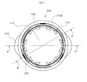
- FIG. 2 is a plane view showing the closure according to the present invention.
- FIG. 3 is a sectional view taken along the line A-A of FIG. 2 ;
- FIG. 4 is a sectional view taken along the line B-B of FIG. 2 ;
- FIGS. 5 and 6 are sectional views illustrating an opening procedure of the closure according to the present invention.
- FIGS. 7 to 10 are views illustrating exemplary modifications of a locking protrusion employed in the closure according to the present invention.
- FIGS. 11 to 13 show another embodiment of the closure according to the present invention.
- FIGS. 14 to 16 show still another embodiment of the closure according to the present invention.
- FIG. 17 shows another embodiment of the closure according to the present invention.
- a closure according to the present invention may be made of a resin material as a whole by an injection molding.
- the closure includes a sealing portion 110 assembled to surround an aperture of a container for airtightness, and a cover portion 120 assembled to an outside of the sealing portion 110 to be vertically movable with respect to the sealing portion 110 .
- a lower end of the sealing portion 110 is connected to an upper end of the cover portion 120 by means of a coupling band 130 shaped as a thin strip, and the coupling band is so thin that the coupling band may be folded.
- the sealing portion 110 has a plurality of locking protrusions 112 which are configured to be rotationally symmetrical so that the locking protrusions 112 may be fixed to a locking flange formed on the container.
- the number of the locking protrusions 112 may be suitably determined in consideration of the size of the closure, the degree of airtightness, etc.
- Each locking protrusion 112 is connected to a hinge 111 extending from a lower rim of the scaling portion 110 , and configured to protrude inwards.
- the hinge 111 is thinner in comparison to its locking protrusion 112 so each locking protrusion 112 may be rotated about its corresponding hinge 111 served as the rotational axis.
- Each locking protrusion 112 may have a groove 112 a which is inwardly concaved at a lower end of the locking protrusion, wherein a fixing protrusion 121 formed on an inside of the cover portion 120 is supported by the groove 112 a.
- the cover portion 120 may have a gripping protrusion 122 which protrudes outwards at a lower end of an outer circumferential surface of the cover portion 120 so that a user may easily grip the cover portion 120 upon the opening or closing operation of the closure.
- a gripping protrusion 122 which protrudes outwards at a lower end of an outer circumferential surface of the cover portion 120 so that a user may easily grip the cover portion 120 upon the opening or closing operation of the closure.
- two gripping protrusions may be located to be opposite to each other.
- FIG. 1 shows a state in which the sealing portion is entirely withdrawn from the cover portion, for the purpose of illustrating the entire configuration of the closure according to the present invention.
- the opening or closing operation of the closure may be performed while the sealing portion has been inserted into the cover portion, as will be explained in detail below with reference to other drawings.
- each locking protrusion 112 provided at the lower end of the sealing portion 110 are fixed to the locking flange formed on the container, and each locking protrusion 112 preferably has a concavely curved surface 112 b which would face the locking flange of the container, so that the locking protrusions 112 may be easily elastically deformed when the locking protrusions 112 are fixed to or released from the locking flange.
- FIG. 3 shows a state in which the closure is assembled to a container so that the closure comes into a closed state, wherein the locking protrusions 112 at the lower end of the sealing portion 110 are locked to the locking flange 210 of the container 200 , so the container may maintain its airtight state.
- the upper end of the sealing portion 110 coincides with the upper end of the cover portion 120 , so that the upper end of the sealing portion 110 is flush with the upper end of the cover portion 120 .
- Each fixing protrusion 121 of the cover portion 120 which is located outside the sealing portion 110 is seated into its corresponding groove II 2 a at the lower end of its corresponding locking protrusion 112 , so that all the locking protrusions 112 may not be widened outwards but firmly fixed to the locking flange 210 of the container 200 .
- each locking protrusion 112 is composed of an inclined surface 112 c , so that the inclined surface 112 c prevents each locking protrusion 112 from being locked by the locking flange 210 of the container while allowing the closure to be assembled.
- a rib 113 may be additionally formed on a lower surface of the sealing portion 110 so that the rib 113 may be inserted into the aperture of the container to increase the airtight state.
- the cover portion 120 is fittingly assembled to an outside of the sealing portion 110 so that the cover portion 120 may be moved upwards and downwards with respect to the sealing portion 110 , and the upward and downward operation between the sealing portion 110 and the cover portion 120 allows the closure to be opened or closed.
- a gap between the cover portion 120 and the sealing portion 110 is configured to be minimized as long as the cover portion 120 and the sealing portion 110 can be easily moved upwards and downwards with respect to each other.
- the coupling band 130 shaped as a thin strip is provided between the upper end of the cover portion 120 and the lower end of the sealing portion 110 , so that the cover portion 120 and the sealing portion 110 are connected to each other to be rolled into one.
- the coupling band is so thin that the coupling band 130 may be folded without disturbing the relative upward and downward movement between the cover portion and the sealing portion.
- both the cover portion 120 and the sealing portion 110 should be moved upwards in a state that the locking protrusions 112 have been supported by the fixing protrusions 121 .
- the locking protrusions 112 may not be easily separated from the locking flange 210 .
- the closure may not be opened.
- the closure may be opened only through its normal opening manipulation in which both the sealing portion and the cover portion are simultaneously manipulated as explained above.
- the closure according to the present invention serves as a safe closure which may be opened only through the normal opening manipulation of the closure as explained above.
- FIG. 6 shows a state in which the closure is opened, wherein each fixing protrusion 121 is located outside its corresponding hinge 111 . At this time, the upper end of the sealing portion 110 is located below the upper end of the cover portion 120 .
- the closure may be assembled to the container by pressing the closure over the container.
- each locking protrusion 112 moves over the locking flange 210 of the container to be fixed thereto.
- the cover portion 120 is moved downwards, and each fixing protrusion 121 is inserted into its corresponding groove 112 a of the locking protrusion 112 .
- each fixing protrusion 121 supports the locking protrusion 112 to prevent each locking protrusion 112 from being widened outwards, so that the container may be closed (see FIG. 5 ).
- FIGS. 7 to 10 show exemplary modifications of the locking protrusion which may be employed in the closure according to the present invention.
- FIG. 7 is an enlarged view showing a portion of a locking protrusion shown in FIG. 3 .
- the closure may be opened.
- the fixing protrusion 121 supporting the locking protrusion 112 moves upwards from the groove 112 a of the locking protrusion 112 , so that the fixing protrusion 121 may be separated from the groove 112 a .
- the fixing protrusion 121 and the locking protrusion 112 are compressed and elastically deformed.
- FIG. 8 is a graph for briefly illustrating a relation between the manipulating force F and the vertical displacement d between the cover portion and the sealing portion while the closure having the locking protrusion as shown in FIG. 7 is opened.
- a user needs a larger manipulating force F 1 up to the vertical displacement d 1 in order to open the closure.
- the manipulating force required for opening the closure may be determined by depending on the size of the fixing protrusion (the degree of protrusion) and the depth of the groove of the locking protrusion, etc., and therefore the manipulating force may be selected in accordance with the usage of the closure. For example, if the content of the container has a larger inner pressure like carbonated beverages, the closure is preferably designed not to be easily opened. In this case, the size of the fixing protrusion and the depth of the groove of the locking protrusion, etc. may be selected to require a larger manipulating force. Otherwise, the number of the fixing protrusions and the number of the locking protrusions in the closure may be increased.
- FIG. 9 shows one exemplary modification of the locking protrusion which may be employed in the closure according to the present invention.
- the locking protrusion 112 may have an inclined surface 112 d which is inclined with respect to a vertical direction at the lower end of the locking protrusion 112 , wherein the fixing protrusion 121 is supported by the inclined surface 112 d.
- FIG. 10 is a graph for briefly illustrating a relation between the manipulating force F and the vertical displacement d between the cover portion and the sealing portion while the closure having the locking protrusion as shown in FIG. 9 is opened.
- the fixing protrusion 121 is moved along the inclined surface of the locking protrusion 112 during the opening procedure, a user may open the closure with a relatively smaller manipulating force F 2 up to the vertical displacement d 1 which correspond to a border line of the inclined surface, in comparison to the exemplary modification shown in FIG. 7 .
- the magnitude of the manipulating force required for opening the closure may be varied depending on the shape of the locking protrusion, and therefore the manipulating force may be selected in accordance with the usage of the closure.
- the container may be designed to be easily opened or closed just with a relatively smaller manipulating force as shown in the modification of FIG. 9 .
- the closure may be selected to require a larger manipulating force as shown in the modification of FIG. 7 .
- the magnitude of the manipulating force required for opening the closure may be varied by changing the shape of the locking protrusion with reference to FIGS. 7 and 9 .
- the magnitude of the manipulating force required for opening the closure may be set in various ways by changing the size and/or the shape of the fixing protrusion.
- FIGS. 11 to 13 show other embodiments of the closure according to the present invention.
- a lever protrusion 114 which protrudes upwards from the upper end of the locking protrusion 112 may be additionally provided.
- two lever protrusions 114 protrude upwards from upper ends of both sides of the locking protrusion 112 adjacent to the hinge 111 .
- each lever protrusion 114 may prevent any interference between the locking protrusion and the locking flange of the container during the reassembling process of the opened closure to the container, so that the closure may be easily reassembled to the container without any inconvenience.
- FIG. 6 shows that the locking protrusion 112 should not be folded inwards after the closure is opened. If the locking protrusion 112 is folded inwards, the locking protrusion 112 might be locked by the locking flange 210 of the container during the reassembling process of the opened closure, so the closure might not be closed.
- the lever protrusion 114 allows the locking protrusion 112 to be permanently widened outwards after the closure is opened, so that the lever protrusion 114 may prevent any interference between the locking protrusion and the locking flange of the container during the reassembling process of the closure to the container, thereby preventing the closure from being incorrectly reassembled to the container.
- FIG. 12 shows that after the opening of the closure through the same procedure as explained above, the fixing protrusion 121 is located near the hinge so that the fixing protrusion 121 may allow the lever protrusion 114 to be pushed inwards and the locking protrusion 112 connected to the hinge 11 l may be widened outwards.
- the locking flange 210 of the container is always in contact with the inclined surface 112 c in the lower end of the locking protrusion 112 during the reassembling process of the opened closure, so that the closure may be easily assembled to the container.
- FIG. 13 shows an exemplary modification of the lever protrusion employed in the closure according to the present invention, wherein one lever protrusion 314 may protrude upward near the center of a locking protrusion 312 which is connected by two hinges 311 .
- a groove 312 a into which the fixing protrusion may be inserted is formed near the lower end of the locking protrusion 312 to which the lever protrusion 314 is located.
- the opening or closing procedure of the closure is identical to the embodiments as described above.
- the sealing portion is denoted by the reference number 310 and the cover portion is denoted by the reference number 320 .
- FIGS. 14 to 16 show still other embodiments of the closure according to the present invention.
- At least two guide bars 140 may be additionally fixed to the lower rim of the sealing portion 110 in the vertical downward direction so that lower ends of the guide bars 140 may be brought into contact with an inner circumferential surface of the cover portion 120 .
- FIG. 14 shows an appearance of the closure manufactured by the injection molding as shown in FIG. 1 .
- the sealing portion 110 is located above. However, if the sealing portion 110 is coupled with the container to close the closure as explained above, the upper end of the sealing portion 110 is flush with the upper end of the cover portion 120 (see FIG. 3 ).
- the sealing portion and the cover portion are connected to each other by means of only the thin coupling band.
- the weakness of the thin coupling band may cause the coupling band to be easily torn or damaged through the handling or transport procedure of the closure until the closure manufactured by the injection molding is assembled to the container.
- the guide bars provided in the closure according to the present invention serve to prevent the coupling band from being damaged during the handling procedure of the closure until the closure manufactured as described above is assembled to the container and then to guide the relative upward and downward movement between the sealing portion and the cover portion after the closure is assembled to the container.
- an upper end 140 a of the guide bar 140 fixed to the sealing portion 110 may be so thick that the upper end 140 a may be firmly fixed to the sealing portion 110 , while a lower end 140 b of the guide bar 140 fixed to the inner circumferential surface of the upper end of the cover portion 120 may be so thin that the lower end 140 b may be weakly connected to the upper end of the cover portion 120 in comparison to the upper end 140 a.
- the sealing portion 110 may be moved downwards and assembled to the container while the connection between the lower end 140 b of the guide bar 140 and the cover portion 120 is broken down.
- the guide bar 140 may be moved vertically along with the sealing portion 110 . Since the guide bar 140 is moved along the inner wall of the cover portion 120 , the guide bar 140 makes up for a gap between the sealing portion and the cover portion, so that the guide bar 140 may perform the guiding function for facilitating the upward and downward movement of the sealing portion and the cover portion.
- FIG. 17 shows a still further embodiment of the closure according to the present invention.
- the former embodiments illustrate that the sealing portion and the cover portion are connected to each other by means of the coupling band, the sealing portion and the cover portion need not to be connected by means of the coupling band in this embodiment.
- an auxiliary band thinly connected between the cover portion and the coupling band may be additionally provided so that the auxiliary band may be broken down when the closure is initially opened by applying a manipulating force over a certain level.
- a user may check whether the contents in the container have been already used or not by inspecting whether the auxiliary band is broken.
Landscapes
- Engineering & Computer Science (AREA)
- Mechanical Engineering (AREA)
- Closures For Containers (AREA)
Applications Claiming Priority (3)
| Application Number | Priority Date | Filing Date | Title |
|---|---|---|---|
| KR1020090055409A KR101121860B1 (ko) | 2009-06-22 | 2009-06-22 | 마개 및 이 마개를 갖는 용기 |
| KR10-2009-0055409 | 2009-06-22 | ||
| PCT/KR2010/003957 WO2010151009A2 (ko) | 2009-06-22 | 2010-06-18 | 마개 및 이 마개를 갖는 용기 |
Publications (2)
| Publication Number | Publication Date |
|---|---|
| US20120103993A1 US20120103993A1 (en) | 2012-05-03 |
| US8919595B2 true US8919595B2 (en) | 2014-12-30 |
Family
ID=43387013
Family Applications (1)
| Application Number | Title | Priority Date | Filing Date |
|---|---|---|---|
| US13/379,423 Active 2030-06-28 US8919595B2 (en) | 2009-06-22 | 2010-06-18 | Closure and container having the same closure |
Country Status (10)
| Country | Link |
|---|---|
| US (1) | US8919595B2 (pl) |
| EP (1) | EP2447180B1 (pl) |
| JP (1) | JP5607151B2 (pl) |
| KR (1) | KR101121860B1 (pl) |
| CN (1) | CN102803089B (pl) |
| ES (1) | ES2523352T3 (pl) |
| MY (1) | MY155490A (pl) |
| PL (1) | PL2447180T3 (pl) |
| TW (1) | TWI454410B (pl) |
| WO (1) | WO2010151009A2 (pl) |
Cited By (1)
| Publication number | Priority date | Publication date | Assignee | Title |
|---|---|---|---|---|
| US11261009B2 (en) * | 2018-09-24 | 2022-03-01 | Albea Services | Removable cap for a dispensing bottle |
Families Citing this family (9)
| Publication number | Priority date | Publication date | Assignee | Title |
|---|---|---|---|---|
| JP6253407B2 (ja) * | 2013-12-28 | 2017-12-27 | 日本クロージャー株式会社 | 易開封型打栓式キャップおよびその打栓方法 |
| JP6322446B2 (ja) * | 2014-03-04 | 2018-05-09 | 日本クロージャー株式会社 | 合成樹脂製容器蓋 |
| JP6468793B2 (ja) | 2014-10-21 | 2019-02-13 | 日本クロージャー株式会社 | 合成樹脂製容器蓋 |
| JP6438824B2 (ja) * | 2015-03-31 | 2018-12-19 | 日本クロージャー株式会社 | 合成樹脂製容器蓋 |
| JP6503215B2 (ja) * | 2015-03-31 | 2019-04-17 | 日本クロージャー株式会社 | 容器蓋を容器の口頸部に装着する方法及び装置 |
| JP6503238B2 (ja) * | 2015-06-22 | 2019-04-17 | 日本クロージャー株式会社 | 合成樹脂製容器蓋 |
| CN106672423B (zh) * | 2016-12-14 | 2018-08-10 | 林颖 | 瓶盖连接结构及水瓶 |
| FR3098505B1 (fr) * | 2019-07-09 | 2021-06-04 | A Raymond Et Cie | coiffe de verrouillage sécable pour récipient à col |
| KR102096794B1 (ko) * | 2019-11-18 | 2020-04-03 | 채동석 | 마개와 용기의 원터치 개폐 구조 |
Citations (19)
| Publication number | Priority date | Publication date | Assignee | Title |
|---|---|---|---|---|
| US3952901A (en) * | 1974-07-02 | 1976-04-27 | Dairy Cap Corporation | Tamper-proof overcap construction |
| US4359166A (en) * | 1979-11-07 | 1982-11-16 | Createchnic Patent Ag | Container closure cap |
| US4366921A (en) * | 1981-09-28 | 1983-01-04 | Ethyl Products Company | Child-resistant closure device |
| US4519514A (en) | 1984-03-20 | 1985-05-28 | Robert Linkletter Associates, Inc. | Tamper resistant and tamper evident closures |
| US5314084A (en) * | 1992-08-21 | 1994-05-24 | The West Company, Incorporated | Two piece all plastic seal |
| JP2563125B2 (ja) | 1987-05-07 | 1996-12-11 | ポール・ゲゼルシヤフト・ミト・ベシユレンクテル・ハフツング・ウント・コンパニー・コマンデイトゲゼルシヤフト | 注入びんと輸注びん用の閉鎖キヤツプ |
| JPH09501375A (ja) | 1993-05-06 | 1997-02-10 | ファルマ−グミ ヴィンメル ヴェスト ゲゼルシャフト ミット ベシュレンクテル ハフツング | 瓶を閉鎖するための閉鎖キャップ |
| US5788100A (en) * | 1993-10-27 | 1998-08-04 | Sturk; Ron | Closure with two position lock ring |
| US5927529A (en) * | 1996-08-19 | 1999-07-27 | Magenta Corporation | Child resistant container |
| US5957314A (en) * | 1996-04-09 | 1999-09-28 | Taisei Kako Co., Ltd. | Crown caps for drug containers |
| US6158604A (en) * | 1996-11-15 | 2000-12-12 | Constancio Larguia, Sr. | Container safety cap with safety seal and combination of such a cap with a container |
| US6328174B1 (en) * | 1996-11-25 | 2001-12-11 | Diseno Industrial Mago. S.L. | Sealed closure cap |
| KR200394215Y1 (ko) | 2005-06-03 | 2005-09-01 | 장재수 | 강력 접착제 보관용기 |
| WO2007148916A1 (en) * | 2006-06-21 | 2007-12-27 | Dong-Seuk Chae | Closure and container having the same |
| US7401706B2 (en) * | 2004-09-27 | 2008-07-22 | Rexam Prescription Products Inc. | Closure and package having child-resistant and non-child-resistant modes of operation |
| US20090139953A1 (en) * | 2007-10-18 | 2009-06-04 | Daniel Py | Container having a closure and removable resealable stopper for sealing a substance therein, and related method |
| US7845505B2 (en) * | 2003-06-03 | 2010-12-07 | Taisei Kako Co., Ltd. | Container cap |
| US7878354B2 (en) * | 2003-07-25 | 2011-02-01 | Dong-Seuk Chae | One touch-type stopper and a container having the same |
| US8225949B2 (en) * | 2005-11-30 | 2012-07-24 | Biocorp Recherche Et Developpement | Plug device for a container and container provided with one such device |
Family Cites Families (7)
| Publication number | Priority date | Publication date | Assignee | Title |
|---|---|---|---|---|
| FR2352718A1 (fr) * | 1976-05-26 | 1977-12-23 | Probst Edgar | Dispositif de fermeture de bouteilles comportant un capuchon et un anneau qui peut coulisser d'une position de fermeture a une position de deblocage |
| US4364483A (en) * | 1981-02-02 | 1982-12-21 | Erich Golde | Child proof screw cap |
| JPS5993660A (ja) * | 1982-11-22 | 1984-05-30 | 株式会社 大井製作所 | ワンタツチ容器蓋 |
| US4516684A (en) * | 1984-04-10 | 1985-05-14 | Continental Packaging Company, Inc. | Resealable closure |
| KR100575259B1 (ko) | 2003-07-25 | 2006-04-28 | 채동석 | 원터치식 마개 및 이 마개가 구비된 용기 |
| NZ547489A (en) * | 2003-11-25 | 2010-04-30 | Nci Holdings Pty Ltd | A reusable closure for a container with a locking ring that engadges securing lugs to clamp the lid to the container |
| KR200385497Y1 (ko) | 2005-03-11 | 2005-05-27 | 채동석 | 마개 및 이 마개가 구비된 용기 |
-
2009
- 2009-06-22 KR KR1020090055409A patent/KR101121860B1/ko active Active
-
2010
- 2010-06-18 MY MYPI2011006216A patent/MY155490A/en unknown
- 2010-06-18 PL PL10792291T patent/PL2447180T3/pl unknown
- 2010-06-18 JP JP2012515992A patent/JP5607151B2/ja active Active
- 2010-06-18 CN CN201080027445.9A patent/CN102803089B/zh active Active
- 2010-06-18 EP EP10792291.6A patent/EP2447180B1/en active Active
- 2010-06-18 WO PCT/KR2010/003957 patent/WO2010151009A2/ko not_active Ceased
- 2010-06-18 US US13/379,423 patent/US8919595B2/en active Active
- 2010-06-18 ES ES10792291.6T patent/ES2523352T3/es active Active
- 2010-06-21 TW TW099120034A patent/TWI454410B/zh not_active IP Right Cessation
Patent Citations (21)
| Publication number | Priority date | Publication date | Assignee | Title |
|---|---|---|---|---|
| US3952901A (en) * | 1974-07-02 | 1976-04-27 | Dairy Cap Corporation | Tamper-proof overcap construction |
| US4359166A (en) * | 1979-11-07 | 1982-11-16 | Createchnic Patent Ag | Container closure cap |
| US4366921A (en) * | 1981-09-28 | 1983-01-04 | Ethyl Products Company | Child-resistant closure device |
| US4519514A (en) | 1984-03-20 | 1985-05-28 | Robert Linkletter Associates, Inc. | Tamper resistant and tamper evident closures |
| JP2563125B2 (ja) | 1987-05-07 | 1996-12-11 | ポール・ゲゼルシヤフト・ミト・ベシユレンクテル・ハフツング・ウント・コンパニー・コマンデイトゲゼルシヤフト | 注入びんと輸注びん用の閉鎖キヤツプ |
| US5314084A (en) * | 1992-08-21 | 1994-05-24 | The West Company, Incorporated | Two piece all plastic seal |
| JPH09501375A (ja) | 1993-05-06 | 1997-02-10 | ファルマ−グミ ヴィンメル ヴェスト ゲゼルシャフト ミット ベシュレンクテル ハフツング | 瓶を閉鎖するための閉鎖キャップ |
| US5678718A (en) * | 1993-05-06 | 1997-10-21 | The West Company Deutschland Gmbh | Bottle cap |
| US5788100A (en) * | 1993-10-27 | 1998-08-04 | Sturk; Ron | Closure with two position lock ring |
| US5957314A (en) * | 1996-04-09 | 1999-09-28 | Taisei Kako Co., Ltd. | Crown caps for drug containers |
| US5927529A (en) * | 1996-08-19 | 1999-07-27 | Magenta Corporation | Child resistant container |
| US6158604A (en) * | 1996-11-15 | 2000-12-12 | Constancio Larguia, Sr. | Container safety cap with safety seal and combination of such a cap with a container |
| US6328174B1 (en) * | 1996-11-25 | 2001-12-11 | Diseno Industrial Mago. S.L. | Sealed closure cap |
| US7845505B2 (en) * | 2003-06-03 | 2010-12-07 | Taisei Kako Co., Ltd. | Container cap |
| US7878354B2 (en) * | 2003-07-25 | 2011-02-01 | Dong-Seuk Chae | One touch-type stopper and a container having the same |
| US7401706B2 (en) * | 2004-09-27 | 2008-07-22 | Rexam Prescription Products Inc. | Closure and package having child-resistant and non-child-resistant modes of operation |
| KR200394215Y1 (ko) | 2005-06-03 | 2005-09-01 | 장재수 | 강력 접착제 보관용기 |
| US8225949B2 (en) * | 2005-11-30 | 2012-07-24 | Biocorp Recherche Et Developpement | Plug device for a container and container provided with one such device |
| WO2007148916A1 (en) * | 2006-06-21 | 2007-12-27 | Dong-Seuk Chae | Closure and container having the same |
| US20100243599A1 (en) * | 2006-06-21 | 2010-09-30 | Dong-Seuk Chae | Closure and container having the same |
| US20090139953A1 (en) * | 2007-10-18 | 2009-06-04 | Daniel Py | Container having a closure and removable resealable stopper for sealing a substance therein, and related method |
Non-Patent Citations (1)
| Title |
|---|
| International Search Report for International Application No. PCT/KR2010/003957. |
Cited By (1)
| Publication number | Priority date | Publication date | Assignee | Title |
|---|---|---|---|---|
| US11261009B2 (en) * | 2018-09-24 | 2022-03-01 | Albea Services | Removable cap for a dispensing bottle |
Also Published As
| Publication number | Publication date |
|---|---|
| MY155490A (en) | 2015-10-30 |
| ES2523352T3 (es) | 2014-11-25 |
| EP2447180B1 (en) | 2014-08-13 |
| PL2447180T3 (pl) | 2015-01-30 |
| TWI454410B (zh) | 2014-10-01 |
| JP5607151B2 (ja) | 2014-10-15 |
| JP2012530654A (ja) | 2012-12-06 |
| KR20100137135A (ko) | 2010-12-30 |
| CN102803089A (zh) | 2012-11-28 |
| US20120103993A1 (en) | 2012-05-03 |
| KR101121860B1 (ko) | 2012-03-20 |
| CN102803089B (zh) | 2015-02-11 |
| WO2010151009A3 (ko) | 2011-03-31 |
| TW201119914A (en) | 2011-06-16 |
| EP2447180A2 (en) | 2012-05-02 |
| EP2447180A4 (en) | 2013-07-03 |
| WO2010151009A2 (ko) | 2010-12-29 |
Similar Documents
| Publication | Publication Date | Title |
|---|---|---|
| US8919595B2 (en) | Closure and container having the same closure | |
| EP2298659B1 (en) | Connecting structure | |
| US8567621B2 (en) | Closure and container having the same | |
| CN1934028B (zh) | 饮料配发器 | |
| KR20170038022A (ko) | 컨테이너와 클로저 및 그것의 제조 | |
| KR102118504B1 (ko) | 캔커버 | |
| US12319474B2 (en) | Plastic container and method of manufacture | |
| KR200446283Y1 (ko) | 세로접이선이 구비된 용기 | |
| JP2008222249A (ja) | キャップおよび閉止装置ならびに飲料入り閉止装置 | |
| KR20190001483U (ko) | 내용물의 보관 및 음용이 가능한 다단 용기 | |
| KR101229152B1 (ko) | 밀폐수단을 구비한 음료용기 뚜껑 | |
| JPS5845241Y2 (ja) | 瓶蓋 | |
| KR102096794B1 (ko) | 마개와 용기의 원터치 개폐 구조 | |
| KR200385497Y1 (ko) | 마개 및 이 마개가 구비된 용기 | |
| KR200354814Y1 (ko) | 두 종류의 내용물을 혼합할 수 있는 이중용기 | |
| KR200422328Y1 (ko) | 에어배출 누름버튼과 에어공 이중 밀폐구조를 구비한음료용기 | |
| KR200390444Y1 (ko) | 2단 밀폐구조를 음료용기 뚜껑 | |
| CN216003702U (zh) | 瓶盖及具有其的饮料瓶 | |
| KR200395480Y1 (ko) | 용기용 밀폐덮개 | |
| KR200207835Y1 (ko) | 용기와 뚜껑의 결합구조 | |
| KR200184536Y1 (ko) | 화물고정용 에어백의 마개 | |
| US20110095023A1 (en) | Integrally formed attachment cap with lid opened by single push | |
| KR920003427Y1 (ko) | 오프너 없이 개봉하는 병마개 | |
| KR200233050Y1 (ko) | 이중 개폐마개를 가진 용기 | |
| KR20220001406U (ko) | 용기 |
Legal Events
| Date | Code | Title | Description |
|---|---|---|---|
| STCF | Information on status: patent grant |
Free format text: PATENTED CASE |
|
| MAFP | Maintenance fee payment |
Free format text: PAYMENT OF MAINTENANCE FEE, 4TH YR, SMALL ENTITY (ORIGINAL EVENT CODE: M2551) Year of fee payment: 4 |
|
| MAFP | Maintenance fee payment |
Free format text: PAYMENT OF MAINTENANCE FEE, 8TH YR, SMALL ENTITY (ORIGINAL EVENT CODE: M2552); ENTITY STATUS OF PATENT OWNER: SMALL ENTITY Year of fee payment: 8 |