US8910742B2 - Electric power-steering apparatus - Google Patents
Electric power-steering apparatus Download PDFInfo
- Publication number
- US8910742B2 US8910742B2 US14/009,358 US201214009358A US8910742B2 US 8910742 B2 US8910742 B2 US 8910742B2 US 201214009358 A US201214009358 A US 201214009358A US 8910742 B2 US8910742 B2 US 8910742B2
- Authority
- US
- United States
- Prior art keywords
- connector
- section
- steering
- electric power
- steering apparatus
- Prior art date
- Legal status (The legal status is an assumption and is not a legal conclusion. Google has not performed a legal analysis and makes no representation as to the accuracy of the status listed.)
- Active
Links
Images


Classifications
-
- B—PERFORMING OPERATIONS; TRANSPORTING
- B62—LAND VEHICLES FOR TRAVELLING OTHERWISE THAN ON RAILS
- B62D—MOTOR VEHICLES; TRAILERS
- B62D5/00—Power-assisted or power-driven steering
- B62D5/04—Power-assisted or power-driven steering electrical, e.g. using an electric servo-motor connected to, or forming part of, the steering gear
- B62D5/0403—Power-assisted or power-driven steering electrical, e.g. using an electric servo-motor connected to, or forming part of, the steering gear characterised by constructional features, e.g. common housing for motor and gear box
- B62D5/0406—Power-assisted or power-driven steering electrical, e.g. using an electric servo-motor connected to, or forming part of, the steering gear characterised by constructional features, e.g. common housing for motor and gear box including housing for electronic control unit
Definitions
- the present invention relates to a steering apparatus for an automobile, and more particularly to an electric power-steering apparatus that uses an electric motor as an auxiliary power source, and is able to reduce the force necessary for operating a steering wheel.
- FIG. 10 illustrates an example of a conventional electric power-steering apparatus.
- the directions in the following explanation are all directions when the steering apparatus is assembled in a vehicle.
- a steering shaft 2 is supported by way of a rolling bearing (not illustrated in the figure) on the inside of a cylindrical steering column 1 that is supported by the vehicle body so as to be able to freely rotate.
- a steering wheel 3 is fastened to the portion on the rear end section of the steering shaft 2 that protrudes from the opening section on the rear end of the steering column 1 .
- the portion on the front end section of the steering shaft 2 that protrudes from the opening on the front end of the steering column 1 is connected to the rear end section of the intermediate shaft 5 by way of a universal joint 4 a .
- the front end section of the intermediate shaft 5 is connected to the input shaft (pinion shaft) 7 of the steering gear unit 6 by way of another universal joint 4 b.
- FIG. 11 illustrates an example of specific structure of the major parts of an electric power-steering apparatus that is disclosed in JP 9-20252 (A).
- a cylindrical transmission shaft 11 is supported inside a housing 10 that is fastened to the front end section of the steering column 1 a so as to be able to rotate, and the rear end section of this transmission shaft 11 and the front end section of the steering shaft 2 a are connected by way of a torsion bar 12 so as to be able to transmit torque.
- a worm wheel 13 that is fastened to the outer circumferential surface of the middle section of the transmission shaft 11 is made to engage with a worm 15 that is fastened to the output shaft 14 of an electric motor 9 a so as to be able to apply auxiliary power from the electric motor 9 a to the transmission shaft 11 .
- a torque sensor 16 is arranged around the transmission shaft 11 .
- a harness 19 is connected by way of a connector 18 to the circuit board 17 that is connected to this torque sensor 16 , and measurement values that indicate the direction and size of the torque that are outputted from this torque sensor 16 are inputted to a controller (ECU) (not illustrated in the figure).
- the housing 10 is composed of a worm wheel housing section 48 , a torque sensor housing section 49 , a circuit board housing section 50 and a worm housing section 51 .
- the worm wheel housing section 48 is an approximate circular disk shape that is arranged so as to be concentric with the steering column 1 a , and houses the worm wheel 13 on the inside thereof.
- the torque sensor housing section 49 is provided adjacent to the rear side of the worm wheel housing section 48 , and having a smaller diameter than the worm wheel housing section 48 , houses the torque sensor 16 on the inside thereof.
- the circuit board housing section 50 is provided above the torque sensor housing section 49 , and houses the circuit board 17 on the inside thereof.
- the worm housing section 51 has an approximate cylindrical shape that is arranged in a twisted position with respect to the steering shaft 2 a , and houses the worm 15 on the inside thereof.
- the connector 18 is located above the circuit board housing section 50 .
- the worm wheel housing section 48 and the torque sensor housing section 49 cover the worm wheel 13 and the torque sensor 16 with minimum volume. Therefore, the outer circumferential surfaces of both the worm wheel housing section 48 and the torque sensor housing section 49 are formed into a circular shape along the shape of the worm wheel 13 and the torque sensor 16 .
- the connector 18 is placed on the upward side of the housing 10 (top side in FIG. 11 ), and is arranged in a narrow empty space between the housing 10 and a member on the vehicle side such as a steering support. Furthermore, the work of connecting the harness 19 to the connector 18 is normally performed from the driver seat side, so for the worker performing this connection work, the connector 18 is hidden behind the housing 10 . Therefore, performing the work of connecting the harness 19 to the connector 18 after the electric power-steering apparatus has been assembled in the vehicle is inferior in work characteristics, and it causes an increase in cost.
- connection work before the electric power-steering apparatus has been assembled in the vehicle.
- one group of electrical components that are electrically connected by way of a connector is arranged on both the electric power-steering apparatus side and the vehicle side, in order to perform the connection work before assembly, the length of the harness that connects to the connector must be sufficiently longer than the originally required length. Therefore, together with causing costs and weight to increase, the harness gets in the way, and there is a possibility that the ease of performing the work of assembling the electric power-steering apparatus will decrease.
- the object of the present invention is to achieve structure of an electric power-steering apparatus that is capable of both preventing damage to connectors used for supplying power to electrical components, and to improve the ease of the work required for connecting connectors.
- the electric power-steering apparatus of the present invention is basically the same as a conventional electric power-steering apparatus, and comprises: a cylindrical steering column that is supported by a vehicle body; a steering shaft that is supported on the inside of the steering column so as to be able to rotate freely, and that is rotated by a steering wheel that is fastened to the rear end section thereof; an electrical component that is used for applying auxiliary power in the same direction as the force applied from the steering wheel to the steering shaft or to a member that displaces as the steering shaft rotates; a connector for supplying electric power to the electrical component; and a housing that is fastened to the front end section of the steering column and comprises; a worm wheel housing section that has an approximate circular disk shape, that is arranged so as to be concentric with the steering column, and that houses a worm wheel inside thereof; and a torque sensor housing section that is provided adjacent to the rear side of the worm wheel housing section, that has a smaller diameter than the worm wheel housing section and that houses a torque sensor inside thereof.
- the electric power-steering apparatus of the present invention is characterized by the installation location of the connector.
- the connector is installed in a portion that is located below the steering column or the torque sensor housing section when assembled in the vehicle, and that is above and separated from a flat plane assuming that the electric power-steering apparatus is placed on the flat plane with a bottom surface of the steering column facing downward when assembled in the vehicle.
- the electric component means a component that is used for applying auxiliary power to the steering shaft or a member that displaces as the steering shaft rotates, however, it is not limited to a component that directly applies auxiliary power, but also includes a component that is indirectly used for applying auxiliary power. More specifically, the electric component is exemplified by an electric motor, a controller (ECU), a torque sensor, a rotation speed sensor and the like. Moreover, the connector means a part that is used for supplying electric power to the electrical component or is electrically connecting the electrical component to the other electrical component with connected to a harness or the like, for supplying power, supplying signals, for grounding and the like, however the use and the shape are not limited.
- a protective section is provided on the bottom surface of the steering column or a bottom surface of the worm wheel housing section and extends downward when assembled in the vehicle, and assuming that the electric power-steering apparatus is placed on the flat plane, a bottom end section of the protective section comes in contact with the flat plane.
- the width dimension of the protective section (dimension in the left-right direction of the vehicle) is greater than the width dimension of the connector.
- the connector is supported by this protective section.
- the protective section has an approximate L-shaped cross section, and this protective section covers the side section and part or all of the bottom section of the connector.
- the connector is a power supply connector (single power supply connector) for supplying electric power to an electric motor of the electric component, or is a combined connector (intentionally integrated with another connector) that includes this power supply connector.
- an electric power-steering apparatus can be achieved that is capable of both preventing damage to the connector, and improving workability of the work for connecting the connector.
- the connector when assembled in the vehicle, the connector is located in a portion below the steering column, or of the housing, in a portion that is located below the torque sensor housing section that has a smaller diameter than the worm wheel housing section and is adjacent to the rear side of this worm wheel housing section.
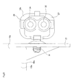
- FIG. 1 is a side view illustrating an electric power-steering apparatus of a first example of an embodiment of the present invention.
- FIG. 2 is a drawing of the electric power-steering apparatus illustrated in FIG. 1 , and illustrates the state as seen from the rear side of the vehicle.
- FIG. 3 is a drawing of the electric power-steering apparatus illustrated in FIG. 1 , and illustrates the state as seen from the front side of the vehicle.
- FIG. 4 is an enlarged view as seen from the right side in FIG. 1 (the rear side of the vehicle), and illustrates the state immediately before connecting the plug to the connector.
- FIG. 5 is a side view illustrating the electric power-steering apparatus illustrated in FIG. 1 with a support bracket and support plate omitted.
- FIG. 6 is a drawing similar to FIG. 4 , and illustrates an electric power-steering apparatus of a second example of an embodiment of the present invention.
- FIG. 7 is a perspective view illustrating an electric power-steering apparatus of a third example of an embodiment of the present invention.
- FIG. 8 is an enlarged view of the connector illustrated in FIG. 7 as seen from the plug insertion side.
- FIG. 9 is a side view illustrating an electric power-steering apparatus of a fourth example of an embodiment of the present invention.
- FIG. 10 is a partial cross-sectional view that illustrates an example of a conventional electric power-steering apparatus.
- FIG. 11 is a partial cross-sectional view that illustrates an example of the main parts of a conventional electric power-steering apparatus.
- FIG. 1 to FIG. 5 illustrate a first example of an embodiment of the present invention.
- Feature of this example are, together with devising an installation position for installing a connector 18 a used for providing power to a controller 20 , providing a protective wall section 21 for protecting the connector 18 a .
- the basic structure and function of the other parts are the same as in a conventional electric power-steering apparatus. Therefore, explanations of common parts are omitted or simplified, so that the explanation below centers on the features of this example.
- an electric motor (brushless motor) 9 b is used as an auxiliary power source for reducing the force necessary for operating a steering wheel 3 (see FIG. 10 ).
- the electric motor 9 b is supported on the top surface of a housing 10 a that is fastened to the front end section of an inner column 40 of a steering column 1 b in a state such that the output shaft is orthogonal with respect to the steering column 1 b , and is supported in an upright position.
- the output torque (auxiliary power) of the electric motor 9 b is applied to a steering shaft 2 b by way of a worm reduction gear that is provided in the housing 10 a and is composed of a worm 15 a and a worm wheel 13 a.
- the housing 10 a is made by casting an aluminum alloy for example, and comprises a worm wheel housing section 48 a , a torque sensor housing 49 a , a circuit board housing 50 a and a worm housing section 51 a .
- the worm wheel housing section 48 a has an approximate circular disk shape, is arranged so as to be concentric with the steering column 1 b , and houses a worm wheel 13 a therein.
- the torque sensor housing 49 a is provided so as to be adjacent to the rear side of the worm wheel housing section 48 a , has a smaller diameter than the worm wheel housing section 48 a , and houses a torque sensor 16 a that comprises a pair of detection coils therein.
- the circuit board housing section 50 a has a rectangular box shape, is provided below the torque sensor housing unit 49 a , and houses a circuit board 17 a that is connected to the torque sensor 16 a . Furthermore, the worm housing section 51 a has an approximate cylindrical shape, is arranged in a twisted position with respect to the steering column 1 b (up-down direction in FIG. 1 to FIG. 3 , and FIG. 5 ), and houses a worm 15 a therein.
- a case 22 having an approximate rectangular shape and made of synthetic resin or metal is located in the portion on the top surface of the housing 10 a that is adjacent to the electric motor 9 b , and this case 22 houses a controller (ECU) 20 for controlling the driving state of the electric motor 9 b therein.
- the controller 20 and the electric motor 9 b are connected by a motor harness 24
- the controller 20 and the circuit board 17 a are connected by a sensor harness 25 .
- the end sections (plugs) of the motor harness 24 and the sensor harness 25 are connected to the connectors (not illustrated in the figure) that are provided on the controller 20 , electric motor 9 b and circuit board 17 a , however, instead of a combination of a plug and connector, they can be directly connected using solder or the like.
- the controller 20 and the electric motor 9 b can be directly connected by a plurality of terminal fittings (not illustrated in the figure) without using a motor harness 24 .
- electric power that is supplied to the controller 20 which is an electrical component, from a battery (not illustrated in the figure) that is located in the engine room or the like, passes through an inverter circuit of the controller 20 and then is supplied to the electric motor 9 b .
- a power supply connector 26 is used for supplying power from the battery to the controller 20 .
- a large current of about 50 A to 80 A is required compared with the other electrical components, so in order to prevent fire and degradation over time and maintain fire resistance, a relatively large connector is used as the power-supply connector 26 .
- a single integrated connector (combined connector) 18 a is used for the power-supply connector 26 and a signal connector 27 that is used for performing communication with the in-vehicle network such as CAN, however, the power-supply connector 26 and the signal connector 27 , instead of being integrated, can be separately provided.
- these connectors are separately provided in this way, it is possible to devise the installation location for only the power-supply connector 26 so as to easily be made large in order to maintain reliability.
- a large part of the connector 18 a is made using synthetic resin.
- parts such as the controller 20 and the electric motor 9 b to which power is supplied by way of the controller 20 correspond to electrical components that are used for applying auxiliary power
- the connector 18 a corresponds to a connector used for supplying power to these electrical components.
- the installation position of the connector 18 a is devised. More specifically, the connector 18 a is installed in a portion (space) that is located on the rear side of the bottom end section (end section on the outer diameter side) of the worm wheel housing section 48 a and below the torque sensor housing section 29 a of a space located below the housing 10 a , when the electric power-steering apparatus is assembled in the vehicle (or when tilted in a horizontal state from the assembled state as illustrated in FIG. 1 ), and that is above and separated from a flat plane ⁇ , when the electric power-steering apparatus is placed on the flat plane ⁇ as indicated by the chain line in FIG. 1 with the bottom surface of the steering column facing downward as when assembled in the vehicle.
- the connector 18 a is supported by and fastened to a cover 23 that covers the bottom surface of the circuit board housing section 50 a by way of an installation plate 28 .
- This installation plate 28 is composed of a pair of connecting sections 29 that are provided on both end sections in the width direction (left-right direction of the vehicle) and a support section 30 having an approximate U-shaped cross section that is provided between these connecting sections 29 .
- the top surfaces of these connecting sections 29 are fastened to the bottom surface of the cover 23 by welding, screws, or some other fastening method.
- the connector 18 a is supported by and fastened to the bottom surface of the support section 30 using a fastening member 31 . In this state, part of this fastening member 31 is located in a space between the cover 23 and the support section 30 . With this kind of structure, the connector 18 a is located in the portion of the bottom side of the circuit board housing section 50 a of the portion located below the torque sensor housing section 49 a.
- a flat shaped protective wall section 21 is formed so as to extend downward from the bottom surface of the worm wheel housing section 48 a of the housing 10 a .
- the edge on the bottom end (edge of the tip end) of this protective wall section 21 is made to protrude sufficiently downward further than the bottom end section of the connector 18 a that is arranged as described above (located further away from the center axis of the steering column).
- the installation position of this connector 18 a taking into consideration the installation position of this connector 18 a , the position of the portion other than the protective wall section 21 that comes in contact with the flat plane ⁇ and the amount that protrudes downward (height dimension) thereof, the installation position of the protective wall section 21 and the downward protruding amount thereof are regulated so that the connector 18 a is located in a portion separated from and above the flat plane ⁇ .
- the electric power-steering apparatus is presumed to be placed on the flat plane ⁇ before assembled in the vehicle, the edge on the bottom end of the protective wall section 21 and the corners 47 on bottom surface of the rear end section of the side plates sections 33 on both sides of the support bracket 32 for supporting the middle section of the steering column 1 b by the vehicle come in contact with the flat plane ⁇ , and a gap 52 is formed between the flat plane ⁇ and the bottom end section of the connector 18 a .
- the width dimension of the protective wall section 21 (dimension in the left-right direction in FIG. 2 ) is larger than the width dimension of the connector 18 a .
- the dimensions in the forward-backward direction of the connector 18 a are regulated so that the connector 18 a does not protrude toward the rear more than the circuit board housing section 50 a.
- the power supply harness 36 that is connected to the battery, and the signal harness 37 that is connected to the in-vehicle network are connected to the connector 18 a using one plug (combined plug) 38 .
- An concave section is formed on the tip end surface of the plug 38 into which the tip end side half section of the connector 18 a can be inserted, and by inserting the tip end side half section of the connector 18 a into this concave section, the power supply harness 36 and the power cable 34 , as well as the signal harness 37 and the signal cable 35 are electrically connected.
- power flows to the controller 20 and the battery, and also to the controller 20 and in-vehicle network, completing the work (insertion) of connecting the plug 38 into the connector 18 a.
- the electric power-steering apparatus of this example comprises a telescopic mechanism, a tilt mechanism and a collapsing mechanism for lessening the impact that occurs during a so-called secondary collision.
- the steering column 1 b is constructed by combining an outer column 39 with an inner column 40 in a telescope shape so as to be able to extend and contract.
- the outer column 39 is supported by the support bracket 32 so as to be able to move in the forward-backward direction.
- the steering shaft 2 b is constructed by combining an outer shaft 41 and an inner shaft 42 with a spline fit and the like so as to be able to transmit torque and to be able to extend and contract.
- the top section of the front end section of the worm wheel housing section 48 a of the housing 10 a is supported by a support plate 43 made of metal plate that is fastened to the vehicle body by a tilt shaft so that pivoting displacement is possible.
- the outer column 39 is supported by the support bracket 32 so as to be move in the up-down direction.
- the support bracket 32 is supported by a support plate 43 using a pair of support capsules 45 and bolts (not illustrated in the figure) so as to be able to break away in the forward direction. Therefore, when a secondary collision occurs in which the driver collides with the steering wheel 3 (see FIG. 10 ), by the outer column 39 displacing (stroke) in the forward direction with respect to the inner column 40 , both support capsules 45 break away from the support bracket 32 , and the support bracket 32 moves together with the outer column 39 toward the front side (housing 10 a side) of the vehicle.
- the connector 18 a is such that it does not protrude further toward the rear side than the circuit board housing section 50 a , so the support bracket 32 is prevented from coming in contact with the connector 18 a . Therefore, the installation of this connector 18 a does not limit the amount of displacement in the forward direction of the steering wheel 3 during a secondary collision.
- the connector 18 a when assembled in the vehicle, the connector 18 a is located on the rear side of the bottom end section (end section on the outer diameter side) of the worm wheel housing section 48 a and below the torque sensor housing sections 49 . Therefore, for the worker who performs the connection work from the driver seat side, the connector 18 a is exposed in a relatively large space (legroom) further on the near side than the housing 10 a . Consequently, it becomes possible to easily perform the work of inserting the plug 38 into the connector 18 a and connecting the power supply harness 36 and the signal harness 37 . Particularly, in this example, it is possible to perform this work with one hand because this connecting work can be completed by inserting the plug 38 into the connector 18 a , so it is possible to improve the workability of the work for connecting the connector 18 a.
- the installation position of the connector 18 a and the installation position and protruding amount of the protective wall section 21 are regulated so that the edge on the bottom end of the protective wall section 21 and the corners 47 of the side plate sections 33 on both sides of the support bracket 32 come in contact with the flat plane ⁇ and so that a gap 52 is formed between the flat plane ⁇ and the connector 18 a .
- the electric power-steering apparatus of this example it is possible to both prevent damage to the connector 18 a and to improve workability of the work for connecting the connector 18 a .
- a power cable 34 and signal cable 35 come out from the connector 18 a in the width direction, so it is possible to prevent damage to these cables 34 , 35 due to the end sections of these cables 34 , 35 coming in contact with the floor surface.
- the amount of displacement in the forward direction of the steering wheel 3 during a secondary collision is not limited by the existence of the connector 18 a.
- FIG. 6 illustrates a second example of an embodiment of the present invention.
- the structure of installing the connector 18 a is different than in the first example of the embodiment.
- the installation plate 28 a for fastening the connector 18 a to the cover 23 that covers the bottom surface of the circuit board housing section 50 a is composed of a connecting section 29 a and a support section 30 a that has an L shaped cross section.
- This support section 30 a is pressure fitted into a locking hole or locking groove that is provided in a locking section 46 that is formed on the upper portion of the connector 18 a , and the connector 18 a is supported by the support section 30 a so as to be suspended.
- the work of installing the connector 18 a is simplified because there is no necessity of using the fastening member 31 that is used in the structure of the first example, and it is possible to reduce the number of parts and costs.
- the structure and functions of other parts are the same as in the first example.
- FIG. 7 and FIG. 8 illustrate a third example of an embodiment of the present invention.
- the position for installing the connector 18 a is different than in the first and second examples.
- the connector 18 a is directly supported by and fastened to the middle section in the up-down direction of the surface on the rear side of the protective wall section 21 .
- this example having this kind of structure it is possible to reduce the number of parts and reduce the accompanying costs by the amount of omitting the installation plates 28 , 28 a that were used in the first example and second example.
- the connector 18 a is fastened with the power supply connector 26 and the signal connector 27 of the connector 18 a arranged in the up-down direction, however it is also possible to arrange them in the forward-backward direction as in the first example and second example.
- the power supply connector 26 and the signal connector 27 in the up-down direction.
- FIG. 9 illustrates a fourth example of an embodiment of the present invention.
- the shape of the protective wall section 21 a is different than in the first example through third example.
- the protective wall section 21 a by extending the protective wall section 21 a toward the rear from the edge on the bottom end, the protective wall section 21 a is formed so as to have an L-shaped cross section.
- a front side section and part or all of a bottom section of the connector 18 a is covered.
- it is possible to cover the bottom section of the connector 18 a with the protective wall section 21 a so it is possible to effectively protect the bottom section of the connector 18 a from being damaged due to being kicked by the driver or the like.
- the structure and functions of the other parts are the same as in the first through third example.
- the connector 18 a (power supply connector 26 and signal connector 27 ) used for supplying power to the controller 20 as the object
- the connector that is the object for devising the installation position is not limited to the connector 18 a as described above.
- connectors other than the power supply connector 26 and the signal connector 27 can be used as the object, and connectors used for supplying electric power to electrical components (electric motor, torque sensor, rotation speed sensor and the like) other than the controller 20 can be used as the target.
- electrical components electrical motor, torque sensor, rotation speed sensor and the like
- the connector is not limited to being below the housing, and could also be placed below the steering column (further toward the rear than the portion where the housing is provided).
- the protective section is also not limited to being on the bottom surface of the housing, and could be directly formed on the bottom surface of the steering column.
Applications Claiming Priority (5)
| Application Number | Priority Date | Filing Date | Title |
|---|---|---|---|
| JP2011184292 | 2011-08-26 | ||
| JP2011-184292 | 2011-08-26 | ||
| JP2012114586A JP5776626B2 (ja) | 2011-08-26 | 2012-05-18 | 電動式パワーステアリング装置 |
| JP2012-114586 | 2012-05-18 | ||
| PCT/JP2012/068441 WO2013031419A1 (ja) | 2011-08-26 | 2012-07-20 | 電動式パワーステアリング装置 |
Publications (2)
| Publication Number | Publication Date |
|---|---|
| US20140190760A1 US20140190760A1 (en) | 2014-07-10 |
| US8910742B2 true US8910742B2 (en) | 2014-12-16 |
Family
ID=47755927
Family Applications (1)
| Application Number | Title | Priority Date | Filing Date |
|---|---|---|---|
| US14/009,358 Active US8910742B2 (en) | 2011-08-26 | 2012-07-20 | Electric power-steering apparatus |
Country Status (5)
| Country | Link |
|---|---|
| US (1) | US8910742B2 (ja) |
| EP (1) | EP2749476B1 (ja) |
| JP (1) | JP5776626B2 (ja) |
| CN (1) | CN103097229B (ja) |
| WO (1) | WO2013031419A1 (ja) |
Cited By (1)
| Publication number | Priority date | Publication date | Assignee | Title |
|---|---|---|---|---|
| US20180106693A1 (en) * | 2016-10-19 | 2018-04-19 | Steering Solutions Ip Holding Corporation | Integrated torque sensor in controller board and eps system incorporating the same |
Families Citing this family (4)
| Publication number | Priority date | Publication date | Assignee | Title |
|---|---|---|---|---|
| JP6369030B2 (ja) * | 2014-01-29 | 2018-08-08 | 株式会社ジェイテクト | 電動パワーステアリング装置 |
| JP6306486B2 (ja) * | 2014-09-30 | 2018-04-04 | 本田技研工業株式会社 | 複数カプラの支持構造 |
| JP6447613B2 (ja) * | 2016-11-01 | 2019-01-09 | 本田技研工業株式会社 | 乗員保護装置 |
| JP6816565B2 (ja) * | 2017-03-03 | 2021-01-20 | 日本精工株式会社 | 電子制御ユニットの防滴構造 |
Citations (8)
| Publication number | Priority date | Publication date | Assignee | Title |
|---|---|---|---|---|
| JPH0920252A (ja) | 1995-07-04 | 1997-01-21 | Koyo Seiko Co Ltd | ステアリング装置 |
| US20060108884A1 (en) * | 2004-11-22 | 2006-05-25 | Hitachi, Ltd. | Motor control apparatus, power steering apparatus and brake control apparatus |
| WO2007043283A1 (ja) * | 2005-10-13 | 2007-04-19 | Nsk Ltd. | 電動パワーステアリング装置 |
| JP2007276743A (ja) | 2006-04-11 | 2007-10-25 | Nsk Ltd | 電動パワーステアリング装置 |
| US20090120712A1 (en) * | 2005-07-11 | 2009-05-14 | Keiji Kashimoto | Electric Power Steering Device |
| JP2010100217A (ja) | 2008-10-24 | 2010-05-06 | Jtekt Corp | 電動パワーステアリング装置 |
| US20100320026A1 (en) * | 2008-02-12 | 2010-12-23 | Jtekt Corporation | Vehicle steering apparatus |
| US20110000737A1 (en) * | 2008-02-12 | 2011-01-06 | Jtekt Corporation | Vehicle steering apparatus |
Family Cites Families (4)
| Publication number | Priority date | Publication date | Assignee | Title |
|---|---|---|---|---|
| CN100577490C (zh) * | 2004-04-06 | 2010-01-06 | 日本精工株式会社 | 电动转向装置 |
| JP5003005B2 (ja) * | 2006-04-11 | 2012-08-15 | 日本精工株式会社 | 電動パワーステアリング装置 |
| JP2008037131A (ja) * | 2006-08-01 | 2008-02-21 | Nsk Ltd | 電動パワーステアリング装置 |
| KR101316518B1 (ko) * | 2009-09-23 | 2013-10-08 | 주식회사 만도 | 전동식 조향컬럼의 컨넥터 클립과 브라켓의 결합구조 |
-
2012
- 2012-05-18 JP JP2012114586A patent/JP5776626B2/ja active Active
- 2012-07-20 US US14/009,358 patent/US8910742B2/en active Active
- 2012-07-20 CN CN201280000624.2A patent/CN103097229B/zh active Active
- 2012-07-20 WO PCT/JP2012/068441 patent/WO2013031419A1/ja active Application Filing
- 2012-07-20 EP EP12828649.9A patent/EP2749476B1/en not_active Not-in-force
Patent Citations (9)
| Publication number | Priority date | Publication date | Assignee | Title |
|---|---|---|---|---|
| JPH0920252A (ja) | 1995-07-04 | 1997-01-21 | Koyo Seiko Co Ltd | ステアリング装置 |
| US20060108884A1 (en) * | 2004-11-22 | 2006-05-25 | Hitachi, Ltd. | Motor control apparatus, power steering apparatus and brake control apparatus |
| US20090120712A1 (en) * | 2005-07-11 | 2009-05-14 | Keiji Kashimoto | Electric Power Steering Device |
| WO2007043283A1 (ja) * | 2005-10-13 | 2007-04-19 | Nsk Ltd. | 電動パワーステアリング装置 |
| US7810607B2 (en) | 2005-10-13 | 2010-10-12 | Nsk Ltd. | Electric power steering apparatus |
| JP2007276743A (ja) | 2006-04-11 | 2007-10-25 | Nsk Ltd | 電動パワーステアリング装置 |
| US20100320026A1 (en) * | 2008-02-12 | 2010-12-23 | Jtekt Corporation | Vehicle steering apparatus |
| US20110000737A1 (en) * | 2008-02-12 | 2011-01-06 | Jtekt Corporation | Vehicle steering apparatus |
| JP2010100217A (ja) | 2008-10-24 | 2010-05-06 | Jtekt Corp | 電動パワーステアリング装置 |
Cited By (2)
| Publication number | Priority date | Publication date | Assignee | Title |
|---|---|---|---|---|
| US20180106693A1 (en) * | 2016-10-19 | 2018-04-19 | Steering Solutions Ip Holding Corporation | Integrated torque sensor in controller board and eps system incorporating the same |
| US10288506B2 (en) * | 2016-10-19 | 2019-05-14 | Steering Solutions Ip Holding Corporation | Integrated torque sensor in controller board and EPS system incorporating the same |
Also Published As
| Publication number | Publication date |
|---|---|
| CN103097229A (zh) | 2013-05-08 |
| EP2749476A4 (en) | 2015-09-30 |
| JP5776626B2 (ja) | 2015-09-09 |
| CN103097229B (zh) | 2015-09-30 |
| EP2749476B1 (en) | 2018-03-14 |
| EP2749476A1 (en) | 2014-07-02 |
| WO2013031419A1 (ja) | 2013-03-07 |
| US20140190760A1 (en) | 2014-07-10 |
| JP2013063759A (ja) | 2013-04-11 |
Similar Documents
| Publication | Publication Date | Title |
|---|---|---|
| US8910742B2 (en) | Electric power-steering apparatus | |
| US10675962B2 (en) | Hybrid vehicle driving system | |
| KR20080045732A (ko) | 전동 파워 스티어링장치 및 그 조립방법 | |
| EP3789273B1 (en) | Vehicle front structure and vehicle | |
| CN104810962A (zh) | 马达的连接器保护结构 | |
| JP5957781B2 (ja) | 摺動式クランプ及びクランプ対象部材取り付け構造 | |
| US8368266B2 (en) | Electric power steering device | |
| US11932324B2 (en) | Electric drive device of electric power steering apparatus | |
| EP3543053B1 (en) | Power unit structure for electrically driven vehicle | |
| JP6035990B2 (ja) | 車両用電源装置 | |
| JP5194528B2 (ja) | 動力伝達装置 | |
| JP4899728B2 (ja) | コラム式電動パワーステアリング装置 | |
| JP5962822B2 (ja) | 電動式パワーステアリング装置 | |
| CN112005471B (zh) | 马达单元 | |
| KR101204148B1 (ko) | 전동식 조향장치의 전자제어장치 | |
| KR102417507B1 (ko) | 자동차의 랙 타입 전동식 파워스티어링 장치 | |
| JP2008296854A (ja) | 電動パワーステアリング装置のecu接地構造 | |
| JP2014031160A (ja) | 電動パワーステアリング装置 | |
| JP5003901B2 (ja) | 電動パワーステアリング装置 | |
| JP6740314B2 (ja) | 車両 | |
| JP2023081450A (ja) | ステアリング装置 | |
| JP5343883B2 (ja) | 衝撃吸収機能を備えた電動式パワーステアリング装置 | |
| EP1905666B1 (en) | Gear mechanism incorporating a signal transmission medium | |
| JP2019156010A (ja) | 車両 | |
| JP2008239133A (ja) | 電動パワーステアリング装置 |
Legal Events
| Date | Code | Title | Description |
|---|---|---|---|
| AS | Assignment |
Owner name: NSK LTD., JAPAN Free format text: ASSIGNMENT OF ASSIGNORS INTEREST;ASSIGNOR:KIKUTA, TOMOYUKI;REEL/FRAME:031498/0833 Effective date: 20131018 |
|
| STCF | Information on status: patent grant |
Free format text: PATENTED CASE |
|
| FEPP | Fee payment procedure |
Free format text: PAYOR NUMBER ASSIGNED (ORIGINAL EVENT CODE: ASPN); ENTITY STATUS OF PATENT OWNER: LARGE ENTITY |
|
| MAFP | Maintenance fee payment |
Free format text: PAYMENT OF MAINTENANCE FEE, 4TH YEAR, LARGE ENTITY (ORIGINAL EVENT CODE: M1551) Year of fee payment: 4 |
|
| MAFP | Maintenance fee payment |
Free format text: PAYMENT OF MAINTENANCE FEE, 8TH YEAR, LARGE ENTITY (ORIGINAL EVENT CODE: M1552); ENTITY STATUS OF PATENT OWNER: LARGE ENTITY Year of fee payment: 8 |