US7810607B2 - Electric power steering apparatus - Google Patents

Electric power steering apparatus Download PDF

Info

Publication number
US7810607B2
US7810607B2 US12/090,106 US9010606A US7810607B2 US 7810607 B2 US7810607 B2 US 7810607B2 US 9010606 A US9010606 A US 9010606A US 7810607 B2 US7810607 B2 US 7810607B2
Authority
US
United States
Prior art keywords
electric motor
control unit
electric power
steering
connector
Prior art date
Legal status (The legal status is an assumption and is not a legal conclusion. Google has not performed a legal analysis and makes no representation as to the accuracy of the status listed.)
Expired - Fee Related, expires
Application number
US12/090,106
Other versions
US20090014231A1 (en
Inventor
Tomoaki Ebuchi
Takeshi Yamamoto
Masahiro Maeda
Current Assignee (The listed assignees may be inaccurate. Google has not performed a legal analysis and makes no representation or warranty as to the accuracy of the list.)
NSK Ltd
Original Assignee
NSK Ltd
Priority date (The priority date is an assumption and is not a legal conclusion. Google has not performed a legal analysis and makes no representation as to the accuracy of the date listed.)
Filing date
Publication date
Application filed by NSK Ltd filed Critical NSK Ltd
Assigned to NSK LTD. reassignment NSK LTD. ASSIGNMENT OF ASSIGNORS INTEREST (SEE DOCUMENT FOR DETAILS). Assignors: EBUCHI, TOMOAKI, MAEDA, MASAHIRO, YAMAMOTO, TAKESHI
Publication of US20090014231A1 publication Critical patent/US20090014231A1/en
Application granted granted Critical
Publication of US7810607B2 publication Critical patent/US7810607B2/en
Expired - Fee Related legal-status Critical Current
Adjusted expiration legal-status Critical

Links

Images

Classifications

    • BPERFORMING OPERATIONS; TRANSPORTING
    • B62LAND VEHICLES FOR TRAVELLING OTHERWISE THAN ON RAILS
    • B62DMOTOR VEHICLES; TRAILERS
    • B62D5/00Power-assisted or power-driven steering
    • B62D5/04Power-assisted or power-driven steering electrical, e.g. using an electric servo-motor connected to, or forming part of, the steering gear
    • B62D5/0403Power-assisted or power-driven steering electrical, e.g. using an electric servo-motor connected to, or forming part of, the steering gear characterised by constructional features, e.g. common housing for motor and gear box
    • B62D5/0406Power-assisted or power-driven steering electrical, e.g. using an electric servo-motor connected to, or forming part of, the steering gear characterised by constructional features, e.g. common housing for motor and gear box including housing for electronic control unit
    • HELECTRICITY
    • H02GENERATION; CONVERSION OR DISTRIBUTION OF ELECTRIC POWER
    • H02KDYNAMO-ELECTRIC MACHINES
    • H02K5/00Casings; Enclosures; Supports
    • H02K5/04Casings or enclosures characterised by the shape, form or construction thereof
    • H02K5/22Auxiliary parts of casings not covered by groups H02K5/06-H02K5/20, e.g. shaped to form connection boxes or terminal boxes
    • H02K5/225Terminal boxes or connection arrangements

Definitions

  • the present invention relates to an electric power steering apparatus including an electric motor for imparting steering assist force to a steering system, and a control unit provided with a controller for controlling energizing state of the electric motor according to steering torque of the steering system which are disposed adjacent to each other, and more particularly, to a mounting structure of the electric motor and the control unit in the electric power steering apparatus.
  • steering torque generated in a steering shaft with steering operation is detected by a torque sensor, and an electric current flowing in an electric motor is controlled by a controller according to the steering torque, whereby the electric motor allows the steering shaft to output a required steering assist force (torque) via a speed reducer.
  • a conventional electric power steering apparatus of this type is disclosed, for example, in Patent Document 1.
  • an electric motor for imparting steering assist force to a steering system and a control unit provided with a controller for controlling an energizing state of the electric motor according to steering torque of the steering system are arranged in proximity to each other.
  • a first object is to make the device compact and to save cost for material for achieving cost reduction, by decreasing a length of an electric wiring provided between the two members to the least.
  • a second object is to improve quality of the device by decreasing electric power loss, noise, heat generation, etc. From a viewpoint of these objects, this structure has been employed in many electric power steering apparatuses, in recent years.
  • Patent Document 1 Japanese Patent Examined Publication No. JP-B-3,638,269
  • An object of the invention is to provide an electric power steering apparatus in which mounting and assembling works of members in a manufacturing process of the electric power steering apparatus, specifically, the mounting and assembling works of an electric motor, a control unit, a terminal board for mounting a bus bar terminal, and a connector can be efficiently performed, whereby manufacturing cost can be reduced.
  • an electric power steering apparatus including:
  • control unit provided with a terminal board and a connector which are electrically connected to the electric motor
  • a mounting face of the electric motor with respect to the control unit, a mounting face of the terminal board with respect to the control unit, and amounting face of the connector with respect to the control unit are arranged on a same plane.
  • the mounting face of the electric motor with respect to the control unit may be defined by a flange protruded part which is protruded from a flange part of the electric motor.
  • respective mounting members of the electric motor, the control unit, the terminal board, and the connector can be mounted or detached with respect to the same plane by means of fastening pieces.
  • a torque sensor for detecting the steering torque maybe further provided, and the connector may be connected to the torque sensor, whereby an electric signal corresponding to the steering torque is inputted into the controller via the connector.
  • a signal concerning running state of a vehicle may be inputted into the controller via the connector.
  • the electric motor and the control unit may be detachably connected to each other via a bus bar.
  • the electric power steering apparatus is so constructed that the mounting face of the electric motor with respect to the control unit, the mounting face of the terminal board, and the mounting face of the connector are on the same plane. Therefore, these members can be mounted at the same time in a single working step. As the results, mounting and assembling works of the members can be efficiently performed, and hence, the manufacturing cost can be reduced.
  • FIG. 1 is a perspective view for explaining an embodiment of an electric power steering apparatus according to the invention, as seen from a steering shaft side.
  • FIG. 2 is a front view for explaining the embodiment of the electric power steering apparatus according to the invention, as seen from a lower shaft side.
  • FIG. 3 is a bottom view showing a structure of an electric motor and a control unit which is an essential part of the aforesaid embodiment.
  • FIG. 4 is a side view of FIG. 3 .
  • FIG. 5 is a sectional view taken along a line X-X in FIG. 3 , as seen in a direction of arrow marks.
  • FIG. 6 is a schematic view for explaining function of a controller in the aforesaid embodiment.
  • FIG. 1 is a perspective view of an electric power steering apparatus in an embodiment according to the invention, in a state looked down from a steering shaft side.
  • FIG. 2 is a front view as seen from a lower shaft side.
  • the electric power steering apparatus includes an electric motor 12 for imparting steering assist force to a steering system, and a control unit 15 U provided with a controller 15 for controlling energizing state of this motor 12 .
  • the electric power steering apparatus as shown in FIGS. 1 and 2 is an example of the electric power steering apparatus of a column assist type in which the electric motor 12 and the control unit 15 U are mounted on a steering column 20 as a mounting member of a steering mechanism.
  • the steering column 20 provided with the electric power steering apparatus is further provided with a bracket 30 or the like for mounting the device to a member on a vehicle side. Structure of this bracket or the like is similar to a well-known structure, and so, its description will be omitted.
  • the steering column 20 includes an inner column 2 positioned adjacent to the steering shaft 1 , and a housing 10 which has an outer column (not shown) into which the inner column 2 can be fitted.
  • the inner column 2 rotatably holds the steering shaft 1 .
  • a steering force from a driver is exerted on a steering wheel (not shown)
  • the steering force is transmitted to the steering shaft 1 .
  • the steering shaft 1 is connected to a steering torque sensor (not shown) which can output the transmitted steering force as a detected value of the steering torque.
  • the detected value of the steering torque is inputted into the controller 15 which is provided in the aforesaid control unit 15 U.
  • the controller 15 is so constructed that an electric power can be supplied from a battery by means of an ignition switch, for example.
  • a required signal such as a detected value of vehicle speed, which has been detected by a vehicle speed sensor, is inputted into the controller 15 .
  • the controller 15 controls the energizing state of the electric motor 12 so that assist torque corresponding to the steering torque of the steering system may be generated.
  • the electric motor 12 has a flange part 13 on its periphery at a side to be mounted on the mounting member of the aforesaid steering mechanism.
  • This flange part 13 is formed at a boundary between a main body of the electric motor 12 and an output shaft 12 s of the electric motor 12 .
  • This flange part 13 is formed with fitting holes 13 h (see FIG. 3 ) in a circumferential direction. Bolts 12 a which are fastening pieces are fitted into these fitting holes 13 h , and screwed into threaded holes (not shown) formed in an upper part of the housing 10 of the steering column 20 . According to this structure, the electric motor 12 is directly mounted to the upper part of the housing 10 in a detachable manner.
  • the electric motor 12 is mounted on the steering column 20 in such a manner that a distal end of the output shaft 12 s is inclined with respect to an axis of the steering column 20 , as shown in FIG. 2 , and hence, an entirety of the electric motor steering device is inclined (in this embodiment, the main body is inclined counterclockwise, as shown in FIG. 2 ).
  • FIG. 3 is a bottom view as seen in a direction of an arrow mark B in FIGS. 1 and 2 , showing relation of arrangement between the electric motor 12 and the control unit 15 U.
  • FIG. 4 is a side view of FIG. 3 .
  • flange protruded part 14 is protruded in a circumferential direction (in this embodiment, the flange part 13 is protruded rightward at two positions substantially in C-shape) to form a flange protruded part 14 .
  • This flange protruded part 14 is formed with bolt holes 14 h at three positions, and fixing bolts 15 a , 15 b , 15 c are fitted into these bolt holes 14 h .
  • a face of this flange protruded part 14 opposed to the main body of the electric motor 12 a lower face of the flange protruded part 14 which is shown by an alternate long and short dash line in FIG.
  • a mounting face L is worked to be flat.
  • a mounting face of the control unit 15 U (a lower face of the control unit 15 U as shown in FIG. 2 ) is butted against this mounting face L, and the control unit 15 U is detachably fixed to the mounting face L of the flange protruded part 14 by means of the fixing bolts 15 a , 15 b and 15 c.
  • a connector 15 C and a terminal board 15 B are detachably mounted on the lower face of the flange protruded part 14 , that is, the mounting face of the control unit 15 U which is mounted on the mounting face L, by means of small screws 15 Cb and 15 Bc respectively.
  • This connector 15 C takes various signals concerning running state of the vehicle such as the detected value of the steering torque which has been outputted from the aforesaid steering torque sensor into the controller 15 .
  • the terminal board 15 B functions as an electrical connection part to the electric motor 12 .
  • Three output terminals 23 A, 23 B, and 23 C (See FIG. 6 ) having tap holes (not shown) are formed in parallel on this terminal board 15 B. As shown in FIG. 3 , these output terminals 23 A, 23 B, 23 C are fastened to end parts of bus bars 12 A, 12 B, and 12 C extended from the electric motor 12 by means of small screws 12 Ab, 12 Bb, and 12 Cb.
  • FIG. 5 is a sectional view taken along a line X-X in FIG. 3 , as seen in a direction of arrow marks, showing the above described members, namely, the electric motor 12 , the control unit 15 U, the connector 15 C, and the terminal board 15 B in the mounted state.
  • the electric power steering apparatus is so constructed that the respective mounting faces of the electric motor 12 , the control unit 15 U, the connector 15 C, and the terminal board 15 B are on the same plane as the aforesaid mounting face L. Therefore, it is possible to mount these members in a single working step. As the results, mounting and assembling works of the members can be efficiently performed, and the manufacturing cost can be reduced.
  • Working steps for mounting and assembling these members are not particularly limited.
  • this control unit 15 U may be assembled to the flange protruded part 14 of the electric motor 12 to set up the entire device, and thereafter, this flange protruded part 14 may be attached to the mounting member of the steering mechanism.
  • FIG. 6 schematically shows a structure of the controller 15 provided in the control unit 15 U.
  • the controller 15 includes a board 15 A.
  • a control circuit 21 and a driving circuit 22 are mounted on this board 15 A.
  • Various data concerning the running state and so on of the vehicle as described above are sent to the control circuit 21 via the connector 15 C.
  • the control circuit 21 starts a determined program which has been stored in advance, to process the inputted data on the bases of algorism for assisting the steering force which is given by this program, and transmits results of the process to the driving circuit 22 at a determined timing. Then, the results of the process can be obtained, for example, as a duty ratio for switching power supply which is supplied to the driving circuit 22 .
  • the driving circuit 22 outputs a driving electric power for driving the electric motor 12 on the bases of control by the control circuit 21 . This output is transmitted to the output terminals 23 A, 23 B, 23 C through wirings 33 .
  • the electric motor 12 and the control unit 15 U are arranged in proximity to each other in a detachable manner, by means of the bus bars 12 A, 23 B, 12 C having a short length. For this reason, the above described advantages by reducing the length of the electric wirings can be obtained. Specifically, the manufacturing cost can be reduced, by making the device compact and saving the cost for the material, and quality of the device can be enhanced, by decreasing electric power loss, noises, and heat generation.
  • the respective mounting faces of the electric motor 12 , the control unit 15 U, the connector 15 C, and the terminal board 15 B are so formed as to be on the same plane as the aforesaid mounting face L, it is possible to mount these members at the same time in a single working step. As the results, the manufacturing cost can be reduced due to the efficient mounting and assembling works of the members, as already described above.
  • the electric power steering apparatus of the column assist type is exemplified in the above described embodiment, in which the electric motor 12 and the control unit 15 U provided with the connector 15 C and the terminal board 15 B are directly mounted on the steering column 20 as the mounting member of the steering mechanism.
  • the electric power steering apparatus according to the invention may be applied to the devices of other types, for example, the device of a pinion assist type or a rack assist type.
  • the electric motor 12 and the control unit 15 U are mounted on the steering mechanism, they can be mounted on a pinion shaft in case of the pinion assist type, and can be mounted on a rack shaft in case of the rack assist type.
  • the mounting member of the electric motor 12 an appropriate member of the steering mechanism can be used, provided that the electric power steering apparatus according to the invention can be constructed. Further, for the purpose of favorably removing heat of the controller 15 by transferring the heat to a member having a large heat capacity, it would be preferable that the steering column is selected as the mounting member of the electric motor 12 , as described above, and the flange protruded part 14 is directly mounted on this steering column, in case where the electric power steering apparatus is of the column assist type.
  • the electric power steering apparatus is so constructed that the mounting face of the electric motor with respect to the control unit, the mounting face of the terminal board provided on the control unit and used for electrical connection with the electric motor, and the mounting face of the connector mounted on the control unit are on the same plane. Therefore, it is possible to mount these members at the same time in a single working step. As the results, the mounting and assembling works of the members can be efficiently performed, and the manufacturing cost can be reduced.

Abstract

An electric power steering apparatus including a steering system into which steering torque is inputted, an electric motor for imparting steering assist force to the steering system, a controller for controlling a energizing state of the electric motor according to the steering torque, a terminal board electrically connected to the electric motor, and a control unit provided with a connector, wherein a mounting face of the electric motor with respect to the control unit, a mounting face of the terminal board with respect to the control unit, and a mounting face of the connector with respect to the control unit are arranged on a same plane.

Description

TECHNICAL FIELD
The present invention relates to an electric power steering apparatus including an electric motor for imparting steering assist force to a steering system, and a control unit provided with a controller for controlling energizing state of the electric motor according to steering torque of the steering system which are disposed adjacent to each other, and more particularly, to a mounting structure of the electric motor and the control unit in the electric power steering apparatus.
BACKGROUND ART
Generally, in a vehicle provided with an electric power steering apparatus, steering torque generated in a steering shaft with steering operation is detected by a torque sensor, and an electric current flowing in an electric motor is controlled by a controller according to the steering torque, whereby the electric motor allows the steering shaft to output a required steering assist force (torque) via a speed reducer.
A conventional electric power steering apparatus of this type is disclosed, for example, in Patent Document 1. In this electric power steering apparatus, an electric motor for imparting steering assist force to a steering system and a control unit provided with a controller for controlling an energizing state of the electric motor according to steering torque of the steering system are arranged in proximity to each other. In this case, there are two objects for arranging the electric motor and the control unit in proximity to each other in this manner. A first object is to make the device compact and to save cost for material for achieving cost reduction, by decreasing a length of an electric wiring provided between the two members to the least. A second object is to improve quality of the device by decreasing electric power loss, noise, heat generation, etc. From a viewpoint of these objects, this structure has been employed in many electric power steering apparatuses, in recent years.
Patent Document 1: Japanese Patent Examined Publication No. JP-B-3,638,269
DISCLOSURE OF THE INVENTION
Problems that the Invention is to Solve
However, in the conventional electric power steering apparatus disclosed in the above described Patent Document 1, amounting face of the electric motor with respect to the control unit, a mounting face of a terminal board for mounting a bus bar terminal, and a mounting face of a connector are not on a same plane. Therefore, in a manufacturing process of the electric power steering apparatus, mounting and assembling works of these members are unable to be performed in a single working step, and working efficiency is low, which has been a reason for an increase of manufacturing cost.
The invention has been made in view of the above described circumstances. An object of the invention is to provide an electric power steering apparatus in which mounting and assembling works of members in a manufacturing process of the electric power steering apparatus, specifically, the mounting and assembling works of an electric motor, a control unit, a terminal board for mounting a bus bar terminal, and a connector can be efficiently performed, whereby manufacturing cost can be reduced.
Means for Solving the Problems
According to a first aspect of the invention, there is provided an electric power steering apparatus including:
a steering system into which steering torque is inputted;
an electric motor which imparts steering assist force to the steering system;
a controller which controls an energizing state of the electric motor according to the steering torque; and
a control unit provided with a terminal board and a connector which are electrically connected to the electric motor,
wherein a mounting face of the electric motor with respect to the control unit, a mounting face of the terminal board with respect to the control unit, and amounting face of the connector with respect to the control unit are arranged on a same plane.
According to a second aspect of the invention, in the electric power steering apparatus according to the first aspect, the mounting face of the electric motor with respect to the control unit may be defined by a flange protruded part which is protruded from a flange part of the electric motor.
According to a third aspect of the invention, in the electric power steering apparatus according to the first aspect, respective mounting members of the electric motor, the control unit, the terminal board, and the connector can be mounted or detached with respect to the same plane by means of fastening pieces.
According to a fourth aspect of the invention, in the electric power steering apparatus according to the first aspect, a torque sensor for detecting the steering torque maybe further provided, and the connector may be connected to the torque sensor, whereby an electric signal corresponding to the steering torque is inputted into the controller via the connector.
According to a fifth aspect of the invention, in the electric power steering apparatus according to the first aspect, a signal concerning running state of a vehicle may be inputted into the controller via the connector.
According to a sixth aspect of the invention, in the electric power steering apparatus according to the first aspect, the electric motor and the control unit may be detachably connected to each other via a bus bar.
Advantage of the Invention
The electric power steering apparatus according to the invention is so constructed that the mounting face of the electric motor with respect to the control unit, the mounting face of the terminal board, and the mounting face of the connector are on the same plane. Therefore, these members can be mounted at the same time in a single working step. As the results, mounting and assembling works of the members can be efficiently performed, and hence, the manufacturing cost can be reduced.
BRIEF DESCRIPTION OF THE DRAWINGS
FIG. 1 is a perspective view for explaining an embodiment of an electric power steering apparatus according to the invention, as seen from a steering shaft side.
FIG. 2 is a front view for explaining the embodiment of the electric power steering apparatus according to the invention, as seen from a lower shaft side.
FIG. 3 is a bottom view showing a structure of an electric motor and a control unit which is an essential part of the aforesaid embodiment.
FIG. 4 is a side view of FIG. 3.
FIG. 5 is a sectional view taken along a line X-X in FIG. 3, as seen in a direction of arrow marks.
FIG. 6 is a schematic view for explaining function of a controller in the aforesaid embodiment.
DESCRIPTION OF REFERENCE NUMERALS AND SIGNS
  • 1 Steering shaft
  • 2 Inner column
  • 10 Housing
  • 12 Electric Motor
  • 12A, 12B, 12C Bus bar
  • 13 Flange part
  • 14 Flange protruded part
  • 15 Controller
  • 15B Terminal board
  • 15C Connector
  • 15U Control unit
  • 20 Steering column
  • 30 Bracket
  • 31 Bolt
  • 33 Wiring
  • L Mounting face
BEST MODE FOR CARRYING OUT THE INVENTION
Now, contents of the invention will be described referring to the attached drawings in which an embodiment of the invention is shown. It is needless to say that the invention is not limited to the below described embodiment, but its structure can be modified in various manners within a range not deviated from a scope of claims for patent.
FIG. 1 is a perspective view of an electric power steering apparatus in an embodiment according to the invention, in a state looked down from a steering shaft side. FIG. 2 is a front view as seen from a lower shaft side.
As shown in FIGS. 1 and 2, the electric power steering apparatus includes an electric motor 12 for imparting steering assist force to a steering system, and a control unit 15U provided with a controller 15 for controlling energizing state of this motor 12. The electric power steering apparatus as shown in FIGS. 1 and 2 is an example of the electric power steering apparatus of a column assist type in which the electric motor 12 and the control unit 15U are mounted on a steering column 20 as a mounting member of a steering mechanism. In this embodiment, the steering column 20 provided with the electric power steering apparatus is further provided with a bracket 30 or the like for mounting the device to a member on a vehicle side. Structure of this bracket or the like is similar to a well-known structure, and so, its description will be omitted.
The steering column 20 includes an inner column 2 positioned adjacent to the steering shaft 1, and a housing 10 which has an outer column (not shown) into which the inner column 2 can be fitted. The inner column 2 rotatably holds the steering shaft 1. When a steering force from a driver is exerted on a steering wheel (not shown), the steering force is transmitted to the steering shaft 1. The steering shaft 1 is connected to a steering torque sensor (not shown) which can output the transmitted steering force as a detected value of the steering torque. The detected value of the steering torque is inputted into the controller 15 which is provided in the aforesaid control unit 15U.
As will be described below, the controller 15 is so constructed that an electric power can be supplied from a battery by means of an ignition switch, for example. In addition to the detected value of the steering torque, a required signal such as a detected value of vehicle speed, which has been detected by a vehicle speed sensor, is inputted into the controller 15. On the basis of these signals, the controller 15 controls the energizing state of the electric motor 12 so that assist torque corresponding to the steering torque of the steering system may be generated.
The electric motor 12 has a flange part 13 on its periphery at a side to be mounted on the mounting member of the aforesaid steering mechanism. This flange part 13 is formed at a boundary between a main body of the electric motor 12 and an output shaft 12 s of the electric motor 12. This flange part 13 is formed with fitting holes 13 h (see FIG. 3) in a circumferential direction. Bolts 12 a which are fastening pieces are fitted into these fitting holes 13 h, and screwed into threaded holes (not shown) formed in an upper part of the housing 10 of the steering column 20. According to this structure, the electric motor 12 is directly mounted to the upper part of the housing 10 in a detachable manner. Therefore, the electric motor 12 is mounted on the steering column 20 in such a manner that a distal end of the output shaft 12 s is inclined with respect to an axis of the steering column 20, as shown in FIG. 2, and hence, an entirety of the electric motor steering device is inclined (in this embodiment, the main body is inclined counterclockwise, as shown in FIG. 2).
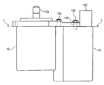
FIG. 3 is a bottom view as seen in a direction of an arrow mark B in FIGS. 1 and 2, showing relation of arrangement between the electric motor 12 and the control unit 15U. FIG. 4 is a side view of FIG. 3.
As shown in FIG. 3, apart of the flange part 13 is protruded in a circumferential direction (in this embodiment, the flange part 13 is protruded rightward at two positions substantially in C-shape) to form a flange protruded part 14. This flange protruded part 14 is formed with bolt holes 14 h at three positions, and fixing bolts 15 a, 15 b, 15 c are fitted into these bolt holes 14 h. A face of this flange protruded part 14 opposed to the main body of the electric motor 12 (a lower face of the flange protruded part 14 which is shown by an alternate long and short dash line in FIG. 4, hereinafter referred to as “a mounting face L”) is worked to be flat. As shown in FIG. 4, a mounting face of the control unit 15U (a lower face of the control unit 15U as shown in FIG. 2) is butted against this mounting face L, and the control unit 15U is detachably fixed to the mounting face L of the flange protruded part 14 by means of the fixing bolts 15 a, 15 b and 15 c.
A connector 15C and a terminal board 15B are detachably mounted on the lower face of the flange protruded part 14, that is, the mounting face of the control unit 15U which is mounted on the mounting face L, by means of small screws 15Cb and 15Bc respectively. This connector 15C takes various signals concerning running state of the vehicle such as the detected value of the steering torque which has been outputted from the aforesaid steering torque sensor into the controller 15. The terminal board 15B functions as an electrical connection part to the electric motor 12. Three output terminals 23A, 23B, and 23C (See FIG. 6) having tap holes (not shown) are formed in parallel on this terminal board 15B. As shown in FIG. 3, these output terminals 23A, 23B, 23C are fastened to end parts of bus bars 12A, 12B, and 12C extended from the electric motor 12 by means of small screws 12Ab, 12Bb, and 12Cb.
FIG. 5 is a sectional view taken along a line X-X in FIG. 3, as seen in a direction of arrow marks, showing the above described members, namely, the electric motor 12, the control unit 15U, the connector 15C, and the terminal board 15B in the mounted state.
As described above, the electric power steering apparatus is so constructed that the respective mounting faces of the electric motor 12, the control unit 15U, the connector 15C, and the terminal board 15B are on the same plane as the aforesaid mounting face L. Therefore, it is possible to mount these members in a single working step. As the results, mounting and assembling works of the members can be efficiently performed, and the manufacturing cost can be reduced.
Working steps for mounting and assembling these members are not particularly limited. For example, after the connector 15C and the terminal board 15B have been assembled to the control unit 15U as a first step, this control unit 15U may be assembled to the flange protruded part 14 of the electric motor 12 to set up the entire device, and thereafter, this flange protruded part 14 may be attached to the mounting member of the steering mechanism.
FIG. 6 schematically shows a structure of the controller 15 provided in the control unit 15U. As shown in FIG. 6, the controller 15 includes a board 15A. A control circuit 21 and a driving circuit 22 are mounted on this board 15A. Various data concerning the running state and so on of the vehicle as described above are sent to the control circuit 21 via the connector 15C. The control circuit 21 starts a determined program which has been stored in advance, to process the inputted data on the bases of algorism for assisting the steering force which is given by this program, and transmits results of the process to the driving circuit 22 at a determined timing. Then, the results of the process can be obtained, for example, as a duty ratio for switching power supply which is supplied to the driving circuit 22. In this manner, the driving circuit 22 outputs a driving electric power for driving the electric motor 12 on the bases of control by the control circuit 21. This output is transmitted to the output terminals 23A, 23B, 23C through wirings 33.
As described above, according to this electric power steering apparatus, the electric motor 12 and the control unit 15U are arranged in proximity to each other in a detachable manner, by means of the bus bars 12A, 23B, 12C having a short length. For this reason, the above described advantages by reducing the length of the electric wirings can be obtained. Specifically, the manufacturing cost can be reduced, by making the device compact and saving the cost for the material, and quality of the device can be enhanced, by decreasing electric power loss, noises, and heat generation. In addition, because the respective mounting faces of the electric motor 12, the control unit 15U, the connector 15C, and the terminal board 15B are so formed as to be on the same plane as the aforesaid mounting face L, it is possible to mount these members at the same time in a single working step. As the results, the manufacturing cost can be reduced due to the efficient mounting and assembling works of the members, as already described above.
Although the contents of the invention have been described referring to the embodiment, the invention is not necessarily limited to the above described embodiment.
For example, the electric power steering apparatus of the column assist type is exemplified in the above described embodiment, in which the electric motor 12 and the control unit 15U provided with the connector 15C and the terminal board 15B are directly mounted on the steering column 20 as the mounting member of the steering mechanism. However, the electric power steering apparatus according to the invention may be applied to the devices of other types, for example, the device of a pinion assist type or a rack assist type. Specifically, in case where the electric motor 12 and the control unit 15U are mounted on the steering mechanism, they can be mounted on a pinion shaft in case of the pinion assist type, and can be mounted on a rack shaft in case of the rack assist type.
As the mounting member of the electric motor 12, an appropriate member of the steering mechanism can be used, provided that the electric power steering apparatus according to the invention can be constructed. Further, for the purpose of favorably removing heat of the controller 15 by transferring the heat to a member having a large heat capacity, it would be preferable that the steering column is selected as the mounting member of the electric motor 12, as described above, and the flange protruded part 14 is directly mounted on this steering column, in case where the electric power steering apparatus is of the column assist type.
Although the invention has been fully described referring to the specified embodiment, it is apparent to those skilled in the art that various modifications and amendments may be added without departing from spirit and scope of the invention.
This invention is based on Japanese Patent Application No. 2005-298525 filed on Oct. 13, 2005, the contents of which are hereby incorporated by reference.
INDUSTRIAL APPLICABILITY
According to the invention, the electric power steering apparatus is so constructed that the mounting face of the electric motor with respect to the control unit, the mounting face of the terminal board provided on the control unit and used for electrical connection with the electric motor, and the mounting face of the connector mounted on the control unit are on the same plane. Therefore, it is possible to mount these members at the same time in a single working step. As the results, the mounting and assembling works of the members can be efficiently performed, and the manufacturing cost can be reduced.

Claims (6)

1. An electric power steering apparatus comprising:
a steering system into which steering torque is inputted;
an electric motor which imparts steering assist force to the steering system;
a controller which controls an energizing state of the electric motor according to the steering torque; and
a control unit provided with a terminal board and a connector which are electrically connected to the electric motor,
wherein a mounting face of the electric motor with respect to the control unit, a mounting face of the terminal board with respect to the control unit, and a mounting face of the connector with respect to the control unit are arranged on a same plane.
2. The electric power steering apparatus according to claim 1, wherein the mounting face of the electric motor with respect to the control unit is defined by a flange protruded part which is protruded from a flange part of the electric motor.
3. The electric power steering apparatus according to claim 1, wherein respective mounting members of the electric motor, the control unit, the terminal board and the connector are adapted to be attached or detached with respect to the same plane by fastening pieces.
4. The electric power steering apparatus according to claim 1, wherein a torque sensor which detects the steering torque is further provided, and
the connector is connected to the torque sensor,
whereby an electric signal corresponding to the steering torque is inputted into the controller via the connector.
5. The electric power steering apparatus according to claim 1, wherein a signal concerning running state of a vehicle is inputted into the controller via the connector.
6. The electric power steering apparatus according to claim 1, wherein the electric motor and the control unit are detachably connected to each other via a bus bar.
US12/090,106 2005-10-13 2006-09-14 Electric power steering apparatus Expired - Fee Related US7810607B2 (en)

Applications Claiming Priority (3)

Application Number Priority Date Filing Date Title
JP2005-298525 2005-10-13
JP2005298525A JP4701980B2 (en) 2005-10-13 2005-10-13 Electric power steering device
PCT/JP2006/318298 WO2007043283A1 (en) 2005-10-13 2006-09-14 Electric power steering device

Publications (2)

Publication Number Publication Date
US20090014231A1 US20090014231A1 (en) 2009-01-15
US7810607B2 true US7810607B2 (en) 2010-10-12

Family

ID=37942537

Family Applications (1)

Application Number Title Priority Date Filing Date
US12/090,106 Expired - Fee Related US7810607B2 (en) 2005-10-13 2006-09-14 Electric power steering apparatus

Country Status (5)

Country Link
US (1) US7810607B2 (en)
EP (1) EP1944218A1 (en)
JP (1) JP4701980B2 (en)
CN (1) CN101287638A (en)
WO (1) WO2007043283A1 (en)

Cited By (1)

* Cited by examiner, † Cited by third party
Publication number Priority date Publication date Assignee Title
US8910742B2 (en) 2011-08-26 2014-12-16 Nsk Ltd. Electric power-steering apparatus

Families Citing this family (10)

* Cited by examiner, † Cited by third party
Publication number Priority date Publication date Assignee Title
JP4661508B2 (en) * 2005-09-30 2011-03-30 日本精工株式会社 Electric power steering device
WO2008132931A1 (en) * 2007-04-19 2008-11-06 Nsk Ltd. Electric power steering device
JP2011157037A (en) * 2010-02-03 2011-08-18 Nsk Ltd Electric power steering device
JP5692593B2 (en) * 2011-05-11 2015-04-01 株式会社デンソー Drive device
JP5725343B2 (en) * 2011-05-11 2015-05-27 株式会社デンソー Drive device
JP5655694B2 (en) * 2011-05-11 2015-01-21 株式会社デンソー Drive device
JP5962822B2 (en) * 2011-08-26 2016-08-03 日本精工株式会社 Electric power steering device
JP5927836B2 (en) * 2011-10-19 2016-06-01 株式会社デンソー Drive device
JP5764459B2 (en) * 2011-10-19 2015-08-19 株式会社デンソー Drive device
KR20150041426A (en) * 2013-10-08 2015-04-16 현대모비스 주식회사 Powerpack device for mdps

Citations (11)

* Cited by examiner, † Cited by third party
Publication number Priority date Publication date Assignee Title
JPH11115775A (en) * 1997-10-20 1999-04-27 Mitsubishi Electric Corp Motor-driven power steering control device
US20030127921A1 (en) * 2002-01-08 2003-07-10 Mitsubishi Denki Kabushiki Kaisha Electric power steering apparatus
JP2003523708A (en) * 2000-02-19 2003-08-05 ローベルト ボツシユ ゲゼルシヤフト ミツト ベシユレンクテル ハフツング An electric motor for raising and lowering the window glass of automobiles
JP2003322082A (en) * 2002-04-26 2003-11-14 Denso Corp Inverter integrated type electric compressor for vehicle
JP2004066982A (en) * 2002-08-07 2004-03-04 Yazaki Corp Motor connection fixing structure for steering assembly
JP2005036773A (en) * 2003-07-18 2005-02-10 Denso Corp Inverter-integrated motor-driven compressor for vehicle
JP3638269B2 (en) * 2002-03-14 2005-04-13 三菱電機株式会社 Electric power steering device
US20050167183A1 (en) * 2004-02-02 2005-08-04 Mitsubishi Denki Kabushiki Kaisha Electric power steering apparatus
US20060108884A1 (en) * 2004-11-22 2006-05-25 Hitachi, Ltd. Motor control apparatus, power steering apparatus and brake control apparatus
US20070144822A1 (en) * 2005-11-21 2007-06-28 Mitsubishi Denki Kabushiki Kaisha Electric power steering apparatus
US7513331B2 (en) * 2005-09-30 2009-04-07 Nsk Ltd. Electric power steering device and attachment structure for motor and controller for the same

Family Cites Families (6)

* Cited by examiner, † Cited by third party
Publication number Priority date Publication date Assignee Title
JP3622362B2 (en) * 1996-09-19 2005-02-23 株式会社デンソー Electric power steering device
JPH11248564A (en) * 1998-02-26 1999-09-17 Nippon Seiko Kk Torque sensor
JP4618474B2 (en) * 2001-04-16 2011-01-26 株式会社ジェイテクト Electric power steering device
US6499558B2 (en) * 2001-05-17 2002-12-31 Delphi Technologies, Inc. Modular motor and controller assembly for rear-wheel steering system
JP4205550B2 (en) * 2002-11-19 2009-01-07 アスモ株式会社 Motor and motor manufacturing method
JP2005086855A (en) * 2003-09-05 2005-03-31 Showa Corp Motor control circuit assembling structure of power steering arrangement

Patent Citations (12)

* Cited by examiner, † Cited by third party
Publication number Priority date Publication date Assignee Title
JPH11115775A (en) * 1997-10-20 1999-04-27 Mitsubishi Electric Corp Motor-driven power steering control device
JP2003523708A (en) * 2000-02-19 2003-08-05 ローベルト ボツシユ ゲゼルシヤフト ミツト ベシユレンクテル ハフツング An electric motor for raising and lowering the window glass of automobiles
US20030127921A1 (en) * 2002-01-08 2003-07-10 Mitsubishi Denki Kabushiki Kaisha Electric power steering apparatus
JP2003204654A (en) * 2002-01-08 2003-07-18 Mitsubishi Electric Corp Motor-driven power steering device
JP3638269B2 (en) * 2002-03-14 2005-04-13 三菱電機株式会社 Electric power steering device
JP2003322082A (en) * 2002-04-26 2003-11-14 Denso Corp Inverter integrated type electric compressor for vehicle
JP2004066982A (en) * 2002-08-07 2004-03-04 Yazaki Corp Motor connection fixing structure for steering assembly
JP2005036773A (en) * 2003-07-18 2005-02-10 Denso Corp Inverter-integrated motor-driven compressor for vehicle
US20050167183A1 (en) * 2004-02-02 2005-08-04 Mitsubishi Denki Kabushiki Kaisha Electric power steering apparatus
US20060108884A1 (en) * 2004-11-22 2006-05-25 Hitachi, Ltd. Motor control apparatus, power steering apparatus and brake control apparatus
US7513331B2 (en) * 2005-09-30 2009-04-07 Nsk Ltd. Electric power steering device and attachment structure for motor and controller for the same
US20070144822A1 (en) * 2005-11-21 2007-06-28 Mitsubishi Denki Kabushiki Kaisha Electric power steering apparatus

Cited By (1)

* Cited by examiner, † Cited by third party
Publication number Priority date Publication date Assignee Title
US8910742B2 (en) 2011-08-26 2014-12-16 Nsk Ltd. Electric power-steering apparatus

Also Published As

Publication number Publication date
US20090014231A1 (en) 2009-01-15
JP4701980B2 (en) 2011-06-15
WO2007043283A1 (en) 2007-04-19
CN101287638A (en) 2008-10-15
JP2007106234A (en) 2007-04-26
EP1944218A1 (en) 2008-07-16

Similar Documents

Publication Publication Date Title
US7810607B2 (en) Electric power steering apparatus
JP4661508B2 (en) Electric power steering device
US10971976B2 (en) Electric drive device and electric power steering device
US9184640B2 (en) Motor controller and production method of the same
CN108093665B (en) Brushless motor, and electric power steering device and vehicle having the same
US20210221426A1 (en) Electric drive device of electric power steering apparatus
JP2009126350A (en) Electric power steering device
US20040080295A1 (en) Steering apparatus
JP2001158363A (en) Steering wire harness, steering module, and wiring system of steering wire harness
EP1731406A2 (en) Electric power steering unit and controller thereof
CN114132375B (en) Electric power steering assistance system and assistance device thereof
JP5999140B2 (en) Brushless motor, electric power steering apparatus equipped with the same, and vehicle
JP5212080B2 (en) Electric power steering device
JP5040522B2 (en) Electric power steering device
JP2009280018A (en) Electric power steering device
KR100795002B1 (en) Electronic control unit having gate drive module structure integrating pulse width modulation module
US8550205B2 (en) Electric power steering system
US8981605B2 (en) Motor drive apparatus with substrate fixed, member and rotation angle sensor
JP2009029287A (en) Electric power steering device
CN113544949A (en) Control device for a steering system of a motor vehicle, electromechanical power steering mechanism for a motor vehicle and steer-by-wire steering system
JP4835084B2 (en) Electric power steering device
US9878734B2 (en) Electric power steering apparatus
JP5176552B2 (en) Electric power steering device
KR102486396B1 (en) Power connector structure of motor and electronic control apparatus having the same
JP2017139858A (en) Connection structure for electric motor and substrate housed in controller therefor

Legal Events

Date Code Title Description
AS Assignment

Owner name: NSK LTD., JAPAN

Free format text: ASSIGNMENT OF ASSIGNORS INTEREST;ASSIGNORS:EBUCHI, TOMOAKI;YAMAMOTO, TAKESHI;MAEDA, MASAHIRO;REEL/FRAME:020796/0039

Effective date: 20080307

STCF Information on status: patent grant

Free format text: PATENTED CASE

FPAY Fee payment

Year of fee payment: 4

MAFP Maintenance fee payment

Free format text: PAYMENT OF MAINTENANCE FEE, 8TH YEAR, LARGE ENTITY (ORIGINAL EVENT CODE: M1552)

Year of fee payment: 8

FEPP Fee payment procedure

Free format text: MAINTENANCE FEE REMINDER MAILED (ORIGINAL EVENT CODE: REM.); ENTITY STATUS OF PATENT OWNER: LARGE ENTITY

LAPS Lapse for failure to pay maintenance fees

Free format text: PATENT EXPIRED FOR FAILURE TO PAY MAINTENANCE FEES (ORIGINAL EVENT CODE: EXP.); ENTITY STATUS OF PATENT OWNER: LARGE ENTITY

STCH Information on status: patent discontinuation

Free format text: PATENT EXPIRED DUE TO NONPAYMENT OF MAINTENANCE FEES UNDER 37 CFR 1.362

FP Lapsed due to failure to pay maintenance fee

Effective date: 20221012