US8863160B2 - Disc device having a carrier for retaining a plurality of discs in a stacked state - Google Patents
Disc device having a carrier for retaining a plurality of discs in a stacked state Download PDFInfo
- Publication number
- US8863160B2 US8863160B2 US13/903,306 US201313903306A US8863160B2 US 8863160 B2 US8863160 B2 US 8863160B2 US 201313903306 A US201313903306 A US 201313903306A US 8863160 B2 US8863160 B2 US 8863160B2
- Authority
- US
- United States
- Prior art keywords
- disc
- discs
- tray
- press
- topmost
- Prior art date
- Legal status (The legal status is an assumption and is not a legal conclusion. Google has not performed a legal analysis and makes no representation as to the accuracy of the status listed.)
- Active
Links
- 210000000078 claw Anatomy 0.000 claims abstract description 45
- 230000000717 retained effect Effects 0.000 claims abstract description 26
- 238000010586 diagram Methods 0.000 description 30
- 230000008878 coupling Effects 0.000 description 6
- 238000010168 coupling process Methods 0.000 description 6
- 238000005859 coupling reaction Methods 0.000 description 6
- 238000000034 method Methods 0.000 description 3
- 238000005192 partition Methods 0.000 description 3
- 238000012986 modification Methods 0.000 description 2
- 230000004048 modification Effects 0.000 description 2
- 239000002184 metal Substances 0.000 description 1
- 230000001105 regulatory effect Effects 0.000 description 1
- 239000011347 resin Substances 0.000 description 1
- 229920005989 resin Polymers 0.000 description 1
- 230000000630 rising effect Effects 0.000 description 1
Images


Classifications
-
- G—PHYSICS
- G11—INFORMATION STORAGE
- G11B—INFORMATION STORAGE BASED ON RELATIVE MOVEMENT BETWEEN RECORD CARRIER AND TRANSDUCER
- G11B17/00—Guiding record carriers not specifically of filamentary or web form, or of supports therefor
- G11B17/02—Details
- G11B17/04—Feeding or guiding single record carrier to or from transducer unit
- G11B17/05—Feeding or guiding single record carrier to or from transducer unit specially adapted for discs not contained within cartridges
- G11B17/053—Indirect insertion, i.e. with external loading means
-
- G—PHYSICS
- G11—INFORMATION STORAGE
- G11B—INFORMATION STORAGE BASED ON RELATIVE MOVEMENT BETWEEN RECORD CARRIER AND TRANSDUCER
- G11B17/00—Guiding record carriers not specifically of filamentary or web form, or of supports therefor
- G11B17/22—Guiding record carriers not specifically of filamentary or web form, or of supports therefor from random access magazine of disc records
- G11B17/225—Guiding record carriers not specifically of filamentary or web form, or of supports therefor from random access magazine of disc records wherein the disks are transferred from a fixed magazine to a fixed playing unit using a moving carriage
-
- G—PHYSICS
- G11—INFORMATION STORAGE
- G11B—INFORMATION STORAGE BASED ON RELATIVE MOVEMENT BETWEEN RECORD CARRIER AND TRANSDUCER
- G11B23/00—Record carriers not specific to the method of recording or reproducing; Accessories, e.g. containers, specially adapted for co-operation with the recording or reproducing apparatus ; Intermediate mediums; Apparatus or processes specially adapted for their manufacture
- G11B23/02—Containers; Storing means both adapted to cooperate with the recording or reproducing means
- G11B23/03—Containers for flat record carriers
- G11B23/032—Containers for flat record carriers for rigid discs
- G11B23/0323—Containers for flat record carriers for rigid discs for disc-packs
Definitions
- the technical field relates to a disc device that supplies a disc (a disc-like information recording medium such as a CD or a DVD) to each of a plurality of disc drives.
- a disc a disc-like information recording medium such as a CD or a DVD
- a device disclosed in Patent Document 1 (No. 2011-204311 A) is known, for example.
- the disc device disclosed in Patent Document 1 includes a magazine that stores a plurality of trays that stores one disc, and a plurality of disc drives.
- the disc device disclosed in Patent Document 1 is structured such that: an arbitrary tray is drawn out from the magazine; one disc stored in the drawn out tray is suctioned and held by a suction pad; and the disc is placed on the tray of an arbitrary disc drive.
- the number of discs that can be stored in the magazine is small because the disc device is structured to store one disc per tray.
- it may be effective to directly stack a plurality of discs without use of the trays, to thereby reduce the number of trays.
- Patent Document 2 (No. 2000-117553 A) discloses the technique for solving such a problem.
- Patent Document 2 discloses the following technique: separating adjacent two discs from each other by inserting claw portions between the two discs; and allowing the separated discs to be suctioned and held by suction pads.
- Patent Document 1 JP 2011-204311 A
- Patent Document 2 JP 2000-117553 A
- Patent Document 2 cannot prevent the increase in time of supplying the discs to the plurality of disc drives.
- the applicant of the present disclosure has developed a disc device including a carrier that retains a stacked plurality of discs in such a stacked state, that separates one disc from the retained plurality of discs above a tray ejected from an arbitrary disc drive, and that places the separated disc onto the tray.
- the disc device is structured to: insert a spindle unit into the center holes of the stacked plurality of discs; causing a plurality of claw portions to project from the spindle unit; holding the bottommost disc by the plurality of claw portions; and retaining the plurality of discs in such a stacked state.
- the disc device is structured to hold only the inner circumferential portion of the bottommost disc by the plurality of claw portions, to retain the plurality of discs in the stacked state. Accordingly, the outer circumferential side of the discs tends to wobble, and the discs may fail to be accurately placed on the tray.
- one non-limiting and exemplary embodiment provides a disc device that can stably retain a stacked plurality of discs in such a stacked state, and that can place each disc on the tray of each of a plurality of disc drives more accurately.
- a disc device supplying a disc to each of a plurality of disc drives, the disc device comprising
- a carrier which retains a plurality of discs being stacked in such a stacked state, which separates one disc from the retained plurality of discs above a tray ejected from an arbitrary one of the disc drives, and which places the separated disc on the tray,
- the carrier includes:
- a disc press which presses a topmost disc out of the plurality of discs so as to be in parallel to a disc placing face of the tray.
- provision of the disc press makes it possible to stably retain the stacked plurality of discs in such a stacked state, and to more accurately place a disc to corresponding one of the trays of the plurality of disc drives.
- FIG. 1 is a perspective view showing the schematic structure of a disc device according to an embodiment of the present disclosure.
- FIG. 2A is a perspective view of a magazine included in the disc device shown in FIG. 1 .
- FIG. 2B is an exploded perspective view of the magazine shown in FIG. 2A .
- FIG. 3 is a perspective view of a picker included in the disc device shown in FIG. 1 .
- FIG. 4 is a plan view showing the structure of a drive system of an up-and-down table included in the picker shown in FIG. 3 .
- FIG. 5 is a perspective view of the picker shown in FIG. 3 as seen diagonally from below.
- FIG. 6 is a plan view showing the state where the picker shown in FIG. 3 shifts to the position at the front of the magazine selected from a plurality of magazines.
- FIG. 7 is a plan view showing the manner of the picker shown in FIG. 3 drawing out a magazine tray from the magazine.
- FIG. 8 is a plan view showing the manner of the picker shown in FIG. 3 drawing out the magazine tray from the magazine.
- FIG. 9 is a plan view showing the manner of the picker shown in FIG. 3 drawing out the magazine tray from the magazine.
- FIG. 10 is a plan view showing the manner of the picker shown in FIG. 3 drawing out the magazine tray from the magazine.
- FIG. 11 is a plan view showing the manner of the picker shown in FIG. 3 drawing out the magazine tray from the magazine.
- FIG. 12 is a plan view showing the state where the picker shown in FIG. 3 has drawn out the magazine tray from the magazine.
- FIG. 13 is a plan view showing the state where the picker shown in FIG. 3 has conveyed the magazine tray to a position near the plurality of disc drives.
- FIG. 14 is a perspective view showing the state where the picker shown in FIG. 3 has conveyed the magazine tray to a position near the plurality of disc drives.
- FIG. 15 is a perspective view showing the state where the picker shown in FIG. 3 has shifted the magazine tray to a position above a lifter included in the disc device shown in FIG. 1 .
- FIG. 16 is an exploded perspective view showing the state where a magazine tray guide of the lifter included in the disc device shown in FIG. 1 is removed.
- FIG. 17 is an assembly perspective view showing the state where the magazine tray guide of the lifter included in the disc device shown in FIG. 1 is removed.
- FIG. 18 is a perspective view of a carrier included in the disc device shown in FIG. 1 .
- FIG. 19 is a partial enlarged side view of the carrier shown in FIG. 18 .
- FIG. 20 is a perspective view showing the state where a disc chuck unit included in the carrier shown in FIG. 18 is lowered to a position above and near the magazine tray.
- FIG. 21 is a perspective view showing the state where all the discs are held by the disc chuck unit.
- FIG. 22 is a perspective view showing the state, which follows the state shown in FIG. 21 , where the picker has shifted to the device-front side, and the magazine tray has receded from the position near the disc drive.
- FIG. 23 is a perspective view showing the state, which follows the state shown in FIG. 22 , where a tray of the bottommost-stage disc drive is ejected.
- FIG. 24 is a perspective view showing the state, which follows the state shown in FIG. 23 , where a shift base is lowered such that the plurality of discs retained by the disc chuck unit position above the tray.
- FIG. 25 is a perspective view showing the state where the bottommost disc is placed on the tray.
- FIG. 26 is a perspective view showing the state, which follows the state shown in FIG. 25 , where the tray has been carried into the disc drive.
- FIG. 27 is a perspective view where the carrier places a disc on the tray of the topmost-stage disc drive.
- FIG. 28 is a perspective view showing the state where a plurality of discs collected by the carrier are stored in the magazine tray.
- FIG. 29 is an exploded perspective view of the disc chuck unit included in the carrier shown in FIG. 18 as seen diagonally from above.
- FIG. 30 is an exploded perspective view of the disc chuck unit included in the carrier shown in FIG. 18 as seen diagonally from below.
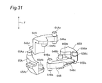
- FIG. 31 is an enlarged perspective view of two separator hooks and two bottom hooks included in the disc chuck unit shown in FIG. 29 .
- FIG. 32 is a cross sectional view showing the discs each provided with a recess portion at their inner circumferential portion.
- FIG. 33 is a perspective view showing the state where a spindle head included in the disc chuck unit shown in FIG. 29 is fixed to the bottom end portion of a spindle shaft by a screw.
- FIG. 34 is a perspective view of the spindle head included in the disc chuck unit shown in FIG. 29 .
- FIG. 35 is an exploded perspective view of a camshaft unit included in the disc chuck unit shown in FIG. 29 .
- FIG. 36 is a perspective view of two cam plates included in the camshaft unit shown in FIG. 35 as seen diagonally from below.
- FIG. 37A is a diagram showing the manner of a drive pin of one separator hook sliding along a cam groove formed at the top face of one cam plate.
- FIG. 37B is a diagram showing the manner of the drive pin of the one separator hook sliding along the cam groove formed at the top face of the one cam plate.
- FIG. 37C is a diagram showing the manner of the drive pin of the one separator hook sliding along the cam groove formed at the top face of the one cam plate.
- FIG. 37D is a diagram showing the manner of the drive pin of the one separator hook sliding along the cam groove formed at the top face of the one cam plate.
- FIG. 38A is a diagram showing the manner of a drive pin of other separator hook sliding along a cam groove formed at the bottom face of the one cam plate.
- FIG. 38B is a diagram showing the manner of the drive pin of the other separator hook sliding along the cam groove formed at the bottom face of the one cam plate.
- FIG. 38C is a diagram showing the manner of the drive pin of the other separator hook sliding along the cam groove formed at the bottom face of the one cam plate.
- FIG. 38D is a diagram showing the manner of the drive pin of the other separator hook sliding along the cam groove formed at the bottom face of the one cam plate.
- FIG. 39A is a diagram showing the manner of a drive pin of one bottom hook sliding along a cam groove formed at the top face of other cam plate.
- FIG. 39B is a diagram showing the manner of the drive pin of the one bottom hook sliding along the cam groove formed at the top face of the other cam plate.
- FIG. 39C is a diagram showing the manner of the drive pin of the one bottom hook sliding along the cam groove formed at the top face of the other cam plate.
- FIG. 39D is a diagram showing the manner of the drive pin of the one bottom hook sliding along the cam groove formed at the top face of the other cam plate.
- FIG. 40A is a diagram showing the manner of a drive pin of other bottom hook sliding along a cam groove formed at the bottom face of the other cam plate.
- FIG. 40B is a diagram showing the manner of the drive pin of the other bottom hook sliding along the cam groove formed at the bottom face of the other cam plate.
- FIG. 40C is a diagram showing the manner of the drive pin of the other bottom hook sliding along the cam groove formed, at the bottom face of the other cam plate.
- FIG. 40D is a diagram showing the manner of the drive pin of the other bottom hook sliding along the cam groove formed at the bottom face of the other cam plate.
- FIG. 41A is a diagram showing the manner of the hooks shown in FIGS. 37A to 40D sliding along corresponding cam grooves, focusing on the positional relationship between a camshaft and the hooks.
- FIG. 41B is a diagram showing the manner of the hooks shown in FIGS. 37A to 40D sliding along corresponding cam grooves, focusing on the positional relationship between the camshaft and the hooks.
- FIG. 41C is a diagram showing the manner of the hooks shown in FIGS. 37A to 40D sliding along corresponding cam grooves, focusing on the positional relationship between the camshaft and the hooks.
- FIG. 41D is a diagram showing the manner of the hooks shown in FIGS. 37A to 40D sliding along corresponding cam grooves, focusing on the positional relationship between the camshaft and the hooks.
- FIG. 42 is a diagram schematically showing the manner of the carrier shown in FIG. 18 separating one disc from a plurality of discs.
- FIG. 43 is a diagram schematically showing the manner of the carrier shown in FIG. 18 separating one disc from a plurality of discs.
- FIG. 44 is a diagram schematically showing the manner of the carrier shown in FIG. 18 separating one disc from a plurality of discs.
- FIG. 45 is a diagram schematically showing the manner of the carrier shown in FIG. 18 separating one disc from a plurality of discs.
- FIG. 46 is a diagram schematically showing the manner of the carrier shown in FIG. 18 separating one disc from a plurality of discs.
- FIG. 47 is a diagram schematically showing the manner of the carrier shown in FIG. 18 separating one disc from a plurality of discs.
- FIG. 48 is a diagram schematically showing the manner of the carrier shown in FIG. 18 separating one disc from a plurality of discs.
- FIG. 49 is a diagram schematically showing the manner of the carrier shown in FIG. 18 separating one disc from a plurality of discs.
- FIG. 50 is a diagram schematically showing the manner of the carrier shown in FIG. 18 separating one disc from a plurality of discs.
- FIG. 51 is a partially transparent perspective view of the positional relationship among the shift base, a disc press, and an encoder included in the carrier shown in FIG. 18 , in the state where the disc press is pressing no discs.
- FIG. 52 is a partially transparent perspective view of the positional relationship among the shift base, the disc press, and the switch included in the carrier shown in FIG. 18 , in the state where the disc press is pressing a plurality of discs.
- FIG. 53 is a side view showing the positional relationship among the shift base, the disc press, and the switch included in the carrier shown in FIG. 18 , in the state where the disc press is pressing a plurality of discs.
- FIG. 54 is a partially transparent perspective view of the positional relationship among the shift base, the disc press, and the switch included in the carrier shown in FIG. 18 , in the state where the disc press is in contact with the switch.
- FIG. 55 is a side view showing the positional relationship among the shift base, the disc press, and the switch included in the carrier shown in FIG. 18 , in the state where the disc press is in contact with the switch.
- FIG. 56A is a partially transparent plan view showing the positional relationship among the disc chuck unit, the shift base, and the disc press included in the carrier shown in FIG. 18 , in the state where the disc press is pressing one disc.
- FIG. 56B is a cross sectional view taken along line A-A in FIG. 56 A.
- a disc device supplying a disc to each of a plurality of disc drives, the disc device comprising
- a carrier which retains a plurality of discs being stacked in such a stacked state, which separates one disc from the retained plurality of discs above a tray ejected from an arbitrary one of the disc drives, and which places the separated disc on the tray,
- the carrier includes:
- a disc press which presses a topmost disc out of the plurality of discs so as to be in parallel to a disc placing face of the tray.
- the disc press is provided so as to be rotatable about one end portion of the disc press, and so that other end portion of the disc press is brought into contact with the topmost disc.
- the other end portion of the disc press is provided so as to be brought into contact with a substantial diameter portion of the topmost disc.
- the other end portion of the disc press is provided so as to, in planar view, pass a line segment connecting between two claw portions out of the plurality of claw portions, and to extend in a direction crossing the line segment.
- a length of a contact portion between the topmost disc and the other end portion of the disc press is substantially identical to a length of a diameter of the disc subtracted by a diameter of a center hole of the disc.
- the carrier further includes a disc height position detecting unit detecting a height position of the topmost disc.
- the carrier includes a disc height position detecting unit, the disc height position detecting unit sensing a rotation amount of the disc press to sense a height position of the topmost disc.
- the disc device according to any one of the first to seventh aspects, further comprising
- a disc presence-absence detecting unit being out of contact with the disc press when the carrier retains the disc, and being in contact with the disc press when the carrier does not retain the disc, to sense presence and absence of the disc retained by the carrier.
- FIG. 1 is a perspective view showing the schematic structure of a disc device according to an embodiment of the present disclosure. It is to be noted that, in the present embodiment, the left side in FIG. 1 is referred to as the “device-front side”, and the right side in FIG. 1 is referred to as the “device-rear side”.
- the disc device includes two magazine stockers 1 , 1 .
- the two magazine stockers 1 , 1 are provided on a bottom chassis 11 so as to oppose to each other in a device width direction Y. It is to be noted that, in FIG. 1 , one of the magazine stockers 1 (on the near side) is not shown. Further, the top panel and the partition plate of the magazine stocker 1 are not shown in FIG. 1 .
- Each magazine stocker 1 stores a plurality of magazines 2 .
- Each magazine 2 includes magazine trays 21 storing a plurality of (e.g., 12 pieces of) discs. Between the two magazine stockers 1 , 1 , a picker 3 that draws out the magazine tray 21 from one magazine 2 selected from a plurality of magazines 2 and that holds the magazine tray 21 is provided.
- the picker 3 is structured to convey the held magazine tray 21 to a position near a plurality of disc drives 4 arranged at the device-rear side.
- the picker 3 is integrally provided with a lifter 5 that pushes out a plurality of discs from the magazine tray 21 .
- the disc drives 4 are each an apparatus that performs recording or reproducing of information on or from a disc. Further, the disc drives 4 are each a tray-scheme disc drive that load discs using trays.
- the plurality of disc drives 4 are stacked in a device height direction Z, and arranged so as to be adjacent to the magazine stockers 1 , 1 on the device-rear side. Between the plurality of disc drives 4 arranged as being stacked so as to be adjacent to one magazine stocker 1 and the plurality of disc drives 4 arranged as being stacked so as to be adjacent to the other magazine stocker 1 , a carrier 6 is provided.
- the carrier 6 is structured to: retain a plurality of discs pushed out by the lifter 5 in such a stacked state; separate one disc from the retained plurality of discs above a tray 4 a (see FIG. 23 ) ejected from an arbitrary disc drive 4 ; and place the separated disc on the tray 4 a.
- an electric circuit and a power supply 7 are provided.
- the electric circuit and the power supply 7 are provided with a control unit that controls operations (motor and the like) of devices such as the picker 3 , the disc drives 4 , the carrier 6 , and the like.
- the control unit is connected to, for example, a host computer that manages data.
- the host computer sends commands to the control unit to perform operations such as data reading from or writing on the specified magazine 2 , based on instructions from the operator.
- the control unit controls the operation of the devices such as the picker 3 , the disc drive 4 , the carrier 6 , and the like according to the commands.
- the magazine stockers 1 are provided along guide rails 12 that slidably guide the picker 3 .
- the guide rails 12 are provided so as to extend in a device depth direction X (in the longitudinal direction of the magazine stockers 1 ).
- a grip 13 is provided at the side face on the device-front side of each magazine stocker 1 .
- the magazine stocker 1 can be shifted toward the device-front side by the grip 13 being pulled.
- Each magazine stocker 1 is provided with a partition plate (not shown) formed to be grid-like as seen from the device width direction Y. In each of the space surrounded by the partition plate, the magazine 2 is stored.
- the magazine 2 includes the magazine tray 21 , and a case 22 that has a substantially rectangular parallelepiped shape and that stores the magazine tray 21 .
- a case 22 that has a substantially rectangular parallelepiped shape and that stores the magazine tray 21 .
- an opening 22 a into which the magazine tray 21 can be inserted and taken out is provided.
- the magazine tray 21 is formed to have an outer shape being substantially rectangular in planar view.
- the magazine tray 21 stores a plurality of discs 100 as being stacked in close contact with one another.
- cut portions 21 a , 21 a are formed.
- a side face 21 b that positions on the back side of the magazine case 22 in the state where the magazine tray 21 is stored in the magazine case 22 is formed to be arc-like as a whole including the cut portions 21 a , 21 a.
- cutout portions 21 c , 21 c are formed.
- engaging recess portions 21 d , 21 d with which a pair of hooks 35 , 35 , whose description will follow, engage are formed.
- the magazine tray 21 is provided with a core rod, which is inserted into a center hole 100 a provided at each of the plurality of discs 100 to restrict shifting of the discs 100 in the plane direction.
- This core rod 38 prevents the discs 100 from being damaged by such shifting of the discs 100 in the plane direction.
- the core rod 23 is provided with an engaging portion 23 a for engaging with a spindle head 67 b of a disc chuck unit 62 , whose description will follow.
- three holes 21 e are provided at an interval of 120 degrees. Further, the three holes 21 e are provided at the position opposing to the non-recording-and-reproducing region of the inner circumferential portion of each disc 100 when the disc 100 is inserted into the core rod 23 .
- the picker 3 includes a run base 31 .
- a movable platform 31 a slidably shifting along the guide rail 12 is attached on one magazine stocker 1 side of the run base 31 .
- a roller 31 b is attached on other magazine stocker 1 side of the run base 31 .
- the run base 31 is provided with a picker motor 31 c that produces drive force for causing the picker 3 to shift in the device depth direction X.
- a reduction gear 31 d meshes with a motor gear 31 i , into which the drive shaft of the picker motor 31 c is press fitted.
- the reduction gear 31 d meshes with a pinion gear 31 e .
- the pinion gear 31 e meshes with a rack 14 provided adjacent to the guide rail 12 to extend in the device depth direction X.
- the drive force of the picker motor 31 c is transferred to the pinion gear 31 e via the motor gear 31 i and the reduction gear 31 d , to rotate the pinion gear 31 e .
- the rack 14 is fixed to the bottom chassis 11 .
- the run base 31 is not fixed to the bottom chassis 11 . Accordingly, when the pinion gear 31 e rotates, the pinion gear 31 e shifts along the rack 14 , whereby the picker 3 shifts in the device depth direction X.
- the picker motor 31 c for example, a stepping motor is employed. Applying a prescribed pulse to the picker motor 31 c , the picker 3 can be shifted to be located at the front of a prescribed magazine 2 .
- a picker base 31 h made of resin is attached to the run base 31 made of a sheet metal.
- the picker base 31 h is provided with a rotary table 32 so as to be rotatable substantially about a rotation axis 32 a extending in the device height direction Z.
- the picker base 31 h is provided with a rotary table motor 31 f that produces the drive force for causing the rotary table 32 to rotate.
- a reduction gear 31 g meshes with the motor gear 31 j , into which the drive shaft of the rotary table motor 31 f is press fitted.
- the reduction gear 31 g meshes with a rotary table gear 32 b provided at the outer circumferential portion of the rotary table 32 .
- the rotary table 32 is provided with a pair of up-and-down rails 33 , 33 extending along the device height direction Z and opposing to each other. Between the pair of up-and-down rails 33 , 33 , an up-and-down table 34 is provided. Further, the rotary table 32 is provided with an up-and-down table motor 32 c that produces the drive force for causing the up-and-down table 34 to rise and lower.
- a relay gear 32 d meshes with a motor gear 32 k , into which the drive shaft of the up-and-down table motor 32 c is press fitted.
- the relay gear 32 d meshes with a coupling shaft gear 32 e .
- a coupling shaft 32 f penetrates through the center portion of the coupling shaft gear 32 e .
- Worms 32 g , 32 g are fixed to the opposite ends of the coupling shaft 32 f .
- the worms 32 g mesh with relay gears 32 h .
- the relay gears 32 h mesh with lead screw gears 32 i .
- the lead screw gears 32 i are fixed to lead screws 32 j .
- the lead screws 32 j are provided so as to extend in the device height direction Z along the up-and-down rails 33 . As shown in FIG. 3 , nuts 34 a provided to the up-and-down table 34 are screwed with the lead screws 32 j.
- the drive force of the up-and-down table motor 32 c is transferred to the lead screws 32 j via the motor gear 32 k , the relay gear 32 d , the coupling shaft gear 32 e , the coupling shaft 32 f , the worms 32 g , the relay gears 32 h , and the lead screw gears 32 i , whereby the lead screws 32 j rotate.
- the up-and-down table 34 rises and lowers in the device height direction Z along the pair of up-and-down rails 33 and 33 .
- the up-and-down table 34 is provided with a pair of hooks 35 , 35 that can engage with engaging recess portions 21 d of the magazine tray 21 , and a chuck 36 functioning to open and close the pair of hooks 35 , 35 and to cause the pair of hooks 35 , 35 to shift forward and backward.
- the up-and-down table 34 is provided with a chuck motor 34 b .
- a reduction gear 34 c meshes with a motor gear 34 f , into which the drive shaft of the chuck motor 34 b is press fitted.
- the reduction gear 34 c meshes with a lead screw gear 34 d .
- the lead screw gear 34 d is fixed to a lead screw 34 e .
- the lead screw 34 e is provided to extend in the direction perpendicular to the line connecting between the pair of up-and-down rails 33 and 33 .
- a nut 36 a fixed to the chuck 36 is screwed with the lead screw 34 e.
- the drive force of the chuck motor 34 b is transferred to the nut 36 a via the motor gear 34 f , the reduction gear 34 c , the lead screw gear 34 d , and the lead screw 34 e , whereby the chuck 36 shifts along the lead screw 34 e.
- the chuck 36 is structured to be capable of adjusting the interval of the pair of hooks 35 , 35 .
- the pair of hooks 35 , 35 can engage with the engaging recess portions 21 d , 21 d of the magazine tray 21 .
- the chuck 36 increasing the interval of the pair of hooks 35 , 35 , the engaged state between the pair of hooks 35 , 35 and the engaging recess portions 21 d , 21 d of the magazine tray 21 can be released.
- the paired up-and-down rails 33 are attached to opposite side faces of a U-shaped angle plate 37 , respectively.
- the top end portions of the paired lead screws 32 j are rotatably attached to the top face of the angle plate 37 .
- the picker motor 31 c , the rotary table motor 31 f , the up-and-down table motor 32 c , and the chuck motor 34 b are connected to the control unit of the electric circuit and the power supply 7 via an FFC (flexible flat cable) 114 (see FIG. 1 ), and drive under control of the control unit.
- FFC flexible flat cable
- FIGS. 6 to 12 each show the manner of the picker 3 drawing out the magazine tray 21 from the case 22 .
- the picker 3 shifts to the location at the front of one magazine 2 selected from a plurality of magazines 2 .
- the rotary table 32 is rotated so that the chuck 36 is oriented to the front side of the magazine 2 .
- the chuck 36 advances toward the magazine tray 21 , whereby, as shown in FIG. 9 , the pair of hooks 35 , 35 is engaged with the engaging recess portions 21 d , 21 d of the magazine tray 21 .
- the magazine tray 21 is drawn out from the case 22 .
- the magazine tray 21 drawn out from the case 22 is conveyed to the location near the plurality of disc drives 4 as shown in FIGS. 13 and 14 , by the run base 31 of the picker 3 running to the device-rear side. Thereafter, as shown in FIG. 15 , the chuck 36 of the picker 3 advances, and the magazine tray 21 is placed at a prescribed position on the magazine tray guide 51 at the top of the lifter 5 .
- the disc drives 4 on the near side are not shown in FIGS. 14 and 15 .
- the disc drives 4 on the near side are not shown also in FIGS. 21 to 28 , which will be referred to later.
- FIG. 16 is an exploded perspective view showing the state where the magazine tray guide 51 of the lifter 5 is taken out
- FIG. 17 is an assembly perspective view thereof.
- the lifter 5 includes an up-and-down plate 52 , a rotary cam 53 , a drive gear 54 , a relay gear 55 , and a lifter motor 56 .
- the up-and-down plate 52 includes up-and-down pins 52 a each being an exemplary rod-like member, and cam pins 52 b .
- the three up-and-down pins 52 a are provided at an interval of 120 degrees, and so are the three cam pins 52 b.
- the three up-and-down pins 52 a are provided at positions where they agree with the three holes 21 e provided at the magazine tray 21 as shown in FIG. 2B , when the magazine tray 21 is placed at the prescribed position on the magazine tray guide 51 as shown in FIG. 15 . Further, as shown in FIG. 14 , the magazine tray guide 51 is provided with three holes 51 a at the positions corresponding to the three up-and-down pins 52 a .
- the three cam pins 52 b are engaged with three slits 5 a provided at the body of the lifter 5 .
- the slits 5 a are provided so as to extend in the device height direction Z.
- cam grooves 53 a are provided at the inner circumferential face of the rotary cam 53 .
- Each cam groove 53 a has an inclined face along which the tip portion of corresponding one of the three cam pins 52 b slides.
- a cam gear 53 b is provided at the outer circumferential face of the rotary cam 53 .
- the cam gear 53 b meshes with the drive gear 54 .
- the drive gear 54 meshes with the relay gear 55 .
- the relay gear 55 meshes with the motor gear (not shown), into which the drive shaft of the lifter motor 56 is press fitted.
- the drive force of the lifter motor 56 is transferred to the drive gear 54 via the motor gear (not shown) and the relay gear 55 , whereby the drive gear 54 rotates.
- the rotary cam 53 meshing with the drive gear 54 by the cam gear 53 b rotates.
- tip portions of the three cam pins 52 b whose rotation is regulated by the three slits 5 a , slide along the inclined face of the three cam grooves 53 a , and the up-and-down plate 52 rises and lowers in the device height direction Z.
- the lifter motor 56 is connected to the control unit of the electric circuit and the power supply 7 via the FFC 14 (see FIG. 1 ), and drives under control of the control unit.
- the up-and-down plate 52 rises, the three up-and-down pins 52 a enter inside the magazine tray 21 through the three holes 51 a of the magazine tray guide 51 and the three holes 21 e of the magazine tray 21 .
- the rising of the three up-and-down pins 52 a a plurality of discs 100 are pushed out from the magazine tray 21 .
- the plurality of discs 100 pushed out by the three up-and-down pins 52 a are retained by the carrier 6 .
- the carrier 6 is provided at a housing 8 storing a plurality of (e.g., 12 pieces of) disc drives 4 .
- the carrier 6 includes a shift base 61 shifting in the device height direction Z and a disc chuck unit 62 provided at the shift base 61 .
- the shift base 61 is connected to a ball screw 91 via a bush 61 a and connected to a guide shaft 92 via a guide shaft bearing 61 b .
- the ball screw 91 and the guide shaft 92 are provided so as to extend in the device height direction Z.
- a pulley 91 a is attached to the top end portion of the ball screw 91 .
- the housing 8 is provided with a carrier motor 93 that produces the drive force for rotating the ball screw 91 about its axis.
- a pulley 93 a is attached to the drive shaft of the carrier motor 93 .
- a belt 94 is wrapped around the pulley 91 a and the pulley 93 a.
- the carrier motor 93 When the carrier motor 93 is driven, the drive force of the carrier motor 93 is transferred to the ball screw 91 via the pulley 93 a , the belt 94 , and the pulley 91 a , and the ball screw 91 rotates about its axis.
- the shift base 61 By the rotation of the ball screw 91 , the shift base 61 is guided by the ball screw 91 and the guide shaft 92 and shifts in the device height direction Z.
- the carrier motor 93 is connected to the control unit of the electric circuit and the power supply 7 , and drives under control of the control unit.
- the disc chuck unit 62 is structured to retain a plurality of discs 100 pushed out by the lifter 5 , and to separate the retained plurality of discs 100 one by one.
- the detail of the structure of the shift base 61 and the disc chuck unit 62 will be detailed later.
- the up-and-down pins 52 a enter inside the magazine tray 21 through the holes 51 a and 21 e , to push out a plurality of discs 100 from the magazine tray 21 .
- the disc chuck unit 62 retains the plurality of discs 100 .
- FIG. 24 is a perspective view showing the state where the bottommost disc 100 is placed on the tray 4 a.
- the shift base 61 is raised such that the disc chuck unit 62 and the tray 4 a are not brought into contact with each other. Thereafter, as shown in FIG. 26 , the tray 4 a is carried into the disc drive 4 . Thereafter, or simultaneously therewith, the tray 4 a of the disc drive 4 opposing to the handled disc drive is ejected (not shown). Thereafter, in the manner similarly to that described above, a disc 100 is placed on the tray 4 a , and the tray 4 a is carried into the disc drive 4 . Thus, the loading operation as to the disc drives 4 of the bottommost stage (first stage) is completed. This loading operation is repeated as to the second and following stages.
- FIG. 27 shows the manner in which a disc 100 is placed on the tray 4 a of the disc drive 4 of the topmost stage (e.g., sixth stage).
- the topmost stage e.g., sixth stage.
- the collection of the discs 100 in the disc drives 4 should be performed in the order reverse to the foregoing manner, for example. Specifically, it is performed as follows.
- the tray 4 a of the topmost-stage disc drive 4 is ejected.
- the disc chuck unit 62 is inserted into the center hole 100 a of the disc 100 on the tray 4 a , and the disc chuck unit 62 retains the disc 100 .
- the tray 4 a from which the disc 100 is collected by the disc chuck unit 62 is carried into the disc drive 4 .
- the tray 4 a of the disc drive 4 opposing to the handled disc drive is ejected (not shown).
- the disc 100 of the tray 4 a is collected by the disc chuck unit 62 , and the tray 4 a is carried into the disc drive 4 .
- the disc collection operation as to the disc drives 4 of the topmost stage (first stage) is completed. This disc collection operation is repeated until the discs 100 in the bottommost-stage disc drives 4 are collected.
- the shift base 61 is raised. Thereafter, the picker 3 shifts to the device-rear side, and the magazine tray 21 is set below the disc chuck unit 62 .
- the shift base 61 is lowered, and the tip portion of the disc chuck unit 62 engages with the engaging portion 23 a (see FIG. 2B ) of the core rod 23 , whereby the disc chuck unit 62 and the core rod 23 become coaxial to each other.
- the magazine tray 21 having stored all the discs 100 are returned into the magazine stocker 1 by the picker 3 .
- This conveyance of the magazine tray 21 into the magazine stocker 1 is achieved by, for example, performing the operations that are reverse to the operations having been described with reference to FIGS. 6 to 15 .
- the disc chuck unit 62 includes separator hooks 64 A, 64 B, bottom hooks 65 A, 65 B, a spindle unit 66 , and a camshaft unit 67 .
- FIG. 31 is an enlarged perspective view of the separator hooks 64 A, 64 B and the bottom hooks 65 A, 65 B.
- the hooks 64 A to 65 B are formed to be substantially lever-shaped, and include rotary shafts 64 Aa to 65 Ba and drive pins 64 Ab to 65 Bb extending in the device height direction Z, and claw portions 64 Ac to 65 Bc projecting in the direction crossing the device height direction Z.
- each disc 100 is provided with a recess portion 100 b .
- the recess portion 100 b is formed to have a shape obtained by cutting the top corner portion of the inner circumferential portion of the disc 100 so as to have a level face 100 ba and an inclined face 100 bb .
- the bottom faces of the claw portions 64 Ac, 64 Bc of the separator hooks 64 A, 64 B are each formed to have an inclined face, such that the thickness becomes greater downward from the outer circumferential side to the inner circumferential side.
- the top faces of the claw portions 64 Ac to 65 Bc are formed to be perpendicular to the device height direction Z.
- the spindle unit 66 includes a spindle shaft 66 a of a substantially cylindrical shape, a spindle head 66 b of a substantially circular truncated cone shape provided below the spindle shaft 66 a , and a flange 66 c provided at the top end portion of the spindle shaft 66 a.
- the diameter of the spindle shaft 66 a is set to be smaller than the diameter of the center hole 100 a of each disc 100 .
- the diameter of the spindle shaft 66 a is 14.5 mm, and the diameter of the center hole 100 a of the disc 100 is 15 mm.
- the spindle head 66 b is fixed to the bottom end portion of the spindle shaft 66 a by a screw 66 d . Between the spindle head 66 b and the spindle shaft 66 a , four openings 66 e are formed.
- the claw portions 64 Ac to 65 Bc of the hooks 64 A to 65 B are structured so as to be capable of advancing and retracting through the openings 66 e.
- the spindle head 66 b is provided with four rotary shaft holes 66 ba .
- the spindle shaft 66 a is provided with rotary shaft holes 66 aa at the positions corresponding to the positions opposing to the rotary shaft holes 66 ba .
- the hooks 64 A to 65 B are rotatably retained, by the rotary shafts 64 Ac to 65 Bc being inserted into corresponding rotary shaft holes 66 aa , 66 ba .
- the hooks 64 A to 65 B are retained such that the top faces of the claw portions 64 Ac, 64 Bc of the separator hooks 64 A, 64 B are positioned higher than the top faces of the claw portions 65 Ac, 65 Bc of the bottom hooks 65 A, 65 B by the thickness of approximately one disc.
- the separator hook 64 A and the separator hook 64 B are retained at the positions being out of phase by 180 degrees from each other in the circumferential direction of the spindle unit 66 .
- the bottom hook 65 A and the bottom hook 65 B are retained at the positions being out of phase by 180 degrees from each other in the circumferential direction of the spindle unit 66 .
- the camshaft unit 67 includes a substantially cylindrical camshaft 67 a , a cam gear 67 b provided at the top end portion of the camshaft 67 a , and cam plates 68 A, 68 B provided at the bottom end portion of the camshaft 67 a.
- a rotary shaft hole 67 ba is provided at the center portion of the cam gear 67 b .
- a rotary shaft (not shown) provided at the shift base 61 is inserted into the rotary shaft hole 67 ba .
- the cam gear 67 b meshes with a relay gear 70 .
- the relay gear 70 is structured with two gears, for example, and rotatably provided at the shift base 61 . Further, as shown in FIG. 18 or 19 , the relay gear 70 meshes with a motor gear 71 a , into which the drive shaft of the disc chuck motor 71 provided at the shift base 61 is press fitted.
- the drive force of the disc chuck motor 71 is transferred to the camshaft 67 a via the motor gear 71 a , the relay gear 70 , and the cam gear 67 b , whereby the camshaft 67 a rotates.
- the disc chuck motor 71 is connected to the control unit of the electric circuit and the power supply 7 , and drives under control of the control unit.
- the bottom end portion of the camshaft 67 a is provided with an engaging portion 67 aa for engaging with the cam plate 68 A, and an engaging portion 67 ab for engaging with the cam plate 68 B.
- the engaging portions 67 aa , 67 ab are each formed to have a D-shaped cross section.
- a D-shaped rotary shaft hole 68 Aa is provided at the center portion of the cam plate 68 A.
- the cam plate 68 A is structured so as to be capable of integrally rotating with the camshaft 67 a , by the engaging portion 67 aa of the camshaft 67 a engaging with the rotary shaft hole 68 Aa.
- a D-shaped rotary shaft hole 68 Ba is provided at the center portion of the top face of the cam plate 68 B.
- the cam plate 68 B is structured so as to be capable of integrally rotating with the camshaft 67 a , by the engaging portion 67 ab of the camshaft 67 a engaging with the rotary shaft hole 68 Ba.
- a rotary shaft 68 Bb is provided at the center portion of the bottom face of the cam plate 68 B. As shown in FIG. 29 , the rotary shaft 68 Bb is inserted into a rotary shaft bearing 66 ab provided at the bottom end portion of the spindle shaft 66 a.
- FIGS. 37A to 37D each show the manner of the drive pin 64 Ab of the separator hook 64 A sliding along the cam groove 68 Ab.
- the bottom face of the cam plate 68 A is provided with a cam groove 68 Ac (see FIG. 36 ) along which the drive pin 64 Bb of the separator hook 64 B slides when the camshaft 67 a rotates.
- FIGS. 38A to 38D each show the manner of the drive pin 64 Bb of the separator hook 64 B sliding along the cam groove 68 Ac.
- the cam groove 68 Ac has mirror symmetry relative to the cam groove 68 Ab, and is provided at the position being out of phase by 180 degrees in the circumferential direction of the spindle unit 66 .
- FIGS. 39A to 39D each show the manner of the drive pin 65 Bb of the bottom hook 65 B sliding along the cam groove 68 Bc.
- the bottom face of the cam plate 68 B is provided with a cam groove 68 Bd (see FIG. 36 ) along which the drive pin 65 Ab of the bottom hook 65 A slides when the camshaft 67 a rotates.
- FIGS. 40A to 40D each show the manner of the drive pin 65 Ab of the bottom hook 65 A sliding along the cam groove 68 Bd.
- the cam groove 68 Bd has mirror symmetry relative to the cam groove 68 Bc, and is provided at the position being out of phase by 180 degrees in the circumferential direction of the spindle unit 66 .
- FIGS. 41A to 41D are each a diagram focusing on the positional relationship between the camshaft 67 a and the four hooks 64 A to 65 B.
- the separator hook 64 A and the separator hook 64 B shift such that, in accordance with the rotation of the camshaft 67 a , their respective claw portions 64 Ac, 64 Bc are located at the position inside the spindle shaft 66 a (see FIGS. 41A and 41B ), the position outside the spindle shaft 66 a (see FIG. 41C ), and the position further outside the spindle shaft 66 a (see FIG. 41D ). It is to be noted that, the separator hooks 64 A, 64 B are provided with stoppers 64 Ad, 64 Bd for restricting the rotation range.
- the position shown in FIG. 41A where all the hooks 64 A to 65 B are located inside the spindle shaft 66 a is referred to as the stored position.
- the position shown in FIG. 41B where only the bottom hooks 65 A, 65 B are located outside the spindle shaft 66 a is referred to as the holding position.
- the position shown in FIG. 41C where all the hooks 64 A to 65 B are located outside the spindle shaft 66 a is referred to as the switching position.
- the position shown in FIG. 41D where the separator hooks 64 A, 64 B are located further outside the spindle shaft 66 a and the bottom hooks 65 A, 65 B are located inside the spindle shaft 66 a is referred to as the separating position.
- the spindle unit 66 When the up-and-down pins 52 a push out a plurality of discs 100 , as shown in FIG. 42 , the spindle unit 66 is inserted inside the center hole 100 a of a plurality of discs 100 .
- the hooks 64 A to 65 B are located at the stored position (see FIG. 41A ).
- the shift base 61 is raised, and as shown in FIG. 45 , the top face of the claw portions 65 Ac, 65 Bc of the bottom hooks 65 A, 65 B are brought into contact with the inner circumferential portion of the bottommost disc 100 , to hold all the discs 100 . Further, at this time, engagement between the spindle head 66 b and the engaging portion 23 a (see FIG. 2B ) of the core rod 23 is released.
- the disc chuck motor 71 (see FIG. 19 ) is further driven, whereby the camshaft 67 a further rotates in the normal direction.
- the hooks 64 A to 65 B shift from the holding position (see FIG. 41B ) to the switching position (see FIG. 41C ), and as shown in FIG. 46 , the claw portions 64 Ac, 64 Bc of the separator hooks 64 A, 64 B are inserted into the recess portion 100 b of the bottommost disc 100 .
- the picker 3 shifts to the device-front side, whereby the magazine tray 21 recedes from the position near the disc drive 4 (see FIG. 22 ). Thereafter, the tray 4 a of the disc drive 4 is discharged (see FIG. 23 ).
- the shift base 61 is lowered such that the plurality of discs 100 retained by the spindle unit 66 is located above the tray 4 a (e.g., immediately above).
- the disc chuck motor 71 is further driven, and the camshaft 67 a is rotated further in the normal direction.
- the hooks 64 A to 65 B shift from the switching position (see FIG. 41C ) to the separating position (see FIG. 41D ), and as shown in FIG. 47 , the claw portions 65 Ac, 65 Bc of the bottom hooks 65 A, 65 B shift to the position inside the spindle shaft 66 a .
- FIG. 41C switching position
- the separating position see FIG. 41D
- the bottommost disc 100 falls by its self weight, to be placed on the tray 4 a .
- the inclined face formed at the bottom face of each of the claw portions 64 Ac, 64 Bc of the separator hooks 64 A, 64 B pushes the bottommost disc 100 downward, to function to aid the disc 100 in falling by its self weight.
- the separator hooks 64 A, 64 B further project outside the spindle shaft 66 a , and the top faces of the claw portions 64 Ac, 64 Bc of the separator hooks 64 A, 64 B are brought into contact with the inner circumferential portion of the bottommost disc 100 out of the rest of the disc, and hold the rest of the discs 100 .
- the shift base 61 is raised such that the spindle unit 66 and the tray 4 a are not brought into contact with each other. Thereafter, the tray 4 a is carried into the disc drive 4 . Thereafter or simultaneously therewith, the tray 4 a of the disc drive 4 opposing to the handled disc drive is ejected (not shown).
- the disc chuck motor 71 is reversely driven, whereby the camshaft 67 a rotates in the reverse direction.
- the hooks 64 A to 65 B shift from the separating position (see FIG. 41D ) to the switching position (see FIG. 41C ), and as shown in FIG. 49 , the claw portions 65 Ac, 65 Bc of the bottom hooks 65 A, 65 B shift to the positions outside the spindle shaft 66 a.
- the disc chuck motor 71 is further reversely driven, whereby the camshaft 67 a further rotates in the reverse direction.
- the hooks 64 A to 65 B shift from the switching position (see FIG. 41C ) to the holding position (see FIG. 41B ), whereby the claw portions 64 Ac, 64 Bc of the separators 64 A, 64 B shift to the positions inside the spindle shaft 66 a as shown in FIG. 50 .
- the rest of the discs 100 held by the top face of the claw portions 64 Ac, 64 Bc of the separator hooks 64 A, 64 B fall by their self weight, and held by the top face of the claw portions 65 Ac, 65 Bc of the bottom hooks 65 A, 65 B.
- the disc chuck motor 71 is driven, whereby the camshaft 67 a rotates in the normal direction.
- the hooks 64 A to 65 B shifts from the holding position (see FIG. 41B ) to the switching position (see FIG. 41C ), and as shown in FIG. 46 , the claw portions 64 Ac, 64 Bc of the separator hooks 64 A, 64 B are inserted into the recess portion 100 b of the bottommost disc 100 .
- the shift base 61 is lowered such that the plurality of discs 100 retained by the spindle unit 66 is located above (e.g., immediately above) the ejected tray 4 a .
- the disc chuck motor 71 is further driven, whereby the camshaft 67 a further shifts in the normal direction.
- the hooks 64 A to 65 B shift from the switching position (see FIG. 41C ) to the separating position (see FIG. 41D ), and as shown in FIG. 47 , the claw portions 65 Ac, 65 Bc of the bottom hooks 65 A, 65 B shift to the position inner than the spindle shaft 66 a .
- FIG. 41C switching position
- FIG. 41D the separating position
- the bottommost disc 100 falls by its self weight, to be placed on the tray 4 a .
- the separator hooks 64 A, 64 B further project outside the spindle shaft 66 a , and the inclined face formed at the bottom face of each of the claw portions 64 Ac, 64 Bc of the separator hooks 64 A, 64 B pushes the bottommost disc 100 downward, to function to aid the disc 100 in falling by its self weight.
- the top faces of the claw portions 64 Ac, 64 Bc of the separator hooks 64 A, 64 B are brought into contact with the inner circumferential portion of the bottommost disc out of the rest of the discs, and hold the rest of the discs 100 .
- the tray 4 a of the topmost-stage disc drive 4 is ejected.
- the shift base 61 is lowered, and the spindle unit 66 is inserted into the center hole 100 a of the disc 100 on the tray 4 a .
- the hooks 64 A to 65 B are at the stored position (see FIG. 41A ).
- the shift base 61 is raised, and the top face of the claw portions 65 Ac, 65 Bc of the bottom hooks 65 A, 65 B are brought into contact with the inner circumferential portion of the disc 100 , to retain the disc 100 .
- the disc 100 on the tray 4 a is collected.
- the tray 4 a from which the disc 100 is collected is carried into the disc drive 4 . Thereafter or simultaneously therewith, the tray 4 a of the disc drive 4 opposing to the handled disc drive 4 is ejected.
- the shift base 61 is lowered such that the disc retained by the spindle unit 66 is located above (e.g., immediately above) the disc 100 on the ejected tray 4 a.
- the disc chuck motor 71 (see FIG. 19 ) is reversely driven, and the camshaft 67 a rotates in the reverse direction.
- the hooks 64 A to 65 B shift from the holding position (see FIG. 41B ) to the stored position (see FIG. 41A ).
- the disc 100 retained by the spindle unit 66 falls by its self weight, and stacked on the disc 100 on the ejected tray 4 a.
- the shift base 61 is raised, and the top faces of the claw portions 65 Ac, 65 Bc of the bottom hooks 65 A, 65 B are brought into contact with the inner circumferential portion of the bottommost disc 100 , to hold all the discs 100 .
- the tray 4 a from which the disc 100 is collected is carried into the disc drive 4 .
- the disc collection operation of the disc drives 4 of the topmost stage (first stage) is completed. This disc collection operation is repeated until the discs 100 in the bottommost-stage disc drives 4 are collected.
- the shift base 61 is raised. Thereafter, the picker 3 shifts to the device-rear side, and the magazine tray 21 is set below the spindle unit 66 .
- the shift base 61 is lowered, and the spindle head 66 b (see FIG. 33 ) engages with the engaging portion 23 a (see FIG. 2B ) of the core rod 23 , whereby the spindle head 66 b and the core rod 23 become coaxial to each other.
- the disc chuck motor 71 (see FIG. 19 ) is reversely driven, whereby the camshaft 67 a rotates in the reverse direction.
- the hooks 64 A to 65 B shift from the holding position (see FIG. 41B ) to the stored position (see FIG. 41A ).
- all the discs 100 retained by the spindle unit 66 fall by their self weight along the spindle head 66 b and the core rod 23 , and stored in the magazine tray 21 .
- the shift base 61 includes a disc press 81 , and an encoder 82 being an exemplary disc height position detecting unit.
- the disc press 81 is structured to press the topmost disc 100 of the plurality of discs, such that the topmost disc 100 is in parallel to the disc placing face of the tray 4 a (see FIG. 23 ).
- the disc press 81 is provided so as to be rotatable about one end portion 81 a , and to be brought into contact with the topmost disc 100 (e.g., line contact) by other end portion 81 b.
- a rack 81 c is provided at the top face of the disc press 81 .
- the rack 81 c meshes with a pinion gear 82 a , which is fixed to the rotation shaft of the encoder 82 .
- the pinion gear 82 a rotates by the amount corresponding to the rotation amount (rotation angle) of the disc press 81 .
- the encoder 82 senses the rotation amount of this pinion gear 82 a to sense the rotation amount of the disc press 81 , to eventually sense the height position of the topmost disc 100 .
- a lever 81 d is provided at the side portion of the disc press 81 .
- the lever 81 d shifts along a guide hole 61 c provided at the side face of the shift base 81 , when the disc press 81 rotates.
- a switch 83 being an exemplary disc presence-absence detecting unit is provided at the bottom end portion of the guide hole 61 c.
- the switch 83 senses whether or not the disc chuck unit 62 retains at least one disc 100 , based on whether or not the switch 83 is brought into contact with the lever 81 d of the disc press 81 .
- the switch 83 senses the presence of the disc 100 retained by the disc chuck unit 62 .
- the switch 83 senses the absence of the disc 100 retained by the disc chuck unit 62 .
- provision of the disc press 81 makes it possible to stably retain the stacked plurality of discs 100 in such a stacked state, and to place a disc 100 to the tray 4 a of each of the plurality of disc drives 4 more accurately.
- the disc press 81 is provided so as to be rotatable about the one end portion 81 a , and to be brought into contact with the topmost disc 100 at the other end portion 81 b .
- the other end portion 81 b of the disc press 81 can press the topmost disc 100 in a substantially perpendicular direction to the disc placing face of the tray 4 a , and the disc 100 can be placed on the tray 4 a more accurately.
- the encoder 82 sensing the height position of the topmost disc 100 , whether or not the discs 100 are appropriately separated from each other one by one by the disc chuck unit 62 can be sensed. In other words, it becomes possible to sense occurrence of any trouble, such as a plurality of discs 100 being placed on one tray 4 a because the discs 100 are not appropriately separated but in close contact with one another due to electrostatic buildup or the like.
- the thickness of the disc 100 is, for example, approximately 1.36 mm. In this case, by the encoder 82 sensing a change in the height position of the topmost disc 100 by 1.36 mm, it becomes possible to sense whether or not one disc 100 has been appropriately separated by the disc chuck unit 62 .
- the encoder 82 sensing the rotation amount of the disc press 81 in the state where the attitude of the topmost disc 100 is stabilized by the disc press 81 , the height position of the topmost disc 100 is sensed.
- the height position of the topmost disc 100 can be sensed at high precision.
- the switch 83 can sense whether or not there is any disc 100 retained by the disc chuck unit 62 .
- the switch 83 senses the presence of any disc 100 retained by the disc chuck unit 62 despite the placement of all the discs 100 to the trays 4 a has been scheduled to complete, then it can be sensed that some trouble has occurred, e.g., the disc chuck unit 62 failing to appropriately separate a disc 100 .
- the other end portion 81 b of the disc press 81 is provided so as to be in contact with the substantial diameter portion of the topmost disc 100 .
- the other end portion 81 b of the disc press 81 is provided so as to be in contact with the substantial diameter portion of the topmost disc 100 .
- the other end portion 81 b of the disc press 81 is provided so as to, in planar view, pass line segment L 3 connecting between the claw portions 64 Ac, 64 Bc of the separator hooks 64 A, 64 B and to extend in the direction crossing (e.g., perpendicularly crossing) the line segment L 3 .
- the direction crossing e.g., perpendicularly crossing
- the other end portion 81 b of the disc press 81 is provided so as to, in planar view, pass the line segment connecting between the claw portions 64 Ac, 64 Bc of the separator hooks 64 A, 64 B, and to extend in the direction crossing (e.g., perpendicularly crossing) the line segment L 3 .
- the direction crossing e.g., perpendicularly crossing
- the present disclosure is not limited thereto.
- the claw portions holding the inner circumferential portion of the bottommost disc 100 may be provided by three or more in number.
- the other end portion 81 b of the disc press 81 is provided so as to, in planar view, pass the line segment connecting between two claw portions out of the three or more claw portions, and to extend in the direction crossing the line segment.
- the length of the contact portion between the topmost disc 100 and the other end portion 81 b of the disc press 81 is, for example as shown in FIG. 56 , substantially identical to the diameter of the disc 100 subtracted by the diameter of the center hole 100 a .
- it becomes possible to more evenly press the topmost disc 100 and to further suppress the outer circumferential side of the disc 100 from wobbling.
- the other end portion 81 b of the disc press 81 may be structured so as to be in contact only with the non-write region of the outer circumferential portion of the topmost disc 100 . In this case, it becomes possible to suppress the outer circumferential side of the disc 100 from wobbling, and to prevent the write region of the topmost disc 100 from being damaged.
- the disc press 81 is provided to rotate about the one end portion 81 a , the present disclosure is not limited thereto.
- the disc press 81 is only required to be provided to be capable of pushing the topmost disc 100 substantially perpendicularly to the disc placing face of the tray 4 a.
- the present disclosure is not limited thereto.
- the disc device of the present disclosure is capable of stably retaining a stacked plurality of discs in such a stacked state, and placing each disc on the tray of each of a plurality of disc drives more accurately, the present disclosure is particularly useful for a disc device including a multitude of magazines.
Landscapes
- Automatic Disk Changers (AREA)
Applications Claiming Priority (2)
| Application Number | Priority Date | Filing Date | Title |
|---|---|---|---|
| JP2012-127160 | 2012-06-04 | ||
| JP2012127160A JP5927537B2 (ja) | 2012-06-04 | 2012-06-04 | ディスク装置 |
Publications (2)
| Publication Number | Publication Date |
|---|---|
| US20130326548A1 US20130326548A1 (en) | 2013-12-05 |
| US8863160B2 true US8863160B2 (en) | 2014-10-14 |
Family
ID=49671975
Family Applications (1)
| Application Number | Title | Priority Date | Filing Date |
|---|---|---|---|
| US13/903,306 Active US8863160B2 (en) | 2012-06-04 | 2013-05-28 | Disc device having a carrier for retaining a plurality of discs in a stacked state |
Country Status (2)
| Country | Link |
|---|---|
| US (1) | US8863160B2 (ja) |
| JP (1) | JP5927537B2 (ja) |
Cited By (1)
| Publication number | Priority date | Publication date | Assignee | Title |
|---|---|---|---|---|
| US10327366B2 (en) * | 2015-01-30 | 2019-06-18 | Panasonic Intellectual Property Management Co., Ltd. | Conveyance robot apparatus |
Families Citing this family (7)
| Publication number | Priority date | Publication date | Assignee | Title |
|---|---|---|---|---|
| WO2016021091A1 (ja) * | 2014-08-05 | 2016-02-11 | パナソニックIpマネジメント株式会社 | ディスク装置及びディスク分離方法 |
| CN104575534B (zh) * | 2014-12-31 | 2017-02-22 | 苏州互盟信息存储技术有限公司 | 一种双面光盘的自动读写装置 |
| JP6583410B2 (ja) * | 2015-06-22 | 2019-10-02 | ソニー株式会社 | ディスクアーカイブ装置 |
| JP6778895B2 (ja) * | 2016-03-17 | 2020-11-04 | パナソニックIpマネジメント株式会社 | チェンジャ装置及びデータライブラリ装置 |
| JP2018073447A (ja) * | 2016-11-04 | 2018-05-10 | パナソニックIpマネジメント株式会社 | 光ディスク装置、光ディスク検査方法及び光ディスク検査プログラム |
| CN110197676B (zh) * | 2018-02-26 | 2021-06-15 | 光宝电子(广州)有限公司 | 碟片取放装置 |
| CN111717672A (zh) * | 2019-03-22 | 2020-09-29 | 光宝电子(广州)有限公司 | 分片装置 |
Citations (24)
| Publication number | Priority date | Publication date | Assignee | Title |
|---|---|---|---|---|
| US5914918A (en) * | 1995-12-28 | 1999-06-22 | Rimage Corporation | Compact disc transporter having a carriage for transporting compact discs between moveable adding bins, a printer and a recorder |
| JP2000117553A (ja) | 1998-10-15 | 2000-04-25 | Ricoh Co Ltd | ディスク基板の枚葉取り出し装置 |
| US6064544A (en) * | 1998-06-16 | 2000-05-16 | Nec Corporation | Information medium conveying method and apparatus |
| US6111847A (en) * | 1998-01-16 | 2000-08-29 | Assadian; Hamid R. | Picker device and method for handling planar objects having an aperture therein |
| US6252840B1 (en) * | 1996-11-19 | 2001-06-26 | Matsushita Electric Industrial Co., Ltd. | Disk changer comprising spindle drive means for a holding claw |
| US6304525B1 (en) * | 1997-12-29 | 2001-10-16 | Asaca Corporation | Disc inverting mechanism and disc automatic changer with the mechanism |
| US20040017741A1 (en) * | 2001-10-24 | 2004-01-29 | Shoji Tatehata | Disk drive |
| US6744704B1 (en) * | 1998-12-28 | 2004-06-01 | Clarion Co., Ltd. | Disk playback apparatus |
| JP2005025888A (ja) | 2003-07-04 | 2005-01-27 | Nice Tec:Kk | ディスク移送装置及び方法、並びにそれを用いたマルチディスク処理装置 |
| US6990674B1 (en) * | 2001-08-08 | 2006-01-24 | Primera Technology, Inc. | Picker support for disc duplicator |
| US7146620B2 (en) * | 2001-07-02 | 2006-12-05 | Amtren Corporation | Optical media pick and process |
| US20070201320A1 (en) * | 2004-03-25 | 2007-08-30 | Toru Suzuki | Recording Medium Playback Device |
| US20070268790A1 (en) * | 2006-05-16 | 2007-11-22 | Seiko Epson Corporation | Disc picking device and disc processing apparatus having the same |
| US20070267881A1 (en) | 2006-05-16 | 2007-11-22 | Seiko Epson Corporation | Disc gripping device |
| US20070280057A1 (en) * | 2005-01-19 | 2007-12-06 | Tomohiro Ikeda | Disc processing apparatus |
| US7349294B2 (en) * | 2004-01-20 | 2008-03-25 | Primera Technology Inc. | Disc error checking sensor for printers and duplicators |
| JP2008097733A (ja) | 2006-10-12 | 2008-04-24 | Sony Corp | ディスク保持機構及びディスクチェンジャー |
| US20100125862A1 (en) | 2008-11-19 | 2010-05-20 | Teac Corporation | Disk holding device and disk processor |
| JP2011204311A (ja) | 2010-03-25 | 2011-10-13 | Nippon Hoso Kyokai <Nhk> | 薄型光ディスクカートリッジ、薄型光ディスク搬送装置、及び薄型光ディスク記録再生装置 |
| US8245247B2 (en) * | 2007-04-05 | 2012-08-14 | Seiko Epson Corporation | Medium transporting unit and medium processing apparatus |
| US8498184B1 (en) * | 2008-06-09 | 2013-07-30 | Kla-Tencor Corporation | Interchangeable disk clamp |
| US20130263162A1 (en) * | 2012-03-28 | 2013-10-03 | Panasonic Corporation | Disc device |
| US20130326549A1 (en) * | 2012-06-04 | 2013-12-05 | Panasonic Corporation | Disc device |
| US8695023B2 (en) * | 2007-04-05 | 2014-04-08 | Seiko Epson Corporation | Adjustable medium holding unit and medium processing apparatus |
Family Cites Families (2)
| Publication number | Priority date | Publication date | Assignee | Title |
|---|---|---|---|---|
| JPS5253715U (ja) * | 1975-10-15 | 1977-04-18 | ||
| JP2010040087A (ja) * | 2008-08-04 | 2010-02-18 | Panasonic Corp | ディスクチャック機構 |
-
2012
- 2012-06-04 JP JP2012127160A patent/JP5927537B2/ja active Active
-
2013
- 2013-05-28 US US13/903,306 patent/US8863160B2/en active Active
Patent Citations (27)
| Publication number | Priority date | Publication date | Assignee | Title |
|---|---|---|---|---|
| US5914918A (en) * | 1995-12-28 | 1999-06-22 | Rimage Corporation | Compact disc transporter having a carriage for transporting compact discs between moveable adding bins, a printer and a recorder |
| US6252840B1 (en) * | 1996-11-19 | 2001-06-26 | Matsushita Electric Industrial Co., Ltd. | Disk changer comprising spindle drive means for a holding claw |
| US6304525B1 (en) * | 1997-12-29 | 2001-10-16 | Asaca Corporation | Disc inverting mechanism and disc automatic changer with the mechanism |
| US6111847A (en) * | 1998-01-16 | 2000-08-29 | Assadian; Hamid R. | Picker device and method for handling planar objects having an aperture therein |
| US6064544A (en) * | 1998-06-16 | 2000-05-16 | Nec Corporation | Information medium conveying method and apparatus |
| JP2000117553A (ja) | 1998-10-15 | 2000-04-25 | Ricoh Co Ltd | ディスク基板の枚葉取り出し装置 |
| US6744704B1 (en) * | 1998-12-28 | 2004-06-01 | Clarion Co., Ltd. | Disk playback apparatus |
| US7146620B2 (en) * | 2001-07-02 | 2006-12-05 | Amtren Corporation | Optical media pick and process |
| US6990674B1 (en) * | 2001-08-08 | 2006-01-24 | Primera Technology, Inc. | Picker support for disc duplicator |
| US20040017741A1 (en) * | 2001-10-24 | 2004-01-29 | Shoji Tatehata | Disk drive |
| JP2005025888A (ja) | 2003-07-04 | 2005-01-27 | Nice Tec:Kk | ディスク移送装置及び方法、並びにそれを用いたマルチディスク処理装置 |
| US7349294B2 (en) * | 2004-01-20 | 2008-03-25 | Primera Technology Inc. | Disc error checking sensor for printers and duplicators |
| US20070201320A1 (en) * | 2004-03-25 | 2007-08-30 | Toru Suzuki | Recording Medium Playback Device |
| US20070280057A1 (en) * | 2005-01-19 | 2007-12-06 | Tomohiro Ikeda | Disc processing apparatus |
| US20070268790A1 (en) * | 2006-05-16 | 2007-11-22 | Seiko Epson Corporation | Disc picking device and disc processing apparatus having the same |
| JP2007310920A (ja) | 2006-05-16 | 2007-11-29 | Seiko Epson Corp | ディスクのグリッピング機構 |
| US20070267881A1 (en) | 2006-05-16 | 2007-11-22 | Seiko Epson Corporation | Disc gripping device |
| JP2008097733A (ja) | 2006-10-12 | 2008-04-24 | Sony Corp | ディスク保持機構及びディスクチェンジャー |
| US8245247B2 (en) * | 2007-04-05 | 2012-08-14 | Seiko Epson Corporation | Medium transporting unit and medium processing apparatus |
| US8695023B2 (en) * | 2007-04-05 | 2014-04-08 | Seiko Epson Corporation | Adjustable medium holding unit and medium processing apparatus |
| US8498184B1 (en) * | 2008-06-09 | 2013-07-30 | Kla-Tencor Corporation | Interchangeable disk clamp |
| US20100125862A1 (en) | 2008-11-19 | 2010-05-20 | Teac Corporation | Disk holding device and disk processor |
| JP2010123185A (ja) | 2008-11-19 | 2010-06-03 | Teac Corp | ディスク把持装置及びディスク処理装置 |
| US8413179B2 (en) * | 2008-11-19 | 2013-04-02 | Teac Corporation | Disk holding device and disk processor for a disk having a center hole |
| JP2011204311A (ja) | 2010-03-25 | 2011-10-13 | Nippon Hoso Kyokai <Nhk> | 薄型光ディスクカートリッジ、薄型光ディスク搬送装置、及び薄型光ディスク記録再生装置 |
| US20130263162A1 (en) * | 2012-03-28 | 2013-10-03 | Panasonic Corporation | Disc device |
| US20130326549A1 (en) * | 2012-06-04 | 2013-12-05 | Panasonic Corporation | Disc device |
Cited By (1)
| Publication number | Priority date | Publication date | Assignee | Title |
|---|---|---|---|---|
| US10327366B2 (en) * | 2015-01-30 | 2019-06-18 | Panasonic Intellectual Property Management Co., Ltd. | Conveyance robot apparatus |
Also Published As
| Publication number | Publication date |
|---|---|
| US20130326548A1 (en) | 2013-12-05 |
| JP5927537B2 (ja) | 2016-06-01 |
| JP2013251033A (ja) | 2013-12-12 |
Similar Documents
| Publication | Publication Date | Title |
|---|---|---|
| US8843946B2 (en) | Disc device with carrier for retaining plurality of stacked discs | |
| US8863160B2 (en) | Disc device having a carrier for retaining a plurality of discs in a stacked state | |
| US9390747B2 (en) | Disc device | |
| US9123379B2 (en) | Disk | |
| US8881184B2 (en) | Disc device | |
| US9761265B2 (en) | Disc device and disc separation method | |
| US8873356B2 (en) | Disc device having a picker for conveying a pluralty of discs in a stacked state | |
| US9058848B2 (en) | Disc library device | |
| US8898683B2 (en) | Disc drive unit and apparatus having the same | |
| JP5909701B2 (ja) | ディスク装置 | |
| CN109313914B (zh) | 碟盘搬运装置及碟盘搬运方法 | |
| JPWO2019111531A1 (ja) | ディスク装置 | |
| JP2015111490A (ja) | ディスク装置及びスピンドルユニット | |
| JP5938694B2 (ja) | 挿抜装置 | |
| JP2021028856A (ja) | ディスクトレイ及びディスク装置 | |
| CN109754826B (zh) | 碟片库储存系统 | |
| JP2018125049A (ja) | ディスクトレイ |
Legal Events
| Date | Code | Title | Description |
|---|---|---|---|
| AS | Assignment |
Owner name: PANASONIC CORPORATION, JAPAN Free format text: ASSIGNMENT OF ASSIGNORS INTEREST;ASSIGNORS:CHIHARA, YASUE;YAMAZAKI, TAKUTO;NISHI, TATSURO;AND OTHERS;REEL/FRAME:032068/0603 Effective date: 20130520 |
|
| STCF | Information on status: patent grant |
Free format text: PATENTED CASE |
|
| MAFP | Maintenance fee payment |
Free format text: PAYMENT OF MAINTENANCE FEE, 4TH YEAR, LARGE ENTITY (ORIGINAL EVENT CODE: M1551) Year of fee payment: 4 |
|
| MAFP | Maintenance fee payment |
Free format text: PAYMENT OF MAINTENANCE FEE, 8TH YEAR, LARGE ENTITY (ORIGINAL EVENT CODE: M1552); ENTITY STATUS OF PATENT OWNER: LARGE ENTITY Year of fee payment: 8 |