US8814638B2 - Variable duct apparatus - Google Patents
Variable duct apparatus Download PDFInfo
- Publication number
- US8814638B2 US8814638B2 US12/923,886 US92388610A US8814638B2 US 8814638 B2 US8814638 B2 US 8814638B2 US 92388610 A US92388610 A US 92388610A US 8814638 B2 US8814638 B2 US 8814638B2
- Authority
- US
- United States
- Prior art keywords
- radiator
- louver
- link
- vehicle
- variable
- Prior art date
- Legal status (The legal status is an assumption and is not a legal conclusion. Google has not performed a legal analysis and makes no representation as to the accuracy of the status listed.)
- Active, expires
Links
Images


Classifications
-
- B—PERFORMING OPERATIONS; TRANSPORTING
- B60—VEHICLES IN GENERAL
- B60K—ARRANGEMENT OR MOUNTING OF PROPULSION UNITS OR OF TRANSMISSIONS IN VEHICLES; ARRANGEMENT OR MOUNTING OF PLURAL DIVERSE PRIME-MOVERS IN VEHICLES; AUXILIARY DRIVES FOR VEHICLES; INSTRUMENTATION OR DASHBOARDS FOR VEHICLES; ARRANGEMENTS IN CONNECTION WITH COOLING, AIR INTAKE, GAS EXHAUST OR FUEL SUPPLY OF PROPULSION UNITS IN VEHICLES
- B60K11/00—Arrangement in connection with cooling of propulsion units
- B60K11/08—Air inlets for cooling; Shutters or blinds therefor
- B60K11/085—Air inlets for cooling; Shutters or blinds therefor with adjustable shutters or blinds
-
- Y—GENERAL TAGGING OF NEW TECHNOLOGICAL DEVELOPMENTS; GENERAL TAGGING OF CROSS-SECTIONAL TECHNOLOGIES SPANNING OVER SEVERAL SECTIONS OF THE IPC; TECHNICAL SUBJECTS COVERED BY FORMER USPC CROSS-REFERENCE ART COLLECTIONS [XRACs] AND DIGESTS
- Y02—TECHNOLOGIES OR APPLICATIONS FOR MITIGATION OR ADAPTATION AGAINST CLIMATE CHANGE
- Y02T—CLIMATE CHANGE MITIGATION TECHNOLOGIES RELATED TO TRANSPORTATION
- Y02T10/00—Road transport of goods or passengers
- Y02T10/80—Technologies aiming to reduce greenhouse gasses emissions common to all road transportation technologies
- Y02T10/88—Optimized components or subsystems, e.g. lighting, actively controlled glasses
Definitions
- the present invention relates to a variable duct apparatus, in particular, a variable duct apparatus provided between each of a bumper and an upper opening, and a radiator in a vehicle.
- a bumper and a front grille arranged on the front side portion of a vehicle are each provided with an opening that admits outside air to the front side of each of a radiator and a cooler condenser installed in an engine room.
- the outside air admitted from such openings is used to cool the engine coolant in the radiator, and also to cool the cooler condenser.
- running resistance will become greater as the amount of outside air admitted into the engine room from the opening in each of the bumper and the front grille increases, causing a decrease in fuel efficiency.
- the engine will be cooled excessively in winter or cold climate areas.
- the warming-up performance of the engine or the catalytic activity of an exhaust gas purifier will be affected.
- variable-duct controller which is provided between an opening formed in each of a bumper and a front grille, and a radiator.
- This variable-duct controller includes a first variable louver provided in the opening formed in the front grille, and a second variable louver provided in the opening formed in the bumper.
- controls of the opening and closing of the first variable louver and the second variable louver are executed independently by separate actuators.
- Japanese Unexamined Patent Application Publication No. 2007-320527 proposes a variable duct apparatus that controls a variable louver provided between an opening formed in a bumper and a radiator, and a movable shutter provided between an opening formed in a front grille and the radiator.
- the variable duct apparatus disclosed in Japanese Unexamined Patent Application Publication No. 2007-320527 mentioned above will be described with reference to FIG. 12 .
- a vehicle 110 includes a bumper 103 in which an air inlet 104 is formed. Above the bumper 103 , a front grille 101 in which a grille opening 101 a is formed is disposed along the bumper 103 . A radiator 106 is arranged opposed to the grille opening 101 a and the air inlet 104 .
- the variable duct apparatus 100 includes a shutter mechanism 102 provided between the grille opening 101 a and the radiator 106 and formed by a plurality of flat shutter plates 102 a .
- baffle plates 105 extending in the vehicle width direction and formed in a wing-like shape that curves while gradually decreasing in thickness toward the vehicle's rearward direction R as viewed in cross-section taken along the front-rear direction of the vehicle indicated by an arrow FR.
- the shutter plates 102 a and the baffle plates 105 are controlled so as to be movable by separate motors in accordance with the outside temperature or the battery's water temperature, thereby executing admission and blocking of outside air to the radiator 106 .
- variable duct apparatus which has a variable louver provided in an opening in a front grille and a lower louver provided in an opening in a bumper to be coordinated with each other, and interrupts the coordination between the variable louver and the lower louver when an external force is applied to the lower louver to thereby prevent damage to the lower louver.
- a variable duct apparatus which is arranged between each of a bumper and an upper opening, and a radiator in a vehicle to control outside air flowing in to the radiator, the bumper being divided via a lower opening into a bumper upper portion extending in a vehicle width direction and a bumper lower portion extending in the vehicle width direction along and below the bumper upper portion, the upper opening being arranged above the bumper and formed above and along the bumper upper portion, the upper opening and the radiator being arranged opposed to each other, the variable duct apparatus including a variable louver provided so as to extend in the vehicle width direction between the upper opening and the radiator, the variable louver swinging between the upper opening and the radiator so as to block or allow communication between the upper opening and the radiator to control an amount of the outside air admitted to the radiator, a lower louver provided so as to extend in the vehicle width direction between the lower opening and the radiator, the lower louver swinging between the lower opening and the radiator so as to block or allow communication between the lower opening and the radiator to control an amount of the
- variable louver and the lower louver can be easily coordinated with each other by the link mechanism. Therefore, the number of members can be reduced to achieve a reduction in manufacturing cost and a reduction in weight. Furthermore, the swing motions of the variable louver and the lower louver can be coordinated and synchronized with each other in accordance with the vehicle's running state.
- the link mechanism includes an upper link connected to the variable louver and a lower link connected to the lower louver, and a link base portion connected with the upper link at one end and connected with the lower link at the other end
- the lower link includes a lower link bracket mounted to the other end of the link base portion, the lower link bracket having a general surface extending in a rearward direction of the vehicle, and a guide portion including a fitting portion formed so as to be recessed toward a forward direction of the vehicle from an end portion of the general surface, a first guide piece having a first slanting portion extending continuously from an upper portion of the fitting portion so as to slant upwards, and a second guide piece having a second slanting portion extending continuously from a lower portion of the fitting portion so as to slant downwards away from the first guide piece, and a lower link arm having an upper portion that is engaged with the guide portion and fitted in the fitting portion, and a lower portion connected to
- the above-mentioned aspect of the present invention clarifies details of the link mechanism and the lower link according to the first aspect more specifically.
- the coordination between the variable louver and the lower louver is interrupted, causing the lower link arm to shift in the vehicle's rearward direction along the first guide piece. Therefore, by means of a simple structure, swinging of the lower louver when an external force is applied to the lower louver is achieved in a smooth fashion.
- the link mechanism includes an upper link connected to the variable louver and a lower link connected to the lower louver, and a link base portion connected with the upper link at one end and connected with the lower link at the other end
- the lower link includes a lower link bracket mounted to the other end of the link base portion, the lower link bracket having a general surface extending in a rearward direction of the vehicle, and a guide portion including a fitting portion formed so as to be recessed toward a forward direction of the vehicle from an end portion of the general surface, a first guide piece having a first slanting portion extending continuously from an upper portion of the fitting portion so as to slant upwards, and a second guide piece having a second slanting portion extending continuously from a lower portion of the fitting portion so as to slant downwards away from the first guide piece, and a lower link arm having an upper portion that is engaged with the guide portion and fitted in the fitting portion, and a lower portion connected to
- the above-mentioned aspect of the present invention clarifies details of the lower link bracket according to the second aspect more specifically.
- the coordination between the variable louver and the lower louver is interrupted, causing the lower link arm to shift in the vehicle's rearward direction along the second guide piece. Therefore, by means of a simple structure, swinging of the lower louver when an external force is applied to the lower louver is achieved in a smooth fashion.
- the link mechanism includes an engaging portion having a fitting portion in a recessed shape formed at an upper end on a rearward side of the vehicle in the lower louver, a lower rotary link member having a lower rotary link main body portion extending in a front-rear direction of the vehicle and pivotally supported on the vehicle, a fitting shaft portion that is formed in a lower portion on a forward side of the vehicle in the lower rotary link main body portion, and fits in the fitting portion of the engaging portion, a rod engaging hole bored on the rearward side of the vehicle in the lower rotary link main body portion, and a water receiving portion provided upright from the lower rotary link main body portion, urging means for urging the lower rotary link member in a downward direction of the vehicle, and a rod having a distal end inserted into the rod engaging hole, and a proximal end connected to the variable louver, and upon application of an external force to the water receiving portion in a state where communication
- variable louver and the lower louver can be easily coordinated with each other by the link mechanism. Therefore, the number of members can be reduced to achieve a reduction in manufacturing cost and a reduction in weight. Furthermore, the swing motions of the variable louver and the lower louver can be coordinated and synchronized with each other in accordance with the vehicle's running state.
- the link base portion is rotated in a vertical direction of the vehicle, and a drive force caused by the rotation is transmitted to each of the upper link and the lower link.
- the link base portion is rotated in the vertical direction of the vehicle, and the drive force caused by the rotation is transmitted to each of the upper link and the lower link, thereby realizing opening and closing of the variable louver and the lower louver. Therefore, a variable duct apparatus can be obtained while ensuring the stability of operation by means of a simple operation, thereby making it possible to cut down the number of members and manufacturing cost.
- FIG. 1 is a perspective view of the front portion of a vehicle equipped with a variable duct apparatus according to a first embodiment of the present invention
- FIG. 2 is a view taken in the direction of an arrow A in FIG. 1 ;
- FIG. 3 is a cross-sectional view taken along a line III-III of FIG. 2 ;
- FIG. 4 is an exploded perspective view similarly illustrating an outline of the structure of a lower link in the variable duct apparatus according to this embodiment
- FIG. 5 is a view similarly illustrating an outline of a lower link bracket in the variable duct apparatus according to this embodiment
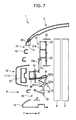
- FIG. 6 is a view illustrating an outline of operation of the variable duct apparatus according to this embodiment when admission of outside air is required;
- FIG. 9 is an exploded perspective view similarly illustrating a schematic of the structure of a lower link in the variable duct apparatus according to this embodiment.
- FIG. 10 is a view illustrating an outline of operation of the variable duct apparatus according to this embodiment when admission of outside air is required;
- FIG. 11 is a view illustrating an outline of operation of the variable duct apparatus according to this embodiment during running of a vehicle on a flooded road or the like.
- FIG. 12 is a view illustrating an outline of a variable duct apparatus according to the related art.
- FIG. 1 is a perspective view of the front portion of a vehicle equipped with a variable duct apparatus according to this embodiment.
- FIG. 2 is a view taken in the direction of an arrow A in FIG. 1 .
- FIG. 3 is a cross-sectional view taken along a line III-III of FIG. 2 .
- FIG. 4 is an exploded perspective view illustrating an outline of the structure of a lower link in the variable duct apparatus.
- FIG. 5 is a view illustrating an outline of a lower link bracket.
- an arrow F indicates the vehicle's forward direction
- an arrow R indicates the vehicle's rearward direction.
- an engine compartment 2 is formed at the front portion of the vehicle 1 , and the engine compartment 2 is covered by a hood 3 at the top in such a way as to allow its opening and closing.
- a cooler condenser 4 and a radiator 5 are mounted via a bracket or the like to a radiator upper panel and a radiator lower panel (not shown) which extend in the vehicle width direction.
- a bumper 10 extending in the vehicle width direction is arranged in a lower part of the front portion of the vehicle 1 , and a front grille 18 extending in the vehicle width direction is arranged in an upper part of the front portion of the vehicle 1 .
- the bumper 10 includes a bumper upper portion 11 and a bumper lower portion 14 arranged below the bumper upper portion 11 .
- the bumper upper portion 11 includes a bumper beam 12 extending in the vehicle width direction and supported on a vehicle body frame (not shown).
- a bumper face 13 made of resin is mounted to the front side of the bumper beam 12 via an impact absorber (not shown).
- the bumper lower portion 14 is formed by an impact absorbing member (not shown) interposed between the radiator lower panel and the bumper face 13 .
- the height dimension of the bumper lower portion 14 in the vertical direction is smaller than the height dimension of the bumper upper portion 11 in the vertical direction, and the front end of the bumper lower portion 14 is located more rearward in the vehicle than the front end of the bumper upper portion 11 .
- An air inlet 15 serving as the lower opening is formed between the bumper upper portion 11 and the bumper lower portion 14 .
- the front grille 18 is formed between the bumper upper portion 11 and the front end of the hood 3 , and has a grille opening 19 having a decorative function and serving as the upper opening that admits outside air.
- a variable duct apparatus 20 that controls outside air flowing in to the radiator 5 is disposed between the bumper 10 and the front grille 18 , and the radiator 5 .
- variable duct apparatus 20 Next, the variable duct apparatus 20 will be described.
- the variable duct apparatus 20 has stationary louvers 22 and variable louvers 23 provided between the grille opening 19 of the front grille 18 and the radiator 5 , and a lower louver 25 provided between the air inlet 15 of the bumper 10 and the radiator 5 .
- the variable louvers 23 and the lower louver 25 are connected to each other by a link mechanism 30 .
- the stationary louvers 22 are flat and formed in a substantially rectangular shape so as to extend in the vehicle width direction, and are supported in a stationary fashion at the upper end and lower end of the grille opening 19 .
- a plurality of movable louvers 23 which in this embodiment are three movable louvers 23 , are disposed between the stationary louver 22 that is arranged at the upper end between the grille opening 19 and the radiator 5 , and the stationary louver 22 that is arranged at the lower end.
- the variable louvers 23 each include a blocking surface 23 b .
- the blocking surface 23 b are flat and formed in a substantially rectangular shape so as to extend in the vehicle width direction.
- a rotating shaft 23 a is inserted into an insertion hole formed so as to extend through each of the variable louvers 23 in the vehicle width direction from the substantially central portion along the direction of the short side of the blocking surface 23 b .
- the variable louvers 23 are each supported on the rotating shaft 23 a so as to be rotatable with respect to the stationary louver 22 .
- a plate-shaped drive receiving portion 23 c is formed so as to project from one side of the blocking surface 23 b .
- the blocking surface 23 b and the drive receiving portion 23 c are formed integrally to constitute each of the variable louvers 23 .
- the variable louvers 23 described above swing between the grille opening 19 and the radiator 5 to block or allow communication between the grille opening 19 and the radiator 5 , thereby adjusting the amount of outside air admitted to the radiator 5 from the grille opening 19 .
- the lower louver 25 includes a blocking surface 25 a .
- the blocking surface 25 a has a proximal end 25 b arranged on the side toward the upper portion of the vehicle 1 , and a distal end 25 c arranged on the side toward the lower portion of the vehicle 1 .
- the blocking surface 25 a has a wing-shaped cross-section that curves while gradually decreasing in thickness from the proximal end 25 b toward the distal end 25 c .
- the blocking surface 25 a is formed with such a cross-sectional shape extending along the vehicle width direction.
- a hinge 25 d having an insertion hole that extends through the lower louver 25 in the vehicle width direction is formed at the proximal end 25 b .
- a rotating shaft 25 e is inserted into the insertion hole of the hinge 25 d .
- the lower louver 25 is pivotally supported on a vehicle body member (not shown) by the rotating shaft 25 e.
- a lower-link-arm engaging portion 25 f formed like a substantially chevron-shaped column in cross-section is formed so as to project from the distal end 25 c side of the curved inner side of the blocking surface 25 a .
- Engaging holes 25 g for engagement with a lower link arm 35 described later are bored in opposite side surfaces of the lower-link-arm engaging portion 25 f .
- the blocking surface 25 a and the lower-link-arm engaging portion 25 f are formed integrally to constitute the lower louver 25 .
- the lower louver 25 described above opens and closes between the air inlet 15 and the radiator 5 , thereby blocking or allowing communication between the air inlet 15 and the radiator 5 to adjust the amount of outside air admitted to the radiator 5 .
- the link mechanism 30 includes an upper link 31 and lower link 32 , and a link base portion 33 that connects and drives these links together.
- the link base portion 33 is formed in a flat, substantially rectangular shape having one end 33 a and the other end 33 b .
- a fitting hole 33 c is formed at substantially the central portion of the link base portion 33 .
- a rotating shaft 41 a of an actuator 41 is fitted into the fitting hole 33 c .
- the link base portion 33 is mounted to the vehicle body member (not shown) via a mounting bracket 40 having a hat-shaped cross-section to which the actuator 41 is mounted.
- the upper link 31 includes an upper first rod 31 a and an upper second rod 31 b formed in a rod-like shape and extending in the vertical direction on the side of the vehicle's forward direction F with respect to each of the variable louvers 23 .
- a drive shaft 31 c connected to the drive receiving portion 23 c of each of the variable louvers 23 is formed on the upper first rod 31 a .
- the upper part of the upper second rod 31 b is pivoted on the lower part of the upper first rod 31 a , and the lower part of the upper second rod 31 b is rotatably mounted to the one end 33 a of the link base portion 33 .
- the lower link 32 includes a lower link bracket 34 , a lower link arm 35 , and a spring 36 .
- the lower link bracket 34 has a mounting portion 34 A that is opposed to the link base portion 33 and mounted to the other end 33 b of the link base portion 33 , a general surface 34 B that is bent and extends in the vehicle's rearward direction R from the mounting portion 34 A, and a guide portion 34 D that branches off up and down from an end portion 34 C of the general surface 34 B and extends in the vehicle's rearward direction R so as to have a substantially Y-shape in side view.
- the guide portion 34 D includes a fitting portion 34 E, and a first guide piece 34 Da having a first slanting portion 34 Db and a first flat portion 34 Dc.
- the fitting portion 34 E is formed so as to be recessed toward the vehicle's forward direction F from substantially the central portion in the vertical direction at the end portion 34 C of the general surface 34 B.
- the first slanting portion 34 Db slants upwards continuously from the upper portion of the fitting portion 34 E and extends toward the vehicle's rearward direction R.
- the first flat portion 34 Dc is bent and extends toward the vehicle's rearward direction R from the first slanting portion 34 Db.
- the guide portion 34 D includes a second guide piece 34 Dd having a second slanting portion 34 De and a second flat portion 34 Df.
- the second slanting portion 34 De slants and extends downwards continuously from the lower portion of the fitting portion 34 E so as to gradually move away from the first guide piece 34 Da.
- the second flat portion 34 Df is bent and extends toward the vehicle's rearward direction R from the second slanting portion 34 De.
- the lower link arm 35 is formed by a rod-like member, and has a linear upper portion 35 e capable of engagement with the fitting portion 34 E of the lower link bracket 34 and extending in the vehicle width direction.
- the lower link arm 35 has side portions 35 c and 35 d that are bent downwards from the opposite ends of the upper portion 35 e and extend while being opposed to each other. End portions 35 a and 35 b are respectively bent from the side portions 35 c and 35 d in a direction toward each other, thus forming a substantially rectangular shape in plan view that is open at the lower portion with the end portions 35 a and 35 b opposed to each other at a predetermined spacing.
- the upper portion 35 e of the lower link arm 35 fits in the fitting portion 34 E of the lower link bracket 34 , and the end portions 35 a and 35 b of the lower link arm 35 are engaged with the engaging holes 25 g bored in the opposite side surfaces of the lower-link-arm engaging portion 25 f of the lower louver 25 . Furthermore, one end 36 a of the spring 36 engages with the upper portion 35 e of the lower link arm 35 , the other end 36 b of the spring 36 engages with a spring engaging portion 40 a of the mounting bracket 40 , and the lower link arm 35 is urged toward the vehicle's forward direction F so that the upper portion 35 e of the lower link arm 35 is engaged with and held by the fitting portion 34 E, thereby forming the lower link 32 .
- variable duct apparatus 20 Next, a description will be given of operation of the variable duct apparatus 20 according to this embodiment with reference to FIGS. 3 , 6 and 7 .
- variable louvers 23 are each caused to swing about the drive receiving portion 23 c by the drive shaft 31 c formed on the upper first rod 31 a and connected to the drive receiving portion 23 c of each of the variable louvers 23 , thereby blocking communication between the grille opening 19 and the radiator 5 .
- the grille opening 19 and the radiator 5 , and the air inlet 15 and the radiator 5 are both caused to communicate with each other in a synchronized fashion so as to admit outside air to the radiator 5 from the air inlet 15 formed in the bumper 10 and from the grille opening 19 formed in the front grille 18 . That is, in this embodiment, in the state when communication between the grille opening 19 and the radiator 5 and communication between the air inlet 15 and the radiator 5 are blocked, the actuator 41 is allowed to move, causing the one end 33 a side and the other end 33 b side of the link base portion 33 of the link mechanism 30 to rotate downwards and upwards, respectively.
- variable louvers 23 are each caused to swing about the drive receiving portion 23 c by the drive shaft 31 c formed on the upper first rod 31 a and connected to the drive receiving portion 23 c of each of the variable louvers 23 , thereby allowing communication between the grille opening 19 and the radiator 5 .
- the drive force produced by the rotation of the link base portion 33 is transmitted to the lower link bracket 34 of the lower link 32 connected to the other end 33 b side. Consequently, the lower louver 25 connected via the lower link arm 35 that fits in the fitting portion 34 E of the lower link bracket 34 is pulsed upwards from the distal end 25 c side and caused to swing about the hinge 25 d , thereby allowing communication between the air inlet 15 and the radiator 5 .
- variable duct apparatus 20 when the vehicle 1 shifts to running on a flooded road.
- the upper portion 35 e of the lower link arm 35 thus shifts toward the vehicle's rearward direction R along the first guide piece 34 Da of the lower link bracket 34 , against the urging force applied by the spring 36 in the vehicle's forward direction F.
- variable duct apparatus 20 when the lower louver 25 freezes.
- the lower louver 25 of the vehicle 1 becomes inoperative due to an external force, that is, if the lower louver 25 freezes in the state where communication between the grille opening 19 and the radiator 5 and communication between the air inlet 15 and the radiator 5 are both blocked in a synchronized fashion, when the engine becomes a high-temperature combustion state or the like and the actuator 41 is allowed to move, the one end 33 a side and the other end 33 b side of the link base portion 33 of the link mechanism 30 rotate downwards and upwards, respectively. This allows communication between the grille opening 19 and the radiator 5 .
- the link base portion 33 of the link mechanism 30 is rotated by a single actuator 41 , and the drive force due to the rotation is transmitted to the upper link 31 and the lower link 32 , so the variable louvers 23 and the lower louver 25 operate in coordination with each other. That is, when admission of outside air is required during high-temperature engine combustion or the like, the variable louvers 23 and the lower louver 25 both swing to allow communication between the grille opening 19 and the radiator 5 and communication between the air inlet 15 and the radiator 5 , respectively. When admission of outside air is not required for the vehicle 1 , the variable louvers 23 and the lower louver 25 both swing to block communication between the grille opening 19 and the radiator 5 and communication between the air inlet 15 and the radiator 5 , respectively.
- the number of members is reduced to achieve a reduction in manufacturing cost and a reduction in weight, and furthermore, when admission of outside air is required, outside air can be efficiently admitted from the grille opening 19 and the air inlet 15 to cool the cooler condenser 4 and the engine coolant in the radiator 5 . Also, when admission of outside air is not required, admission of outside air from the grille opening 19 and the air inlet 15 can be reliably blocked to prevent excessive cooling of the engine, and also a reduction in fuel efficiency due to an increase in running resistance can be prevented.
- the portion of the lower louver 25 freezes in the state where communication between the grille opening 19 and the radiator 5 and communication between the air inlet 15 and the radiator 5 are blocked, when the engine burns at high temperature, the grille opening 19 and the radiator 5 are caused to communicate with each other.
- the fitting between the lower link bracket 34 and the lower link arm 35 is released by the rotation of the link base portion 33 , causing the lower link arm 35 to shift toward the vehicle's rearward direction R along the second guide piece 34 Db of the lower link bracket 34 . Therefore, when the lower louver 25 is inoperative, the coordination between the variable louvers 23 and the lower louver 25 is interrupted, thereby ensuring independent operation of the variable louvers 23 .
- variable louvers 23 and the lower louver 25 and interruption of the coordination can be realized by means of a simple mechanical structure, and the link mechanism 30 can be moved by the single actuator 41 . It is thus possible to cut down manufacturing cost, and also reduce the weight of the vehicle 1 and the risk of failure.
- FIG. 8 is a view illustrating an outline of the lower portion of a variable duct apparatus 50 according to the second embodiment.
- FIG. 9 is an exploded structural view of the lower portion of the variable duct apparatus 50 .
- an arrow F indicates the vehicle's forward direction
- an arrow R indicates the vehicle's rearward direction.
- elements that are the same as those in FIGS. 1 to 7 are denoted by the same symbols, and a detailed description of those elements is omitted.
- a lower louver 61 having the blocking surface 25 a between the air inlet 15 of the bumper 10 and the radiator 5 .
- the blocking surface 25 a of the lower louver 61 is of the same structure as the blocking surface 25 a of the lower louver 25 according to the first embodiment.
- the lower louver 61 is disposed in the vehicle body member in the same placement as the lower louver 25 , and is connected by a link mechanism 70 .
- the lower louver 61 described above swings between the air inlet 15 and the radiator 5 to block or allow communication between the air inlet 15 and the radiator 5 , thereby adjusting the amount of outside air admitted to the radiator 5 from the air inlet 15 .
- the link mechanism 70 includes a rod 71 , an engaging portion 72 formed in the lower louver 61 , and a lower rotary link member 73 .
- the rod 71 has a rod main body portion 71 a formed in a rod-like shape, and a distal end portion 71 c formed with a small diameter relative to the rod main body portion 71 a and in a rod-like shape so as to extend from an end portion 71 b of the rod main body portion 71 a .
- a drive shaft (not shown) connected to the drive receiving portion 23 c of each of the variable louvers 23 (not shown in FIG. 8 ) is formed at an upper portion of the rod 71 serving as the proximal end.
- the engaging portion 72 is formed by arranging two plate-like members on the side of the vehicle's rearward direction of the lower louver 61 , oppose to each other.
- the two plate-like members each have an upper edge 72 a and a side edge 72 b and are formed in a substantially strip shape in side view.
- a fitting portion 72 c having a substantially recessed shape in side view is formed at substantially the central portion of the upper edge 72 a of each of the two plate-like members constituting the engaging portion 72 .
- the engaging portion 72 is formed integrally with the lower louver 61 .
- the lower rotary link member 73 has a rotating shaft 73 a , a lower-rotary-link-main-body first surface 73 b , a weight 73 c , a fitting shaft portion 73 d , a lower-rotary-link-main-body second surface 73 e , a lower rod engaging hole 73 f , and a water receiving portion 73 g , and is formed in a substantially T shape in side view.
- the rotating shaft 73 a has a hollow cylindrical shape and extends in the vehicle body width direction W.
- the lower-rotary-link-main-body first surface 73 b is formed in a flat shape extending toward the vehicle's forward direction F from the rotating shaft 73 a .
- the weight 73 c serves as urging means that extends in the vehicle body width direction W and formed in a substantially cubic shape at the distal end of the lower-rotary-link-main-body first surface 73 b .
- the fitting shaft portion 73 d has a cylindrical shape and formed at the distal end of an extended portion that extends in the vehicle body width direction W on the lower side of the lower-rotary-link-main-body first surface 73 b and projects downwards from this lower side.
- the lower-rotary-link-main-body second surface 73 e extends toward the vehicle's rearward direction R from the rotating shaft 73 a and is formed in a flat shape.
- the lower rod engaging hole 73 f is bored in the lower-rotary-link-main-body second surface 73 e and formed as an elongated hole by being chamfered at the edges.
- the water receiving portion 73 g is provided upright from the rotating shaft 73 a orthogonally to the lower-rotary-link-main-body first surface 73 b and the lower-rotary-link-main-body second surface 73 e , and has a rod guide 73 h formed by cutting out the substantially central portion in the vehicle body width direction W of the upper edge into a rectangular shape.
- the drive shaft formed at the upper portion of the rod 71 is connected to the drive receiving portion 23 c of each of the variable louvers 23 , and the lower rotary link member 73 is rotatably pivoted on a vehicle body member (not shown) by the rotating shaft 73 a .
- the drive shaft (not shown) formed at the upper portion of the rod 71 is connected to the drive receiving portion 23 c of each of the variable louvers 23 , and the distal end portion 71 c of the rod 71 is inserted into the lower rod engaging hole 73 f bored in the lower-rotary-link-main-body second surface 73 e of the lower rotary link member 73 , causing the end portion 71 b of the rod main body portion 71 a to abut on the lower-rotary-link-main-body second surface 73 e .
- the grille opening 19 and the radiator 5 , and the air inlet 15 and the radiator 5 are both caused to communicate with each other in a synchronized fashion so as to admit outside air to the radiator 5 from the air inlet 15 formed in the bumper 10 and from the grille opening 19 formed in the front grille 18 . That is, in this embodiment, in the state when communication between the grille opening 19 and the radiator 5 and communication between the air inlet 15 and the radiator 5 are blocked, as an actuator (not shown) is allowed to move, the rod 71 descends. This causes the grille opening 19 and the radiator 5 to communicate with each other.
- the lower rotary link member 73 rotates downwards from the weight 73 c side about the rotating shaft 73 a due to the self weight of the weight 73 c of the lower rotary link member 73 .
- the fitting shaft portion 73 d fits in the fitting portion 72 c , causing the lower louver 61 to stop in closing position, thereby blocking communication between the air inlet 15 and the radiator 5 .
Landscapes
- Engineering & Computer Science (AREA)
- Chemical & Material Sciences (AREA)
- Combustion & Propulsion (AREA)
- Transportation (AREA)
- Mechanical Engineering (AREA)
- Cooling, Air Intake And Gas Exhaust, And Fuel Tank Arrangements In Propulsion Units (AREA)
- Air-Conditioning For Vehicles (AREA)
Abstract
Description
Claims (11)
Applications Claiming Priority (2)
| Application Number | Priority Date | Filing Date | Title |
|---|---|---|---|
| JP2009-245107 | 2009-10-26 | ||
| JP2009245107A JP5620085B2 (en) | 2009-10-26 | 2009-10-26 | Variable duct device |
Publications (2)
| Publication Number | Publication Date |
|---|---|
| US20110097984A1 US20110097984A1 (en) | 2011-04-28 |
| US8814638B2 true US8814638B2 (en) | 2014-08-26 |
Family
ID=43796950
Family Applications (1)
| Application Number | Title | Priority Date | Filing Date |
|---|---|---|---|
| US12/923,886 Active 2033-05-12 US8814638B2 (en) | 2009-10-26 | 2010-10-13 | Variable duct apparatus |
Country Status (4)
| Country | Link |
|---|---|
| US (1) | US8814638B2 (en) |
| JP (1) | JP5620085B2 (en) |
| CN (1) | CN102050008B (en) |
| DE (1) | DE102010038194A1 (en) |
Cited By (9)
| Publication number | Priority date | Publication date | Assignee | Title |
|---|---|---|---|---|
| US20120097464A1 (en) * | 2010-10-22 | 2012-04-26 | Gm Global Technology Operations, Inc. | Control of a shutter via bi-directional communication using a single wire |
| US20150041229A1 (en) * | 2013-08-08 | 2015-02-12 | Honda Motor Co., Ltd. | Front end arrangement with active radiator damper and active radiator control method |
| US20180080367A1 (en) * | 2016-09-22 | 2018-03-22 | Trent Mallett | Engine shield |
| US10071625B1 (en) | 2017-08-15 | 2018-09-11 | Ford Global Technologies, Llc | Flow control assembly and method utilizing apertured shutters |
| US10166859B1 (en) * | 2017-06-30 | 2019-01-01 | GM Global Technology Operations LLC | Active underbody arrangement for a vehicle |
| US20220194214A1 (en) * | 2019-05-17 | 2022-06-23 | Bayerische Motoren Werke Aktiengesellschaft | Air Inlet Arrangement |
| US11370295B2 (en) * | 2019-05-15 | 2022-06-28 | Röchling Automotive SE & Co. KG | OBD-capable air-flap apparatus |
| US20220371430A1 (en) * | 2019-07-03 | 2022-11-24 | Hbpo Gmbh | Device for Closing a Motor Vehicle Cooling Module |
| US11813937B2 (en) | 2020-03-31 | 2023-11-14 | Röchling Automotive SE | Air flap apparatus having asynchronously movable air flap arrays |
Families Citing this family (68)
| Publication number | Priority date | Publication date | Assignee | Title |
|---|---|---|---|---|
| JP3018139B2 (en) | 1994-11-09 | 2000-03-13 | 新日本製鐵株式会社 | Shape steel rolling mill |
| FR2950574B1 (en) * | 2009-09-29 | 2012-03-23 | Valeo Systemes Thermiques | THERMAL EXCHANGE BLOCK FOR MOTOR VEHICLE |
| US8998293B2 (en) * | 2010-06-22 | 2015-04-07 | Ford Global Technologies, Llc | Airflow control device for an automotive vehicle |
| US8646552B2 (en) * | 2010-07-21 | 2014-02-11 | Shape Corp. | Integrated energy absorber and air flow management structure |
| DE102011102155A1 (en) * | 2011-05-20 | 2012-11-22 | GM Global Technology Operations LLC (n. d. Gesetzen des Staates Delaware) | Radiator grill module for cooling radiator in body space of front end portion of motor car, has air-guidance elements redirecting part of airflow into body space region between bumper and radiator, and designed as slat-form surface elements |
| US8807166B2 (en) * | 2011-06-03 | 2014-08-19 | GM Global Technology Operations LLC | Active aero shutters |
| JP5668610B2 (en) * | 2011-06-10 | 2015-02-12 | カルソニックカンセイ株式会社 | Water-cooled condenser |
| US8892314B2 (en) | 2011-06-15 | 2014-11-18 | GM Global Technology Operations LLC | Rejection of under-hood airflow |
| KR20130007831A (en) * | 2011-07-11 | 2013-01-21 | 현대모비스 주식회사 | Airflap apparatus for an automobile |
| JP6053269B2 (en) * | 2011-09-13 | 2016-12-27 | 本田技研工業株式会社 | Motorcycle cooling system with unit swing internal combustion engine |
| JP5807486B2 (en) * | 2011-09-28 | 2015-11-10 | アイシン精機株式会社 | Grill shutter device |
| US20130081888A1 (en) * | 2011-09-30 | 2013-04-04 | GM Global Technology Operations LLC | Reconfigurable baseline opening for under-hood airflow |
| DE102011085074A1 (en) * | 2011-10-24 | 2013-04-25 | Ford Global Technologies, Llc | Front end module for e.g. passenger car, has radiator carrier comprising air passage apertures for supplying air to radiator, and radiator closing device is arranged in front region of radiator and designed as part of module |
| US20130103265A1 (en) * | 2011-10-25 | 2013-04-25 | GM Global Technology Operations LLC | Vehicle grille shutter |
| DE102011055394A1 (en) * | 2011-11-15 | 2013-05-16 | Brose Fahrzeugteile Gmbh & Co. Kommanditgesellschaft, Coburg | Air valve assembly for controlling flow of cooling air in engine compartment of vehicle, has actuating element and valve elements that are moved in non-synchronous manner using driving device |
| CN103121427B (en) * | 2011-11-18 | 2016-01-13 | 北汽福田汽车股份有限公司 | Adjustable automobile air grid system and automobile |
| KR101371455B1 (en) * | 2011-12-09 | 2014-03-11 | 현대자동차주식회사 | Air conditioner cooling system for vehicle |
| US9714602B2 (en) * | 2012-03-16 | 2017-07-25 | Honda Motor Co., Ltd. | Airflow directing member for a vehicle engine compartment |
| DE102012010891B4 (en) | 2012-06-01 | 2014-08-07 | Audi Ag | Controllable cooling air intake for a vehicle |
| JP5497866B2 (en) * | 2012-09-27 | 2014-05-21 | 富士重工業株式会社 | Mounting structure for opening adjustment device |
| CA2887282C (en) * | 2012-10-24 | 2020-07-14 | Maralto Environmental Technologies Ltd. | Heat exchanger and method for heating a fracturing fluid |
| US8733484B1 (en) | 2012-12-13 | 2014-05-27 | Ford Global Technologies, Llc | Linkage for dual grille shutter system |
| US10029558B2 (en) * | 2013-03-15 | 2018-07-24 | Srg Global, Inc. | Grille shutter assembly |
| JP5458200B1 (en) * | 2013-03-28 | 2014-04-02 | 富士重工業株式会社 | Variable duct device for vehicle |
| KR101481270B1 (en) * | 2013-05-22 | 2015-01-09 | 현대자동차주식회사 | Active air flap for vehicle |
| DE102013213136A1 (en) * | 2013-07-04 | 2015-01-08 | Brose Fahrzeugteile GmbH & Co. Kommanditgesellschaft, Würzburg | Damping arrangement of a radiator-side air intake system for a motor vehicle |
| JP6083063B2 (en) * | 2013-11-22 | 2017-02-22 | トヨタ車体株式会社 | Vehicle seat latching structure |
| JP6189194B2 (en) * | 2013-11-27 | 2017-08-30 | 小島プレス工業株式会社 | Grill shutter device |
| JP6247972B2 (en) * | 2014-03-20 | 2017-12-13 | 株式会社Subaru | Vehicle movable member interlocking mechanism |
| KR101575255B1 (en) * | 2014-05-27 | 2015-12-07 | 현대자동차 주식회사 | Active air flap of vehicle |
| FR3025143B1 (en) * | 2014-08-29 | 2016-11-25 | Peugeot Citroen Automobiles Sa | MOTOR VEHICLE WITH IMPROVED REPARABILITY |
| JP6235438B2 (en) * | 2014-09-10 | 2017-11-22 | 本田技研工業株式会社 | Forced air-cooled internal combustion engine |
| KR101567733B1 (en) * | 2014-11-12 | 2015-11-10 | 현대자동차주식회사 | External type active air flap apparatus for vehicle |
| DE102014226027A1 (en) * | 2014-12-16 | 2016-06-16 | Bayerische Motoren Werke Aktiengesellschaft | Air supply adjusting device for a motor vehicle |
| DE102014226028A1 (en) * | 2014-12-16 | 2016-06-16 | Bayerische Motoren Werke Aktiengesellschaft | Air supply adjusting device for a motor vehicle |
| JP6155249B2 (en) | 2014-12-26 | 2017-06-28 | 株式会社ファルテック | Grill shutter module |
| US10252611B2 (en) * | 2015-01-22 | 2019-04-09 | Ford Global Technologies, Llc | Active seal arrangement for use with vehicle condensers |
| DE102015109698B4 (en) * | 2015-06-17 | 2021-06-24 | Hbpo Gmbh | Cooling system for a vehicle |
| FR3039102B1 (en) * | 2015-07-22 | 2017-07-21 | Valeo Systemes Thermiques | DEVICE FOR SHUTTING OFF AIR INTAKE, ESPECIALLY POSITIONED ON THE FRONT PANEL OF A VEHICLE SUCH AS A MOTOR VEHICLE |
| US9840144B2 (en) * | 2015-08-19 | 2017-12-12 | Mazda Motor Corporation | Front air-rectifying structure of automotive vehicle |
| KR101655700B1 (en) * | 2015-09-21 | 2016-09-07 | 현대자동차주식회사 | Active air flap apparatus for improving side sealing performance |
| KR101724907B1 (en) * | 2015-09-21 | 2017-04-10 | 현대자동차주식회사 | Apparatus for improving aerodynamic characteristics of vehicle |
| JP6566817B2 (en) * | 2015-09-29 | 2019-08-28 | 株式会社クボタ | Work vehicle |
| DE102015221003B4 (en) * | 2015-10-27 | 2022-02-03 | Bayerische Motoren Werke Aktiengesellschaft | Air supply adjustment device for a motor vehicle |
| FR3060478B1 (en) * | 2016-12-16 | 2019-01-25 | Peugeot Citroen Automobiles Sa. | AIR INTAKE ADJUSTMENT DEVICE |
| FR3066445B1 (en) * | 2017-05-19 | 2019-05-03 | Valeo Systemes Thermiques | DEVICE FOR CONTROLLING AN AIR FLOW OF AN AIR INTAKE FOR THE FRONT OF A VEHICLE |
| JP6455557B2 (en) * | 2017-06-30 | 2019-01-23 | マツダ株式会社 | Automobile grill shutter mounting structure |
| JP6879175B2 (en) * | 2017-11-14 | 2021-06-02 | トヨタ自動車株式会社 | Grill shutter device |
| KR102452713B1 (en) * | 2017-12-29 | 2022-10-11 | 현대자동차주식회사 | Air Guide Structure of Vehicle |
| KR102598528B1 (en) * | 2018-05-16 | 2023-11-03 | 현대자동차주식회사 | Motor driven air vent device for vehicle |
| DE102018211425A1 (en) * | 2018-07-10 | 2020-01-16 | Volkswagen Aktiengesellschaft | Cooling system for a motor vehicle with cover devices for influencing the supply of cooling air to coolant coolers |
| JP7014082B2 (en) * | 2018-07-31 | 2022-02-01 | 豊田合成株式会社 | Grill shutter control device |
| JP2020040630A (en) * | 2018-09-13 | 2020-03-19 | いすゞ自動車株式会社 | Air guide structure |
| EP3626499B1 (en) * | 2018-09-18 | 2021-07-21 | Volvo Car Corporation | Vehicle front structure |
| EP3643551B1 (en) * | 2018-10-24 | 2021-06-23 | Batz, S.Coop. | Shutter device for a front grille of a vehicle |
| JP2020196367A (en) * | 2019-06-04 | 2020-12-10 | 本田技研工業株式会社 | Front end structure |
| JP7316119B2 (en) * | 2019-07-03 | 2023-07-27 | 株式会社Subaru | electric car air conditioning system |
| CN110877524B (en) * | 2019-12-04 | 2021-09-21 | 武汉理工大学 | Rotatable cooling module in engine compartment |
| US12409724B2 (en) | 2020-02-19 | 2025-09-09 | Hanon Systems | Air flap having mixed-type door structure |
| CN111409447B (en) * | 2020-03-09 | 2021-05-18 | 浙江零跑科技有限公司 | a car air intake |
| DE102021101127A1 (en) | 2020-03-19 | 2021-09-23 | Hanon Systems | System for air conditioning the air in a passenger compartment and for heat transfer with drive components of a motor vehicle and a method for operating the system |
| JP7567283B2 (en) * | 2020-08-24 | 2024-10-16 | 株式会社デンソー | Vehicle shutter device |
| KR102789603B1 (en) * | 2020-09-11 | 2025-04-01 | 현대모비스 주식회사 | Active Air Flap Apparatus For Vehicle |
| JP6932832B1 (en) * | 2020-11-19 | 2021-09-08 | マレリ株式会社 | Flap door |
| CN112855350A (en) * | 2021-02-05 | 2021-05-28 | 北京北航天宇长鹰无人机科技有限公司 | Aircraft and radiator grille thereof |
| EP4169755B1 (en) | 2021-10-19 | 2024-12-11 | Audi AG | Radiator arrangement for a vehicle and vehicle |
| CN115320365B (en) * | 2022-08-18 | 2025-04-22 | 江苏菱盛汽配科技有限公司 | Automobile front windshield radiator shutter structure |
| KR20240140571A (en) * | 2023-03-17 | 2024-09-24 | 현대모비스 주식회사 | Lighting device for vehicle |
Citations (9)
| Publication number | Priority date | Publication date | Assignee | Title |
|---|---|---|---|---|
| US1570111A (en) * | 1924-08-18 | 1926-01-19 | Wickware Walter Halpenny | Shutter mechanism for automobile radiators |
| US1619621A (en) * | 1927-03-01 | Radiator-shutter | ||
| US4457558A (en) * | 1981-04-22 | 1984-07-03 | Aisin Seiki Kabushiki Kaisha | Up and down moving mechanism for an air spoiler associated with a movable grill |
| JPS6217313A (en) * | 1985-07-15 | 1987-01-26 | Nissan Motor Co Ltd | Radiator shutter |
| JPH0558172A (en) | 1991-08-27 | 1993-03-09 | Toyota Motor Corp | Control device for movable grill |
| US6286893B1 (en) * | 2000-01-03 | 2001-09-11 | Daimlerchrysler Corporation | Front wing with cockpit adjustment |
| US6588380B2 (en) * | 2000-04-19 | 2003-07-08 | Robert Bosch Gmbh | Cooling system for a motor vehicle comprising a closing unit for the cooling airflow |
| JP2007320527A (en) | 2006-06-05 | 2007-12-13 | Toyota Motor Corp | Vehicle cooling system |
| US20090050385A1 (en) * | 2004-10-29 | 2009-02-26 | Daimler Trucks North America Llc | Selective closing of at least one vehicle opening at a front portion of a vehicle |
Family Cites Families (3)
| Publication number | Priority date | Publication date | Assignee | Title |
|---|---|---|---|---|
| JPS58112625U (en) * | 1982-01-28 | 1983-08-01 | 三菱自動車工業株式会社 | front grill |
| JPS58139327U (en) * | 1982-03-17 | 1983-09-19 | 三菱自動車工業株式会社 | grill opening/closing device |
| CN2839024Y (en) * | 2005-10-25 | 2006-11-22 | 湖南江麓机械集团有限公司 | Air charging and discharging shutter sealing device for vehicles or ships |
-
2009
- 2009-10-26 JP JP2009245107A patent/JP5620085B2/en not_active Expired - Fee Related
-
2010
- 2010-10-13 US US12/923,886 patent/US8814638B2/en active Active
- 2010-10-14 DE DE102010038194A patent/DE102010038194A1/en not_active Withdrawn
- 2010-10-26 CN CN201010523409.3A patent/CN102050008B/en not_active Expired - Fee Related
Patent Citations (9)
| Publication number | Priority date | Publication date | Assignee | Title |
|---|---|---|---|---|
| US1619621A (en) * | 1927-03-01 | Radiator-shutter | ||
| US1570111A (en) * | 1924-08-18 | 1926-01-19 | Wickware Walter Halpenny | Shutter mechanism for automobile radiators |
| US4457558A (en) * | 1981-04-22 | 1984-07-03 | Aisin Seiki Kabushiki Kaisha | Up and down moving mechanism for an air spoiler associated with a movable grill |
| JPS6217313A (en) * | 1985-07-15 | 1987-01-26 | Nissan Motor Co Ltd | Radiator shutter |
| JPH0558172A (en) | 1991-08-27 | 1993-03-09 | Toyota Motor Corp | Control device for movable grill |
| US6286893B1 (en) * | 2000-01-03 | 2001-09-11 | Daimlerchrysler Corporation | Front wing with cockpit adjustment |
| US6588380B2 (en) * | 2000-04-19 | 2003-07-08 | Robert Bosch Gmbh | Cooling system for a motor vehicle comprising a closing unit for the cooling airflow |
| US20090050385A1 (en) * | 2004-10-29 | 2009-02-26 | Daimler Trucks North America Llc | Selective closing of at least one vehicle opening at a front portion of a vehicle |
| JP2007320527A (en) | 2006-06-05 | 2007-12-13 | Toyota Motor Corp | Vehicle cooling system |
Cited By (11)
| Publication number | Priority date | Publication date | Assignee | Title |
|---|---|---|---|---|
| US20120097464A1 (en) * | 2010-10-22 | 2012-04-26 | Gm Global Technology Operations, Inc. | Control of a shutter via bi-directional communication using a single wire |
| US20150041229A1 (en) * | 2013-08-08 | 2015-02-12 | Honda Motor Co., Ltd. | Front end arrangement with active radiator damper and active radiator control method |
| US20180080367A1 (en) * | 2016-09-22 | 2018-03-22 | Trent Mallett | Engine shield |
| US10166859B1 (en) * | 2017-06-30 | 2019-01-01 | GM Global Technology Operations LLC | Active underbody arrangement for a vehicle |
| US10071625B1 (en) | 2017-08-15 | 2018-09-11 | Ford Global Technologies, Llc | Flow control assembly and method utilizing apertured shutters |
| US11370295B2 (en) * | 2019-05-15 | 2022-06-28 | Röchling Automotive SE & Co. KG | OBD-capable air-flap apparatus |
| US20220194214A1 (en) * | 2019-05-17 | 2022-06-23 | Bayerische Motoren Werke Aktiengesellschaft | Air Inlet Arrangement |
| US12151549B2 (en) * | 2019-05-17 | 2024-11-26 | Bayerische Motoren Werke Aktiengesellschaft | Air inlet arrangement |
| US20220371430A1 (en) * | 2019-07-03 | 2022-11-24 | Hbpo Gmbh | Device for Closing a Motor Vehicle Cooling Module |
| US12240315B2 (en) * | 2019-07-03 | 2025-03-04 | Hbpo Gmbh | Device for closing a motor vehicle cooling module |
| US11813937B2 (en) | 2020-03-31 | 2023-11-14 | Röchling Automotive SE | Air flap apparatus having asynchronously movable air flap arrays |
Also Published As
| Publication number | Publication date |
|---|---|
| JP2011088584A (en) | 2011-05-06 |
| DE102010038194A1 (en) | 2011-04-28 |
| US20110097984A1 (en) | 2011-04-28 |
| CN102050008A (en) | 2011-05-11 |
| CN102050008B (en) | 2015-04-01 |
| JP5620085B2 (en) | 2014-11-05 |
Similar Documents
| Publication | Publication Date | Title |
|---|---|---|
| US8814638B2 (en) | Variable duct apparatus | |
| US8550887B2 (en) | Vehicle grill with moveable louvers | |
| US8473164B2 (en) | Shutter with offset louver pivot | |
| US9994100B1 (en) | Shutter control arrangement for a vehicle | |
| EP2335963B1 (en) | Ventilation structure for front vehicle body section | |
| US9956866B2 (en) | Active grille shutter | |
| EP3560744B1 (en) | Variable or stepped louver activation for active grille system | |
| US20130075172A1 (en) | Grille shutter device | |
| JP5342227B2 (en) | Body front structure | |
| US20120060776A1 (en) | Compound shutter system | |
| US20130252531A1 (en) | Grill shutter device | |
| US20120097465A1 (en) | System and method for controlling a shutter in a vehicle via a cooling fan duty-cycle | |
| KR101527881B1 (en) | Air flap | |
| EP3243679B1 (en) | Charge air shutter | |
| WO2016062382A1 (en) | Grille for a vehicle, in particular a commercial vehicle as well as a vehicle | |
| JP2012148705A (en) | Air intake opening and closing apparatus for vehicle | |
| KR20190012363A (en) | Grill for vehicle | |
| KR101693348B1 (en) | Active Air Flap | |
| JP6206026B2 (en) | Cooling system and control method thereof | |
| KR102598420B1 (en) | Active air flap assembly with function of tilting | |
| ES2361408T3 (en) | AIR FLOW REGULATION DEVICE FOR AN AUTOMOBILE VEHICLE COOLING MODULE. | |
| KR101626385B1 (en) | Active Air Flap | |
| KR101595979B1 (en) | Active Air Flap | |
| KR101714585B1 (en) | Front End Module | |
| KR102627795B1 (en) | Active air-flap |
Legal Events
| Date | Code | Title | Description |
|---|---|---|---|
| AS | Assignment |
Owner name: FUJI JUKOGYO KABUSHIKI KAISHA, JAPAN Free format text: ASSIGNMENT OF ASSIGNORS INTEREST;ASSIGNORS:HASEGAWA, MASAMI;YOSHIMOTO, HIROYUKI;REEL/FRAME:025198/0655 Effective date: 20100922 |
|
| STCF | Information on status: patent grant |
Free format text: PATENTED CASE |
|
| AS | Assignment |
Owner name: FUJI JUKOGYO KABUSHIKI KAISHA, JAPAN Free format text: CHANGE OF ADDRESS;ASSIGNOR:FUJI JUKOGYO KABUSHIKI KAISHA;REEL/FRAME:034215/0580 Effective date: 20140818 |
|
| FEPP | Fee payment procedure |
Free format text: PAYOR NUMBER ASSIGNED (ORIGINAL EVENT CODE: ASPN); ENTITY STATUS OF PATENT OWNER: LARGE ENTITY |
|
| AS | Assignment |
Owner name: SUBARU CORPORATION, JAPAN Free format text: CHANGE OF NAME;ASSIGNOR:FUJI JUKOGYO KABUSHIKI KAISHA;REEL/FRAME:042624/0886 Effective date: 20170401 |
|
| MAFP | Maintenance fee payment |
Free format text: PAYMENT OF MAINTENANCE FEE, 4TH YEAR, LARGE ENTITY (ORIGINAL EVENT CODE: M1551) Year of fee payment: 4 |
|
| MAFP | Maintenance fee payment |
Free format text: PAYMENT OF MAINTENANCE FEE, 8TH YEAR, LARGE ENTITY (ORIGINAL EVENT CODE: M1552); ENTITY STATUS OF PATENT OWNER: LARGE ENTITY Year of fee payment: 8 |