US8655530B2 - Parking assist device for vehicle and electrically powered vehicle including the same - Google Patents
Parking assist device for vehicle and electrically powered vehicle including the same Download PDFInfo
- Publication number
- US8655530B2 US8655530B2 US13/142,429 US201013142429A US8655530B2 US 8655530 B2 US8655530 B2 US 8655530B2 US 201013142429 A US201013142429 A US 201013142429A US 8655530 B2 US8655530 B2 US 8655530B2
- Authority
- US
- United States
- Prior art keywords
- vehicle
- power
- reception unit
- power transmission
- transmission unit
- Prior art date
- Legal status (The legal status is an assumption and is not a legal conclusion. Google has not performed a legal analysis and makes no representation as to the accuracy of the status listed.)
- Active
Links
Images


Classifications
-
- B—PERFORMING OPERATIONS; TRANSPORTING
- B60—VEHICLES IN GENERAL
- B60K—ARRANGEMENT OR MOUNTING OF PROPULSION UNITS OR OF TRANSMISSIONS IN VEHICLES; ARRANGEMENT OR MOUNTING OF PLURAL DIVERSE PRIME-MOVERS IN VEHICLES; AUXILIARY DRIVES FOR VEHICLES; INSTRUMENTATION OR DASHBOARDS FOR VEHICLES; ARRANGEMENTS IN CONNECTION WITH COOLING, AIR INTAKE, GAS EXHAUST OR FUEL SUPPLY OF PROPULSION UNITS IN VEHICLES
- B60K6/00—Arrangement or mounting of plural diverse prime-movers for mutual or common propulsion, e.g. hybrid propulsion systems comprising electric motors and internal combustion engines ; Control systems therefor, i.e. systems controlling two or more prime movers, or controlling one of these prime movers and any of the transmission, drive or drive units Informative references: mechanical gearings with secondary electric drive F16H3/72; arrangements for handling mechanical energy structurally associated with the dynamo-electric machine H02K7/00; machines comprising structurally interrelated motor and generator parts H02K51/00; dynamo-electric machines not otherwise provided for in H02K see H02K99/00
- B60K6/20—Arrangement or mounting of plural diverse prime-movers for mutual or common propulsion, e.g. hybrid propulsion systems comprising electric motors and internal combustion engines ; Control systems therefor, i.e. systems controlling two or more prime movers, or controlling one of these prime movers and any of the transmission, drive or drive units Informative references: mechanical gearings with secondary electric drive F16H3/72; arrangements for handling mechanical energy structurally associated with the dynamo-electric machine H02K7/00; machines comprising structurally interrelated motor and generator parts H02K51/00; dynamo-electric machines not otherwise provided for in H02K see H02K99/00 the prime-movers consisting of electric motors and internal combustion engines, e.g. HEVs
- B60K6/42—Arrangement or mounting of plural diverse prime-movers for mutual or common propulsion, e.g. hybrid propulsion systems comprising electric motors and internal combustion engines ; Control systems therefor, i.e. systems controlling two or more prime movers, or controlling one of these prime movers and any of the transmission, drive or drive units Informative references: mechanical gearings with secondary electric drive F16H3/72; arrangements for handling mechanical energy structurally associated with the dynamo-electric machine H02K7/00; machines comprising structurally interrelated motor and generator parts H02K51/00; dynamo-electric machines not otherwise provided for in H02K see H02K99/00 the prime-movers consisting of electric motors and internal combustion engines, e.g. HEVs characterised by the architecture of the hybrid electric vehicle
- B60K6/44—Series-parallel type
- B60K6/445—Differential gearing distribution type
-
- B—PERFORMING OPERATIONS; TRANSPORTING
- B60—VEHICLES IN GENERAL
- B60L—PROPULSION OF ELECTRICALLY-PROPELLED VEHICLES; SUPPLYING ELECTRIC POWER FOR AUXILIARY EQUIPMENT OF ELECTRICALLY-PROPELLED VEHICLES; ELECTRODYNAMIC BRAKE SYSTEMS FOR VEHICLES IN GENERAL; MAGNETIC SUSPENSION OR LEVITATION FOR VEHICLES; MONITORING OPERATING VARIABLES OF ELECTRICALLY-PROPELLED VEHICLES; ELECTRIC SAFETY DEVICES FOR ELECTRICALLY-PROPELLED VEHICLES
- B60L53/00—Methods of charging batteries, specially adapted for electric vehicles; Charging stations or on-board charging equipment therefor; Exchange of energy storage elements in electric vehicles
- B60L53/10—Methods of charging batteries, specially adapted for electric vehicles; Charging stations or on-board charging equipment therefor; Exchange of energy storage elements in electric vehicles characterised by the energy transfer between the charging station and the vehicle
- B60L53/12—Inductive energy transfer
- B60L53/126—Methods for pairing a vehicle and a charging station, e.g. establishing a one-to-one relation between a wireless power transmitter and a wireless power receiver
-
- B—PERFORMING OPERATIONS; TRANSPORTING
- B60—VEHICLES IN GENERAL
- B60L—PROPULSION OF ELECTRICALLY-PROPELLED VEHICLES; SUPPLYING ELECTRIC POWER FOR AUXILIARY EQUIPMENT OF ELECTRICALLY-PROPELLED VEHICLES; ELECTRODYNAMIC BRAKE SYSTEMS FOR VEHICLES IN GENERAL; MAGNETIC SUSPENSION OR LEVITATION FOR VEHICLES; MONITORING OPERATING VARIABLES OF ELECTRICALLY-PROPELLED VEHICLES; ELECTRIC SAFETY DEVICES FOR ELECTRICALLY-PROPELLED VEHICLES
- B60L53/00—Methods of charging batteries, specially adapted for electric vehicles; Charging stations or on-board charging equipment therefor; Exchange of energy storage elements in electric vehicles
- B60L53/30—Constructional details of charging stations
- B60L53/35—Means for automatic or assisted adjustment of the relative position of charging devices and vehicles
- B60L53/36—Means for automatic or assisted adjustment of the relative position of charging devices and vehicles by positioning the vehicle
-
- B—PERFORMING OPERATIONS; TRANSPORTING
- B60—VEHICLES IN GENERAL
- B60L—PROPULSION OF ELECTRICALLY-PROPELLED VEHICLES; SUPPLYING ELECTRIC POWER FOR AUXILIARY EQUIPMENT OF ELECTRICALLY-PROPELLED VEHICLES; ELECTRODYNAMIC BRAKE SYSTEMS FOR VEHICLES IN GENERAL; MAGNETIC SUSPENSION OR LEVITATION FOR VEHICLES; MONITORING OPERATING VARIABLES OF ELECTRICALLY-PROPELLED VEHICLES; ELECTRIC SAFETY DEVICES FOR ELECTRICALLY-PROPELLED VEHICLES
- B60L53/00—Methods of charging batteries, specially adapted for electric vehicles; Charging stations or on-board charging equipment therefor; Exchange of energy storage elements in electric vehicles
- B60L53/30—Constructional details of charging stations
- B60L53/35—Means for automatic or assisted adjustment of the relative position of charging devices and vehicles
- B60L53/38—Means for automatic or assisted adjustment of the relative position of charging devices and vehicles specially adapted for charging by inductive energy transfer
-
- Y—GENERAL TAGGING OF NEW TECHNOLOGICAL DEVELOPMENTS; GENERAL TAGGING OF CROSS-SECTIONAL TECHNOLOGIES SPANNING OVER SEVERAL SECTIONS OF THE IPC; TECHNICAL SUBJECTS COVERED BY FORMER USPC CROSS-REFERENCE ART COLLECTIONS [XRACs] AND DIGESTS
- Y02—TECHNOLOGIES OR APPLICATIONS FOR MITIGATION OR ADAPTATION AGAINST CLIMATE CHANGE
- Y02T—CLIMATE CHANGE MITIGATION TECHNOLOGIES RELATED TO TRANSPORTATION
- Y02T10/00—Road transport of goods or passengers
- Y02T10/60—Other road transportation technologies with climate change mitigation effect
- Y02T10/62—Hybrid vehicles
-
- Y—GENERAL TAGGING OF NEW TECHNOLOGICAL DEVELOPMENTS; GENERAL TAGGING OF CROSS-SECTIONAL TECHNOLOGIES SPANNING OVER SEVERAL SECTIONS OF THE IPC; TECHNICAL SUBJECTS COVERED BY FORMER USPC CROSS-REFERENCE ART COLLECTIONS [XRACs] AND DIGESTS
- Y02—TECHNOLOGIES OR APPLICATIONS FOR MITIGATION OR ADAPTATION AGAINST CLIMATE CHANGE
- Y02T—CLIMATE CHANGE MITIGATION TECHNOLOGIES RELATED TO TRANSPORTATION
- Y02T10/00—Road transport of goods or passengers
- Y02T10/60—Other road transportation technologies with climate change mitigation effect
- Y02T10/70—Energy storage systems for electromobility, e.g. batteries
-
- Y—GENERAL TAGGING OF NEW TECHNOLOGICAL DEVELOPMENTS; GENERAL TAGGING OF CROSS-SECTIONAL TECHNOLOGIES SPANNING OVER SEVERAL SECTIONS OF THE IPC; TECHNICAL SUBJECTS COVERED BY FORMER USPC CROSS-REFERENCE ART COLLECTIONS [XRACs] AND DIGESTS
- Y02—TECHNOLOGIES OR APPLICATIONS FOR MITIGATION OR ADAPTATION AGAINST CLIMATE CHANGE
- Y02T—CLIMATE CHANGE MITIGATION TECHNOLOGIES RELATED TO TRANSPORTATION
- Y02T10/00—Road transport of goods or passengers
- Y02T10/60—Other road transportation technologies with climate change mitigation effect
- Y02T10/7072—Electromobility specific charging systems or methods for batteries, ultracapacitors, supercapacitors or double-layer capacitors
-
- Y—GENERAL TAGGING OF NEW TECHNOLOGICAL DEVELOPMENTS; GENERAL TAGGING OF CROSS-SECTIONAL TECHNOLOGIES SPANNING OVER SEVERAL SECTIONS OF THE IPC; TECHNICAL SUBJECTS COVERED BY FORMER USPC CROSS-REFERENCE ART COLLECTIONS [XRACs] AND DIGESTS
- Y02—TECHNOLOGIES OR APPLICATIONS FOR MITIGATION OR ADAPTATION AGAINST CLIMATE CHANGE
- Y02T—CLIMATE CHANGE MITIGATION TECHNOLOGIES RELATED TO TRANSPORTATION
- Y02T10/00—Road transport of goods or passengers
- Y02T10/60—Other road transportation technologies with climate change mitigation effect
- Y02T10/72—Electric energy management in electromobility
-
- Y—GENERAL TAGGING OF NEW TECHNOLOGICAL DEVELOPMENTS; GENERAL TAGGING OF CROSS-SECTIONAL TECHNOLOGIES SPANNING OVER SEVERAL SECTIONS OF THE IPC; TECHNICAL SUBJECTS COVERED BY FORMER USPC CROSS-REFERENCE ART COLLECTIONS [XRACs] AND DIGESTS
- Y02—TECHNOLOGIES OR APPLICATIONS FOR MITIGATION OR ADAPTATION AGAINST CLIMATE CHANGE
- Y02T—CLIMATE CHANGE MITIGATION TECHNOLOGIES RELATED TO TRANSPORTATION
- Y02T90/00—Enabling technologies or technologies with a potential or indirect contribution to GHG emissions mitigation
- Y02T90/10—Technologies relating to charging of electric vehicles
- Y02T90/12—Electric charging stations
-
- Y—GENERAL TAGGING OF NEW TECHNOLOGICAL DEVELOPMENTS; GENERAL TAGGING OF CROSS-SECTIONAL TECHNOLOGIES SPANNING OVER SEVERAL SECTIONS OF THE IPC; TECHNICAL SUBJECTS COVERED BY FORMER USPC CROSS-REFERENCE ART COLLECTIONS [XRACs] AND DIGESTS
- Y02—TECHNOLOGIES OR APPLICATIONS FOR MITIGATION OR ADAPTATION AGAINST CLIMATE CHANGE
- Y02T—CLIMATE CHANGE MITIGATION TECHNOLOGIES RELATED TO TRANSPORTATION
- Y02T90/00—Enabling technologies or technologies with a potential or indirect contribution to GHG emissions mitigation
- Y02T90/10—Technologies relating to charging of electric vehicles
- Y02T90/14—Plug-in electric vehicles
Definitions
- the present invention relates to a parking assist device for a vehicle and an electrically powered vehicle including the same, and more particularly to a parking assist device for a vehicle in which electric power transmitted from a power transmission unit of a power feeding apparatus provided outside of the vehicle can be received by a power reception unit in a non-contact manner and stored in a power storage device, and an electrically powered vehicle including the same.
- Patent Literature 1 discloses a parking assist device that allows simple charging.
- This parking assist device includes a touch display having a display unit for displaying a situation around a vehicle and an input unit for entering a target parking position for the vehicle, and also includes a control device for performing parking assist control by calculating a route in accordance with the target parking position.
- the control device further performs, under predetermined conditions, position adjustment assist control between a vehicle-side power transmission/reception unit provided on the vehicle and an apparatus-side power transmission/reception unit of an apparatus provided on the ground.
- the parking assist device further includes a back monitor camera for taking an image of the situation around the vehicle.
- the control device recognizes a position of the identifier and performs the position adjustment assist control.
- this parking assist device a driver can simply perform charging, and feels less troublesome when performing the charging. Accordingly, this device is expected to contribute to spread of vehicles that need to be charged (see Patent Literature 1).
- Wireless electric power transmission without a power cord or a power transmission cable has been receiving attention in recent years as a method of feeding electric power from a power feeding apparatus to a vehicle that needs to be charged.
- Electric power transmission using electromagnetic induction, electric power transmission using a microwave, and electric power transmission by resonance are three dominant techniques known for wirelessly transmitting electric power.
- Resonance is a non-contact electric power transmission technique for causing a pair of resonators (e.g., a pair of self-resonant coils) to resonate with each other in an electromagnetic field (near field) to transmit electric power through the electromagnetic field, and can transmit a large amount of electric power of several kW across a relatively long distance (e.g., several meters).
- a pair of resonators e.g., a pair of self-resonant coils
- an object of the present invention is to improve parking accuracy of a vehicle in which electric power transmitted from a power transmission unit of a power feeding apparatus provided outside of the vehicle can be received by a power reception unit in a non-contact manner and stored in a power storage device, with respect to the power feeding apparatus.
- a parking assist device for a vehicle in which electric power transmitted from a power transmission unit of a power feeding apparatus provided outside of the vehicle can be received by a power reception unit in a non-contact manner and stored in a power storage device includes a vehicle control unit and a height sensor.
- the vehicle control unit controls the vehicle to perform position adjustment between the power transmission unit and the power reception unit based on a power receiving situation of the power reception unit.
- the height sensor is for sensing change in vehicle height of the vehicle.
- the vehicle control unit uses relation between the power receiving situation of the power reception unit and a distance between the power transmission unit and the power reception unit, which is predetermined according to an output from the height sensor, to perform the position adjustment between the power transmission unit and the power reception unit based on the output from the height sensor and the power receiving situation.
- the parking assist device for a vehicle further includes an image taking device and a guidance control unit.
- the image taking device takes an image of outside of the vehicle.
- the guidance control unit controls the vehicle to guide the vehicle to the power transmission unit based on the image taken by the image taking device.
- the control by the vehicle control unit is performed when the vehicle has been guided by the guidance control unit to a predetermined position with respect to the power transmission unit.
- a plurality of maps each indicating the relation between the power receiving situation of the power reception unit and the distance between the power transmission unit and the power reception unit are prepared in advance according to outputs from the height sensor.
- the vehicle control unit selects one of the maps based on an output from the height sensor, and uses the selected map to perform the position adjustment between the power transmission unit and the power reception unit based on the power receiving situation of the power reception unit.
- each of the maps defines relation between the power receiving situation of the power reception unit and an amount of positional deviation of the power reception unit with respect to the power transmission unit.
- the vehicle control unit uses the one of the maps selected based on the output from the height sensor to estimate the amount of positional deviation based on the power receiving situation of the power reception unit, and performs the position adjustment between the power transmission unit and the power reception unit based on the estimated result.
- the power reception unit is fixed to an underbody of the vehicle.
- the height sensor is provided on a suspension of the vehicle, and senses change in the vehicle height by measuring an amount of sinking of the vehicle with respect to a predetermined reference position.
- an electrically powered vehicle includes any one of the parking assist devices described above, the power reception unit configured to receive electric power transmitted from the power transmission unit of the power feeding apparatus provided outside of the vehicle in a non-contact manner, the power storage device for storing the electric power received by the power reception unit, and a motor for receiving electric power supply from the power storage device and generates traveling torque.
- the relation between the power receiving situation of the power reception unit and the distance between the power transmission unit and the power reception unit which is predetermined according to the output from the height sensor which senses change in vehicle height of the vehicle, is used to perform the position adjustment between the power transmission unit and the power reception unit based on the output from the height sensor and the power receiving situation. Accordingly, even if the vehicle height changes with change in the number of passengers or in the weight of luggage, accuracy of the position adjustment between the power transmission unit and the power reception unit is maintained. According to the present invention, therefore, parking accuracy of the vehicle with respect to the power feeding apparatus is improved.
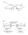
- FIG. 1 is a general structure diagram of a vehicle power feeding system to which a parking assist device for a vehicle according to an embodiment of the present invention is applied.
- FIG. 2 illustrates the principles of electric power transmission by resonance.
- FIG. 3 is a detailed structure diagram of the vehicle shown in FIG. 1 .
- FIG. 4 is a functional block diagram of a control device shown in FIG. 3 .
- FIG. 5 illustrates relation between the amount of positional deviation of a power reception unit with respect to a power transmission unit and a feeding voltage.
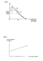
- FIG. 6 illustrates relation between the amount of positional deviation of the power reception unit with respect to the power transmission unit and a receiving voltage.
- FIG. 7 illustrates an example of relation between change in vehicle height of a vehicle and an output from a height sensor.
- FIG. 8 is a flowchart showing a procedure of parking assist control performed by the control device shown in FIG. 3 .
- FIG. 9 is a waveform diagram of main signals while the parking assist control for a vehicle is performed.
- FIG. 1 is a general structure diagram of a vehicle power feeding system to which a parking assist device for a vehicle according to an embodiment of the present invention is applied.
- a vehicle power feeding system 10 includes a vehicle 100 and a power feeding apparatus 200 .
- Vehicle 100 includes a power reception unit 110 , a camera 120 , a communication unit 130 , and a height sensor 135 .
- Power reception unit 110 is fixed to an underbody of vehicle 100 , and configured to receive electric power transmitted from a power transmission unit 220 (to be described later) of power feeding apparatus 200 in a non-contact manner.
- power reception unit 110 includes a self-resonant coil (to be described later), and receives electric power from power transmission unit 220 in a non-contact manner by resonating with a self-resonant coil included in power transmission unit 220 through an electromagnetic field.
- Camera 120 is provided to sense positional relation between vehicle 100 and power transmission unit 220 , and attached to a car body in such a manner that it can take an image behind the vehicle, for example.
- Communication unit 130 is a communication interface for conducting communication between vehicle 100 and power feeding apparatus 200 .
- Height sensor 135 is a sensor for sensing change in vehicle height of vehicle 100 .
- height sensor 135 is provided on a suspension of vehicle 100 , and senses change in vehicle height by measuring an amount of sinking of the vehicle with respect to a predetermined reference position as magnetic displacement or resistive displacement.
- a laser displacement gage provided on the underbody may be used to directly measure change in distance from a road surface.
- a variety of known devices can be used as height sensor 135 .
- Power feeding apparatus 200 includes a power supply device 210 , power transmission unit 220 , light emission units 230 , and a communication unit 240 .
- Power supply device 210 converts a commercial AC electric power supplied from a system power supply, for example, to a high-frequency electric power, and outputs the same to power transmission unit 220 .
- the high-frequency electric power generated by power supply device 210 has a frequency of 1 MHz to ten-plus MHz, for example.
- Power transmission unit 220 is fixed to a floor surface of a parking space, and configured to transmit the high-frequency electric power supplied from power supply device 210 to power reception unit 110 of vehicle 100 in a non-contact manner.
- power transmission unit 220 includes the self-resonant coil (to be described later), and transmits electric power to power reception unit 110 in a non-contact manner by resonating with the self-resonant coil included in power reception unit 110 through an electromagnetic field.
- the plurality of light emission units 230 are provided on power transmission unit 220 to indicate a position of power transmission unit 220 .
- Each of light emission units 230 is formed of an LED, for example.
- Communication unit 240 is a communication interface for conducting communication between power feeding apparatus 200 and vehicle 100 .
- power transmission unit 220 of power feeding apparatus 200 transmits a high-frequency electric power, and the self-resonant coil included in power reception unit 110 of vehicle 100 and the self-resonant coil included in power transmission unit 220 resonate with each other through an electromagnetic field, thereby feeding electric power from power feeding apparatus 200 to vehicle 100 .
- position adjustment between power reception unit 110 of vehicle 100 and power transmission unit 220 of power feeding apparatus 200 needs to be performed by guiding vehicle 100 to power feeding apparatus 200 .
- parking control of vehicle 100 to power feeding apparatus 200 is performed in two stages.
- steering of vehicle 100 is controlled based on an image taken by camera 120 , thus guiding vehicle 100 to power transmission unit 220 of power feeding apparatus 200 .
- an image of the plurality of light emission units 230 provided on power transmission unit 220 is taken by camera 120 , and positions and orientations of the plurality of light emission units 230 are recognized by image recognition.
- positions and orientations of power transmission unit 220 and vehicle 100 are recognized based on the image recognition result, and steering is controlled based on the recognition result, thus guiding vehicle 100 to power transmission unit 220 of power feeding apparatus 200 .
- the parking control is switched from the first stage to a second stage.
- electric power is fed from power transmission unit 220 to power reception unit 110 , and vehicle 100 is controlled in speed (decelerated/stopped) based on a power receiving situation of power reception unit 110 , thus performing position adjustment between power transmission unit 220 and power reception unit 110 .
- a distance between power transmission unit 220 and power reception unit 110 is estimated based on the power receiving situation of power reception unit 110 .
- vehicle 100 is controlled in speed (decelerated/stopped) based on the estimated result, thus performing position adjustment between power transmission unit 220 and power reception unit 110 .
- the selected map is used to estimate the amount of positional deviation of power reception unit 110 with respect to power transmission unit 220 based on the power receiving situation of power reception unit 110 , and position adjustment between power transmission unit 220 and power reception unit 110 is performed based on the estimated result.
- electric power transmitted from power transmission unit 220 in the second stage is set to be smaller than electric power supplied from power transmission unit 220 to power reception unit 110 after completion of the position adjustment between power transmission unit 220 and power reception unit 110 .
- the electric power transmission from power transmission unit 220 in the second stage is for the position adjustment between power transmission unit 220 and power reception unit 110 , and thus a large amount of electric power for substantial power feeding is unnecessary.
- FIG. 2 illustrates the principles of electric power transmission by resonance.
- two LC resonant coils having the same natural frequency resonate with each other in an electromagnetic field (near field) in the same way that two tuning forks resonate with each other, thus transmitting electric power from one of the coils to the other coil through the electromagnetic field.
- a high-frequency power supply 310 is connected to a primary coil 320 , and a high-frequency electric power of 1 MHz to ten-plus MHz is fed to a primary self-resonant coil 330 which is magnetically coupled to primary coil 320 by electromagnetic induction.
- Primary self-resonant coil 330 is an LC resonator having an inductance of the coil itself and a stray capacitance, and resonates with a secondary self-resonant coil 340 having a resonant frequency the same as that of primary self-resonant coil 330 through an electromagnetic field (near field). Consequently, energy (electric power) is moved from primary self-resonant coil 330 to secondary self-resonant coil 340 through the electromagnetic field.
- the energy (electric power) moved to secondary self-resonant coil 340 is taken by a secondary coil 350 which is magnetically coupled to secondary self-resonant coil 340 by electromagnetic induction, and supplied to a load 360 .
- Electric power transmission by resonance is implemented when a Q value indicating resonant strength of primary self-resonant coil 330 and secondary self-resonant coil 340 is greater than 100, for example.
- secondary self-resonant coil 340 and secondary coil 350 correspond to power reception unit 110 in FIG. 1
- primary coil 320 and primary self-resonant coil 330 correspond to power transmission unit 220 in FIG. 1 .
- FIG. 3 is a detailed structure diagram of vehicle 100 shown in FIG. 1 .
- vehicle 100 includes a power storage device 150 , a system main relay SMR 1 , a boost converter 162 , inverters 164 , 166 , motor generators 172 , 174 , an engine 176 , a power split device 177 , and a drive wheel 178 .
- Vehicle 100 also includes a secondary self-resonant coil 112 , a secondary coil 114 , a rectifier 140 , a DC/DC converter 142 , a system main relay SMR 2 , and a voltage sensor 190 .
- Vehicle 100 further includes a control device 180 , camera 120 , communication unit 130 , height sensor 135 , a touch display 182 , a parking assist switch (hereinafter also referred to as “PA switch”) 184 , and a power feeding request switch 186 .
- a control device 180 camera 120 , communication unit 130 , height sensor 135 , a touch display 182 , a parking assist switch (hereinafter also referred to as “PA switch”) 184 , and a power feeding request switch 186 .
- PA switch parking assist switch
- Vehicle 100 incorporates engine 176 and motor generator 174 as a driving source.
- Engine 176 and motor generators 172 , 174 are linked to power split device 177 .
- Vehicle 100 travels with a driving force generated by at least one of engine 176 and motor generator 174 .
- Mechanical power generated by engine 176 is split into two paths by power split device 177 . Namely, one is a path for transmitting the power to drive wheel 178 , and the other is a path for transmitting the power to motor generator 172 .
- Motor generator 172 is an AC rotating electric machine, and formed of a three-phase AC synchronous motor having a rotor in which a permanent magnet is buried, for example. Motor generator 172 generates electric power by using kinetic energy of engine 176 which was split by power split device 177 . When a state of charge (also referred to as “SOC,” and represented in percentage with respect to a fully charged state, for example) of power storage device 150 becomes lower than a predetermined value, for example, engine 176 is started and motor generator 172 generates electric power, to charge power storage device 150 .
- SOC state of charge
- motor generator 174 is also an AC rotating electric machine, and formed of a three-phase AC synchronous motor having a rotor in which a permanent magnet is buried, for example.
- Motor generator 174 generates a driving force by using at least one of the electric power stored in power storage device 150 and the electric power generated by motor generator 172 .
- the driving force from motor generator 174 is transmitted to drive wheel 178 .
- motor generator 174 operates as a power generator.
- motor generator 174 operates as a regenerative brake for converting traveling energy to electric power to generate a braking force.
- the electric power generated by motor generator 174 is stored in power storage device 150 .
- Power split device 177 is formed of a planetary gear including a sun gear, a pinion gear, a carrier, and a ring gear.
- the pinion gear engages with the sun gear and the ring gear.
- the carrier supports the pinion gear in a rotatable manner, and is linked to a crankshaft of engine 176 .
- the sun gear is linked to a rotation shaft of motor generator 172 .
- the ring gear is linked to a rotation shaft of motor generator 174 and drive wheel 178 .
- Power storage device 150 is a rechargeable DC power supply, and formed of a secondary battery such as a lithium-ion battery or a nickel-metal hydride battery, for example.
- Power storage device 150 stores electric power supplied from DC/DC converter 142 , and also stores regenerative electric power generated by motor generators 172 , 174 , Power storage device 150 supplies the stored electric power to boost converter 162 ,
- a capacitor having a large capacity, or any electric power buffer capable of temporarily storing electric power supplied from power feeding apparatus 200 ( FIG. 1 ) and regenerative electric power from motor generators 172 , 174 and supplying the stored electric power to boost converter 162 can be employed as power storage device 150 .
- System main relay SMR 1 is provided between power storage device 150 and boost converter 162 .
- System main relay SMR 1 electrically connects power storage device 150 to boost converter 162 when a signal SE 1 from control device 180 is activated, and cuts off an electrical path between power storage device 150 and boost converter 162 when signal SE 1 is deactivated.
- Boost converter 162 boosts, in response to a signal PWC from control device 180 , a voltage of a positive electrode line PL 2 to be equal to or higher than a voltage output from power storage device 150 , Boost converter 162 is formed of a DC chopper circuit, for example.
- Inverters 164 , 166 are provided correspondingly to motor generators 172 , 174 , respectively.
- Inverter 164 drives motor generator 172 in response to a signal PWI 1 from control device 180
- inverter 166 drives motor generator 174 in response to a signal PWI 2 from control device 180
- Inverters 164 , 166 are each formed of a three-phase bridge circuit, for example.
- Secondary self-resonant coil 112 is an LC resonant coil with open (unconnected) opposing ends, and receives electric power from power feeding apparatus 200 by resonating with a primary self-resonant coil (to be described later) of power feeding apparatus 200 through an electromagnetic field.
- a capacity component of secondary self-resonant coil 112 is a stray capacitance of the coil, however, a capacitor connected across both ends of the coil may be provided, Turns of secondary self-resonant coil 112 are set as appropriate to have a large Q value (e.g., Q>100) indicating resonant strength of the primary self-resonant coil of power feeding apparatus 200 and secondary self-resonant coil 112 , large ⁇ indicating a degree of coupling thereof and the like, based on a distance from the primary self-resonant coil, a resonant frequency of the primary self-resonant coil and secondary self-resonant coil 112 , and the like.
- Q value e.g., Q>100
- Secondary coil 114 is provided coaxially with secondary self-resonant coil 112 , and can be magnetically coupled to secondary self-resonant coil 112 by electromagnetic induction. Secondary coil 114 takes electric power received by secondary self-resonant coil 112 by electromagnetic induction, and outputs the same to rectifier 140 . Secondary self-resonant coil 112 and secondary coil 114 form power reception unit 110 shown in FIG. 1 .
- Rectifier 140 rectifies the AC electric power taken by secondary coil 114 .
- DC/DC converter 142 converts the electric power rectified by rectifier 140 to electric power having a voltage level of power storage device 150 in response to a signal PWD from control device 180 , and outputs the same to power storage device 150 .
- System main relay SMR 2 is provided between DC/DC converter 142 and power storage device 150 .
- System main relay SMR 2 electrically connects power storage device 150 to DC/DC converter 142 when a signal SE 2 from control device 180 is activated, and cuts off an electrical path between power storage device 150 and DC/DC converter 142 when signal SE 2 is deactivated.
- Voltage sensor 190 detects a voltage VH between rectifier 140 and DC/DC converter 142 , and outputs the detected value to control device 180 .
- touch display 182 While control of guiding and parking vehicle 100 to a desired parking position (hereinafter also referred to as “parking assist control”) is performed, touch display 182 receives information about an image which has been taken by camera 120 from control device 180 , and displays the received image information. In addition to displaying the image information, touch display 182 receives input from a user for determining a parking position for vehicle 100 , and outputs information about the input parking position to control device 180 .
- a display of a car navigation device can be used as touch display 182 , for example.
- Control device 180 generates signals PWC, PWI 1 , PWI 2 for driving boost converter 162 and motor generators 172 , 174 , respectively, based on an accelerator position, a vehicle speed, and other signals from various sensors, and outputs generated signals PWC, PWI 1 , PWI 2 to boost converter 162 and inverters 164 , 166 , respectively.
- control device 180 activates signal SE 1 to turn system main relay SMR 1 on, and deactivates signal SE 2 to turn system main relay SMR 2 off.
- control device 180 When PA switch 184 and power feeding request switch 186 are turned on by the user, control device 180 receives information about an image which has been taken by camera 120 from camera 120 , and outputs the received image information to touch display 182 . Control device 180 also receives information about a parking position which has been input by the user through touch display 182 from touch display 182 . Further, control device 180 receives a detected value for voltage VH which has been detected by voltage sensor 190 from voltage sensor 190 . Then, based on these pieces of data, control device 180 performs the parking assist control in a manner described later to guide vehicle 100 to power transmission unit 220 of power feeding apparatus 200 ( FIG. 1 ).
- control device 180 transmits a power feeding instruction to power feeding apparatus 200 via communication unit 130 , and activates signal SE 2 to turn system main relay SMR 2 on. Further, control device 180 generates signal PWD for driving DC/DC converter 142 , and outputs generated signal PWD to DC/DC converter 142 . As a result, power feeding apparatus 200 starts charging power storage device 150 .
- PA switch 184 is a switch for the user to request parking assist with camera 120 and touch display 182 .
- Power feeding request switch 186 is a switch for the user to request charging of power storage device 150 by power feeding apparatus 200 .
- FIG. 4 is a functional block diagram of control device 180 shown in FIG. 3 .
- control device 180 includes a parking assist ECU (Electronic Control Unit) 410 , a steering ECU 420 , a vehicle ECU 430 , a motor control ECU 440 , and a charging ECU 450 .
- ECU Electronic Control Unit
- parking assist ECU 410 When not-shown PA switch 184 and power feeding request switch 186 are turned on, parking assist ECU 410 performs control for guiding vehicle 100 to power transmission unit 220 of power feeding apparatus 200 ( FIG. 1 ) based on the image information received from camera 120 .
- parking assist ECU 410 outputs the image information received from camera 120 to touch display 182 , and recognizes power transmission unit 220 based on the image information.
- the plurality of light emission units 230 indicating a position and orientation of power transmission unit 220 are provided on power transmission unit 220 .
- parking assist ECU 410 recognizes positional relation with power transmission unit 220 (general distance and orientation) based on the image of the plurality of light emission units 230 shown on camera 120 .
- Parking assist ECU 410 receives an output from height sensor 135 , and corrects the positional relation based on the output from height sensor 135 .
- parking assist ECU 410 receives the information about the parking position which has been input by the user through touch display 182 from touch display 182 . Then, based on the recognition result of power transmission unit 220 and the parking position information received from touch display 182 , parking assist ECU 410 outputs a backing instruction to vehicle ECU 430 such that vehicle 100 will back up at a predetermined speed VS 1 , and outputs a steering instruction to steering ECU 420 such that vehicle 100 will be guided in an appropriate orientation to power transmission unit 220 .
- parking assist ECU 410 When the steering control is completed (i.e., a state where steering is no longer operated and the vehicle is only required to back up), and vehicle 100 has been guided to the predetermined position, parking assist ECU 410 notifies vehicle ECU 430 of the situation.
- the predetermined position may be a position where power transmission unit 220 falls outside of an image taking range of camera 120 by a predetermined amount due to approach of vehicle 100 to power transmission unit 220 .
- Steering ECU 420 actually performs automatic steering control based on the steering instruction received from parking assist ECU 410 .
- vehicle ECU 430 During normal travel, vehicle ECU 430 outputs a control instruction to motor control ECU 440 in accordance with an operation situation of an accelerator pedal/brake pedal, a traveling situation of the vehicle and the like.
- vehicle ECU 430 During the parking assist control, vehicle ECU 430 generates, in response to the backing instruction from parking assist ECU 410 , a signal for driving motor generator 174 ( FIG. 3 ) such that the vehicle will back up at speed VS 1 , and outputs the same to motor control ECU 440 .
- vehicle ECU 430 controls (decelerates/stops) vehicle 100 in speed based on a power receiving situation of power reception unit 110 . As a result, position adjustment between power transmission unit 220 and power reception unit 110 is performed.
- vehicle ECU 430 generates a signal for causing the vehicle to back up at a speed VS 2 lower than speed VS 1 , and outputs the same to motor control ECU 440 . Further, vehicle ECU 430 transmits a power feeding instruction which requests electric power transmission for position adjustment to power feeding apparatus 200 via communication unit 130 , and receives a detected value for voltage VH ( FIG. 3 ) indicating the receiving voltage from power feeding apparatus 200 from charging ECU 450 . Then, vehicle ECU 430 estimates the amount of positional deviation (amount of lateral deviation in the direction horizontal to the road surface) between power transmission unit 220 and power reception unit 110 based on the detected value for voltage VH.
- voltage VH indicating the receiving voltage varies with a distance between power transmission unit 220 and power reception unit 110 .
- FIG. 6 illustrates relation between the amount of positional deviation of power reception unit 110 with respect to power transmission unit 220 and the receiving voltage.
- the amount of positional deviation is 0 when power reception unit 110 faces power transmission unit 220 .
- the output voltage from power feeding apparatus 200 is constant.
- curves M 1 to M 3 illustrate relation among different vehicle heights of vehicle 100 , with the vehicle height becoming shorter in the order of curves M 1 , M 2 , M 3 .
- the relation between the amount of positional deviation of power reception unit 110 with respect to power transmission unit 220 and the receiving voltage changes.
- FIG. 7 illustrates an example of relation between change in vehicle height of vehicle 100 and an output from height sensor 135 .
- the output from height sensor 135 changes.
- a plurality of maps each indicating relation between an amount of positional deviation of power reception unit 110 with respect to power transmission unit 220 and voltage VH (receiving voltage) are prepared in advance according to outputs from height sensor 135 . Then, one of the maps is selected based on an output from height sensor 135 , and the selected map is used to estimate the amount of positional deviation of power reception unit 110 with respect to power transmission unit 220 based on voltage VH.
- VH exceeds a value Vth of voltage VH which corresponds to a predetermined allowable value Lth of the amount of positional deviation
- vehicle ECU 430 outputs an instruction indicating deceleration or stop of vehicle 100 to motor control ECU 440 , based on the estimated result of the distance between power transmission unit 220 and power reception unit 110 .
- vehicle ECU 430 transmits a power feeding instruction for charging power storage device 150 to power feeding apparatus 200 via communication unit 130 , and outputs an instruction indicating start of charging of power storage device 150 to charging ECU 450 .
- Motor control ECU 440 controls motor generators 172 , 174 and boost converter 162 based on the instruction from vehicle ECU 430 . Specifically, motor control ECU 440 generates signals for driving motor generators 172 , 174 and boost converter 162 , and outputs the same to inverters 164 , 166 and boost converter 162 , respectively.
- Charging ECU 450 receives the detected value for voltage VH indicating the receiving voltage from power feeding apparatus 200 from voltage sensor 190 ( FIG. 3 ), and outputs the received value to vehicle ECU 430 . Further, in response to the charging start instruction from vehicle ECU 430 , charging ECU 450 activates signal SE 2 output to system main relay SMR 2 to turn system main relay SMR 2 on. Then, charging ECU 450 generates a signal for driving DC/DC converter 142 , and outputs the same to DC/DC converter 142 . As a result, charging of power storage device 150 is performed.
- parking assist ECU 410 and steering ECU 420 constitute a guidance control unit 460 .
- Guidance control unit 460 controls steering of vehicle 100 based on the image taken by camera 120 , thus guiding vehicle 100 to power transmission unit 220 of power feeding apparatus 200 (steering mode).
- vehicle ECU 430 , motor control ECU 440 and charging ECU 450 constitute a vehicle control unit 470 .
- Vehicle control unit 470 estimates the amount of positional deviation of power reception unit 110 with respect to power transmission unit 220 based on the power receiving situation (voltage VH) of power reception unit 110 . Then, vehicle control unit 470 controls (decelerates/stops) vehicle 100 in speed based on the estimated result, thus performing position adjustment between power transmission unit 220 and power reception unit 110 (deceleration/stop mode).
- the amount of positional deviation between power transmission unit 220 and power reception unit 110 is estimated using the map indicating the relation between the receiving voltage (voltage VH) of power reception unit 110 and the distance between power transmission unit 220 and power reception unit 110 . Since the receiving voltage (voltage VH) depends on the distance between power transmission unit 220 and power reception unit 110 , in this embodiment, the plurality of maps are prepared in advance according to outputs from height sensor 135 which senses change in vehicle height of vehicle 100 . Then, one of the maps is selected based on an output from height sensor 135 , and the selected map is used to estimate the amount of positional deviation between power transmission unit 220 and power reception unit 110 based on voltage VH.
- efficiency of electric power transmission from power transmission unit 220 to power reception unit 110 may be used as an index of the power receiving situation.
- FIG. 8 is a flowchart showing a procedure of the parking assist control performed by control device 180 shown in FIG. 3 .
- control device 180 determines whether or not PA switch 184 and power feeding request switch 186 have been turned on by the user (step S 10 ). If it is determined that these switches have not been turned on (NO at step S 10 ), control device 180 proceeds to step S 120 without performing a subsequent series of steps.
- control device 180 determines whether or not a parking position for vehicle 100 has been determined by the user on a screen of touch display 182 (step S 20 ).
- control device 180 performs automatic steering operation by guidance control unit 460 including parking assist ECU 410 and steering ECU 420 based on the image information from camera 120 (step S 30 ).
- control device 180 determines whether or not vehicle 100 has been guided to the predetermined position with respect to power transmission unit 220 of power feeding apparatus 200 (step S 40 ), For example, when power transmission unit 220 shown on touch display 182 falls outside of the image taking range by the predetermined amount, it is determined that the vehicle has been guided to the predetermined position.
- control mode is switched from the steering mode to the deceleration/stop mode. Then, control device 180 starts the speed control (deceleration/stop) by vehicle control unit 470 including vehicle ECU 430 , motor control ECU 440 and charging ECU 450 , based on the receiving voltage (voltage VH) of power reception unit 110 from power feeding apparatus 200 (step S 50 ).
- control device 180 generates a deceleration instruction, and decelerates vehicle 100 from speed VS 1 during the automatic steering operation to lower speed VS 2 (step S 60 ).
- control device 180 obtains an output from height sensor 135 (step S 70 ).
- control device 180 selects one of the plurality of maps which are prepared in advance, each indicating relation between voltage VH and an amount of positional deviation of power reception unit 110 with respect to power transmission unit 220 , based on the output from height sensor 135 which was obtained at step S 70 (step S 80 ).
- control device 180 uses the selected map to determine whether or not a value of voltage VH indicating the receiving voltage has exceeded predetermined threshold value Vth ( FIG. 6 ) (step S 90 ). If it is determined that the value of voltage VH has exceeded threshold value Vth (YES at step S 90 ), control device 180 generates a stop instruction, and causes vehicle 100 to stop (step S 100 ).
- control device 180 transmits a power feeding instruction to power feeding apparatus 200 , and causes power feeding apparatus 200 to start charging power storage device 150 (step S 110 ).
- FIG. 9 is a waveform diagram of main signals while the parking assist control for vehicle 100 is performed.
- guidance control unit 460 FIG. 3 .
- a backing speed of vehicle 100 in the steering mode is set to VS 1 .
- the control mode is switched from the steering mode to the deceleration/stop mode, and vehicle control unit 470 ( FIG. 3 ) performs the speed control of vehicle 100 .
- the backing speed of vehicle 100 is decelerated to VS 2 lower than VS 1 .
- the relation between the power receiving situation of power reception unit 110 and the amount of positional deviation of power reception unit 110 with respect to power transmission unit 220 which is predetermined according to the output from height sensor 135 which senses change in vehicle height of vehicle 100 , is used to perform position adjustment between power transmission unit 220 and power reception unit 110 based on the output from height sensor 135 and the power receiving situation. Accordingly, even if the vehicle height changes with change in the number of passengers or in the weight of luggage, accuracy of the position adjustment between power transmission unit 220 and power reception unit 110 is maintained. According to this embodiment, therefore, parking accuracy of vehicle 100 with respect to power feeding apparatus 200 is improved.
- camera 120 is installed on the rear of the vehicle on the assumption of reverse parking of vehicle 100 with respect to power feeding apparatus 200 in the above embodiment, camera 120 may be installed on the forward of the vehicle for forward parking of vehicle 100 with respect to power feeding apparatus 200 .
- a method of transmitting electric power from power feeding apparatus 200 to vehicle 100 is not necessarily limited to resonance, but may be other non-contact electric power transmission methods such as electric power transmission using electromagnetic induction, or electric power transmission using a microwave. Also in these electric power transmission methods, a distance between power transmission unit 220 and power reception unit 110 can be estimated based on a situation of power feeding from power feeding apparatus 200 to vehicle 100 .
- the position and orientation of power transmission unit 220 are recognized by image recognition based on light emission units 230 in the above description, the shape and the like of power transmission unit 220 may be recognized by image recognition without providing light emission units 230 . By providing light emission units 230 as in the above embodiment, the position and orientation of power transmission unit 220 can be recognized even at night.
- the present invention is also applicable to other types of hybrid cars. That is, the present invention is also applicable, for example, to a so-called series hybrid car which uses engine 176 only for driving motor generator 172 and generates a driving force of the car only by motor generator 174 , a hybrid car in which only regenerative energy out of kinetic energy generated by engine 176 is recovered as electric energy, a motor-assisted hybrid car in which an engine is used for main mechanical power and a motor assists the engine as necessary, and the like.
- the present invention is also applicable to an electric vehicle not including engine 176 but traveling only with electric power, and a fuel cell car including a fuel cell in addition to power storage device 150 as a DC electric power supply.
- the present invention is also applicable to a vehicle not including boost converter 162 , and a vehicle not including DC/DC converter 142 .
Landscapes
- Engineering & Computer Science (AREA)
- Transportation (AREA)
- Mechanical Engineering (AREA)
- Power Engineering (AREA)
- Computer Networks & Wireless Communication (AREA)
- Chemical & Material Sciences (AREA)
- Combustion & Propulsion (AREA)
- Electric Propulsion And Braking For Vehicles (AREA)
- Charge And Discharge Circuits For Batteries Or The Like (AREA)
- Current-Collector Devices For Electrically Propelled Vehicles (AREA)
Applications Claiming Priority (1)
| Application Number | Priority Date | Filing Date | Title |
|---|---|---|---|
| PCT/JP2010/057048 WO2011132272A1 (ja) | 2010-04-21 | 2010-04-21 | 車両の駐車支援装置およびそれを備える電動車両 |
Publications (2)
| Publication Number | Publication Date |
|---|---|
| US20130030615A1 US20130030615A1 (en) | 2013-01-31 |
| US8655530B2 true US8655530B2 (en) | 2014-02-18 |
Family
ID=44833831
Family Applications (1)
| Application Number | Title | Priority Date | Filing Date |
|---|---|---|---|
| US13/142,429 Active US8655530B2 (en) | 2010-04-21 | 2010-04-21 | Parking assist device for vehicle and electrically powered vehicle including the same |
Country Status (4)
| Country | Link |
|---|---|
| US (1) | US8655530B2 (ja) |
| JP (1) | JP4868093B2 (ja) |
| CN (1) | CN102300744B (ja) |
| WO (1) | WO2011132272A1 (ja) |
Cited By (2)
| Publication number | Priority date | Publication date | Assignee | Title |
|---|---|---|---|---|
| US20150217655A1 (en) * | 2014-02-04 | 2015-08-06 | Ford Global Technologies, Llc | Vertical wireless power transfer system for charging electric vehicles |
| US20180287434A1 (en) * | 2017-03-28 | 2018-10-04 | Tdk Corporation | Wireless power receiver and wireless power transmission system |
Families Citing this family (33)
| Publication number | Priority date | Publication date | Assignee | Title |
|---|---|---|---|---|
| JP5974460B2 (ja) * | 2011-11-25 | 2016-08-23 | 株式会社Ihi | 移動車両及び非接触電力伝送装置 |
| JP5966407B2 (ja) * | 2012-02-15 | 2016-08-10 | 株式会社Ihi | 移動車両及び非接触電力伝送装置 |
| JP2013169109A (ja) * | 2012-02-16 | 2013-08-29 | Ihi Corp | 移動車両及び非接触電力伝送装置 |
| JP6044124B2 (ja) * | 2012-06-11 | 2016-12-14 | 株式会社Ihi | 移動車両及び非接触電力伝送装置 |
| JP5923724B2 (ja) * | 2011-12-06 | 2016-05-25 | パナソニックIpマネジメント株式会社 | 車輌案内装置 |
| JP5859864B2 (ja) * | 2012-02-03 | 2016-02-16 | 矢崎総業株式会社 | 非接触電力伝送システム |
| GB2500691B (en) * | 2012-03-30 | 2016-06-15 | Jaguar Land Rover Ltd | Charging system for a vehicle |
| CN103619625A (zh) * | 2012-03-30 | 2014-03-05 | 本田技研工业株式会社 | 内燃机控制设备和内燃机控制方法 |
| JP2013236524A (ja) * | 2012-05-11 | 2013-11-21 | Mitsubishi Electric Corp | 非接触給電システム |
| US8700258B2 (en) | 2012-09-12 | 2014-04-15 | GM Global Technology Operations LLC | Park assist system |
| JP5643270B2 (ja) | 2012-09-13 | 2014-12-17 | トヨタ自動車株式会社 | 車両および非接触給電システム |
| CN104620470B (zh) * | 2012-09-13 | 2017-08-11 | 丰田自动车株式会社 | 非接触供电系统以及在该系统中使用的送电装置和车辆 |
| JP6043462B2 (ja) * | 2012-09-27 | 2016-12-14 | Ihi運搬機械株式会社 | 車両給電装置 |
| CN103847536B (zh) * | 2012-11-30 | 2016-06-01 | 英业达科技有限公司 | 电动车辆充电监控的车用装置及其方法 |
| DE112013006857T5 (de) * | 2013-03-22 | 2015-12-03 | Toyota Jidosha Kabushiki Kaisha | Fahrzeug und kontaktloses Leistungsversorgungssystem |
| JP6123134B2 (ja) * | 2013-03-28 | 2017-05-10 | パナソニックIpマネジメント株式会社 | 給電制御装置 |
| WO2014181669A1 (ja) | 2013-05-10 | 2014-11-13 | 株式会社Ihi | 非接触給電システム |
| DE102013016702A1 (de) | 2013-10-08 | 2015-04-09 | Audi Ag | Crasherkennung bei stillstehendem Kraftfahrzeug |
| JP6115453B2 (ja) * | 2013-11-27 | 2017-04-19 | トヨタ自動車株式会社 | 非接触電力伝送システム、および車両 |
| JP2015116023A (ja) * | 2013-12-11 | 2015-06-22 | 三菱電機株式会社 | 非接触給電システム及び受電装置 |
| DE102014003937B4 (de) | 2014-03-19 | 2022-06-15 | Audi Ag | Verfahren zur bidirektionalen Kommunikation zwischen einem Kraftfahrzeug und einer Infrastruktureinrichtung und Kraftfahrzeug |
| DE102014215299A1 (de) * | 2014-08-04 | 2016-02-04 | Robert Bosch Gmbh | Verfahren zum berührungslosen Laden oder Entladen eines batteriebetriebenen Objekts |
| WO2016068135A1 (ja) | 2014-10-28 | 2016-05-06 | 株式会社Ihi | 送電装置、送電方法及び非接触給電システム |
| WO2016121044A1 (ja) * | 2015-01-29 | 2016-08-04 | 日産自動車株式会社 | 駐車支援システム及び駐車支援方法 |
| JP6464994B2 (ja) * | 2015-11-09 | 2019-02-06 | 株式会社デンソー | 非接触電力伝送装置 |
| US9815342B2 (en) * | 2015-11-20 | 2017-11-14 | Ford Global Technologies, Llc | Vehicle positioning to charge TPMS batteries |
| JP6390600B2 (ja) * | 2015-12-02 | 2018-09-19 | トヨタ自動車株式会社 | 車両 |
| DE102017130173A1 (de) * | 2017-02-24 | 2018-08-30 | Denso Ten Limited | Ladeunterstützungsvorrichtung |
| JP6458084B2 (ja) * | 2017-05-24 | 2019-01-23 | 本田技研工業株式会社 | 非接触電力伝送システム |
| JP6774379B2 (ja) * | 2017-05-24 | 2020-10-21 | 本田技研工業株式会社 | 非接触電力伝送システム |
| JP2020010491A (ja) * | 2018-07-06 | 2020-01-16 | トヨタ自動車株式会社 | 非接触電力伝送システム |
| JP7070262B2 (ja) * | 2018-09-12 | 2022-05-18 | トヨタ自動車株式会社 | 非接触電力伝送システム |
| WO2022201728A1 (ja) * | 2021-03-22 | 2022-09-29 | パナソニックIpマネジメント株式会社 | 自動バレー駐車方法及び自動バレー駐車システム |
Citations (25)
| Publication number | Priority date | Publication date | Assignee | Title |
|---|---|---|---|---|
| JPH04208032A (ja) | 1990-11-30 | 1992-07-29 | Hitachi Kiden Kogyo Ltd | 磁気浮上式ビークルの位置決め兼用充電装置の制御方法 |
| JPH09213378A (ja) | 1996-01-30 | 1997-08-15 | Sumitomo Wiring Syst Ltd | 電気自動車用充電システム |
| US5821731A (en) | 1996-01-30 | 1998-10-13 | Sumitomo Wiring Systems, Ltd. | Connection system and connection method for an electric automotive vehicle |
| JPH11208496A (ja) * | 1998-01-26 | 1999-08-03 | Honda Motor Co Ltd | 車両の自動操舵装置 |
| JP2003182489A (ja) | 2001-12-19 | 2003-07-03 | Matsushita Electric Ind Co Ltd | 駐車支援装置 |
| US20030122687A1 (en) | 2001-12-27 | 2003-07-03 | Philips Electronics North America Corportion | Computer vision based parking assistant |
| US20030205869A1 (en) * | 2000-05-25 | 2003-11-06 | Randy Schutt | Height control system and sensor therefor |
| JP2004291865A (ja) | 2003-03-27 | 2004-10-21 | Toyota Motor Corp | 駐車支援装置 |
| JP2006288034A (ja) | 2005-03-31 | 2006-10-19 | Matsushita Electric Ind Co Ltd | 送受電装置 |
| WO2007008646A2 (en) | 2005-07-12 | 2007-01-18 | Massachusetts Institute Of Technology | Wireless non-radiative energy transfer |
| US7192032B2 (en) * | 2002-04-23 | 2007-03-20 | Barksdale, Inc. | Electronic control of vehicle air suspension |
| US7192033B2 (en) * | 2001-05-25 | 2007-03-20 | Haldex Brake Corporation | Trailing arm suspension and height control system with motorized valve therefor |
| JP2007097345A (ja) | 2005-09-29 | 2007-04-12 | Toyota Motor Corp | 駐車支援装置および車両と地上機器との間の電力授受方法 |
| WO2008118178A1 (en) | 2007-03-27 | 2008-10-02 | Massachusetts Institute Of Technology | Wireless energy transfer |
| US20080278264A1 (en) | 2005-07-12 | 2008-11-13 | Aristeidis Karalis | Wireless energy transfer |
| CN101632216A (zh) | 2006-08-16 | 2010-01-20 | 弗莱克斯电子有限责任公司 | 功率变换器中的箝位二极管复位和开关式电源中的断电检测 |
| US20100049414A1 (en) * | 2008-08-22 | 2010-02-25 | Fuji Jukogyo Kabushiki Kaisha | Control apparatus for electric vehicle |
| US20100201204A1 (en) * | 2009-02-09 | 2010-08-12 | Kabushiki Kaisha Toyota Jidoshokki | Non-contact power transmission apparatus |
| US7806417B1 (en) * | 2008-09-08 | 2010-10-05 | Hwh Corporation | Height averaging means for use with a motor vehicle suspension control system |
| US7894956B2 (en) * | 2005-03-22 | 2011-02-22 | Honda Motor Co., Ltd. | Steering control device for vehicles |
| US20110057813A1 (en) * | 2009-09-04 | 2011-03-10 | Salvador Toledo | Vehicle Park Assist System and Method for Parking a Vehicle Using Such System |
| US20110082612A1 (en) | 2008-11-07 | 2011-04-07 | Toyota Jidosha Kabushiki Kaisha | Power feeding system for vehicle, electrically powered vehicle and power feeding apparatus for vehicle |
| US8041472B2 (en) * | 2006-07-25 | 2011-10-18 | Toyota Jidosha Kabushiki Kaisha | Positioning device, and navigation system |
| JP2011209251A (ja) * | 2010-03-31 | 2011-10-20 | Mazda Motor Corp | 車高検出装置 |
| US8126625B2 (en) * | 2007-02-20 | 2012-02-28 | Toyota Jidosha Kabushiki Kaisha | Vehicle drive assist apparatus and method |
Family Cites Families (3)
| Publication number | Priority date | Publication date | Assignee | Title |
|---|---|---|---|---|
| JP5238420B2 (ja) * | 2008-09-11 | 2013-07-17 | 矢崎総業株式会社 | 車両用ワイヤレス充電システム |
| CN102165669B (zh) * | 2008-09-25 | 2013-03-20 | 丰田自动车株式会社 | 供电系统和电动车辆 |
| CN101673962A (zh) * | 2009-10-14 | 2010-03-17 | 奇瑞汽车股份有限公司 | 电动汽车无线充电系统 |
-
2010
- 2010-04-21 WO PCT/JP2010/057048 patent/WO2011132272A1/ja active Application Filing
- 2010-04-21 CN CN2010800038704A patent/CN102300744B/zh not_active Expired - Fee Related
- 2010-04-21 US US13/142,429 patent/US8655530B2/en active Active
- 2010-04-21 JP JP2011523631A patent/JP4868093B2/ja not_active Expired - Fee Related
Patent Citations (79)
| Publication number | Priority date | Publication date | Assignee | Title |
|---|---|---|---|---|
| JPH04208032A (ja) | 1990-11-30 | 1992-07-29 | Hitachi Kiden Kogyo Ltd | 磁気浮上式ビークルの位置決め兼用充電装置の制御方法 |
| JPH09213378A (ja) | 1996-01-30 | 1997-08-15 | Sumitomo Wiring Syst Ltd | 電気自動車用充電システム |
| US5821731A (en) | 1996-01-30 | 1998-10-13 | Sumitomo Wiring Systems, Ltd. | Connection system and connection method for an electric automotive vehicle |
| JPH11208496A (ja) * | 1998-01-26 | 1999-08-03 | Honda Motor Co Ltd | 車両の自動操舵装置 |
| US6991239B2 (en) * | 2000-05-25 | 2006-01-31 | Haldex Brake Corporation | Height control system and sensor therefor |
| US20030205869A1 (en) * | 2000-05-25 | 2003-11-06 | Randy Schutt | Height control system and sensor therefor |
| US7306239B2 (en) * | 2000-05-25 | 2007-12-11 | Haldex Brake Corporation | Height control system and sensor therefor |
| US7192033B2 (en) * | 2001-05-25 | 2007-03-20 | Haldex Brake Corporation | Trailing arm suspension and height control system with motorized valve therefor |
| JP2003182489A (ja) | 2001-12-19 | 2003-07-03 | Matsushita Electric Ind Co Ltd | 駐車支援装置 |
| JP2005512893A (ja) | 2001-12-27 | 2005-05-12 | コーニンクレッカ フィリップス エレクトロニクス エヌ ヴィ | コンピュータビジョンに基づく駐車支援 |
| US20030122687A1 (en) | 2001-12-27 | 2003-07-03 | Philips Electronics North America Corportion | Computer vision based parking assistant |
| US7192032B2 (en) * | 2002-04-23 | 2007-03-20 | Barksdale, Inc. | Electronic control of vehicle air suspension |
| US7155325B2 (en) | 2003-03-27 | 2006-12-26 | Aisin Seiki Kabushiki Kaisha | Parking assist apparatus |
| JP2004291865A (ja) | 2003-03-27 | 2004-10-21 | Toyota Motor Corp | 駐車支援装置 |
| US7894956B2 (en) * | 2005-03-22 | 2011-02-22 | Honda Motor Co., Ltd. | Steering control device for vehicles |
| JP2006288034A (ja) | 2005-03-31 | 2006-10-19 | Matsushita Electric Ind Co Ltd | 送受電装置 |
| US20100171370A1 (en) | 2005-07-12 | 2010-07-08 | Aristeidis Karalis | Maximizing power yield from wireless power magnetic resonators |
| US20100123354A1 (en) | 2005-07-12 | 2010-05-20 | Joannopoulos John D | Wireless energy transfer with high-q devices at variable distances |
| WO2007008646A2 (en) | 2005-07-12 | 2007-01-18 | Massachusetts Institute Of Technology | Wireless non-radiative energy transfer |
| EP1902505A2 (en) | 2005-07-12 | 2008-03-26 | Massachusetts Institute of Technology (MIT) | Wireless non-radiative energy transfer |
| KR20080031398A (ko) | 2005-07-12 | 2008-04-08 | 메사추세츠 인스티튜트 오브 테크놀로지 | 무선 비-방사성 에너지 전달 |
| CN101258658A (zh) | 2005-07-12 | 2008-09-03 | 麻省理工学院 | 无线非辐射能量传递 |
| US20100264745A1 (en) | 2005-07-12 | 2010-10-21 | Aristeidis Karalis | Resonators for wireless power applications |
| CN101860089A (zh) | 2005-07-12 | 2010-10-13 | 麻省理工学院 | 无线非辐射能量传递 |
| US20100253152A1 (en) | 2005-07-12 | 2010-10-07 | Aristeidis Karalis | Long range low frequency resonator |
| US20100237706A1 (en) | 2005-07-12 | 2010-09-23 | Aristeidis Karalis | Wireless power system and proximity effects |
| US20080278264A1 (en) | 2005-07-12 | 2008-11-13 | Aristeidis Karalis | Wireless energy transfer |
| JP2009501510A (ja) | 2005-07-12 | 2009-01-15 | マサチューセッツ インスティテュート オブ テクノロジー | 無線非放射型エネルギー転送 |
| US20100237707A1 (en) | 2005-07-12 | 2010-09-23 | Aristeidis Karalis | Increasing the q factor of a resonator |
| US20090195332A1 (en) | 2005-07-12 | 2009-08-06 | John D Joannopoulos | Wireless non-radiative energy transfer |
| US20090195333A1 (en) | 2005-07-12 | 2009-08-06 | John D Joannopoulos | Wireless non-radiative energy transfer |
| US20090224856A1 (en) | 2005-07-12 | 2009-09-10 | Aristeidis Karalis | Wireless energy transfer |
| AU2006269374B2 (en) | 2005-07-12 | 2009-10-08 | Massachusetts Institute Of Technology | Wireless non-radiative energy transfer |
| US20090267710A1 (en) | 2005-07-12 | 2009-10-29 | Joannopoulos John D | Wireless non-radiative energy transfer |
| US20090267709A1 (en) | 2005-07-12 | 2009-10-29 | Joannopoulos John D | Wireless non-radiative energy transfer |
| US20100237708A1 (en) | 2005-07-12 | 2010-09-23 | Aristeidis Karalis | Transmitters and receivers for wireless energy transfer |
| US20100231053A1 (en) | 2005-07-12 | 2010-09-16 | Aristeidis Karalis | Wireless power range increase using parasitic resonators |
| AU2010200044A1 (en) | 2005-07-12 | 2010-01-28 | Massachusetts Institute Of Technology | Wireless non-radiative energy transfer |
| US20100225175A1 (en) | 2005-07-12 | 2010-09-09 | Aristeidis Karalis | Wireless power bridge |
| US20100207458A1 (en) | 2005-07-12 | 2010-08-19 | Joannopoulos John D | Wireless energy transfer over a distance with devices at variable distances |
| AU2006269374C1 (en) | 2005-07-12 | 2010-03-25 | Massachusetts Institute Of Technology | Wireless non-radiative energy transfer |
| US20100096934A1 (en) | 2005-07-12 | 2010-04-22 | Joannopoulos John D | Wireless energy transfer with high-q similar resonant frequency resonators |
| US20100102640A1 (en) | 2005-07-12 | 2010-04-29 | Joannopoulos John D | Wireless energy transfer to a moving device between high-q resonators |
| US20100102641A1 (en) | 2005-07-12 | 2010-04-29 | Joannopoulos John D | Wireless energy transfer across variable distances |
| US20100102639A1 (en) | 2005-07-12 | 2010-04-29 | Joannopoulos John D | Wireless non-radiative energy transfer |
| US20100117456A1 (en) | 2005-07-12 | 2010-05-13 | Aristeidis Karalis | Applications of wireless energy transfer using coupled antennas |
| US20100117455A1 (en) | 2005-07-12 | 2010-05-13 | Joannopoulos John D | Wireless energy transfer using coupled resonators |
| US20070222542A1 (en) | 2005-07-12 | 2007-09-27 | Joannopoulos John D | Wireless non-radiative energy transfer |
| US20100123353A1 (en) | 2005-07-12 | 2010-05-20 | Joannopoulos John D | Wireless energy transfer with high-q from more than one source |
| US20100123355A1 (en) | 2005-07-12 | 2010-05-20 | Joannopoulos John D | Wireless energy transfer with high-q sub-wavelength resonators |
| US20100127573A1 (en) | 2005-07-12 | 2010-05-27 | Joannopoulos John D | Wireless energy transfer over a distance at high efficiency |
| US20100127574A1 (en) | 2005-07-12 | 2010-05-27 | Joannopoulos John D | Wireless energy transfer with high-q at high efficiency |
| US20100127575A1 (en) | 2005-07-12 | 2010-05-27 | Joannopoulos John D | Wireless energy transfer with high-q to more than one device |
| US20100133918A1 (en) | 2005-07-12 | 2010-06-03 | Joannopoulos John D | Wireless energy transfer over variable distances between resonators of substantially similar resonant frequencies |
| US20100133920A1 (en) | 2005-07-12 | 2010-06-03 | Joannopoulos John D | Wireless energy transfer across a distance to a moving device |
| US20100133919A1 (en) | 2005-07-12 | 2010-06-03 | Joannopoulos John D | Wireless energy transfer across variable distances with high-q capacitively-loaded conducting-wire loops |
| US7741734B2 (en) | 2005-07-12 | 2010-06-22 | Massachusetts Institute Of Technology | Wireless non-radiative energy transfer |
| CA2615123A1 (en) | 2005-07-12 | 2007-01-18 | Massachusetts Institute Of Technology | Wireless non-radiative energy transfer |
| US20100181844A1 (en) | 2005-07-12 | 2010-07-22 | Aristeidis Karalis | High efficiency and power transfer in wireless power magnetic resonators |
| US20100187911A1 (en) | 2005-07-12 | 2010-07-29 | Joannopoulos John D | Wireless energy transfer over distances to a moving device |
| US20100201205A1 (en) | 2005-07-12 | 2010-08-12 | Aristeidis Karalis | Biological effects of magnetic power transfer |
| CN101277838A (zh) | 2005-09-29 | 2008-10-01 | 丰田自动车株式会社 | 用于车辆与地上设备间电力发送与接收的方法以及停车辅助装置 |
| US8169340B2 (en) * | 2005-09-29 | 2012-05-01 | Toyota Jidosha Kabushiki Kaisha | Parking assist device and a method for electric vehicle power transmission and reception between a vehicle and a ground apparatus |
| US20090040068A1 (en) | 2005-09-29 | 2009-02-12 | Toyota Jidosha Kabushiki Kaisha | Parking Assist Device and a Method for Electric Power Transmission and Reception Between a Vehicle and a Ground Apparatus |
| JP2007097345A (ja) | 2005-09-29 | 2007-04-12 | Toyota Motor Corp | 駐車支援装置および車両と地上機器との間の電力授受方法 |
| US8041472B2 (en) * | 2006-07-25 | 2011-10-18 | Toyota Jidosha Kabushiki Kaisha | Positioning device, and navigation system |
| CN101632216A (zh) | 2006-08-16 | 2010-01-20 | 弗莱克斯电子有限责任公司 | 功率变换器中的箝位二极管复位和开关式电源中的断电检测 |
| US8126625B2 (en) * | 2007-02-20 | 2012-02-28 | Toyota Jidosha Kabushiki Kaisha | Vehicle drive assist apparatus and method |
| AU2007349874A1 (en) | 2007-03-27 | 2008-10-02 | Massachusetts Institute Of Technology | Wireless energy transfer |
| WO2008118178A1 (en) | 2007-03-27 | 2008-10-02 | Massachusetts Institute Of Technology | Wireless energy transfer |
| CA2682284A1 (en) | 2007-03-27 | 2008-10-02 | Massachusetts Institute Of Technology | Wireless energy transfer |
| EP2130287A1 (en) | 2007-03-27 | 2009-12-09 | Massachusetts Institute of Technology | Wireless energy transfer |
| KR20100015954A (ko) | 2007-03-27 | 2010-02-12 | 메사추세츠 인스티튜트 오브 테크놀로지 | 무선 에너지 전달 |
| US20100049414A1 (en) * | 2008-08-22 | 2010-02-25 | Fuji Jukogyo Kabushiki Kaisha | Control apparatus for electric vehicle |
| US7806417B1 (en) * | 2008-09-08 | 2010-10-05 | Hwh Corporation | Height averaging means for use with a motor vehicle suspension control system |
| US20110082612A1 (en) | 2008-11-07 | 2011-04-07 | Toyota Jidosha Kabushiki Kaisha | Power feeding system for vehicle, electrically powered vehicle and power feeding apparatus for vehicle |
| US20100201204A1 (en) * | 2009-02-09 | 2010-08-12 | Kabushiki Kaisha Toyota Jidoshokki | Non-contact power transmission apparatus |
| US20110057813A1 (en) * | 2009-09-04 | 2011-03-10 | Salvador Toledo | Vehicle Park Assist System and Method for Parking a Vehicle Using Such System |
| JP2011209251A (ja) * | 2010-03-31 | 2011-10-20 | Mazda Motor Corp | 車高検出装置 |
Non-Patent Citations (7)
| Title |
|---|
| IN 6195/DEL/2009A |
| IN 735/DEL/2008A |
| Search Report issued in International Application No. PCT/JP2010/057048 dated Jul. 13, 2010 (with translation). |
| U.S. Appl. No. 10/809,545 in the name of Tanaka et al. filed Mar. 26, 2004. |
| U.S. Appl. No. 11/992,386 in the name of Oyobe et al, filed Mar. 21, 2008. |
| U.S. Appl. No. 12/992,958 in the name of Ichikawa filed Nov. 16, 2010. |
| U.S. Appl. No. 13/128,968 in the name of Ichikawa filed May 12, 2011. |
Cited By (4)
| Publication number | Priority date | Publication date | Assignee | Title |
|---|---|---|---|---|
| US20150217655A1 (en) * | 2014-02-04 | 2015-08-06 | Ford Global Technologies, Llc | Vertical wireless power transfer system for charging electric vehicles |
| US9931954B2 (en) * | 2014-02-04 | 2018-04-03 | Ford Global Technologies, Llc | Vertical wireless power transfer system for charging electric vehicles |
| US20180287434A1 (en) * | 2017-03-28 | 2018-10-04 | Tdk Corporation | Wireless power receiver and wireless power transmission system |
| US11081912B2 (en) * | 2017-03-28 | 2021-08-03 | Tdk Corporation | Wireless power receiver and wireless power transmission system |
Also Published As
| Publication number | Publication date |
|---|---|
| JP4868093B2 (ja) | 2012-02-01 |
| JPWO2011132272A1 (ja) | 2013-07-18 |
| US20130030615A1 (en) | 2013-01-31 |
| CN102300744B (zh) | 2013-12-25 |
| WO2011132272A1 (ja) | 2011-10-27 |
| CN102300744A (zh) | 2011-12-28 |
Similar Documents
| Publication | Publication Date | Title |
|---|---|---|
| US8655530B2 (en) | Parking assist device for vehicle and electrically powered vehicle including the same | |
| US9365104B2 (en) | Parking assist device for vehicle and electrically powered vehicle including the same | |
| US10618411B2 (en) | Power feeding system for vehicle, electrically powered vehicle and power feeding apparatus for vehicle | |
| US9981566B2 (en) | Inductively charged vehicle with automatic positioning | |
| JP5010715B2 (ja) | 車両の駐車支援装置およびそれを備える電動車両 | |
| JP5263391B2 (ja) | 非接触受電装置およびそれを備える車両 | |
| JP4905571B2 (ja) | 車両の駐車支援装置およびそれを備える車両 | |
| EP2716488A1 (en) | Vehicle, electric device, and power transmission/reception system | |
| JP2011015549A (ja) | 駐車支援システムおよび駐車支援システムの制御方法 | |
| JP5287115B2 (ja) | 車両の受電制御装置およびそれを備える車両 |
Legal Events
| Date | Code | Title | Description |
|---|---|---|---|
| AS | Assignment |
Owner name: TOYOTA JIDOSHA KABUSHIKI KAISHA, JAPAN Free format text: ASSIGNMENT OF ASSIGNORS INTEREST;ASSIGNOR:ICHIKAWA, SHINJI;REEL/FRAME:026525/0610 Effective date: 20110603 |
|
| STCF | Information on status: patent grant |
Free format text: PATENTED CASE |
|
| FEPP | Fee payment procedure |
Free format text: PAYOR NUMBER ASSIGNED (ORIGINAL EVENT CODE: ASPN); ENTITY STATUS OF PATENT OWNER: LARGE ENTITY |
|
| FPAY | Fee payment |
Year of fee payment: 4 |
|
| MAFP | Maintenance fee payment |
Free format text: PAYMENT OF MAINTENANCE FEE, 8TH YEAR, LARGE ENTITY (ORIGINAL EVENT CODE: M1552); ENTITY STATUS OF PATENT OWNER: LARGE ENTITY Year of fee payment: 8 |