US8465033B2 - Three-piece folding scooter - Google Patents
Three-piece folding scooter Download PDFInfo
- Publication number
- US8465033B2 US8465033B2 US13/503,915 US201113503915A US8465033B2 US 8465033 B2 US8465033 B2 US 8465033B2 US 201113503915 A US201113503915 A US 201113503915A US 8465033 B2 US8465033 B2 US 8465033B2
- Authority
- US
- United States
- Prior art keywords
- base
- scooter
- folding
- piece
- central base
- Prior art date
- Legal status (The legal status is an assumption and is not a legal conclusion. Google has not performed a legal analysis and makes no representation as to the accuracy of the status listed.)
- Active
Links
Images


Classifications
-
- B—PERFORMING OPERATIONS; TRANSPORTING
- B62—LAND VEHICLES FOR TRAVELLING OTHERWISE THAN ON RAILS
- B62K—CYCLES; CYCLE FRAMES; CYCLE STEERING DEVICES; RIDER-OPERATED TERMINAL CONTROLS SPECIALLY ADAPTED FOR CYCLES; CYCLE AXLE SUSPENSIONS; CYCLE SIDE-CARS, FORECARS, OR THE LIKE
- B62K3/00—Bicycles
- B62K3/002—Bicycles without a seat, i.e. the rider operating the vehicle in a standing position, e.g. non-motorized scooters; non-motorized scooters with skis or runners
-
- B—PERFORMING OPERATIONS; TRANSPORTING
- B62—LAND VEHICLES FOR TRAVELLING OTHERWISE THAN ON RAILS
- B62K—CYCLES; CYCLE FRAMES; CYCLE STEERING DEVICES; RIDER-OPERATED TERMINAL CONTROLS SPECIALLY ADAPTED FOR CYCLES; CYCLE AXLE SUSPENSIONS; CYCLE SIDE-CARS, FORECARS, OR THE LIKE
- B62K15/00—Collapsible or foldable cycles
- B62K15/006—Collapsible or foldable cycles the frame being foldable
- B62K15/008—Collapsible or foldable cycles the frame being foldable foldable about 2 or more axes
-
- B—PERFORMING OPERATIONS; TRANSPORTING
- B62—LAND VEHICLES FOR TRAVELLING OTHERWISE THAN ON RAILS
- B62K—CYCLES; CYCLE FRAMES; CYCLE STEERING DEVICES; RIDER-OPERATED TERMINAL CONTROLS SPECIALLY ADAPTED FOR CYCLES; CYCLE AXLE SUSPENSIONS; CYCLE SIDE-CARS, FORECARS, OR THE LIKE
- B62K21/00—Steering devices
- B62K21/12—Handlebars; Handlebar stems
-
- B—PERFORMING OPERATIONS; TRANSPORTING
- B62—LAND VEHICLES FOR TRAVELLING OTHERWISE THAN ON RAILS
- B62K—CYCLES; CYCLE FRAMES; CYCLE STEERING DEVICES; RIDER-OPERATED TERMINAL CONTROLS SPECIALLY ADAPTED FOR CYCLES; CYCLE AXLE SUSPENSIONS; CYCLE SIDE-CARS, FORECARS, OR THE LIKE
- B62K21/00—Steering devices
- B62K21/18—Connections between forks and handlebars or handlebar stems
Definitions
- the present invention relates to a folding scooter with a three-piece base and retractable wheels so as to reduce the folded volume to the smallest possible bulk.
- Certain scooters can be folded manually, semi-automatically or automatically, with the primary aim of saving space, fairly often to the detriment of their robustness.
- the scooter according to the invention includes :
- the scooter according to the present invention once folded, fits into a regular rhomb, the base of which is close to a fifteen centimeter square on the sides and the height of which is about 35 cm; completely deployed, its total length is approximately 65 to 70 cm, and its handlebars are situated about 1 m from the ground ( FIG. 14 and FIG. 15 /pl. 8); however, the steering column being telescoping, the handlebars can descend to about 65 cm from the ground.
- the volume of the scooter, when folded, can also be greatly reduced for use reserved solely for children.
- the most-used diameter of a scooter wheel for adults and children is 10 cm; however, for children aged 7-8 years to 12-13 years, the wheels used commonly have a diameter of 7.5 cm; with this wheel diameter, the scooter according to the patent, once folded, would have a length shorter than 30 cm.
- FIG. 1A is a perspective front view of a three-piece scooter device according to an exemplary embodiment of the present invention
- FIG. 1B is a perspective bottom view of a three-piece scooter device of FIG. 1 ;
- FIG. 2 is a perspective side view of a three-piece scooter device of FIG. 1 showing the scooter device having the front and rear flats folded;
- FIG. 3A is a perspective front view of a three-piece scooter device of FIG. 1 showing the handle, the front, and rear flats folded;
- FIG. 3B is a perspective rear view of a three-piece scooter device of FIG. 3A showing the handle in a retracted position;
- FIG. 4 is a side view of a three-piece scooter device of FIG. 3A showing the handle in an upright position;
- FIG. 5 is a perspective front view of a three-piece scooter device of FIG. 4 showing the handle in a folded and retracted position;
- FIG. 6 is a perspective bottom view of a three-piece scooter device of FIG. 5 ;
- FIG. 7 shows several detail views of a cylindical Cardan joint according an exemplary embodiment of the present invention.
- FIG. 8 shows a detail view of a rotary plate according to an exemplary embodiment of the present invention.
- FIG. 9 shows a detail view of the toggles according to an exemplary embodiment of the present invention.
- FIG. 10 shows a detail view of a silentbloc according to an exemplary embodiment of the present invention showing the silentbloc in a locking position
- FIG. 11 is a front view of a three-piece scooter device of FIG. 1 ;
- FIG. 12 is a side view of a three-piece scooter device of FIG. 1 ;
- FIG. 13 is a top view of a three-piece scooter device of FIG. 1 ;
- FIG. 14 is a perspective side view of a three-piece scooter device of FIG. 1 showing the handle is a full open position;
- FIG. 15 is a perspective side view of a three-piece scooter device of FIG. 1 showing the handle is a retracted position;
- FIG. 16 shows a detail view of the hinge system of the rear flat according to the present invention.
- FIG. 17 shows a detail view of the hinge system of the front flat according to the present invention.
- FIG. 18 is a perspective side view of a three-piece scooter device according to another exemplary embodiment of the present invention.
- FIG. 19 is a perspective bottom view of a three-piece scooter device of FIG. 18 ;
- FIG. 20 shows a detail view of the ball finger according to an exemplary embodiment of the present invention showing the ball finger in an inlock position
- FIG. 21 shows a detail view of the ball finger of FIG. 20 showing the ball finger in a lock position
- FIG. 22 shows a detail view of the installation of the ball finger of FIG. 20 ;
- FIG. 23 shows another detail view of the installatin of the ball finger of FIG. 20 ;
- FIG. 24 shows a detail view of a hinge system according to another exemplary embodiment of the present invention.
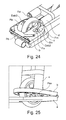
- FIG. 25 shows a detailed view showing that the two pistons (Pex) of the two ball fingers are automatically simultaneously pushed in during folding of the front base (b) against the central base (a) of the scooter;
- FIG. 26 a detailed view of the plate spring according to an exemplary embodiment of the present invention showing the plate spring in a lock position
- FIG. 27 a detailed view of the plate spring of FIG. 26 in an unlock position
- FIG. 28 shows a perspective front view of the three-piece scooter device of FIG. 1 showing the three piece scooter in a storage position.
- FIG. 1 The three-piece scooter device according to the invention is generally shown in FIG. 1 :
- the base (a), central part of the scooter includes, lengthwise, two aligned oblong median openings with the same dimensions (m) and (n), intended respectively to receive, after folding flat (FIG. 2 /) of the front part (b) and the rear part (c), respectively on hinges (h) and (h′) on the base (a) (hence the term three-piece), the front steering wheel (r) vertically integrated into a horizontal plate (u), held rotatably captive by (b), and the rear wheel (r′) arranged with a radial footbrake (s), secured to (c) by a known return spring means.
- (r) and (r′) are partially retracted into the thickness of their respective bases (b) and (c), and then additionally retracted into the thickness of the base (a) against which (b) and (c) are folded flat.
- the thickness of the bases is 2 cm, and the wheel diameter is 10 cm, after retraction the wheels still protrude by 6 cm cumulatively above and below the bases.
- the two rectilinear hinges (h) and (h′) are installed at the lower level of the junction edges of (b) and (c) with (a), so that in their configuration, even if no additional locking was provided between the plate (a) and the side parts (b) and (c), the scooter would remain compact during its use due to the user's weight.
- rear hinge (h′) ( FIG. 1 ) is interrupted, in its central portion, by the value of the diameter of a median cylindrical hole (t) diametrically overlapping between (a) and (c), the function of which will be described later.
- the hinge (h′) works in two in-line and symmetrical parts relative to the center of the hole (t) pierced so that the hinge line between (a) and (c) is diametric with (t).
- this median hole could also be provided to be oblong, and positioned longitudinally in two equal volumes on (a) and (c), symmetrically relative to a median width coinciding with the junction line of (a) and (c), with the aim of optimizing its function, as will be described later.
- (z 1 ) and (z 2 ) are identical and symmetrical relative to a median line that cuts (a) longitudinally, and likewise for (z 3 ) and (z 4 ), on the other hand on the base (a). All four of the tilting mechanisms of these toggles are installed on the central base (a), and the locking, strictly speaking, takes place inside facing notches (z 0 ) ( FIG. 1 ) on the side bases (b) and (c).
- the four toggles of the patent are identical.
- FIG. 9 shows in more detail how, specifically, the toggles (z 3 ) and (z 4 ) tilt to coplanarly lock (a) and (c).
- a Silentbloc (w′) made from rubber, Neoprene, or another specific material, formed on the edge of (a) or (c), or between (a) and (c) along the hinge (h′), interrupted like that hinge by the hole (t), secured to (a) or (c) by adhesion or clipping on the selected edge, is intended on the one hand to maintain the locking of (z 3 ) and (z 4 ) in tension, and thereby make the coplanar assembly more flexible through a very short-amplitude damping effect, and on the other hand to minimize any friction noise between (a) and (c) during the use of the scooter.
- FIG. 1 bis shows two identical junction devices bringing together (z 1 ) and (z 2 ) on the one hand and (z 3 ) and (z 4 ) on the other hand; these devices j) and j′), fitted into the base (a) and flush with its upper surface, simply consist of two respective connections of the levers of (z 1 ) and (z 2 ), and of (Z 3 ) and (z 4 ).
- the front and rear locking can easily be done by pushing in/clipping, with the front of the foot or the heel, the levers (j) and (j′), once the scooter is open and placed on the ground for use. It should be noted that preferably, (b) and (c) are theoretically provided with the same thicknesses as (a).
- the second folding step comprises unscrewing the two inwardly threaded sleeves (o) and (o′) that fix the steering unit saddle (d) (reinforced by a horizontal connection (d′) between its two vertical arms), on the rotary plate (u), symmetrically on either side of the wheel (r).
- the single-piece saddle (d) constitutes the bottom part of the steering column of the scooter; it is fixed and extends vertically ( FIG. 1 ) as far as the handlebars (g) by a cylindrical telescoping part made up of a fixed element (e) and a sliding element (f) in (e).
- the rotary plate (u) having, among other major functions, the function of vertically integrating, captive at the center of its volume, the front wheel (r) with its horizontal axis of rotation (G), fixed or mobile.
- FIG. 8 details the rotary plate (u) in its various elements stacked for the desired result of mobility of the front wheel (r) at 360°; other different stacks of circular pieces differently arranged of bearings or other rotation means limiting friction would allow equivalent results.
- (E) and (F) are the two faces of a thick circular skirt, integrated horizontally in a shoulder to the mass of the front base (b), and halfway through the thickness thereof.
- (E) and (F) support the rotary plate (u), captive of (b), in turn made up of two identical adjusted assemblies, circular and rotary by the bearing means, housed symmetrically, one against the lower part (F) of the skirt, the other against the upper part (E) of the skirt.
- the first assembly comprises a circular element (A) arranged longitudinally with an oblong central opening for the passage of the front wheel (r), this opening in turn being provided laterally with two hollow wheel axle supports (H), semi-cylindrical, median, face to face.
- A circular element
- H hollow wheel axle supports
- FIG. 7 details the operation of a single cylindrical Cardan joint (k) (identical to (k′)) made up of two symmetrical cylindrical axial articulations making it possible to go from verticality to 90°, and each provided with a bottom external threading ( 1 ) and a top external threading (I′), both working with the total internal threading of a sleeve (o), intended on the one hand to keep blocked in a line the two symmetrical articulations of a Cardan joint, by complete screwing of the sleeve encompassing them together, and on the other hand to keep the sleeve fixedly screwed above the articulation of the Cardan joint, after its release to allow its operation.
- FIG. 3 shows that the saddle (d) is centrally, perpendicularly and integrally extended by the following segment (e) of the steering column, which supports, at its base, two consecutive threaded sleeves (q) and (q′), identical, but with a larger diameter than (o) and (o′).
- the single Cardan joint (p) is, by its lower articulation, solidly vertically fixed by screwing blocked above and at the center of the saddle (d), lower portion of the steering column.
- FIG. 4 shows the released single Cardan (p), and positioned at a right angle so that the sleeve (q), then covering the intermediate cylindrical portion (v) and fixed by its inner thread on the upper articulation of (P), comes, in that angulation, to occupy vertically and midway through the volume, the thickness of the semi-cylindrical indentation (t′), obtained after folding (c) flat on (a), which transposes the middle hole (t) between (c) and (a), before folding down, in the indentation (t′) after.
- the hole (t) being cylindrical, the sleeve (q) overhangs the indentation (t′), i.e.
- the sleeve (q) in the vertical position can be adjusted without overhanging the indentation (t′), which is an advantage both in terms of volume and esthetics.
- the unscrewing of the sleeve (q′) frees the single Cardan joint (p′) and stays, through its inner threading, screwed above it on the outer threading of its upper articulation, overhanging the tube (e) that vertically extends the saddle (d) beyond the two Cardan joints.
- the final operation consists of tightening the annular fastener (x) to capture (f) in (e) ( FIG. 1 ).
- one of the original features of the inventive scooter is that its steering column is arranged for it to be folded in two parts positioned on either side of the bases. It is for this feature that one must obtain a sufficient steering column height so that the scooter may be used by adults, teens and children.
- the child scooter is characterized after folding by an extremely reduced bulk, allowing it to be transported inside a backpack, which can in turn be transported clipped on the scooter, using a traditional system.
- the robustness of the inventive scooter is obviously related to the solidity of the rotary plate (u), but that problem finds an appropriate solution in the compact configuration of the bearing cage on either side of the circular skirt secured to the plate (b) at mid-height thereof; the robustness of the scooter is primarily dependent on the strength of the hinges (h) and (h′) ( FIG.
- the force instantaneously exerted on the base (a) upon contact with the ground is exponential relative to the user's weight and is calculated using a complex formula depending on a large number of parameters, the most significant of which are: the user's weight, the speed of the scooter, the height of the fall, the length between the two wheel axles, the duration of the crash of the two wheels on the ground, and the nature of the ground.
- the two hinge lines (h) and (h′) can always be strengthened by increasing their dimensions to an acceptable working limit relative to the materials of which they are made; in particular, the diameters of the axles can be increased and one can choose very high-resistance steels for those axles, and technical tests may confirm sufficient robustness.
- FIGS. 16 and 17 show four protuberances with equal dimensions (L) and (L′), symmetrical to one another on the hinge side between (a) and (b), and (R) and (R′) symmetrical to one another on the hinge side between (a) and (c).
- the inventive scooter has the important feature, respecting all safety requirements, of being usable both by adults and children, owing to the particular specificity of its telescoping steering height that can vary from 65 cm to 1 m, and of being easy to fold manually in a very small volume.
- the diameter of the wheels should be provided around 10 cm.
- the scooter is at a height of about 5 cm from the ground for its user; at that height, there is little risk of leaning on the hip for the active leg, and skating is therefore made easier and is comfortable.
- this ground clearance of 5 cm can also be decreased for the youngest users; to that end, one need only chamfer the base (a) at the opposite edges of its two widths, by symmetrically freeing, on either side, the value of a planar section angle of several degrees (5° to 7°) between the planes of the edges of the bases (a) and (b) on the one hand, and the bases (a) and (c) on the other hand, these two planar section angles, preferably equivalent to one another, each having the corresponding hinge line for apex line.
- This operation can be optimized by chamfering the four contact edges between (a) and (b) on the one hand and (a) and (c) on the other hand, for the same section plane angle value (2.5° to 3.5°).
- the base (a) when the base (a) is 3.5 cm from the ground, if the handlebars are 1 m from the ground, it advances by about 10 cm toward the user.
- An additional improvement to comfort consists of the possibility, between two active periods, of having the user's mobile foot rest on a small, retractable horizontal support, vertically formed flush in the thickness of one of the two vertical supports making up the saddle (d), on the right for a righty, on the left for a lefty.
- the two oblong openings of the base (a) have a small width (the thickness of a wheel with only a very slight excess), and cannot present any danger of passing through, or laterally hindering the fixed foot, for the esthetics of the base, it could then be appropriate to conceal them when the scooter is in use. To that end, it would suffice to fix as a shoulder/flush on both openings, two clipped guards with the same dimensions, with small thicknesses, preferably obtained by injecting plastic material.
- these two guards could be released from the openings and stored vertically in the two detachable portions (g′) and (g′′) of the handlebars (g).
- said guards on the outer face thereof, could be grooved to make the base (a) ( FIG. 1 ) non-slip, the latter in turn being able to be grooved between the two guards for continuity of the grooves.
- the bases 12 , 13 and 14 have three options making it possible to fold and unfold the scooter much more quickly, practically semi-automatically: to quickly fold and unfold the steering column, the two single Cardans (q) and (q′) ( FIG. 1 ) should be replaced by a single hinge that is easy to lock and unlock using a device that we will call a “ball finger” (Dab) ( FIGS. 20 and 21 ).
- This device consists of a hollowed out cylinder at one end of which a piston/spring operates making it possible to produce strong locking by simultaneously activating, via a device inside the cylinder, two symmetrically opposite balls, held captive by the cylinder.
- a piston/spring When the piston/spring is in the inner position (Pin) ( FIG. 20 ), the two balls (Bin) are flush with, without protruding past, the outer surface of the entire cylinder of the ball finger; when the piston/spring is in the outer position (Pex) ( FIG. 21 ), the two balls (Bex) ( FIG.
- the piston/spring still remains external after locking or unlocking.
- a ball finger (Dab) ( FIG. 22 )
- FIG. 22 For rapid, or even automatic, folding and unfolding of the steering column, installing a ball finger (Dab) ( FIG. 22 ), fixed centrally and vertically in the body of the fixed portion of the hinge (Cb 2 ) ( FIG. 22 makes it possible to keep the hinge closed, and therefore the steering column blocked in line ( FIG. 23 ), the two balls (Bex) ( FIG. 22 iametric, then being located in the external position blocked in a suitable central circular opening (Tr) ( FIG. 22 ) of the mobile portion (Cb 1 )) of the hinge.
- Simple pressure on the piston/spring (Pex) ( FIG. 22 ) of the ball finger makes it possible to lock the hinge automatically, and the folding of the steering column follows.
- the pressure of the piston/spring can be exerted automatically, once the two elements of the steering column are put in line on either side of their shared hinge (Cb 1 /Cb 2 ), by the action of the internal telescoping tube (f) ( FIG. 1 ) at the upper cylindrical portion of the steering column (e) ( FIG. 1 ), then abutting on the piston/spring of a ball finger fixed centrally in the mobile portion (Cb 1 )) of the hinge, which enables automatic unlocking thereof at the end of removal of the telescoping tube (f).
- This Figure shows that the symmetrical single Cardans (k) and (k′) have been replaced in their respective geometric spaces by two symmetrical hinges whereof the two fixed portions (Fix) ( FIG. 24 ) are incorporated into the mobile horizontal plate (u), and whereof the two mobile portions (Fm) ( FIG. 24 ), working with the preceding parts, are arranged at the two circular bases of the saddle (d).
- FIG. 25 also shows that the two pistons (Pex) of the two ball fingers are automatically simultaneously pushed in during folding of the front base (b) against the central base (a) of the scooter, which results in automatically unlocking the two hinges, and the folding of the saddle follows.
- the principle of the ball finger can lead to the idea of replacing the balls with preferably cylindrical elements allowing a much longer protrusion outside by the cylinder than the balls for deeper catching and ten times the mechanical strength of the locking.
- One may provide, arranged concentrically to the ball finger, a gripping system using a toothed wheel making it possible to eliminate any play in the hinges after locking.
- the hinge of the steering column as well as the two hinges of the saddle must, for safety reasons, have their respective axles toward the scooter's user, so as to offer the best possible strength of the steering column in case of collision of the front wheel.
- the overall configuration of the steering enables that safety.
- An improvement can also be made to coplanarly secure the central base (a) with the front base (b), before using the scooter.
- FIGS. 26 and 27 show, and consists of a thick plate spring (RI) ( FIG. 26 ) preferably fixed concentrically to the mobile horizontal plate (u) and on the base (b), or incorporated into the thickness of the base (b) symmetrically on the arc of circle of the fixed base of the plate juxtaposing the hinge between (a) and (b).
- RI thick plate spring
- This plate spring (R 1 ) is formed by a longitudinal return in the form of a tab (L 1 ) ( FIG. 26 ), which is characterized by a fixed angulation, pseudo-perpendicular (by default) to the plane of (R 1 ); the tab (L 1 ) slightly protrudes from the plane of the base (b) to allow it to be locked in a longitudinal groove (G 1 ) ( FIG. 26 ) of the base (a) parallel to the connecting axle between (a) and (b).
- (L 1 ) and (G 1 ) thus operate relative to one another by locking/unlocking, to secure, coplanar, or separate the bases (a) and (b).
- FIG. 26 shows how the tab (L 1 ) of the spring (R 1 ) is positioned longitudinally at the end of the base (b) on the base (a) of the scooter.
- the tab (L 1 ) may be provided to be much longer and taller than that shown in for better catching, which assumes that the groove (G 1 ) respectively has the same length and depth.
- the tab (L 1 ) after folding, the tab (L 1 ) must not overhang the structure of the scooter beyond the connecting axle between the bases (a) and (b) parallel to it; the pseudo-angulation of less than 90° of the tab (L 1 ) with the plane of the spring (RI) makes it possible to avoid any possibility of catching, while strengthening the coplanar locking of (a) and (b). Lastly, the tab (L 1 ) must form, with the plane of (R 1 ), an angulation smaller than 90° to avoid any catching problem.
Applications Claiming Priority (3)
| Application Number | Priority Date | Filing Date | Title |
|---|---|---|---|
| FR1004694 | 2010-12-02 | ||
| FR1004694A FR2968266B1 (fr) | 2010-12-02 | 2010-12-02 | Trottinette triptyque pliante a roues escamotables |
| PCT/FR2011/000610 WO2012072893A1 (fr) | 2010-12-02 | 2011-11-18 | Trottinette triptyque pliante a roues escamotables |
Publications (2)
| Publication Number | Publication Date |
|---|---|
| US20120256386A1 US20120256386A1 (en) | 2012-10-11 |
| US8465033B2 true US8465033B2 (en) | 2013-06-18 |
Family
ID=44474996
Family Applications (1)
| Application Number | Title | Priority Date | Filing Date |
|---|---|---|---|
| US13/503,915 Active US8465033B2 (en) | 2010-12-02 | 2011-11-18 | Three-piece folding scooter |
Country Status (7)
| Country | Link |
|---|---|
| US (1) | US8465033B2 (fr) |
| EP (1) | EP2780219B1 (fr) |
| CN (1) | CN104024098B (fr) |
| ES (1) | ES2605492T3 (fr) |
| FR (1) | FR2968266B1 (fr) |
| TW (1) | TWI555669B (fr) |
| WO (1) | WO2012072893A1 (fr) |
Cited By (8)
| Publication number | Priority date | Publication date | Assignee | Title |
|---|---|---|---|---|
| US20130306392A1 (en) * | 2011-02-11 | 2013-11-21 | Antonius Bernardus Schaap | Foldable Scooter |
| US8720918B2 (en) * | 2012-07-05 | 2014-05-13 | Xin Xin Li Bicycle Fittings (Shenzhen) Co., Ltd. | Foldable scooter |
| US20150035257A1 (en) * | 2012-02-13 | 2015-02-05 | RoadIX Urban Transportation Ltd. | Urban vehicle |
| US20150158543A1 (en) * | 2012-02-22 | 2015-06-11 | Jarbas Braga Neto | Transportation device |
| US9187144B2 (en) * | 2014-03-21 | 2015-11-17 | Fook Fah Yap | Folding scooter |
| US9376158B1 (en) | 2015-03-05 | 2016-06-28 | Probity Cell LLC | Portable conveyance with towing guide assembly |
| US10486763B2 (en) | 2017-01-04 | 2019-11-26 | Hyundai Motor Company | Folding personal mobility vehicle |
| US10870460B2 (en) | 2017-12-29 | 2020-12-22 | Fook Fah Yap | Compact folding electric bicycle |
Families Citing this family (33)
| Publication number | Priority date | Publication date | Assignee | Title |
|---|---|---|---|---|
| US20130062846A1 (en) * | 2011-09-09 | 2013-03-14 | Sunpex Technology Co., Ltd. | Collapsible frame structure of scooter |
| US9643077B2 (en) * | 2013-10-21 | 2017-05-09 | Equalia LLC | Pitch-propelled vehicle |
| US9211470B2 (en) | 2013-10-21 | 2015-12-15 | Equalia LLC. | Pitch-propelled vehicle |
| US10369453B2 (en) | 2013-10-21 | 2019-08-06 | Equalia LLC | Pitch-propelled vehicle |
| US9482508B2 (en) * | 2014-03-27 | 2016-11-01 | Johnson Level & Tool Mfg. Co., Inc. | Measuring wheel with folding handle |
| CN104527879A (zh) * | 2015-01-05 | 2015-04-22 | 重庆银钢科技(集团)有限公司 | 一种电动车 |
| CN104709421B (zh) * | 2015-03-06 | 2017-07-18 | 周晓菲 | 一种便携式两轮车的前轮轮毂内转向结构 |
| CN104691689B (zh) * | 2015-03-25 | 2017-06-30 | 深圳乐行天下科技有限公司 | 一种锁定解锁装置及滑板车 |
| US9493206B1 (en) * | 2015-04-28 | 2016-11-15 | Steve Oh | Transformable folding electric scooter |
| FR3036367B1 (fr) * | 2015-05-19 | 2018-06-22 | Henri Bigot | Trottinette pliable |
| CN104973189A (zh) * | 2015-08-05 | 2015-10-14 | 姜夏芸 | 便利滑板车 |
| CN105129008B (zh) * | 2015-09-29 | 2017-12-12 | 泉州市泉港凯威信息技术咨询有限公司 | Z形折叠坐式三轮滑板车 |
| DE102016210107B3 (de) * | 2016-06-08 | 2017-07-13 | Magna Exteriors Gmbh | Elektromotorisierter Tretroller |
| CN107539407B (zh) * | 2016-06-29 | 2023-01-13 | 广州道动新能源有限公司 | 可折叠的交通工具 |
| CN106080911B (zh) * | 2016-07-15 | 2019-02-19 | 南通市宏品金属制品有限公司 | 折叠式滑板车 |
| KR102150090B1 (ko) * | 2016-08-17 | 2020-08-31 | 주식회사 크림슨 | 캐리어형 접이식 킥보드 |
| CN106335589A (zh) * | 2016-09-22 | 2017-01-18 | 欧阳昌俊 | 一种可折叠滑板车 |
| DE102017216356A1 (de) * | 2016-11-10 | 2018-05-17 | Ford Motor Company | Kraftfahrzeug |
| KR101918368B1 (ko) * | 2016-12-16 | 2018-11-13 | 현대자동차주식회사 | 접이식 퍼스널 모빌리티 |
| CN106428345A (zh) * | 2016-12-16 | 2017-02-22 | 张家港市联盛塑业有限公司 | 一种金属滑板车 |
| CN206427191U (zh) * | 2016-12-21 | 2017-08-22 | 深圳乐行天下科技有限公司 | 折叠机构及具有其的滑板车 |
| USD843483S1 (en) * | 2017-01-23 | 2019-03-19 | Chongqing Yingang Technology (Group) Co., Ltd. | Remote control scooter with four wheels |
| US10881898B2 (en) | 2017-07-25 | 2021-01-05 | Justin Petersen | Exercise device and methods |
| CN107651081B (zh) * | 2017-11-08 | 2024-01-19 | 兰溪普泰工贸有限公司 | 滑板车及折叠机构和其折叠、锁紧方法 |
| GB2571113B (en) * | 2018-02-16 | 2020-06-17 | Fleet Action Sports Ltd | Trampoline Scooter |
| TWI696565B (zh) * | 2018-12-26 | 2020-06-21 | 伍氏科技股份有限公司 | 代步車之饋縮式收合狀態鎖定結構 |
| FR3096023B1 (fr) * | 2019-05-13 | 2022-03-25 | Bigben Connected | Trottinette sécurisable |
| CN110341861A (zh) * | 2019-08-20 | 2019-10-18 | 南京金百合医疗器械有限公司 | 手动折叠伸缩的电动代步车 |
| EP3845443A1 (fr) * | 2020-01-03 | 2021-07-07 | RAFA Design & Innovations Inc. | Scooter pliable |
| DE102020133679A1 (de) * | 2020-12-16 | 2022-06-23 | Bayerische Motoren Werke Aktiengesellschaft | Elektrokleinstfahrzeug |
| CN112896398B (zh) * | 2021-02-25 | 2022-05-27 | 仲恺农业工程学院 | 基于绿色出行的人力滑板车 |
| CN113788208B (zh) * | 2021-09-18 | 2023-07-11 | 江苏机替科技有限公司 | 用于折叠踏板车的包装盒及包装方式 |
| CN114305895A (zh) * | 2022-01-06 | 2022-04-12 | 恩比尔(厦门)机械制造有限公司 | 一种车把可调的轮椅 |
Citations (3)
| Publication number | Priority date | Publication date | Assignee | Title |
|---|---|---|---|---|
| US20080084034A1 (en) * | 2006-10-10 | 2008-04-10 | Viktor Feldman | Personnel transportation devices |
| US7581739B2 (en) * | 2007-12-21 | 2009-09-01 | Pluto Technologies, Inc. | Skateboard deck and spring-based truck |
| US20120104714A1 (en) * | 2009-06-02 | 2012-05-03 | Riccardo Nimrod Sapir | Folding wheel mechanism for vechile |
Family Cites Families (6)
| Publication number | Priority date | Publication date | Assignee | Title |
|---|---|---|---|---|
| WO1998046474A2 (fr) * | 1997-04-15 | 1998-10-22 | Empower Corporation | Trottinette portable |
| DE19757867A1 (de) * | 1997-12-24 | 1999-07-01 | Guenter Hafner | Klappbares Transportfahrzeug |
| AT407519B (de) * | 1999-03-25 | 2001-04-25 | Neuhold Erwin | Zusammenlegbarer tretroller |
| CN2422028Y (zh) * | 2000-04-27 | 2001-03-07 | 田丰益 | 滑板车收合结构 |
| CN2425676Y (zh) * | 2000-05-19 | 2001-04-04 | 唐煜文 | 一种折叠式滑板车 |
| TWM334089U (en) * | 2007-12-31 | 2008-06-11 | Tsann Kuen Entpr Co Ltd | Structure of foldable scooter |
-
2010
- 2010-12-02 FR FR1004694A patent/FR2968266B1/fr active Active
-
2011
- 2011-11-18 EP EP11799738.7A patent/EP2780219B1/fr active Active
- 2011-11-18 ES ES11799738.7T patent/ES2605492T3/es active Active
- 2011-11-18 US US13/503,915 patent/US8465033B2/en active Active
- 2011-11-18 CN CN201180074937.8A patent/CN104024098B/zh active Active
- 2011-11-18 WO PCT/FR2011/000610 patent/WO2012072893A1/fr active Application Filing
- 2011-12-01 TW TW100144110A patent/TWI555669B/zh active
Patent Citations (3)
| Publication number | Priority date | Publication date | Assignee | Title |
|---|---|---|---|---|
| US20080084034A1 (en) * | 2006-10-10 | 2008-04-10 | Viktor Feldman | Personnel transportation devices |
| US7581739B2 (en) * | 2007-12-21 | 2009-09-01 | Pluto Technologies, Inc. | Skateboard deck and spring-based truck |
| US20120104714A1 (en) * | 2009-06-02 | 2012-05-03 | Riccardo Nimrod Sapir | Folding wheel mechanism for vechile |
Cited By (11)
| Publication number | Priority date | Publication date | Assignee | Title |
|---|---|---|---|---|
| US20130306392A1 (en) * | 2011-02-11 | 2013-11-21 | Antonius Bernardus Schaap | Foldable Scooter |
| US8887852B2 (en) * | 2011-02-11 | 2014-11-18 | Trikelet B.V. | Foldable scooter |
| US20150035257A1 (en) * | 2012-02-13 | 2015-02-05 | RoadIX Urban Transportation Ltd. | Urban vehicle |
| US9272739B2 (en) * | 2012-02-13 | 2016-03-01 | RoadIX Urban Transportation Ltd. | Urban vehicle |
| US20150158543A1 (en) * | 2012-02-22 | 2015-06-11 | Jarbas Braga Neto | Transportation device |
| US8720918B2 (en) * | 2012-07-05 | 2014-05-13 | Xin Xin Li Bicycle Fittings (Shenzhen) Co., Ltd. | Foldable scooter |
| US9187144B2 (en) * | 2014-03-21 | 2015-11-17 | Fook Fah Yap | Folding scooter |
| US9376158B1 (en) | 2015-03-05 | 2016-06-28 | Probity Cell LLC | Portable conveyance with towing guide assembly |
| US9586643B2 (en) | 2015-03-05 | 2017-03-07 | Probity Cell LLC | Portable conveyance with towing guide assembly |
| US10486763B2 (en) | 2017-01-04 | 2019-11-26 | Hyundai Motor Company | Folding personal mobility vehicle |
| US10870460B2 (en) | 2017-12-29 | 2020-12-22 | Fook Fah Yap | Compact folding electric bicycle |
Also Published As
| Publication number | Publication date |
|---|---|
| CN104024098B (zh) | 2017-02-15 |
| FR2968266B1 (fr) | 2012-12-21 |
| WO2012072893A1 (fr) | 2012-06-07 |
| CN104024098A (zh) | 2014-09-03 |
| EP2780219A1 (fr) | 2014-09-24 |
| WO2012072893A8 (fr) | 2012-08-16 |
| TWI555669B (zh) | 2016-11-01 |
| TW201235255A (en) | 2012-09-01 |
| EP2780219B1 (fr) | 2016-09-14 |
| US20120256386A1 (en) | 2012-10-11 |
| ES2605492T3 (es) | 2017-03-14 |
| FR2968266A1 (fr) | 2012-06-08 |
Similar Documents
| Publication | Publication Date | Title |
|---|---|---|
| US8465033B2 (en) | Three-piece folding scooter | |
| RU2613651C2 (ru) | Самокат | |
| US7156405B1 (en) | Folding scooter | |
| US9120523B2 (en) | Foldable frame for two-wheel vehicle | |
| US7862479B2 (en) | Foldable trampoline and conversion kit | |
| US7407172B2 (en) | Flooding scooter with wide lever | |
| US20110193313A1 (en) | Foldable bicycle | |
| US20020180169A1 (en) | Kick boards | |
| KR20130048542A (ko) | 접철식 퀵보드 | |
| JP2019531116A (ja) | がたつき防止折りたたみスクーター | |
| CN107097883B (zh) | 一种折叠机构及滑板车 | |
| EP2476608A1 (fr) | Dispositif de joint repliable | |
| CN205707078U (zh) | 一种折叠滑板车 | |
| FR2980226A1 (fr) | Garde corps de securite pour toiture inaccessible au public | |
| US20090057082A1 (en) | Push suitcase | |
| JP5930054B2 (ja) | 収納可能な車輪を有する3部構成の折り畳みスクーター | |
| WO2010050803A2 (fr) | Construction à charnière verrouillable | |
| KR20170141430A (ko) | 킥스쿠터의 절첩방법 | |
| US8033514B2 (en) | Motorcycle stand | |
| KR102123161B1 (ko) | 이동수단용 폴딩구조 | |
| WO2000022951A1 (fr) | Parapluie | |
| KR200202860Y1 (ko) | 스쿠터의 절첩장치 | |
| US20080252027A1 (en) | Golf Trolley with Easy-Collapsed Auxiliary Wheel | |
| CN214729385U (zh) | 折叠装置和电动车 | |
| KR101949307B1 (ko) | 접이식 보드 자전거 |
Legal Events
| Date | Code | Title | Description |
|---|---|---|---|
| STCF | Information on status: patent grant |
Free format text: PATENTED CASE |
|
| FPAY | Fee payment |
Year of fee payment: 4 |
|
| MAFP | Maintenance fee payment |
Free format text: PAYMENT OF MAINTENANCE FEE, 8TH YR, SMALL ENTITY (ORIGINAL EVENT CODE: M2552); ENTITY STATUS OF PATENT OWNER: SMALL ENTITY Year of fee payment: 8 |