US8028552B2 - Structure of automobile electronic key for security and method for performing function thereof - Google Patents
Structure of automobile electronic key for security and method for performing function thereof Download PDFInfo
- Publication number
- US8028552B2 US8028552B2 US12/178,468 US17846808A US8028552B2 US 8028552 B2 US8028552 B2 US 8028552B2 US 17846808 A US17846808 A US 17846808A US 8028552 B2 US8028552 B2 US 8028552B2
- Authority
- US
- United States
- Prior art keywords
- key
- locking member
- car
- ignition knob
- key fob
- Prior art date
- Legal status (The legal status is an assumption and is not a legal conclusion. Google has not performed a legal analysis and makes no representation as to the accuracy of the status listed.)
- Expired - Fee Related, expires
Links
Images


Classifications
-
- G—PHYSICS
- G07—CHECKING-DEVICES
- G07C—TIME OR ATTENDANCE REGISTERS; REGISTERING OR INDICATING THE WORKING OF MACHINES; GENERATING RANDOM NUMBERS; VOTING OR LOTTERY APPARATUS; ARRANGEMENTS, SYSTEMS OR APPARATUS FOR CHECKING NOT PROVIDED FOR ELSEWHERE
- G07C9/00—Individual registration on entry or exit
- G07C9/00174—Electronically operated locks; Circuits therefor; Nonmechanical keys therefor, e.g. passive or active electrical keys or other data carriers without mechanical keys
- G07C9/00309—Electronically operated locks; Circuits therefor; Nonmechanical keys therefor, e.g. passive or active electrical keys or other data carriers without mechanical keys operated with bidirectional data transmission between data carrier and locks
-
- B—PERFORMING OPERATIONS; TRANSPORTING
- B60—VEHICLES IN GENERAL
- B60R—VEHICLES, VEHICLE FITTINGS, OR VEHICLE PARTS, NOT OTHERWISE PROVIDED FOR
- B60R25/00—Fittings or systems for preventing or indicating unauthorised use or theft of vehicles
- B60R25/01—Fittings or systems for preventing or indicating unauthorised use or theft of vehicles operating on vehicle systems or fittings, e.g. on doors, seats or windscreens
- B60R25/02—Fittings or systems for preventing or indicating unauthorised use or theft of vehicles operating on vehicle systems or fittings, e.g. on doors, seats or windscreens operating on the steering mechanism
- B60R25/021—Fittings or systems for preventing or indicating unauthorised use or theft of vehicles operating on vehicle systems or fittings, e.g. on doors, seats or windscreens operating on the steering mechanism restraining movement of the steering column or steering wheel hub, e.g. restraining means controlled by ignition switch
- B60R25/0215—Fittings or systems for preventing or indicating unauthorised use or theft of vehicles operating on vehicle systems or fittings, e.g. on doors, seats or windscreens operating on the steering mechanism restraining movement of the steering column or steering wheel hub, e.g. restraining means controlled by ignition switch using electric means, e.g. electric motors or solenoids
-
- B—PERFORMING OPERATIONS; TRANSPORTING
- B60—VEHICLES IN GENERAL
- B60R—VEHICLES, VEHICLE FITTINGS, OR VEHICLE PARTS, NOT OTHERWISE PROVIDED FOR
- B60R25/00—Fittings or systems for preventing or indicating unauthorised use or theft of vehicles
- B60R25/01—Fittings or systems for preventing or indicating unauthorised use or theft of vehicles operating on vehicle systems or fittings, e.g. on doors, seats or windscreens
- B60R25/04—Fittings or systems for preventing or indicating unauthorised use or theft of vehicles operating on vehicle systems or fittings, e.g. on doors, seats or windscreens operating on the propulsion system, e.g. engine or drive motor
-
- B—PERFORMING OPERATIONS; TRANSPORTING
- B60—VEHICLES IN GENERAL
- B60R—VEHICLES, VEHICLE FITTINGS, OR VEHICLE PARTS, NOT OTHERWISE PROVIDED FOR
- B60R25/00—Fittings or systems for preventing or indicating unauthorised use or theft of vehicles
- B60R25/20—Means to switch the anti-theft system on or off
- B60R25/2063—Ignition switch geometry
-
- B—PERFORMING OPERATIONS; TRANSPORTING
- B60—VEHICLES IN GENERAL
- B60R—VEHICLES, VEHICLE FITTINGS, OR VEHICLE PARTS, NOT OTHERWISE PROVIDED FOR
- B60R25/00—Fittings or systems for preventing or indicating unauthorised use or theft of vehicles
- B60R25/20—Means to switch the anti-theft system on or off
- B60R25/22—Means to switch the anti-theft system on or off using mechanical identifiers
-
- B—PERFORMING OPERATIONS; TRANSPORTING
- B60—VEHICLES IN GENERAL
- B60R—VEHICLES, VEHICLE FITTINGS, OR VEHICLE PARTS, NOT OTHERWISE PROVIDED FOR
- B60R25/00—Fittings or systems for preventing or indicating unauthorised use or theft of vehicles
- B60R25/20—Means to switch the anti-theft system on or off
- B60R25/24—Means to switch the anti-theft system on or off using electronic identifiers containing a code not memorised by the user
-
- G—PHYSICS
- G07—CHECKING-DEVICES
- G07C—TIME OR ATTENDANCE REGISTERS; REGISTERING OR INDICATING THE WORKING OF MACHINES; GENERATING RANDOM NUMBERS; VOTING OR LOTTERY APPARATUS; ARRANGEMENTS, SYSTEMS OR APPARATUS FOR CHECKING NOT PROVIDED FOR ELSEWHERE
- G07C9/00—Individual registration on entry or exit
- G07C9/00174—Electronically operated locks; Circuits therefor; Nonmechanical keys therefor, e.g. passive or active electrical keys or other data carriers without mechanical keys
- G07C9/00309—Electronically operated locks; Circuits therefor; Nonmechanical keys therefor, e.g. passive or active electrical keys or other data carriers without mechanical keys operated with bidirectional data transmission between data carrier and locks
- G07C2009/00507—Electronically operated locks; Circuits therefor; Nonmechanical keys therefor, e.g. passive or active electrical keys or other data carriers without mechanical keys operated with bidirectional data transmission between data carrier and locks keyless data carrier having more than one function
- G07C2009/00547—Electronically operated locks; Circuits therefor; Nonmechanical keys therefor, e.g. passive or active electrical keys or other data carriers without mechanical keys operated with bidirectional data transmission between data carrier and locks keyless data carrier having more than one function starting ignition
-
- Y—GENERAL TAGGING OF NEW TECHNOLOGICAL DEVELOPMENTS; GENERAL TAGGING OF CROSS-SECTIONAL TECHNOLOGIES SPANNING OVER SEVERAL SECTIONS OF THE IPC; TECHNICAL SUBJECTS COVERED BY FORMER USPC CROSS-REFERENCE ART COLLECTIONS [XRACs] AND DIGESTS
- Y10—TECHNICAL SUBJECTS COVERED BY FORMER USPC
- Y10T—TECHNICAL SUBJECTS COVERED BY FORMER US CLASSIFICATION
- Y10T70/00—Locks
- Y10T70/50—Special application
- Y10T70/5889—For automotive vehicles
- Y10T70/5956—Steering mechanism with switch
-
- Y—GENERAL TAGGING OF NEW TECHNOLOGICAL DEVELOPMENTS; GENERAL TAGGING OF CROSS-SECTIONAL TECHNOLOGIES SPANNING OVER SEVERAL SECTIONS OF THE IPC; TECHNICAL SUBJECTS COVERED BY FORMER USPC CROSS-REFERENCE ART COLLECTIONS [XRACs] AND DIGESTS
- Y10—TECHNICAL SUBJECTS COVERED BY FORMER USPC
- Y10T—TECHNICAL SUBJECTS COVERED BY FORMER US CLASSIFICATION
- Y10T70/00—Locks
- Y10T70/70—Operating mechanism
- Y10T70/7441—Key
Definitions
- the present invention relates to a structure of an automobile electronic key for security and a method for performing the function thereof, and more particularly, to a structure of an automobile electronic key for security and a method for performing the function thereof, which allow a proper user to insert the key of an automobile and rotate the inserted key to operate steering and start the engine of an automobile.
- an ignition lock device of an automobile is also called a start switch for starting the engine of the automobile and integrated with a locking device of a steering column in order to prevent the automobile from being stolen.
- the ignition lock device of an automobile is fixed to a steering column connected to a steering wheel and includes a key hole into which a car key is inserted by a driver. That is, the ignition lock device includes an ignition lock into which a car key is inserted, a key cylinder rotated with the car key being inserted into the ignition lock such that the car key operates, and an ignition lock body for performing a locking operation according to the operating state of the key cylinder, and the state of the automobile is changed according to the rotating operation of the car key.
- the rotating operation of the car key is composed of four steps of a locking step, an accessory power supply step, a controller and driver on step, and a starting step. The car key is inserted into or ejected from the ignition lock only in the locking step.
- the aforementioned conventional ignition lock device is a mechanical lock device provided near a car door locking unit and the steering column.
- This mechanical lock device operates according to the rotating operation of the car key inserted by a driver to start the engine or cancel a locked state of the steering column.
- the conventional mechanical lock device requires the driver to insert the car key thereinto and rotate the car key. Furthermore, even though the conventional mechanical lock device is damaged, the engine can be started through a simple operation. Accordingly, the automobile having the mechanical lock device is easily stolen.
- a smart key is provided to some of recent automobiles on the market.
- the car using the smart key has a key cylinder and a steering column in modified structures such that the car key cannot be inserted into the key cylinder when normal authentication is not performed.
- a user can lock/unlock the doors of the car only using the smart key and start the car according to an authentication result without inserting the car key into the key cylinder.
- a structure of an automobile electronic key for security comprises an ignition knob body, an ignition knob rotator, a rotation axis, a locking member, and a controller.
- the ignition knob body is provided at the front of a key cylinder into which a car key is inserted.
- the ignition knob rotator is provided at the front of the ignition knob body and includes an actuator operating according to a driving signal.
- the rotation axis is located inside the ignition knob body in parallel with the axial direction of the key cylinder and moved such that the car key is switched to an insertion available state or an insertion unavailable state according to the position of the rotation axis.
- the locking member is located inside the ignition knob rotator on one side of the central axis of the key cylinder and moved in parallel with the axial direction of the key cylinder such that the car key is switched to a rotatable state or unrotatable state according to the position of the locking member.
- the controller performs authentication on a key fob and drives the actuator according to whether the key fob passes authentication to move the locking member such that the car key is switched to the rotatable state or the unrotatable state.
- a method for performing the function of an automobile electronic key structure for security comprises the steps of determining whether at least one of a driver seat door closing signal and a brake pedal signal is on, requesting a key fob of an automobile to send the ID thereof and receiving the ID from the key fob when at least one of the driver seat door closing signal and the brake pedal signal is on, authenticating the key fob using the received ID, and driving an actuator to move a locking member such that a car key is switched to a rotatable state when the key fob passes authentication and driving the actuator to move the locking member such that the car key is switched to an unrotatable state when the key fob does not pass authentication.
- the ignition knob that can be locked and released at a low cost without changing the structures of the existing steering column and key cylinder.
- the proper user can start the engine of the automobile with a simple operation.
- FIG. 1 is a cross-sectional view of a structure of an automobile electronic key for security according to an embodiment of the present invention
- FIGS. 2A , 2 B, 2 C and 2 D are views for explaining the operating principle of the structure of the automobile electronic key for security according to the present invention.
- FIGS. 3A and 3B are exemplary views showing operations of a locking member and an actuator in the structure of the automobile electronic key for security according to the present invention
- FIG. 4 is a view showing the internal configuration of a controller in the structure of the automobile electronic key for security according to the present invention.
- FIG. 5 is a flow chart of a method for performing the function of the structure of the automobile electronic key for security according to the present invention.
- FIG. 1 is a cross-sectional view of a structure of an automobile electronic key for security according to an embodiment of the present invention.
- the structure of the automobile electronic key for security includes an ignition knob body 200 , an ignition knob rotator 300 , and a controller 400 .
- the ignition knob body 200 is provided at the front of a key cylinder 100 .
- the ignition knob rotator 300 is provided at the front of the ignition knob body 200 .
- the controller 400 is connected to the ignition knob rotator 300 through a wire and transmits/receives signals to/from the ignition knob rotator 300 .
- a car key 101 is inserted into the key cylinder 100 and a power mode of the automobile is changed according to the rotating state of the inserted car key 101 . That is, the car key 101 is rotated through four steps of a locking step, an accessory power supply step, a controller and driver on step, and a starting step while being inserted into the key cylinder 100 , and thus the power mode of the automobile is changed according to the rotating state of the car key 101 .
- the ignition knob body 200 is provided at the front of the key cylinder 100 . Particularly, it is desirable that the ignition knob body 200 is separated from the key cylinder 100 . Accordingly, the ignition knob body 200 and the key cylinder 100 are combined with each other when the car key having a mechanical structure is inserted thereinto.
- the ignition knob body 200 has a cylindrical shape and is fixed onto a steering column connected to a steering wheel of the automobile.
- the ignition knob body 200 includes a first spring 201 , a connecting part 202 , a rotation axis 203 and a locking hole 204 .
- the firs spring 201 automatically ejects the car key 101 being inserted into the key cylinder 100 and the ignition knob body 200 according to elasticity in the locking step.
- the connecting part 202 is formed in a cylindrical shape in the ignition knob body 200 , perpendicularly to the axis of the key cylinder 100 , and has a low height. In view of the functional side, the connecting part 202 connects the key cylinder 100 and the ignition knob body 200 between the key cylinder 100 and the ignition knob body 200 .
- the rotation axis 203 is located at the front of the connecting part 202 in the ignition knob body 200 .
- the rotation axis 203 has a predetermined length in parallel with the axial direction of the key cylinder 100 and is connected to a central hole of the ignition knob rotator 300 . It is desirable that the rotation axis 203 is formed in the shape of a cylinder longer than the connecting part 202 in parallel with the axial direction of the key cylinder 100 . It is desirable that the rotation axis 203 is attached to the front of the connecting part 202 and integrated with the connecting part 202 . In view of the functional side, the rotation axis 203 is moved to switch the car key 101 to an insertion available state or an insertion unavailable state according to the position of the rotation axis 203 . That is, when the rotation axis 203 integrated with the connecting part 202 is moved to push the car key 101 according to elasticity of the first spring 201 , the car key 101 is inserted into the key cylinder 100 .
- the locking hole 204 is formed on a circular plate provided at the front of the connecting part 202 and located on one side of the central axis of the key cylinder 100 such that the locking hole 204 corresponds to a locking member 310 . That is, the locking hole 204 is formed at the back of the ignition knob rotator 300 . It is desirable that the locking member 310 is formed in a cylindrical shape.
- the locking hole 204 can be a circular hole having a diameter greater than that of the circular shape of the cross section of the end of the locking member 210 such that the locking hole 204 and the circular shape of the locking member 210 can be combined with each other. In view of the functional side, the locking hole 204 guides the locking member to move and the car key 101 cannot be rotated when the locking member 310 is moved into the locking hole 204 .
- the ignition knob rotator 300 is provided at the front of the ignition knob body 200 , formed in a cylindrical shape and includes a second spring 311 and an actuator 320 .
- the locking member 310 is located on one side of the central axis of the key cylinder 100 .
- the car key 101 is switched to a rotatable state when the locking member 310 is ejected from the locking hole 204 and the car key 101 is switched to an unrotatable state when the locking member 310 is inserted into the locking hole 204 . That is, the locking member 310 is moved in parallel with the axial direction of the key cylinder 100 such that the car key 101 is switched to the rotatable state or the unrotatable state according to the position of the moved locking member 310 .
- the second spring 311 automatically moves the locking member 310 that operates by current to the inside of an electromagnet 321 according to elasticity when there is no current supply according to a control signal from the controller 400 .
- the actuator 320 includes the electromagnet 321 and a polarity converter 322 .
- the electromagnet 321 wound by a coil in a predetermined solenoid form. It is desirable that the polarity converter 322 is connected to both ends of the electromagnet 321 through terminals. While the polarity converter 322 surrounds the electromagnet 321 in FIG. 1 , the polarity converter 322 can be located at a distance from the electromagnet 321 . In view of the functional side, the polarity converter 322 converts polarities of both ends of the electromagnet 321 . It is desirable that the locking member 310 is inserted into and ejected from the locking hole 204 according to polarity change in the electromagnet 321 .
- the controller 400 receives the ID of a key fob 500 carried by an automobile user (driver) through wireless communication with the key fob 500 and performs authentication on the key fob 500 using the received ID.
- the controller 400 controls the actuator 320 to operate to move the locking member 310 such that the car key 101 is switched to the rotatable state.
- the key fob 500 includes its ID having information on a proper user of the automobile.
- the key fob 500 includes a battery (not shown), and thus the key fob 500 can perform wireless communication with the controller 400 when approaching or entering the automobile. That is, controller 400 performs wireless communication with the key fob through an antenna attached to the inside of the automobile.
- the controller 400 is connected to a driver seat door closing sensing switch and a brake pedal switch (not shown) to sense whether a driver seat door is closed and a brake pedal is stepped on. That is, the controller 400 starts to communicate with the key fob 500 when the driver seat door is closed or the driver steps on a brake pedal. The controller 400 unlocks the locking member 204 after authentication of the key fob 500 through communication with the key fob 500 to prevent the automobile from abnormally suddenly starting.
- the controller 400 requests the key fob 500 to send the ID thereof through wireless communication and receives the ID from the key fob 500 when a driver seat door closing signal or a brake pedal signal provided to the automobile are on.
- the controller 400 includes a timer ( 43 of FIG. 4 ) that counts the time elapsed after the key fob 500 is authenticated.
- the controller 400 can drive the actuator 320 to move the locking member 310 such that the car key 101 is switched to the unrotatable state when the engine of the automobile is not started for a predetermined time after the key fob 500 passes authentication.
- the structure of the automobile electronic key according to the present invention further includes a battery and a coil antenna 501 for supplying power to the battery.
- the controller 400 can apply a driving signal to the coil antenna 501 .
- the coil antenna 501 is used when the automobile electronic key structure according to the present invention and the key fob 500 have insufficient battery capacity.
- the coil antenna 501 can also be used for an immobilizer function of the automobile.
- An ignition knob head 340 is provided at the front of the ignition knob rotator 300 .
- the head 340 includes a key fob docking hole 341 combined with the key fob 500 and the key fob docking hole 341 includes a terminal 342 that detects the combination of the key fob 500 with the key fob docking hole 341 .
- the key fob 500 must be combined with the key fob docking hole 341 in order to use the immobilizer function of the automobile.
- a combination signal is input to the controller 400 through the terminal 342 to perform the immobilizer function.
- FIGS. 2A , 2 B, 2 C and 2 D are views for explaining the operating principle of the structure of the automobile electronic key for security according to the present invention.
- the actuator 320 moves the locking member 310 . That is, current is applied to both ends of the electromagnet 321 according to a driving signal of the controller 400 to move the locking member 310 to the inside of the electromagnet 321 (to the right in the drawing) through an internal hole 323 of the electromagnet 321 by a predetermined distance d.
- the predetermined distance d is 4 mm in an embodiment of the present invention. That is, the locking member 310 located in the locking hole 204 is moved to the outside of the locking hole 204 and separated from the locking hole 204 , as shown in FIG. 2B .
- the ignition knob rotator 300 is moved to a direction opposite to the direction in which the locking member 310 has been moved (to the left in the drawing) in order to insert the car key 101 into the key cylinder 100 . Then, the rotation axis 203 placed inside the ignition knob rotator 300 is moved together with the ignition knob rotator 300 . Furthermore, the connecting part 202 located in the ignition knob body 200 is integrated with the rotation axis 203 , and thus the connecting part 203 is also moved together with the ignition knob rotator 300 and the rotation axis 203 .
- the ignition knob rotator 300 is moved to the direction opposite to the direction in which the locking member 310 has been moved (to the left in the drawing) by more than the predetermined distance d, the locking member 310 is moved into the locking hole 240 again so that the ignition knob rotator 300 cannot be rotated. Accordingly, it is required to move the ignition knob rotator 300 by a predetermined distance d′ such that the locking member 310 is not moved into the locking hole 204 again.
- the predetermined distance d′ is 2 mm.
- the car key 101 When the rotation axis 203 and the connecting part 202 are moved, the car key 101 is inserted into the key cylinder 100 by the predetermined distance d′ according to elasticity of the first spring 201 provided at the back of the connecting part 202 . Accordingly, the car key 101 is protruded to the outside by the predetermined distance d′.
- the car key 101 can be switched between the insertion available state and unavailable state according to the position to which the rotation axis 203 integrated with the connecting part 202 is moved and the car key 101 can be switched between the rotatable state and unrotatable state according to the position to which the locking member 310 is moved.
- FIGS. 3A and 3B are exemplary views showing operations of the locking member and the actuator in the structure of the automobile electronic key for security according to the present invention.
- the ignition knob rotator 300 receives a driving signal from the controller 400 and transmits the driving signal to the electromagnet 321 of the actuator 320 . That is, when current according to the driving signal is supplied to the electromagnet 321 wound by the coil in a predetermined solenoid form in the ignition knob rotator 300 , a magnetic field is generated so the locking member 310 located at the center of the inside of the electromagnet 321 is moved to the right. It is desirable that the locking member 310 is formed of iron (iron core). An ignition knob releasing operation is performed through this process.
- the locking member 310 is automatically moved to the left according to elasticity of the second spring 311 . Furthermore, when the polarity converter 322 converts the polarities of both ends of the electromagnet 321 while current is being supplied, the locking member 310 is moved to the left. An ignition knob locking operation is performed through this process. Although the polarity converter 322 is located at a distance from the electromagnet 321 in FIG. 3 , the polarity converter 322 can be located near the electromagnet 321 as shown in FIGS. 1 and 2 .
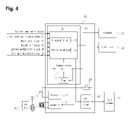
- FIG. 4 is a view showing the internal configuration of the controller in the structure of the automobile electronic key for security according to the present invention.
- the controller 400 in the structure of the automobile electronic key for security receives a plurality of signals from the outside, performs an operation for starting the engine of the automobile under a predetermined condition, authenticates the key fob 500 through communication with the key fob 500 and controls the car key 101 to be rotated when the key fob 500 passes authentication.
- the controller 400 includes a wireless transmitter 301 , a wireless receiver 302 , a micro control unit (MCU) 303 , a start relay 304 , and a coil antenna driver 305 .
- MCU micro control unit
- the wireless transmitter and the wireless receiver 301 and 302 transmit and receive data through wireless communication with the key fob 500 . That is, the wireless transmitter 301 transmits a radio signal to the key fob 500 to request the key fob 500 to send the ID thereof.
- the wireless receiver 302 receives the ID from the key fob 500 .
- the wireless transmitter 301 transmits an ID request signal to the key fob 500 through low frequency (LF) communication and the wireless receiver 303 receives the ID from the key fob 500 through radio frequency (RF) communication.
- LF low frequency
- RF radio frequency
- the MCU 303 includes an OR operation unit 31 that outputs a first control signal to the wireless transmitter 301 when a driver seat door closing signal S 1 or a brake pedal signal S 2 is on, an AND operation unit 32 that outputs a second control signal to the start relay 304 when the brake pedal signal S 2 , a gearshift parking (P) signal S 3 and an ignition switch start signal S 4 are simultaneously on, an authentication unit 33 for authenticating the key fob 500 using the ID received through the wireless receiver 302 , and a timer 35 for counting the time elapsed after the key fob 500 is authenticated by the authentication unit 33 .
- OR operation unit 31 that outputs a first control signal to the wireless transmitter 301 when a driver seat door closing signal S 1 or a brake pedal signal S 2 is on
- an AND operation unit 32 that outputs a second control signal to the start relay 304 when the brake pedal signal S 2 , a gearshift parking (P) signal S 3 and an ignition switch start signal S 4 are simultaneously on
- an authentication unit 33 for authenticating the key
- the wireless transmitter 301 drives a transmission antenna driver (not shown) included therein to perform wireless communication for requesting the key fob 500 to send the ID thereof when receiving the first control signal from the OR operation unit 31 . That is, the wireless transmitter 301 performs wireless communication with the key fob 500 to request the key fob 500 to transmit its ID only when one of the driver seat door closing signal S 1 and the brake pedal signal S 2 is input.
- the authentication unit 33 compares the ID of the key fob 500 received through the wireless receiver 302 with a previously stored ID and authenticates the key fob 500 .
- the timer 35 counts the time elapsed after the key fob 500 is authenticated by the authentication unit 33 .
- the actuator 320 is driven to move the locking member 310 such that the car key 101 becomes the unrotatable state. That is, the locking member 310 is moved again to switch the car key 101 to the unrotatable state to improve security when the engine is not started for a predetermined time even if the key fob passes authentication.
- the MCU 303 turns on the start relay 304 when the brake pedal signal S 2 , the gearshift P signal S 3 of an automatic transmission and the ignition switch start signal S 4 are on after the key fob 500 is authenticated.
- the brake pedal signal S 2 is output as an on signal according to internal signal processing when a driver steps on a brake pedal and output as an off signal according to internal signal processing when the driver does not step on the brake pedal.
- the gearshift P signal S 3 is output as an on signal when a gearshift of the automatic transmission is located in P position.
- P parking of the gearshift
- R reverse
- N neutral
- D drive
- the gearshift is placed to P and moved to R-N-D.
- the MCU 303 checks P state corresponding to top priority state.
- the gearshift P signal S 3 is output as an on signal.
- the start relay 304 can be configured of a switch.
- the switch opened in the initial stage is closed when the second control signal is received from the MCU 233 to supply current provided through an ignition switch to a start motor 330 for starting the engine.
- the MCU 303 drives the actuator 320 when the key fob 500 passes authentication.
- the actuator 320 controls the movement of the locking member 310 such that the car key 101 is switched to the rotatable state. If the key fob does not pass authentication, the actuator 320 is not driven. Accordingly, users other than the proper user cannot be authenticated, and thus the car key 101 is switched to the unrotatable state. This improves the security of the automobile.
- the switch 304 When a contact signal of the key fob 500 is input to the controller 400 , the switch 304 is on in order to drive the coil antenna driver 305 . Accordingly, the coil antenna driver 305 induces a voltage to a coil antenna 501 included in the electronic key structure to supply power to the battery included in the key fob 500 .
- the MCU 303 After the key fob 500 is authenticated, the MCU 303 turns on the start relay 304 when the brake pedal signal S 2 , the gearshift P signal S 3 of the automatic transmission and the ignition switch start signal S 4 are simultaneously on. Furthermore, the MCU 303 can turn on the start relay 304 even when the gearshift P signal S 3 , a parking brake switch signal S 5 and the ignition switch start signal S 4 are simultaneously on.
- FIG. 5 is a flow chart of the method for performing the function of the structure of the automobile electronic key for security according to the present invention.
- the controller 400 determines whether at least one of the driver seat door closing signal S 1 and the brake pedal signal S 2 is on in operation S 500 . It is determined that at least one of the driver seat door closing signal S 1 and the brake pedal signal S 2 is on in operation S 500 , the controller 400 requests the key fob 500 to send the ID thereof through wireless communication with the key fob 500 in operation S 502 . Then, the controller 400 receives the ID from the key fob 500 in operation S 504 . Subsequently, the controller 400 compares the received ID with an ID previously stored therein to authenticate the key fob 500 in operation S 506 .
- the controller 400 drives the actuator 320 in operation S 510 .
- the locking member 310 is moved according to the operation of the actuator 320 to switch the car key 101 to the rotatable state in operation S 512 . That is, according to the method for performing the function of the automobile electronic key structure according to the present invention, the car key 101 can be rotated only when the key fob passes authentication.
- the timer 35 operates to determine whether a predetermined time has elapsed after the key fob 500 is authenticated.
- the controller 400 determines whether all the brake pedal signal S 2 , the gearshift P signal S 3 and the ignition switch start signal S 4 are on before the predetermined time elapses in operation S 516 .
- the controller 400 When it is determined that all the three signals S 2 , S 3 and S 4 are on in operation S 516 , the controller 400 turns on the start relay 304 in operation S 518 . Then, the controller 400 transmits the ignition switch start signal S 4 for starting the engine from the ignition switch to the start motor 330 in operation S 520 .
- the start motor 330 starts the engine of the automobile according to the ignition switch start signal S 4 .
- the ignition switch start signal S 4 is used for the last step of four steps including a locking step, an accessory power supply step, a controller and driver on step and a starting step according to the rotation of the car key 101 .
- the controller 400 drives the actuator 320 in operation S 522 to move the locking member 310 such that the car key 101 is switched to the unrotatable state in operation S 524 .
- the car key can be rotated after the key fob is authenticated such that only a proper user who carries the key fob 500 can start the engine of the automobile.
Landscapes
- Engineering & Computer Science (AREA)
- Mechanical Engineering (AREA)
- Computer Networks & Wireless Communication (AREA)
- Physics & Mathematics (AREA)
- General Physics & Mathematics (AREA)
- Lock And Its Accessories (AREA)
Applications Claiming Priority (2)
| Application Number | Priority Date | Filing Date | Title |
|---|---|---|---|
| KR10-2007-0077105 | 2007-07-30 | ||
| KR1020070077105A KR100820859B1 (ko) | 2007-07-31 | 2007-07-31 | 차량 보안을 위한 전자 키 구조 |
Publications (2)
| Publication Number | Publication Date |
|---|---|
| US20090031767A1 US20090031767A1 (en) | 2009-02-05 |
| US8028552B2 true US8028552B2 (en) | 2011-10-04 |
Family
ID=39534330
Family Applications (1)
| Application Number | Title | Priority Date | Filing Date |
|---|---|---|---|
| US12/178,468 Expired - Fee Related US8028552B2 (en) | 2007-07-31 | 2008-07-23 | Structure of automobile electronic key for security and method for performing function thereof |
Country Status (6)
| Country | Link |
|---|---|
| US (1) | US8028552B2 (ko) |
| EP (1) | EP2020345B1 (ko) |
| JP (1) | JP2009035248A (ko) |
| KR (1) | KR100820859B1 (ko) |
| CN (1) | CN101359547A (ko) |
| AT (1) | ATE530396T1 (ko) |
Cited By (8)
| Publication number | Priority date | Publication date | Assignee | Title |
|---|---|---|---|---|
| US20090309696A1 (en) * | 2008-06-12 | 2009-12-17 | Kabushiki Kaisha Tokai Rika Denki Seisakusho | Vehicle function restriction system |
| US20100073130A1 (en) * | 2008-09-24 | 2010-03-25 | Kabushiki Kaisha Tokai Rika Denki Seisakusho | Key holding device for in-vehicle auxiliary key |
| US20110100075A1 (en) * | 2009-10-30 | 2011-05-05 | Hyundai Motor Company | Key interlock device for vehicle |
| US20110313595A1 (en) * | 2009-03-16 | 2011-12-22 | Toyota Jidosha Kabushiki Kaisha | Electronic key |
| WO2014042634A1 (en) * | 2012-09-13 | 2014-03-20 | International Truck Intellectual Property Company, Llc | Vehicle security lock out system |
| US20180178756A1 (en) * | 2016-12-22 | 2018-06-28 | Asahi Denso Co., Ltd. | Engine starting device |
| US20180178755A1 (en) * | 2016-12-22 | 2018-06-28 | Asahi Denso Co., Ltd. | Engine starting device |
| US10501050B2 (en) * | 2017-06-30 | 2019-12-10 | GM Global Technology Operations LLC | Vehicle ignition system |
Families Citing this family (15)
| Publication number | Priority date | Publication date | Assignee | Title |
|---|---|---|---|---|
| KR100820859B1 (ko) * | 2007-07-31 | 2008-04-11 | 양재우 | 차량 보안을 위한 전자 키 구조 |
| US8548645B2 (en) * | 2009-08-17 | 2013-10-01 | Donna Long | Two step keyless start system |
| US9133784B2 (en) * | 2011-02-01 | 2015-09-15 | Ford Global Technologies, Llc | Vehicle having key-based performance mode |
| JP5654421B2 (ja) * | 2011-07-07 | 2015-01-14 | オムロンオートモーティブエレクトロニクス株式会社 | 車両制御システム及び認証方法 |
| JP5662906B2 (ja) | 2011-08-25 | 2015-02-04 | オムロンオートモーティブエレクトロニクス株式会社 | 位置検知システム及び位置判定方法 |
| KR102180338B1 (ko) * | 2013-09-10 | 2020-11-19 | 현대모비스 주식회사 | Nfc를 이용한 포브 검색 장치 및 그 방법 |
| TWI538829B (zh) * | 2014-12-10 | 2016-06-21 | 鴻海精密工業股份有限公司 | 控制裝置及應用於該控制裝置的控制系統 |
| CN104538231A (zh) * | 2015-01-07 | 2015-04-22 | 浙江雷牌机件有限公司 | 一种无钥匙系统点火开关 |
| CN111032499B (zh) * | 2017-10-10 | 2022-02-01 | 本田技研工业株式会社 | 摩托车的智能钥匙单元的附接结构 |
| EP3707034A4 (en) * | 2017-11-07 | 2021-09-15 | Minda Corporation Limited | INTELLIGENT MULTIFUNCTIONAL IGNITION LOCK FOR VEHICLES |
| US10253528B1 (en) | 2018-02-21 | 2019-04-09 | Axtuator OY | Digital lock |
| US10641008B2 (en) | 2018-02-21 | 2020-05-05 | Axtuator OY | Electromagnetic actuator |
| KR102029659B1 (ko) * | 2018-05-16 | 2019-10-08 | 주식회사 서연전자 | 자동차의 도어 언락 제어장치 및 제어방법 |
| CN109035524A (zh) * | 2018-08-06 | 2018-12-18 | 常州市思索数码科技有限公司 | 锁具的开锁方法及离线和在线开锁系统 |
| CN108952333A (zh) * | 2018-08-06 | 2018-12-07 | 常州市思索数码科技有限公司 | 一种电子钥匙、门锁系统及电子钥匙开锁方法 |
Citations (23)
| Publication number | Priority date | Publication date | Assignee | Title |
|---|---|---|---|---|
| US6257031B1 (en) * | 1999-06-30 | 2001-07-10 | The Eastern Company | Ignition lock operable when key is removed |
| JP2001323698A (ja) | 2000-05-18 | 2001-11-22 | Nissan Motor Co Ltd | 車両用電子キー装置 |
| US6354117B1 (en) * | 1999-01-15 | 2002-03-12 | Valeo Securite Habitacle | Steering column anti-theft device for motor vehicle |
| US6382003B1 (en) * | 1999-06-11 | 2002-05-07 | Nissan Motor Co., Ltd. | Lock apparatus |
| US6389856B1 (en) * | 1999-06-11 | 2002-05-21 | Nissan Motor Co., Ltd. | Lock apparatus |
| JP2002242501A (ja) | 2001-02-16 | 2002-08-28 | Denso Corp | 自動車用無線施錠解錠装置 |
| US20030079509A1 (en) * | 2001-10-31 | 2003-05-01 | Isao Ochi | Steering lock apparatus |
| US20030231100A1 (en) * | 2002-06-18 | 2003-12-18 | Jin-Sang Chung | Vehicular burglarproof device |
| US20040227615A1 (en) * | 2003-05-16 | 2004-11-18 | Lear Corporation | Keyless smart start system |
| US20050012593A1 (en) * | 2003-04-11 | 2005-01-20 | Harrod Donald J. | Ignition apparatus and method |
| KR20060019343A (ko) | 2004-08-27 | 2006-03-03 | 한국델파이주식회사 | 통용 트랜스폰더를 이용한 전자키 셋 제어 장치 및 방법 |
| US7028515B2 (en) * | 2002-06-20 | 2006-04-18 | Hyundai Motor Company | Burglarproof locking device for a vehicle |
| US20060081023A1 (en) * | 2004-10-14 | 2006-04-20 | Mazda Motor Corporation | Steering lock apparatus |
| US20060220458A1 (en) * | 2005-04-05 | 2006-10-05 | Feldman Mark G | Keyless ignition module for an automotive vehicle |
| US20060225985A1 (en) * | 2005-03-30 | 2006-10-12 | Dimig Steven J | Residual magnetic devices and methods |
| US20070131004A1 (en) * | 2005-12-09 | 2007-06-14 | Jin-Sang Chung | Key interlock device for steering column lock device |
| US7302817B2 (en) * | 2002-05-29 | 2007-12-04 | Kabushiki Kaisha Tokai Rika Denki Seisakusho | Apparatus for restricting activation of engine starting system |
| US20070284943A1 (en) * | 2006-03-20 | 2007-12-13 | John Meeks | RF-immobilizer and contactless ignition for a motor vehicle |
| US20080178643A1 (en) * | 2007-01-30 | 2008-07-31 | Tokai Rika Co., Ltd | Assembling method of electric steering lock device |
| US20080236216A1 (en) * | 2007-03-27 | 2008-10-02 | Honda Motor Co., Ltd. | Steering means locking apparatus |
| US20090031767A1 (en) * | 2007-07-31 | 2009-02-05 | Jae Woo Yang | Structure of automobile electronic key for security and method for performing function thereof |
| US20090033150A1 (en) * | 2007-07-30 | 2009-02-05 | Jae Pyung Ko | Apparatus and method for starting engine of automobile using start-button |
| US7591158B2 (en) * | 2003-10-03 | 2009-09-22 | Honda Motor Co., Ltd. | Vehicle locking apparatus |
Family Cites Families (8)
| Publication number | Priority date | Publication date | Assignee | Title |
|---|---|---|---|---|
| DE3314072C2 (de) * | 1983-04-19 | 1986-01-23 | Daimler-Benz Ag, 7000 Stuttgart | Schloßsystem zur mechanischen und elektronischen Steuerung von Verriegelungen in einem Kraftfahrzeug |
| JPS62128857A (ja) * | 1985-11-29 | 1987-06-11 | Nissan Motor Co Ltd | 車両用錠装置 |
| US5255547A (en) * | 1992-08-19 | 1993-10-26 | General Motors Corporation | Ignition lock with dual unlocking modes |
| DE4421496B4 (de) * | 1993-10-01 | 2006-09-07 | Marquardt Gmbh | Elektronisches Türschließsystem an einem Kraftfahrzeug |
| DE4402853C1 (de) * | 1994-01-31 | 1994-11-24 | Daimler Benz Ag | Handsender zur Fernbedienung verschiedener Fahrzeugsysteme |
| JP3545647B2 (ja) * | 1999-06-11 | 2004-07-21 | 株式会社アルファ | 電子キイ構造 |
| JP3988540B2 (ja) * | 2002-01-11 | 2007-10-10 | 株式会社デンソー | 車両用エンジン制御装置、車両用イグニッションスイッチ装置、車両用エンジン制御システム、携帯機 |
| US20050012594A1 (en) * | 2003-07-17 | 2005-01-20 | Youngtack Shim | Key assemblies and methods |
-
2007
- 2007-07-31 KR KR1020070077105A patent/KR100820859B1/ko not_active IP Right Cessation
-
2008
- 2008-07-18 JP JP2008187422A patent/JP2009035248A/ja active Pending
- 2008-07-18 EP EP20080013039 patent/EP2020345B1/en not_active Not-in-force
- 2008-07-18 AT AT08013039T patent/ATE530396T1/de not_active IP Right Cessation
- 2008-07-23 US US12/178,468 patent/US8028552B2/en not_active Expired - Fee Related
- 2008-07-30 CN CNA2008101351141A patent/CN101359547A/zh active Pending
Patent Citations (24)
| Publication number | Priority date | Publication date | Assignee | Title |
|---|---|---|---|---|
| US6354117B1 (en) * | 1999-01-15 | 2002-03-12 | Valeo Securite Habitacle | Steering column anti-theft device for motor vehicle |
| US6382003B1 (en) * | 1999-06-11 | 2002-05-07 | Nissan Motor Co., Ltd. | Lock apparatus |
| US6389856B1 (en) * | 1999-06-11 | 2002-05-21 | Nissan Motor Co., Ltd. | Lock apparatus |
| US6257031B1 (en) * | 1999-06-30 | 2001-07-10 | The Eastern Company | Ignition lock operable when key is removed |
| JP2001323698A (ja) | 2000-05-18 | 2001-11-22 | Nissan Motor Co Ltd | 車両用電子キー装置 |
| JP2002242501A (ja) | 2001-02-16 | 2002-08-28 | Denso Corp | 自動車用無線施錠解錠装置 |
| US20030079509A1 (en) * | 2001-10-31 | 2003-05-01 | Isao Ochi | Steering lock apparatus |
| US6786069B2 (en) * | 2001-10-31 | 2004-09-07 | U-Shin Ltd. | Steering lock apparatus |
| US7302817B2 (en) * | 2002-05-29 | 2007-12-04 | Kabushiki Kaisha Tokai Rika Denki Seisakusho | Apparatus for restricting activation of engine starting system |
| US20030231100A1 (en) * | 2002-06-18 | 2003-12-18 | Jin-Sang Chung | Vehicular burglarproof device |
| US7028515B2 (en) * | 2002-06-20 | 2006-04-18 | Hyundai Motor Company | Burglarproof locking device for a vehicle |
| US20050012593A1 (en) * | 2003-04-11 | 2005-01-20 | Harrod Donald J. | Ignition apparatus and method |
| US20040227615A1 (en) * | 2003-05-16 | 2004-11-18 | Lear Corporation | Keyless smart start system |
| US7591158B2 (en) * | 2003-10-03 | 2009-09-22 | Honda Motor Co., Ltd. | Vehicle locking apparatus |
| KR20060019343A (ko) | 2004-08-27 | 2006-03-03 | 한국델파이주식회사 | 통용 트랜스폰더를 이용한 전자키 셋 제어 장치 및 방법 |
| US20060081023A1 (en) * | 2004-10-14 | 2006-04-20 | Mazda Motor Corporation | Steering lock apparatus |
| US20060225985A1 (en) * | 2005-03-30 | 2006-10-12 | Dimig Steven J | Residual magnetic devices and methods |
| US20060220458A1 (en) * | 2005-04-05 | 2006-10-05 | Feldman Mark G | Keyless ignition module for an automotive vehicle |
| US20070131004A1 (en) * | 2005-12-09 | 2007-06-14 | Jin-Sang Chung | Key interlock device for steering column lock device |
| US20070284943A1 (en) * | 2006-03-20 | 2007-12-13 | John Meeks | RF-immobilizer and contactless ignition for a motor vehicle |
| US20080178643A1 (en) * | 2007-01-30 | 2008-07-31 | Tokai Rika Co., Ltd | Assembling method of electric steering lock device |
| US20080236216A1 (en) * | 2007-03-27 | 2008-10-02 | Honda Motor Co., Ltd. | Steering means locking apparatus |
| US20090033150A1 (en) * | 2007-07-30 | 2009-02-05 | Jae Pyung Ko | Apparatus and method for starting engine of automobile using start-button |
| US20090031767A1 (en) * | 2007-07-31 | 2009-02-05 | Jae Woo Yang | Structure of automobile electronic key for security and method for performing function thereof |
Cited By (12)
| Publication number | Priority date | Publication date | Assignee | Title |
|---|---|---|---|---|
| US20090309696A1 (en) * | 2008-06-12 | 2009-12-17 | Kabushiki Kaisha Tokai Rika Denki Seisakusho | Vehicle function restriction system |
| US8487740B2 (en) * | 2008-06-12 | 2013-07-16 | Kabushiki Kaisha Tokai Rika Denki Seisakusho | Vehicle function restriction system |
| US20100073130A1 (en) * | 2008-09-24 | 2010-03-25 | Kabushiki Kaisha Tokai Rika Denki Seisakusho | Key holding device for in-vehicle auxiliary key |
| US8511121B2 (en) * | 2008-09-24 | 2013-08-20 | Kabushiki Kaisha Tokai Rika Denki Seisakusho | Key holding device for in-vehicle auxiliary key |
| US20110313595A1 (en) * | 2009-03-16 | 2011-12-22 | Toyota Jidosha Kabushiki Kaisha | Electronic key |
| US20110100075A1 (en) * | 2009-10-30 | 2011-05-05 | Hyundai Motor Company | Key interlock device for vehicle |
| WO2014042634A1 (en) * | 2012-09-13 | 2014-03-20 | International Truck Intellectual Property Company, Llc | Vehicle security lock out system |
| US20180178756A1 (en) * | 2016-12-22 | 2018-06-28 | Asahi Denso Co., Ltd. | Engine starting device |
| US20180178755A1 (en) * | 2016-12-22 | 2018-06-28 | Asahi Denso Co., Ltd. | Engine starting device |
| US10576928B2 (en) * | 2016-12-22 | 2020-03-03 | Asahi Denso Co., Ltd. | Engine starting device |
| US11148637B2 (en) * | 2016-12-22 | 2021-10-19 | Asahi Denso Co., Ltd. | Engine starting device |
| US10501050B2 (en) * | 2017-06-30 | 2019-12-10 | GM Global Technology Operations LLC | Vehicle ignition system |
Also Published As
| Publication number | Publication date |
|---|---|
| JP2009035248A (ja) | 2009-02-19 |
| US20090031767A1 (en) | 2009-02-05 |
| CN101359547A (zh) | 2009-02-04 |
| ATE530396T1 (de) | 2011-11-15 |
| EP2020345B1 (en) | 2011-10-26 |
| EP2020345A3 (en) | 2011-03-09 |
| EP2020345A2 (en) | 2009-02-04 |
| KR100820859B1 (ko) | 2008-04-11 |
Similar Documents
| Publication | Publication Date | Title |
|---|---|---|
| US8028552B2 (en) | Structure of automobile electronic key for security and method for performing function thereof | |
| US20090033150A1 (en) | Apparatus and method for starting engine of automobile using start-button | |
| KR100943928B1 (ko) | 엔진 스위치 장치 | |
| US9156437B2 (en) | Remote starting system for vehicle and control method for the same | |
| JP4167320B2 (ja) | 車両用ワイヤレス制御装置およびその携帯機 | |
| CN201309468Y (zh) | 汽车启动系统 | |
| US8408031B2 (en) | Ignition switch operation restricting device | |
| EP2251837A2 (en) | Portable device and remote control system | |
| US20140200757A1 (en) | Onboard system, electronic key system, and control unit | |
| US20090153294A1 (en) | Mechanical key code verification system | |
| JP2012250584A (ja) | 始動制御装置 | |
| US20110208413A1 (en) | Apparatus and method for starting automobile using start-button | |
| JP2006137338A (ja) | エンジン始動システム | |
| JP3799961B2 (ja) | 車両用電子キー装置 | |
| JP2008050943A (ja) | 車両用ワイヤレス制御装置 | |
| KR100820318B1 (ko) | 자동차의 이그니션 노브 록 장치 및 그 록킹방법 | |
| KR100856809B1 (ko) | 무선제어형 이그니션 노브 록 장치 및 그의 록킹방법 | |
| KR100856580B1 (ko) | 전동제어형 자동차 이그니션 노브 록 장치 및 그의록킹방법 | |
| KR100820858B1 (ko) | 차량 보안을 위한 시동 키 구조 | |
| JP5507342B2 (ja) | イグニッションスイッチの操作規制装置 | |
| JP6629680B2 (ja) | 車両制御システム、車両制御装置、携帯機 | |
| JPH10153025A (ja) | 車両用ドアロックシステム | |
| JP5172623B2 (ja) | キー収容装置 | |
| JP3908089B2 (ja) | エンジン始動システムの操作規制装置 | |
| JP7060058B2 (ja) | キーシステムを用いた車載機器の制御方法およびキーシステム |
Legal Events
| Date | Code | Title | Description |
|---|---|---|---|
| AS | Assignment |
Owner name: YANG, JAE WOO, KOREA, REPUBLIC OF Free format text: ASSIGNMENT OF ASSIGNORS INTEREST;ASSIGNORS:KO, JAE PYUNG;KIM, YOUNG TAK;LEE, KYOUNG MOON;AND OTHERS;REEL/FRAME:021282/0058 Effective date: 20080717 |
|
| AS | Assignment |
Owner name: DONG-A UNIVERSITY RESEARCH FOUNDATION FOR INDUSTRY Free format text: ASSIGNMENT OF ASSIGNORS INTEREST;ASSIGNOR:YANG, JAE WOO;REEL/FRAME:023329/0039 Effective date: 20090915 |
|
| STCF | Information on status: patent grant |
Free format text: PATENTED CASE |
|
| FPAY | Fee payment |
Year of fee payment: 4 |
|
| FEPP | Fee payment procedure |
Free format text: MAINTENANCE FEE REMINDER MAILED (ORIGINAL EVENT CODE: REM.); ENTITY STATUS OF PATENT OWNER: SMALL ENTITY |
|
| LAPS | Lapse for failure to pay maintenance fees |
Free format text: PATENT EXPIRED FOR FAILURE TO PAY MAINTENANCE FEES (ORIGINAL EVENT CODE: EXP.); ENTITY STATUS OF PATENT OWNER: SMALL ENTITY |
|
| STCH | Information on status: patent discontinuation |
Free format text: PATENT EXPIRED DUE TO NONPAYMENT OF MAINTENANCE FEES UNDER 37 CFR 1.362 |
|
| FP | Lapsed due to failure to pay maintenance fee |
Effective date: 20191004 |