US8019460B2 - Numerical controller of machine tool - Google Patents
Numerical controller of machine tool Download PDFInfo
- Publication number
- US8019460B2 US8019460B2 US12/207,122 US20712208A US8019460B2 US 8019460 B2 US8019460 B2 US 8019460B2 US 20712208 A US20712208 A US 20712208A US 8019460 B2 US8019460 B2 US 8019460B2
- Authority
- US
- United States
- Prior art keywords
- retracting
- unit
- movable unit
- interference
- shape data
- Prior art date
- Legal status (The legal status is an assumption and is not a legal conclusion. Google has not performed a legal analysis and makes no representation as to the accuracy of the status listed.)
- Active, expires
Links
Images


Classifications
-
- G—PHYSICS
- G05—CONTROLLING; REGULATING
- G05B—CONTROL OR REGULATING SYSTEMS IN GENERAL; FUNCTIONAL ELEMENTS OF SUCH SYSTEMS; MONITORING OR TESTING ARRANGEMENTS FOR SUCH SYSTEMS OR ELEMENTS
- G05B19/00—Programme-control systems
- G05B19/02—Programme-control systems electric
- G05B19/18—Numerical control [NC], i.e. automatically operating machines, in particular machine tools, e.g. in a manufacturing environment, so as to execute positioning, movement or co-ordinated operations by means of programme data in numerical form
- G05B19/4097—Numerical control [NC], i.e. automatically operating machines, in particular machine tools, e.g. in a manufacturing environment, so as to execute positioning, movement or co-ordinated operations by means of programme data in numerical form characterised by using design data to control NC machines, e.g. CAD/CAM
-
- G—PHYSICS
- G05—CONTROLLING; REGULATING
- G05B—CONTROL OR REGULATING SYSTEMS IN GENERAL; FUNCTIONAL ELEMENTS OF SUCH SYSTEMS; MONITORING OR TESTING ARRANGEMENTS FOR SUCH SYSTEMS OR ELEMENTS
- G05B2219/00—Program-control systems
- G05B2219/30—Nc systems
- G05B2219/35—Nc in input of data, input till input file format
- G05B2219/35316—Interference checking between tool, machine, part, chuck, machining range
Definitions
- the present invention relates to a numerical controller which controls a shaft movement of a movable unit of a machine tool and which avoids a mechanical collision between the movable unit and an interfering structure in the event of a power outage.
- FIG. 5 is a block diagram of such a control technique.
- a machining program is input from a program-inputting unit 1 and is sent to a program-analyzing unit 2 .
- the program-analyzing unit 2 generates data of a feed direction and sends the data to a function-generating unit 3 as an instruction.
- the function-generating unit 3 Upon receiving the instruction, the function-generating unit 3 generates a function to start calculation of the function-generating position for each shaft-controlling period and decelerate and stop the movable unit to a target position, in order to control the shaft movement of the movable unit of the machine tool.
- the function-generating position reference is made to feed speed data which are set and stored in advance by a feed speed data storage unit (not shown) as a unit amount of acceleration or deceleration for each control shaft and each control period, and the function generation position is calculated such that the shaft of the movable body moves at a predetermined acceleration and a predetermined speed.
- the calculated function generation position is sent to a servo drive unit 5 for each shaft-controlling period.
- a three-phase AC power supply is connected as an input power supply, and a smoothing capacitor (not shown) is connected and built into a direct current (DC) side power supply terminal portion.
- the servo drive unit 5 is connected to the DC-side power supply terminal.
- a plurality of servo drive units 5 may be connected to the DC-side power supply terminal of the DC power supply unit 4 .
- servo drive unit 5 supply of the DC power from the DC power supply unit 4 is received, and a current is supplied to a servo motor 6 to drive the movable unit of the machine tool based on the function generation position received from the function-generating unit 3 .
- a regeneration energy generated by the deceleration is returned to the AC power supply through the servo drive unit 5 and the DC power supply unit 4 .
- FIG. 6 shows a machining operation performed by a machining center, and a workpiece W is machined by a tool T moving in a direction of a cutting instruction vector Vc(t) in a Z negative direction while the tool T rotates.
- the supply of the three-phase AC power to the DC power supply unit is stopped, resulting in inability to generate the DC power supply to the servo drive unit 5 , and, consequently, stoppage of the supply of current from the servo drive unit 5 to the servo motor 6 .
- the spindle motor which rotates and drives the tool T and the servo motor 6 which drives the feed shaft are decelerated and stopped because the power from the servo drive unit 5 is stopped.
- the function generation is stopped in the middle of the function generation. Because of this, for example, if the cutting process has been applied while synchronizing the X axis and the Y axis, the synchronization of the X axis and the Y axis is disturbed by the stoppage of the function generation, and the tool is decelerated and stopped independently for each axis. More specifically, the tool T decelerates and stops while the rotating tool T is engaged in the workpiece W, and there arises a problem that the workpiece is wasted and the tool is damaged at the same time.
- JP Hei 8-227307 A discloses a method of retracting the tool in a direction away from an interference position of the tool and the workpiece. In this retracting method, however, because the retracting direction is uniform, there still remains the problem that, if there is an interfering structure in the retracting direction, the movable unit interferes with the interfering structure.
- the present invention has been conceived in view of the above-described circumstances, and an advantage of the present invention is provision of a numerical controller which enables fine control of shaft movement upon occurrence of a power outage so that collision between the workpiece and the movable unit such as the tool can be avoided safely, reliably, and precisely.
- Documents describing the related art include JP Hei 8-227307 A and JP 2002-182714 A.
- a numerical controller of a machine tool which controls movement of a movable unit of a machine tool
- the numerical controller comprising a shape data storage unit which stores movable unit shape data which indicate a position and a shape of the movable unit and interfering structure shape data which indicate a position and a shape of an interfering structure with respect to the movable unit; a retracting direction determining unit which determines, on the basis of a current position and a movement control direction of the movable unit, a retracting direction of the movable unit during power outage (hereinafter called a “retracting direction of the movable unit for power outage”); an interference determining unit which determines, on the basis of the movable unit shape data and the interfering structure shape data, presence or absence of interference between the movable unit and the interfering structure when the movable unit is moved in the retracting direction for power outage which is determined by the retracting direction determining unit; a retracting position
- the retracting direction determining unit determines, on a plane which forms a predetermined angle with the movement control direction of the movable unit, a plurality of retracting vectors having their origin at a position of the movable unit; calculates, on the basis of the movable unit shape data and the interfering structure shape data, a relative distance between the movable unit and the interfering structure for each of directions of the retracting vectors; and determines, as the retracting direction for power outage, a direction of a retracting vector selected from among the plurality of retracting vectors on the basis of the relative distance.
- the retracting direction determining unit determines, on a plane which forms a predetermined angle with the movement control direction of the movable unit, a plurality of retracting vectors having their origin at a position of the movable unit; calculates, for each of the retracting vectors, a change, with respect to time during retracting of a movable unit, of energy in which a kinetic energy of the movable unit and a potential energy of the movable unit are added; and determines, as the retracting direction for power outage, a direction of a retracting vector selected from among the plurality of retracting vectors on the basis of the change with respect to time during retracting.
- the interference determining unit comprises an interference checking position calculating unit which calculates, as an interference checking position, a position in which an amount of retracting for checking is added to the current position of the movable unit in the retracting direction for power outage which is determined by the retracting direction determining unit; and an interference confirming unit which checks, on the basis of the movable unit shape data and the interfering structure shape data, presence or absence of an overlap between the movable unit and the interfering structure when the movable unit is moved to the interference checking position, determines that there is an interference when there is an overlap, and determines that there is no interference when there is no overlap, and the retracting position calculating unit determines the retracting position on the basis of the retracting direction determined by the retracting direction determining unit and the amount of retracting for checking which is determined by the interference confirming unit confirming that there is no interference.
- a numerical controller which can safely, reliably, and precisely avoid collision of the movable unit and the interfering structure even in the event of power outage.
- FIG. 1 is a block diagram showing a configuration of a numerical controller of a preferred embodiment according to the present invention
- FIG. 2 is a flowchart showing an example of a control method in a preferred embodiment according to the present invention
- FIG. 3 is a diagram for explaining a specific operation in a machining center in a preferred embodiment according to the present invention.
- FIG. 4 is a diagram for explaining a specific operation performed on a lathe in a preferred embodiment according to the present invention.
- FIG. 5 is a block diagram of a controller
- FIG. 6 is a diagram for explaining a specific operation performed in a machining center.
- FIG. 1 is a block diagram showing an example structure of a numerical controller according to a preferred embodiment of the present invention, having a collision avoiding function when power outage occurs.
- Reference numerals 1 , 2 , 4 , 5 , and 6 represent structures identical to those of FIG. 5 , and will not be described again.
- a shape data storage unit 7 registers and stores, in addition to shape data which indicate a position and a shape of a movable unit of a machine tool such as a tool, shape data which indicate a position and a shape of a workpiece, a jig, and a mechanical interfering structure which may interfere when the shaft of the movable unit of the machine tool is moved.
- the movable unit moving by the shaft movement and the interfering structure which may interfere due to the movement differ depending on the structure of the machine tool, and are not particularly limited to those described in the following description.
- a retracting direction determining unit 8 In order to determine the retracting direction on the basis of the shape data received from the shape data storage unit 7 , a retracting direction determining unit 8 successively calculates a vector, from among cross points between the retracting vectors and the interfering structure on a plane perpendicular to the movement direction of the feed shaft for which an instruction is received from the program analyzing unit 2 , in which vector the relative distance from the current position is the longest. The interference distance with the interfering structure in each of the directions of the vectors is determined, and the vector having the longest distance is ultimately determined as the retracting direction.
- an interference checking position calculating unit 9 successively calculates, as an interference checking position, a position moved from the current position of the movable unit by a desired amount of retracting according to the determined retracting direction.
- An interference confirming unit 10 checks, on the basis of the shape data of the movable unit and the shape data of the interfering structure, presence or absence of an overlap within, for example, a three-dimensional space between the movable unit and the interfering structure when the movable unit is successively, virtually moved to the interference checking position; confirms that there is an interference when there is an overlap; and confirms that there is no interference when there is no overlap.
- the interference checking position calculating unit 9 again calculates the interference checking position.
- a retracting position calculating unit 11 calculates a retracting position on the basis of the retracting direction determined by the retracting direction determining unit 8 and the amount of retracting which is determined by the interference confirming unit 10 such that there is no interference.
- the calculated retracting position is sent to the function-generating unit 3 .
- a power outage detecting unit 12 monitors for power outage on a side of the AC power supply of the DC power supply unit 4 ; for example, the three-phase AC power supply, and, upon detection of power outage of the AC power supply, the power outage detecting unit 12 transmits a power outage detecting signal to the DC power supply unit 4 , and the DC power supply unit 4 stops regeneration of the power supply so that the accumulated power can be used for driving the feed shaft.
- the power outage detecting unit 12 sends a power outage detecting signal also to the function-generating unit 3 .
- the function-generating unit 3 Upon receiving the power outage detecting signal, the function-generating unit 3 generates a function on the basis of the retracting position sent from the retracting position calculating unit 11 , and sends the function generation result to the servo drive unit 5 .
- the servo drive unit 5 sends a desired current instruction to the servo motor 6 based on the sent generated function, and the servo motor 6 retracts the movable unit of the machine tool according to the current instruction.
- FIG. 3 illustrates machining performed by a machining center in which a tool T machines a workpiece W in a direction of a cutting instruction vector Vc (t) in a negative Z direction while the tool T rotates.
- a perpendicular plane in FIG. 3 , an XZ plane Pxz which passes through the current position P(t) and which is perpendicular to the instruction vector Vc(t) is considered.
- Retracting vectors VAn(t) having their origin at the current position P(t) are defined on the perpendicular plane.
- vectors in 8 directions are considered as the retracting vectors VAn(t) (The number n is an integer from 0 to 7.).
- the maximum value of the number n does not need to be 7, and may be an arbitrary integer greater than or equal to 1.
- the shape data of the tool T and the shape data of the interfering structure, etc. are used.
- the relationship between the tool T and the workpiece W on the XZ plane Pxz is determined as an interference when the tool T is moved in directions of retracting vectors VA 1 ( t )-VA 6 ( t ), because the relationship is contact; that is, the relative distance is 0, for a line segment P 1 ( t )P 2 ( t )P 6 ( t ). Therefore, the retracting direction is VA 0 ( t ) or VA 7 ( t ).
- the interference distance with other interfering structures (for example, structures used for setup) in each vector direction of the retracting vectors VA 0 ( t ) and VA 7 ( t ) is determined, and a vector having the longest relative distance is ultimately determined as the retracting direction.
- the retracting direction can be determined by generating the retracting vector on a plane which is parallel to the instruction direction Vc(t).
- the direction of the plane on which the retracting vectors are to be generated may be defined according to the contact status of the tool T and the workpiece W so that the retracting direction can be determined.
- an energy difference (kinetic energy+potential energy) between instruction of the retracting vectors during current timing tk and the instruction vector of the previous timing; that is, at (tk ⁇ 1), may be determined from the following Equation 1.
- a vector in which the change with respect to time of the energy ⁇ E is the smallest is ultimately determined as the retracting vector.
- ⁇ E ⁇ 1 ⁇ 2 ⁇ Vn ( tk ) ⁇ 2 ⁇ 1 ⁇ 2 ⁇ V ⁇ 2 ⁇ + ⁇ P ( tk ) ⁇ P ( tk ⁇ 1) ⁇ G (Equation 1)
- Vn(t) represents the instruction vector
- V represents a current speed
- P(t) represents the current position
- G represents a gravity vector.
- a position moved from the current position P(t) by a desired amount of retracting in the retracting vector direction determined as described above is set as an interference checking position.
- This check is based on the shape data of the movable unit including the tool T and the shape data of the interfering structure.
- the retracting direction and the retracting amount are determined.
- the function-generating unit 3 receives the power outage detecting signal from the power outage detecting unit 12 , the function-generating unit 3 generates a function according to the shaft movement stopping position calculated on the basis of the retracting direction and the retracting amount, to retract the tool T from the workpiece W.
- the electric energy accumulated in the smoothing capacitor of the DC power supply unit 4 may be used.
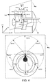
- FIG. 4 is a cross sectional diagram showing machining performed by a lathe.
- a tool T is inserted to the inner side of the workpiece W while the workpiece W is rotated, and the tool T machines in the direction of the cutting instruction vector Vc(t) in the positive X direction.
- a perpendicular plane in FIG. 4 , XY plane Pxy
- Retracting vectors VAn(t) having their origin at the current position P(t) are defined on the perpendicular plane.
- vectors in 8 directions are defined with the number n(The number n is an integer from 0 to 7.) as the retracting vectors VAn(t).
- vectors VA 0 ( t ), VA 1 ( t ), VA 2 ( t ), VA 3 ( t ), VA 4 ( t ), VA 5 ( t ), VA 6 ( t ), and VA 7 ( t ), which divide a circle centered at the current position P(t) into 2 ⁇ /8 [rad] (The number N in FIG. 4 is equal to the maximum value of the number n+1.), are defined.
- the maximum value of the number n does not need to be 7, and may be an arbitrary integer greater than or equal to 1.
- a vector in which the relative distance from the current position P(t) is the longest is successively calculated from among crossing points between the retracting vectors VAn(t) on the plane (in FIG. 4 , XY plane Pxy) perpendicular to the direction of the feed shaft received from the program-analyzing unit 2 ; that is, the instruction vector Vc(t) and the workpiece W which is an interfering structure for the tool T.
- the shape data of the tool T and the shape data of the interfering structure, etc. are used.
- the relationship between the tool T and the workpiece W centered at the current position P(t) is contact; that is, the relative position is 0 at the point P(t), and the movements to the directions of the retracting vectors VA 0 ( t ), VA 1 ( t ), VA 2 ( t ), VA 6 ( t ), and VA 7 ( t ) are determined as interference. Therefore, possible retracting directions are VA 3 ( t ), VA 4 ( t ), and VA 5 ( t ). If the interference distances with the other interfering structures (the workpiece W in the case depicted in FIG.
- the interference distances between the retracting vectors VA 3 ( t ), VA 4 ( t ), and VA 5 ( t ) and the workpiece W are line segments P(t)P 3 ( t ), P(t)P 4 ( t ), and P(t)P 5 ( t ), respectively, and, thus, the vector VA 4 ( t ) in which the distance is the longest is determined as the ultimate retracting direction.
- the retracting direction can be determined by generating a retracting vector on a plane parallel to the instruction direction Vc(t).
- the direction of the plane on which the retracting vector is to be generated may be determined based on the contacting status of the tool T and the workpiece W, so that the retracting direction can be determined.
- a position moved from the current position P(t) in the direction of the retracting vector VA 4 ( t ) determined as described above by a desired retracting amount is set as an interference checking position. Then, an overlap in, for example, the three-dimensional space, of the movable unit including the tool T and the interfering structure (in the case depicted in FIG. 4 , the workpiece W and the interfering structure present outside of the workpiece W) is checked for a case where the movable unit including the tool T (the overall movable unit is not shown) is virtually moved to the interference checking position. This check is executed based on the shape data of the movable unit including the tool T and the shape data of the interfering structure.
- the retracting direction and the retracting amount are determined as described above.
- the function-generating unit 3 receives the power outage detecting signal from the power outage detecting unit 12 , the function-generating unit 3 generates a function according to the stopping position of the shaft movement calculated based on the retracting direction and the retracting amount, and the tool T is retracted from the workpiece W.
- the electric energy accumulated in the smoothing capacitor of the DC power supply unit 4 may be used.
- step S 1 in order to determine the retracting direction using the shape data of the tool T and the shape data of the workpiece W, a vector in which the relative distance from the current position Pc is the longest is successively calculated from among crossing points between retracting vectors VAn(t) on a plane perpendicular to the direction of the feed shaft received from the program-analyzing unit 2 ; that is, the instruction vector Vc(t) and the workpiece W which is the interfering structure.
- the interference distance with the interfering structure in each of the directions of the vectors is determined, and a vector with the longest distance is determined ultimately as the retracting direction.
- step S 2 a position moved from the current position P(t) in the retracting vector direction determined as described above by a desired amount of retracting is set as the interference checking position.
- step S 3 there is checked an overlap in, for example, the three-dimensional space, between the movable unit including the tool T and the interfering structure when the shape data of the movable unit including the tool T is virtually moved to the interfering checking position. This check is executed based on the shape data of the movable unit and the shape data of the interfering structure received from the shape data storage unit 7 . When there is no overlap between the movable unit moved to the interference checking position and the interfering structure, it is confirmed that there is no interference, and the retracting amount is determined.
- step S 4 a retracting position considering the present position P(t) and the determined retracting amount is calculated based on the result of step S 3 .
- the retracting position calculating unit 11 sends the calculated retracting position to the function-generating unit 3 .
- step S 5 if the power outage detecting unit 12 does not detect the power outage; that is, during a normal time, the process returns to step S 1 .
- step S 6 the power supply regeneration from the side of the DC power supply to the side of the AC power supply is stopped by the power outage detecting signal sent from the power outage detecting unit 12 , and the electric power is accumulated on the DC bus line of the DC power supply unit 4 .
- step S 7 the servo drive unit 5 supplies power to the servo motor 6 using the power accumulated in the DC power supply unit 4 , and the movable unit is retracted.
- interference check using the shape data is constantly executed, and the function can be generated based on the result of the interference check to retract the movable unit to a non-interfering direction. Because of this, it is possible to safely, reliably, and precisely avoid collision between the movable unit and the interfering structure even in the event of power outage.
Landscapes
- Engineering & Computer Science (AREA)
- Human Computer Interaction (AREA)
- Manufacturing & Machinery (AREA)
- Physics & Mathematics (AREA)
- General Physics & Mathematics (AREA)
- Automation & Control Theory (AREA)
- Numerical Control (AREA)
- Automatic Control Of Machine Tools (AREA)
- Automatic Tool Replacement In Machine Tools (AREA)
Applications Claiming Priority (2)
| Application Number | Priority Date | Filing Date | Title |
|---|---|---|---|
| JP2007243291A JP4838782B2 (ja) | 2007-09-20 | 2007-09-20 | 工作機械数値制御装置 |
| JP2007-243291 | 2007-09-20 |
Publications (2)
| Publication Number | Publication Date |
|---|---|
| US20090082900A1 US20090082900A1 (en) | 2009-03-26 |
| US8019460B2 true US8019460B2 (en) | 2011-09-13 |
Family
ID=40435662
Family Applications (1)
| Application Number | Title | Priority Date | Filing Date |
|---|---|---|---|
| US12/207,122 Active 2030-04-07 US8019460B2 (en) | 2007-09-20 | 2008-09-09 | Numerical controller of machine tool |
Country Status (5)
| Country | Link |
|---|---|
| US (1) | US8019460B2 (de) |
| JP (1) | JP4838782B2 (de) |
| CN (1) | CN101393448B (de) |
| DE (1) | DE102008046830B4 (de) |
| IT (1) | IT1392532B1 (de) |
Cited By (7)
| Publication number | Priority date | Publication date | Assignee | Title |
|---|---|---|---|---|
| US20130214708A1 (en) * | 2012-02-20 | 2013-08-22 | Kabushiki Kaisha Yaskawa Denki | Power regeneration device and power conversion device |
| US20130342149A1 (en) * | 2012-06-25 | 2013-12-26 | Fanuc Corporation | Motor control device that decreases power consumed by control power source when power fails |
| US20130342013A1 (en) * | 2012-06-25 | 2013-12-26 | Fanuc Corporation | Motor control device that decreases power consumed by control power source when power fails |
| US20140292232A1 (en) * | 2013-03-29 | 2014-10-02 | Fanuc Corporation | Motor controller for synchronously controlling multiple motors |
| US20150145465A1 (en) * | 2013-11-26 | 2015-05-28 | Fanuc Corporation | Servo controller having function for reducing dropping when braking |
| US20150355627A1 (en) * | 2014-06-10 | 2015-12-10 | Fanuc Corporation | Motor control system and motor control method which protect tool and workpiece at time of power outage |
| US10350720B2 (en) * | 2016-04-20 | 2019-07-16 | Makita Corporation | Electric working machine |
Families Citing this family (12)
| Publication number | Priority date | Publication date | Assignee | Title |
|---|---|---|---|---|
| JP5395720B2 (ja) * | 2010-03-29 | 2014-01-22 | オークマ株式会社 | 停電時制御装置 |
| CN102298356B (zh) * | 2011-06-09 | 2013-04-17 | 四川普什宁江机床有限公司 | 数控滚齿机床刀具破损区域自动避让的窜刀方法 |
| US9046888B2 (en) * | 2012-06-27 | 2015-06-02 | Mitsubishi Electric Research Laboratories, Inc. | Method and system for detouring around features cut from sheet materials with a laser cutter according to a pattern |
| WO2014188567A1 (ja) * | 2013-05-23 | 2014-11-27 | 三菱電機株式会社 | 数値制御装置 |
| JP5887375B2 (ja) * | 2014-03-24 | 2016-03-16 | ファナック株式会社 | 停電検出時に加工ノズルを退避するレーザ加工装置 |
| JP5941087B2 (ja) * | 2014-03-25 | 2016-06-29 | ファナック株式会社 | 電源障害時に加工ノズルを退避するレーザ加工装置 |
| JP6140130B2 (ja) | 2014-11-21 | 2017-05-31 | ファナック株式会社 | 工具及び被加工物を保護する数値制御装置 |
| JP6407947B2 (ja) | 2016-12-16 | 2018-10-17 | ファナック株式会社 | 数値制御装置 |
| JP6863815B2 (ja) * | 2017-04-28 | 2021-04-21 | オークマ株式会社 | 制御装置 |
| JP6687582B2 (ja) * | 2017-11-30 | 2020-04-22 | ファナック株式会社 | 情報処理装置 |
| CN111889812B (zh) * | 2020-07-14 | 2021-09-14 | 宜昌长机科技有限责任公司 | 一种检验并消除齿轮加工让刀干涉的方法 |
| WO2022264338A1 (ja) * | 2021-06-16 | 2022-12-22 | ファナック株式会社 | 制御装置、干渉チェック装置、及び制御システム |
Citations (10)
| Publication number | Priority date | Publication date | Assignee | Title |
|---|---|---|---|---|
| US3802622A (en) * | 1972-05-09 | 1974-04-09 | Toyoda Machine Works Ltd | Repositioning apparatus for a numerically controlled machine tool |
| US4723219A (en) * | 1985-06-21 | 1988-02-02 | Amca International Corporation | Programmed path for automatic tool retraction and return responsive to degradation threshold |
| US4980627A (en) * | 1989-03-31 | 1990-12-25 | Mitsubishi Denki Kabushiki Kaisha | Numerically controlled apparatus |
| US5097587A (en) * | 1989-09-04 | 1992-03-24 | Brother Kogyo Kabushiki Kaisha | Numerically controlled machine tool with automatic tool exchange device and indexing device |
| JPH08227307A (ja) | 1995-02-21 | 1996-09-03 | Fanuc Ltd | 停電時制御方法および装置 |
| US5808893A (en) * | 1993-07-28 | 1998-09-15 | Amt Machine Systems, Ltd. | System for adapting an automatic screw machine to achieve computer numeric control |
| US5814956A (en) * | 1994-08-08 | 1998-09-29 | Fanuc Ltd. | Method and apparatus for control in power failure |
| JP2002182714A (ja) | 2000-10-03 | 2002-06-26 | Nippei Toyama Corp | 工作機械の加工動作停止方法及びそれを実施する加工制御装置 |
| US7034491B2 (en) * | 2004-07-26 | 2006-04-25 | Fanuc Ltd | Numerical controller |
| JP2006195862A (ja) | 2005-01-17 | 2006-07-27 | Okuma Corp | 数値制御装置及び数値制御方法 |
Family Cites Families (2)
| Publication number | Priority date | Publication date | Assignee | Title |
|---|---|---|---|---|
| JP4362095B2 (ja) | 2004-08-20 | 2009-11-11 | オークマ株式会社 | 数値制御装置 |
| JP2007243291A (ja) | 2006-03-06 | 2007-09-20 | Fujitsu Ltd | タグ通信装置、制御装置およびタグ通信方法 |
-
2007
- 2007-09-20 JP JP2007243291A patent/JP4838782B2/ja active Active
-
2008
- 2008-09-09 US US12/207,122 patent/US8019460B2/en active Active
- 2008-09-11 IT ITRM2008A000485A patent/IT1392532B1/it active
- 2008-09-11 DE DE102008046830.4A patent/DE102008046830B4/de active Active
- 2008-09-19 CN CN2008102116628A patent/CN101393448B/zh active Active
Patent Citations (11)
| Publication number | Priority date | Publication date | Assignee | Title |
|---|---|---|---|---|
| US3802622A (en) * | 1972-05-09 | 1974-04-09 | Toyoda Machine Works Ltd | Repositioning apparatus for a numerically controlled machine tool |
| US4723219A (en) * | 1985-06-21 | 1988-02-02 | Amca International Corporation | Programmed path for automatic tool retraction and return responsive to degradation threshold |
| US4980627A (en) * | 1989-03-31 | 1990-12-25 | Mitsubishi Denki Kabushiki Kaisha | Numerically controlled apparatus |
| US5097587A (en) * | 1989-09-04 | 1992-03-24 | Brother Kogyo Kabushiki Kaisha | Numerically controlled machine tool with automatic tool exchange device and indexing device |
| US5808893A (en) * | 1993-07-28 | 1998-09-15 | Amt Machine Systems, Ltd. | System for adapting an automatic screw machine to achieve computer numeric control |
| US5814956A (en) * | 1994-08-08 | 1998-09-29 | Fanuc Ltd. | Method and apparatus for control in power failure |
| US5777450A (en) * | 1995-02-12 | 1998-07-07 | Fanuc Ltd. | Method and apparatus for control in power failure |
| JPH08227307A (ja) | 1995-02-21 | 1996-09-03 | Fanuc Ltd | 停電時制御方法および装置 |
| JP2002182714A (ja) | 2000-10-03 | 2002-06-26 | Nippei Toyama Corp | 工作機械の加工動作停止方法及びそれを実施する加工制御装置 |
| US7034491B2 (en) * | 2004-07-26 | 2006-04-25 | Fanuc Ltd | Numerical controller |
| JP2006195862A (ja) | 2005-01-17 | 2006-07-27 | Okuma Corp | 数値制御装置及び数値制御方法 |
Non-Patent Citations (4)
| Title |
|---|
| English Patent Abstract of JP2006-195862 from esp@cenet. Published Jul. 27, 2006 (1 Page). |
| esp@cenet patent abstract for Japanese Publication No. 2002182714, Publication date Jun. 26, 2002 (1 page). |
| esp@cenet patent abstract for Japanese Publication No. 8227307, Publication date Sep. 3, 1996 (1 page). |
| Office Action in Japanese Patent Application No. 2007-243291, Dated Jan. 4, 2011 (4 Pages with English Translation). |
Cited By (13)
| Publication number | Priority date | Publication date | Assignee | Title |
|---|---|---|---|---|
| US8860341B2 (en) * | 2012-02-20 | 2014-10-14 | Kabushiki Kaisha Yaskawa Denki | Power regeneration device and power conversion device |
| US20130214708A1 (en) * | 2012-02-20 | 2013-08-22 | Kabushiki Kaisha Yaskawa Denki | Power regeneration device and power conversion device |
| US8878388B2 (en) * | 2012-06-25 | 2014-11-04 | Fanuc Corporation | Motor control device that decreases power consumed by control power source when power fails |
| US8823306B2 (en) * | 2012-06-25 | 2014-09-02 | Fanuc Corporation | Motor control device that decreases power consumed by control power source when power fails |
| US20130342013A1 (en) * | 2012-06-25 | 2013-12-26 | Fanuc Corporation | Motor control device that decreases power consumed by control power source when power fails |
| US20130342149A1 (en) * | 2012-06-25 | 2013-12-26 | Fanuc Corporation | Motor control device that decreases power consumed by control power source when power fails |
| US20140292232A1 (en) * | 2013-03-29 | 2014-10-02 | Fanuc Corporation | Motor controller for synchronously controlling multiple motors |
| US9401669B2 (en) * | 2013-03-29 | 2016-07-26 | Fanuc Corporation | Motor controller for synchronously controlling multiple motors |
| US20150145465A1 (en) * | 2013-11-26 | 2015-05-28 | Fanuc Corporation | Servo controller having function for reducing dropping when braking |
| US9334911B2 (en) * | 2013-11-26 | 2016-05-10 | Fanuc Corporation | Servo controller having function for reducing dropping when braking |
| US20150355627A1 (en) * | 2014-06-10 | 2015-12-10 | Fanuc Corporation | Motor control system and motor control method which protect tool and workpiece at time of power outage |
| US10012974B2 (en) * | 2014-06-10 | 2018-07-03 | Fanuc Corporation | Motor control system and motor control method which protect tool and workpiece at time of power outage |
| US10350720B2 (en) * | 2016-04-20 | 2019-07-16 | Makita Corporation | Electric working machine |
Also Published As
| Publication number | Publication date |
|---|---|
| DE102008046830A1 (de) | 2009-04-16 |
| JP2009075799A (ja) | 2009-04-09 |
| JP4838782B2 (ja) | 2011-12-14 |
| US20090082900A1 (en) | 2009-03-26 |
| CN101393448A (zh) | 2009-03-25 |
| CN101393448B (zh) | 2012-09-05 |
| IT1392532B1 (it) | 2012-03-09 |
| ITRM20080485A1 (it) | 2009-03-21 |
| DE102008046830B4 (de) | 2018-10-31 |
Similar Documents
| Publication | Publication Date | Title |
|---|---|---|
| US8019460B2 (en) | Numerical controller of machine tool | |
| JP6140130B2 (ja) | 工具及び被加工物を保護する数値制御装置 | |
| JP6226914B2 (ja) | 非常停止時にサーボモータを制御して停止させるサーボモータ停止制御装置 | |
| US6438445B1 (en) | Machining processor | |
| US7738992B2 (en) | Numerical control system including machine control system and collision detection system | |
| US20160375582A1 (en) | Interference check system for machine tool and robot | |
| EP3278925B1 (de) | Werkzeugwegerzeugung- und bohrverfahren | |
| KR101856198B1 (ko) | 공구 교환 제어 장치 및 그 방법 | |
| US10317873B2 (en) | Numerical controller and synchronous follow-up control method | |
| KR20080079291A (ko) | 공작 기계 및 그 프로그램 변환 방법 | |
| CN114144280A (zh) | 在数控机床上使用的控制装置,以及包括控制装置的机床 | |
| US11106194B2 (en) | Numerical controller for continuous cutting control | |
| JP5030628B2 (ja) | 干渉チェックシステム | |
| US10852708B2 (en) | Numerical control device | |
| EP0146635B1 (de) | System zum steuern des zurückziehens einer elektrode einer elektrischen entladungsvorrichtung | |
| CN110647109A (zh) | 数值控制装置 | |
| Rudolf et al. | Contact-based collision detection—a new approach to avoid hard collisions in machine tools | |
| JP4451708B2 (ja) | 誤加工防止装置および誤加工防止方法 | |
| CN110560808B (zh) | 碰撞保护方法 | |
| US10564630B2 (en) | Numerical controller | |
| Denkena et al. | Identical NC-code on different machine tools–similarities and differences in timing and positioning | |
| CN111381555A (zh) | 一种多轴运动控制方法及多轴运动设备 | |
| JP7355952B1 (ja) | 制御装置及びコンピュータ読み取り可能な記録媒体 | |
| JP7481447B2 (ja) | 工作機械の制御装置及び制御方法 | |
| JP7419026B2 (ja) | 数値制御装置および工作機械 |
Legal Events
| Date | Code | Title | Description |
|---|---|---|---|
| AS | Assignment |
Owner name: OKUMA CORPORATION, JAPAN Free format text: ASSIGNMENT OF ASSIGNORS INTEREST;ASSIGNORS:AKAIWA, NORITAKA;EBA, KOJI;REEL/FRAME:021515/0839 Effective date: 20080821 |
|
| STCF | Information on status: patent grant |
Free format text: PATENTED CASE |
|
| FEPP | Fee payment procedure |
Free format text: PAYOR NUMBER ASSIGNED (ORIGINAL EVENT CODE: ASPN); ENTITY STATUS OF PATENT OWNER: LARGE ENTITY |
|
| FPAY | Fee payment |
Year of fee payment: 4 |
|
| MAFP | Maintenance fee payment |
Free format text: PAYMENT OF MAINTENANCE FEE, 8TH YEAR, LARGE ENTITY (ORIGINAL EVENT CODE: M1552); ENTITY STATUS OF PATENT OWNER: LARGE ENTITY Year of fee payment: 8 |
|
| MAFP | Maintenance fee payment |
Free format text: PAYMENT OF MAINTENANCE FEE, 12TH YEAR, LARGE ENTITY (ORIGINAL EVENT CODE: M1553); ENTITY STATUS OF PATENT OWNER: LARGE ENTITY Year of fee payment: 12 |