US7806433B2 - Head protecting airbag system - Google Patents
Head protecting airbag system Download PDFInfo
- Publication number
- US7806433B2 US7806433B2 US11/892,889 US89288907A US7806433B2 US 7806433 B2 US7806433 B2 US 7806433B2 US 89288907 A US89288907 A US 89288907A US 7806433 B2 US7806433 B2 US 7806433B2
- Authority
- US
- United States
- Prior art keywords
- airbag
- supply path
- gas supply
- deployed
- cell
- Prior art date
- Legal status (The legal status is an assumption and is not a legal conclusion. Google has not performed a legal analysis and makes no representation as to the accuracy of the status listed.)
- Active, expires
Links
Images


Classifications
-
- B—PERFORMING OPERATIONS; TRANSPORTING
- B60—VEHICLES IN GENERAL
- B60R—VEHICLES, VEHICLE FITTINGS, OR VEHICLE PARTS, NOT OTHERWISE PROVIDED FOR
- B60R21/00—Arrangements or fittings on vehicles for protecting or preventing injuries to occupants or pedestrians in case of accidents or other traffic risks
- B60R21/02—Occupant safety arrangements or fittings, e.g. crash pads
- B60R21/16—Inflatable occupant restraints or confinements designed to inflate upon impact or impending impact, e.g. air bags
- B60R21/20—Arrangements for storing inflatable members in their non-use or deflated condition; Arrangement or mounting of air bag modules or components
- B60R21/213—Arrangements for storing inflatable members in their non-use or deflated condition; Arrangement or mounting of air bag modules or components in vehicle roof frames or pillars
-
- B—PERFORMING OPERATIONS; TRANSPORTING
- B60—VEHICLES IN GENERAL
- B60R—VEHICLES, VEHICLE FITTINGS, OR VEHICLE PARTS, NOT OTHERWISE PROVIDED FOR
- B60R13/00—Elements for body-finishing, identifying, or decorating; Arrangements or adaptations for advertising purposes
- B60R13/02—Internal Trim mouldings ; Internal Ledges; Wall liners for passenger compartments; Roof liners
- B60R13/0212—Roof or head liners
- B60R13/0225—Roof or head liners self supporting head liners
-
- B—PERFORMING OPERATIONS; TRANSPORTING
- B60—VEHICLES IN GENERAL
- B60R—VEHICLES, VEHICLE FITTINGS, OR VEHICLE PARTS, NOT OTHERWISE PROVIDED FOR
- B60R21/00—Arrangements or fittings on vehicles for protecting or preventing injuries to occupants or pedestrians in case of accidents or other traffic risks
- B60R21/02—Occupant safety arrangements or fittings, e.g. crash pads
- B60R21/16—Inflatable occupant restraints or confinements designed to inflate upon impact or impending impact, e.g. air bags
- B60R21/23—Inflatable members
- B60R21/231—Inflatable members characterised by their shape, construction or spatial configuration
- B60R21/232—Curtain-type airbags deploying mainly in a vertical direction from their top edge
-
- B—PERFORMING OPERATIONS; TRANSPORTING
- B60—VEHICLES IN GENERAL
- B60R—VEHICLES, VEHICLE FITTINGS, OR VEHICLE PARTS, NOT OTHERWISE PROVIDED FOR
- B60R13/00—Elements for body-finishing, identifying, or decorating; Arrangements or adaptations for advertising purposes
- B60R13/02—Internal Trim mouldings ; Internal Ledges; Wall liners for passenger compartments; Roof liners
- B60R13/0275—Internal Trim mouldings ; Internal Ledges; Wall liners for passenger compartments; Roof liners comprising removable or hinged parts
-
- B—PERFORMING OPERATIONS; TRANSPORTING
- B60—VEHICLES IN GENERAL
- B60R—VEHICLES, VEHICLE FITTINGS, OR VEHICLE PARTS, NOT OTHERWISE PROVIDED FOR
- B60R13/00—Elements for body-finishing, identifying, or decorating; Arrangements or adaptations for advertising purposes
- B60R13/02—Internal Trim mouldings ; Internal Ledges; Wall liners for passenger compartments; Roof liners
- B60R2013/0287—Internal Trim mouldings ; Internal Ledges; Wall liners for passenger compartments; Roof liners integrating other functions or accessories
-
- B—PERFORMING OPERATIONS; TRANSPORTING
- B60—VEHICLES IN GENERAL
- B60R—VEHICLES, VEHICLE FITTINGS, OR VEHICLE PARTS, NOT OTHERWISE PROVIDED FOR
- B60R13/00—Elements for body-finishing, identifying, or decorating; Arrangements or adaptations for advertising purposes
- B60R13/02—Internal Trim mouldings ; Internal Ledges; Wall liners for passenger compartments; Roof liners
- B60R2013/0293—Connection or positioning of adjacent panels
-
- B—PERFORMING OPERATIONS; TRANSPORTING
- B60—VEHICLES IN GENERAL
- B60R—VEHICLES, VEHICLE FITTINGS, OR VEHICLE PARTS, NOT OTHERWISE PROVIDED FOR
- B60R21/00—Arrangements or fittings on vehicles for protecting or preventing injuries to occupants or pedestrians in case of accidents or other traffic risks
- B60R21/02—Occupant safety arrangements or fittings, e.g. crash pads
- B60R21/16—Inflatable occupant restraints or confinements designed to inflate upon impact or impending impact, e.g. air bags
- B60R2021/161—Inflatable occupant restraints or confinements designed to inflate upon impact or impending impact, e.g. air bags characterised by additional means for controlling deployment trajectory
Definitions
- the present invention relates to a head protecting airbag system that deploys an airbag downward along the side of a vehicle body in a passenger compartment when the vehicle is involved in either a side collision or a rollover.
- the present invention relates to a head protecting airbag system that deploys an inflation section between an occupant's head and the vehicle body.
- a head protecting airbag system is mounted in vehicles as a supplemental restraint system.
- the head protection airbag system has a curtain airbag that is deployed downward from a roof side rail when the vehicle is involved in a side collision or rollover.
- a head protecting airbag system designed to deploy the airbag between the head of the occupant and the side of the vehicle body in order to protect the occupant's head.
- the airbag includes a gas supply path and a main inflation part disposed on the lower side of the gas supply path.
- the airbag is folded with the main inflation part rolled up toward the outer side in the vehicle and with the gas supply path not rolled, but folded for the sake of easier deployment of the airbag upon gas supply.
- a part of the airbag deploys into a thin plate shape between the pillar and the headrest of the occupant seat with no gas supplied. Then, gas is supplied into the thin plate airbag from an inflow port formed on the lower side of the airbag. This prevents the inflating airbag from being interfered with by the headrest of the occupant seat.
- the airbag in order to immediately deploy the airbag in the longitudinal direction of the vehicle along the side of the passenger compartment, the airbag has to initially deploy inward towards the passenger compartment over the top end of the pillar garnish.
- the present invention provides ahead protecting airbag system having an airbag that is deployed between an occupant's head and a side vehicle body without interference from the top end of a pillar garnish.
- a first aspect of the invention is directed to a head protecting airbag system.
- the head protecting airbag system has: an inflator located in a predetermined position on a vehicle, that is activated upon at least one of a side collision and a rollover of the vehicle; an airbag including a gas supply path connected to the inflator, and an inflation section connected to the gas supply path to protect a head of an occupant, wherein the airbag is folded up in a vehicle height direction and stored along a roof side rail section of the vehicle, and is deployed by gas from the inflator downward along a side of a vehicle body in a passenger compartment; a pillar garnish provided on a side of the vehicle body in the passenger compartment; and an airbag guide mechanism, provided at a location above the pillar garnish, that guides the deployment of the airbag toward the passenger compartment, in which the gas supply path includes a pillar covering part provided at a location corresponding to an upper part of the pillar garnish and a window covering part provided at a location corresponding to an upper part of a side
- the inflator When a side collision or rollover occurs, the inflator is activated to supply gas into the airbag that is folded-up in the vehicle height direction and stored along the roof side rail section of the vehicle. This allows downward deployment of the airbag along the side of the vehicle body in the passenger compartment.
- the airbag includes the gas supply path that connects the inflator and the inflation section; the inflation section is designed to protect a occupant's head.
- the pillar covering part of the gas supply path is provided at the location corresponding to the upper part of the pillar garnish.
- the window covering part of the gas supply path is provided at the location corresponding to the upper part of the side window.
- the invention allows the airbag to be deployed between the occupant's head and the side of the vehicle body without interference from the pillar garnish in the process of deployment of the airbag.
- FIG. 1 is a side view of a head protecting airbag system according to the first embodiment of the invention, in the deployed state;
- FIG. 2 is an enlarged sectional view taken along the line 2 - 2 in FIG. 1 , illustrating the stored air bag;
- FIG. 3 is an enlarged sectional view taken along the line 3 - 3 in FIG. 1 , illustrating the stored air bag;
- FIG. 4 is a side view of a head protecting airbag system according to the second embodiment of the invention, in the deployed state;
- FIG. 5 is a side view of a head protecting airbag system according to the third embodiment of the invention, in the deployed state;
- FIG. 6 is an enlarged sectional view taken along the line 6 - 6 in FIG. 5 , illustrating the stored air bag
- FIG. 7 is an enlarged sectional view taken along die line 7 - 7 in FIG. 5 , illustrating the stored air bag
- FIG. 8 is a sectional view of a head protecting airbag system according to the fourth embodiment of the invention, which corresponds to FIG. 7 ;
- FIG. 9 is a sectional view of a head protecting airbag system according to the fifth embodiment of the invention, which corresponds to FIG. 8 .
- a head protecting airbag system according to the first embodiment of the invention will be described below with reference to FIGS. 1 to 3 .
- the arrow FR and the arrow UP indicate forward direction and upward direction of the vehicle, respectively, while the arrow IN indicates inward direction with respect to the vehicle width.
- FIG. 1 is a side view of a head protecting airbag system 10 according to the first embodiment, in which the airbag 16 is deployed.
- the head protecting airbag system 10 includes a cylindrical inflator 12 and the airbag 16 .
- the inflator 12 injects gas from its gas injecting portion when the airbag system 10 is activated.
- the gas injecting portion of the inflator 12 connects to the airbag 16 .
- the airbag 16 is folded-up in the vehicle height direction into an elongated shape extending in the vehicle longitudinal direction, such that the folded airbag 16 is stored along a roof side rail section 14 .
- the inflator 12 is activated by an airbag controller (not shown) when a side collision sensor (not shown), which is located in position on the side vehicle body, detects a side collision or when a rollover sensor (not shown), which is located at around the center of the vehicle body, detects a rollover.
- a side collision sensor not shown
- a rollover sensor not shown
- Attachment points 18 are provided at predetermined intervals along an upper S outside edge of the airbag 16 .
- the airbag 16 is supported at the attachment points 18 to body components, such as a front pillar 20 (A-pillar), the roof side rail section 14 , and a D-pillar 22 .
- body components such as a front pillar 20 (A-pillar), the roof side rail section 14 , and a D-pillar 22 .
- the airbag 16 includes: a front inflation section 28 (front seat inflation section); a rear inflation section 36 (rear seat inflation section); a non-inflation section 42 ; and an upper-end side inflation section 46 ; a non-inflation section 43 , and a non-inflation section 45 .
- the front inflation section 28 is designed to protect a head 27 A of an occupant 27 seated on a front seat 26 .
- the rear inflation section 36 is designed to protect a head 31 A of an occupant 31 seated on a rear seat 30 .
- the non-inflation section 42 has a flat rectangular shape, and is located between the front inflation section 28 and the rear inflation section 36 .
- the upper-end side inflation section 46 extends along the upper portion of the airbag 16 in the vehicle longitudinal direction, and communicates the front inflation section 28 and the rear inflation section 36 with each other on their upper-end side.
- the non-inflation section 43 has a flat triangular shape, and is located to the front of the front inflation section 28 .
- the non-inflation section 45 has a flat triangular shape, and is located to the rear of the rear inflation section 36 .
- a gas introducing section 47 is provided at a longitudinally middle portion of the upper-end side inflation section 46 in the airbag 16 .
- the gas introducing section 47 connects to the gas injecting portion of the inflator 12 .
- the inflator 12 is fastened to the vehicle body with a pair of mounting brackets 49 with its gas injecting portion inserted into the gas introducing section 47 .
- the head protecting airbag system 10 employs inflator centering arrangement in which the inflator 12 is located at around the center portion of the upper edge side of the airbag 16 .
- the front inflation section 28 is constituted by three cylindrical cells 50 , 52 , 54 arranged next to each other in the vehicle longitudinal direction.
- the cylindrical cells 50 , 52 , 54 extend approximately in the vehicle height direction.
- the cell refers to an inflated portion that is inflated by gas supplied from the inflator, but does not include a non-inflation section that forms an outer periphery of the inflated portion.
- the front cell 50 and the rear cell 54 have respective upper-end openings. These openings connect to a front part 46 A of the upper-end side inflation section 46 .
- the center cell 52 has a gas introducing part 56 at its vertical center portion on the forward side. The center cell 52 connects through the gas introducing part 56 to the vertical center portion of the front cell 50 on its rearward side.
- the center cell 52 also has a gas introducing part 58 at its lower end portion on the rearward side. The center cell 52 connects through the gas introducing part 58 to the lower end portion of the rear cell 54 on its forward side.
- gas injected from the inflator 12 flows through the upper-end side inflation section 46 downward into the front cell 50 and the rear cell 54 along the path W 1 , as well as into the center cell 52 through the gas introducing parts 56 and 58 .
- the upper-end side inflation section 46 includes a supplemental inflation part 46 B, which serves as a pillar covering part, at which the upper-end side inflation section 46 overlaps the B-pillar garnish 60 in the side view where the airbag 16 has been deployed.
- the supplemental inflation part 46 B protrudes downward into a semicircular shape.
- the pillar covering part of the upper-end side inflation section 46 is provided at a location corresponding to the upper part of the B-pillar garnish 60 to form a push-out part 62 .
- the upper-end side inflation section 46 includes a window covering part, which does not overlap the B-pillar garnish 60 .
- the window covering part is provided at a location corresponding to the upper part of a side window 63 .
- a sectional area S 1 of the push-out part 62 is at least larger than a sectional area S 2 of the window covering part, when viewed in the vehicle longitudinal direction.
- the push-out part 62 protrudes further into the passenger compartment than the window covering part.
- FIG. 2 is an enlarged sectional view taken along the line 2 - 2 in FIG. 1 , illustrating the stored airbag.
- FIG. 3 an enlarged sectional view taken along the line 3 - 3 in FIG. 1 , illustrating the stored airbag.
- the roof side rail section 14 includes a roof side rail 70 that is an outline frame member of the roof side rail section 14 .
- the roof side rail 70 has a closed structure in section, including a roof side rail inner panel 72 and a roof side rail outer panel 74 .
- the roof side rail inner panel 72 is positioned closer to the passenger compartment than the roof side rail outer panel 74 .
- the roof side rail inner panel 72 and the roof side rail outer panel 74 have their respective lower flanges fitted into an opening trim 76 .
- the airbag 16 is fastened to the roof side rail inner panel 72 at the attachment points 18 shown in FIG. 1 by means of a fastening member (not shown), such as bolt.
- a headliner 78 includes a headliner edge 78 A and a terminal part 78 B.
- the headliner edge 78 A engages with the opening trim 76 .
- the terminal part 78 B covers the folded airbag 16 .
- the airbag 16 includes a bottom end part 16 A, a rolled part 16 B, and a folded part 16 C.
- the bottom end part 16 A is located at the bottom end of the airbag 16 .
- the rolled part 16 B is formed by rolling-up a part of the airbag 16 from the bottom end part 16 A.
- the folded part 16 C is formed by folding-back the remaining part of the airbag 16 at a fold P 1 on the outer side and a fold P 2 on the inner side with respect to the vehicle width.
- the upper-end side inflation section 46 of the airbag 16 does not have the supplemental inflation part 46 B.
- the window covering part does not overlap the B-pillar garnish 60 in the side view where the upper-end side inflation section 46 is deployed.
- the fold P 2 is located between a position K 1 and a position K 2 , die position K 1 being at a top end of the deployed upper-end side inflation section 46 , the position K 2 being at a bottom end thereof.
- inflating the upper-end side inflation section 46 allows the rolled part 16 B of the airbag 16 to be pushed towards the passenger compartment (in the direction shown by the arrow A in FIG. 2 ).
- the headliner edge 78 A of the headliner 78 disengages from the opening trim 76 , while the terminal part 78 B of the headliner 78 is opened toward the passenger compartment. This allows the airbag 16 to be deployed downward along the side of the vehicle body in the passenger compartment.
- the upper-end side inflation section 46 of the airbag 16 does not have the supplemental inflation part 46 B.
- the distance between the position K 1 and the position K 2 , which are respectively at the top end and the bottom end of the deployed upper-end side inflation section 46 is so short that the fold P 1 is not located within the upper-end side inflation section 46 (the position K 2 does not reach the fold P 1 ). Instead, the fold P 1 is located in the upper portion of the cell 52 .
- the roof side outer panel 74 is connected to a roof panel 71 .
- a metal jump stand 80 is provided as an airbag guide mechanism. Viewed from the front of the vehicle, the jump stand 80 is formed in an L-shape, and includes a longitudinal wall 80 A that is fastened to the roof side rail inner panel 72 with a fastening member (not shown), such as bolt.
- the jump stand 80 also includes a lateral wall (guide wall) 80 B that extends inward toward the passenger compartment from the bottom end of the longitudinal wall 80 A.
- the airbag 16 is attached to the roof side rail inner panel 72 at the attachment points 18 shown in FIG. 1 by means of a fastening member (not shown), such as bolt.
- the headliner 78 includes the headliner edge 78 A and the terminal part 78 B.
- the headliner edge 78 A engages with the top end 60 A of the B-pillar garnish 60 .
- the terminal part 78 B covers the folded airbag 16 .
- the upper-end side inflation section 46 of the airbag 16 includes the supplemental inflation part 46 B that protrudes downward into a semicircular shape in the side view, at which the upper-end side inflation section 46 overlaps the B-pillar garnish 60 .
- the supplemental inflation part 46 B forms the push-out part 62 (see FIG. 1 ). Therefore, in the upper-end side inflation section 46 , the folded part of the push-out part 62 is larger in dimension than the folded part of the window covering part. Dimension of the folded part refers to a distance between the position K 1 and the position K 2 respectively at the top end and the bottom end of the deployed upper end side inflation section 46 .
- the fold P 1 and the fold P 2 are both located within the upper-end side inflation section 46 .
- the jump stand 80 is thus provided to help the folded airbag 16 move inward towards the passenger compartment along the jump stand 80 (in the direction shown by the arrow B in FIG. 3 ) upon inflation of the upper-end side inflation section 46 .
- the supplemental inflation part 46 B of the upper-end side inflation section 46 of the airbag 16 forms the push-out part 62 that corresponds to the upper part of the B-pillar garnish 60 .
- the distance between the position K 1 and the position K 2 respectively at the top end and the bottom end of the deployed upper-end side inflation section 46 of the pillar covering part is lager than the distance between the position K 1 and the position K 2 respectively at the top end and the bottom end of the deployed upper-end side inflation section 46 of the window covering part.
- the upper-end side inflation section 46 is folded back at both the folds P 1 and P 2 . This allows the push-out part 62 of the upper-end side inflation section 46 to protrude further into the passenger compartment than the window covering part.
- the airbag 16 is pushed out in the direction shown by the arrow B with greater force. Consequently, as shown by the chain double-dashed line in FIG. 3 , the terminal part 78 B of the headliner 78 is largely opened so that the airbag 16 deploys smoothly downward along the side of the vehicle body in the passenger compartment without interference from the top end 60 A of the B-pillar garnish 60 .
- B-pillar has an inner panel 81 and an outer panel 83 .
- the rear inflation section 36 of the airbag 16 is constituted by three cylindrical cells 90 , 92 , 94 arranged next to each other in the vehicle longitudinal direction.
- the cylindrical cells 90 , 92 , 94 extend approximately in the vehicle height direction.
- the front cell 90 and the rear cell 94 have respective upper-end openings. These openings connect to a rear part 46 C of the upper-end side inflation section 46 .
- the center cell 92 has a gas introducing part 96 at its vertical center portion on the forward side. The center cell 92 connects through the gas introducing part 96 to the vertical center portion of the front cell 90 on its rearward side.
- the center cell 92 also has a gas introducing part 98 at its lower end portion on the rearward side. The center cell 92 connects through the gas introducing part 98 to the lower end portion of the rear cell 94 on its forward side.
- gas injected from the inflator 12 flows through the upper-end side inflation section 46 downward into the front cell 90 and the rear cell 94 , as well as into the center cell 92 through the gas introducing parts 96 and 98 along the path W 2 .
- the vertical center portion of the front cell 90 on its rearward side connects through the gas introducing part 96 to the vertical center portion of the cell 92 on its forward side.
- the lower end portion of the cell 92 on its rearward side connects through the gas introducing part 98 to the lower end portion of the cell 94 on its forward side.
- a C-pillar garnish 100 is situated on the side of the deployed airbag that faces the outside of the vehicle, near the central portion of the cell 92 in the vehicle longitudinal direction.
- the pillar covering part of the upper-end side inflation section 46 overlaps the C-pillar garnish 100 , and has a semicircular supplemental inflation part 46 D that protrudes downward.
- the pillar covering part of the upper-end side inflation section 46 is provided at a location corresponding to the upper part of the C-pillar garnish 100 to form a push-out part 102 .
- the upper-end side inflation section 46 includes a window covering part, which does not overlap the C-pillar garnish 100 .
- the window covering part is provided at a location corresponding to the upper part of a side window 63 .
- a sectional area S 1 of the push-out part 102 is at least larger than a sectional area S 2 of the window covering part, when viewed in the vehicle longitudinal direction.
- the push-out part 102 protrudes further into the passenger compartment than the window covering part.
- a metal jump stand is provided immediately above the top end of the C-pillar garnish 100 , a metal jump stand is provided as an airbag guide mechanism, as in the case with the B-pillar garnish 60 shown in FIG. 3 .
- the jump stand is fastened to the roof side rail inner panel with a fastening member.
- the airbag 16 is pushed towards the passenger compartment with greater force in the same manner as the case with the B-pillar garnish 60 . Consequently, the terminal part 78 B of the headliner 78 is largely opened so that the airbag 16 deploys smoothly downward along the side of the vehicle body in the passenger compartment without interference from the top end 100 A of the C-pillar garnish 100 .
- the side collision sensor or the rollover sensor detects the occurrence of the side collision or rollover, and outputs the condition to the airbag controller. If the airbag controller determines that a side collision or rollover has occurred, the inflator 12 is activated to supply gas into the folded airbag 16 that is stored along the roof side rail section 14 of the vehicle.
- the inflator 12 supplies gas along the paths W 1 and W 2 through the gas introducing part 47 of the airbag 16 to inflate the upper-end side inflation section 46 , the front inflation section 28 , and the rear inflation section 36 , such that the airbag 16 is deployed downward in a curtain shape along the side vehicle body in the passenger compartment.
- This allows the front inflation section 28 to protect the head 27 A of the occupant 27 seated on the front seat 26 , while allowing the rear inflation section 36 to protect the head 31 A of the occupant 31 seated on the rear seat 30 .
- the folded airbag 16 is stored above the top end 60 A of the B-pillar garnish 60 and the top end 100 A of the C-pillar garnish 100 . Also, the airbag 16 is deployed inward towards the passenger compartment over the top end 60 A of the B-pillar garnish 60 and the top end 100 A of the C-pillar garnish 100 .
- the jump stand 80 is provided above each of the top end 60 A of the B-pillar garnish 60 and the top end 100 A of the C-pillar garnish 100 . This helps the folded airbag 16 move inward towards the passenger compartment (in the direction shown by the arrow B in FIG. 3 ) along the jump stand 80 upon inflation of the upper-end side inflation section 46 in the process of deployment of the airbag 16 .
- the pillar covering part of the upper-end side inflation section 46 overlaps the B-pillar garnish 60 .
- the supplemental inflation part 46 B protrudes downward into a semicircular shape to form the push-out part 62 .
- the other pillar covering part of the upper-end side inflation 46 overlaps the C-pillar garnish 100 .
- the supplemental inflation part 46 D protrudes downward into a semicircular shape to form the push-out part 102 .
- the sectional area S 1 of the push-out part 62 or 102 is at least larger than the sectional area S 2 of the window covering part, if viewed in the longitudinal direction.
- the airbag 16 is folded back at both the fold P 1 and the fold P 2 .
- the push-out parts 62 and 102 protrude further into the passenger compartment than the window covering part.
- the airbag 16 is pushed towards the passenger compartment (in the direction shown by the arrow B in FIG. 3 ) with greater force. Consequently, as shown by the chain double-dashed line in FIG. 3 , the terminal part 78 B of the headliner 78 is largely opened so that the airbag 16 is deployed smoothly downward along the side of the vehicle body in the passenger compartment without interference from the top end 60 A of the B-pillar garnish 60 or the top end 100 A of the C-pillar garnish 100 .
- the first embodiment of the invention allows the airbag 16 to be deployed between the head 27 A of the occupant 27 and the side of the vehicle body and between the head 31 A of the occupant 31 and the side of the vehicle body without interference from the top end 60 A of the B-pillar garnish 60 and the top end 100 A of the C-pillar garnish 100 .
- a head protecting airbag system according to the second embodiment of the invention will be described below with reference to FIG. 4 .
- FIG. 4 is a side view of a head protecting airbag system 10 according to the second embodiment, in the operation of which an airbag 16 has been deployed.
- the semicircular supplemental inflation part 46 B formed in the airbag 16 is displaced forward relative to the B-pillar garnish 60 .
- the supplemental inflation part 46 B is displaced relative to the B-pillar garnish 60 within a range as long as a lowest peripheral point Q 1 of the supplemental inflation part 46 B overlaps the B-pillar garnish 60 in the side view.
- the lowest peripheral point Q 1 is located on a vertically extending axis L 1 of the supplemental inflation part 46 B.
- the second embodiment of the invention therefore provides the same functions and effects as those obtained in the first embodiment.
- the push-out part 62 of the upper-end side inflation section 46 is accordingly displaced forward relative to the jump stand 80 , which is provided immediately above the top end 60 A of the B-pillar garnish 60 .
- the supplemental inflation part 46 B may be displaced rearward relative to the B-pillar garnish 60 .
- the supplemental inflation part 46 D on the rear seat side may be displaced forward or rearward relative to the C-pillar garnish 100 .
- a head protecting airbag system according to the third embodiment of the invention will be described below with reference to FIGS. 5 to 7 .
- FIG. 5 is a side view of a head protecting airbag system 10 according to the third embodiment, in the operation of which an airbag 16 has been deployed.
- the upper-end side inflation section 46 includes a supplemental inflation part 46 B, which serves as a pillar covering part, at which the upper-end side inflation section 46 overlaps the B-pillar garnish 60 in the side view where the airbag 16 has been deployed.
- the supplemental inflation part 46 B is formed to deploy upward into a semicircular shape.
- the pillar covering part of the upper-end side inflation section 46 is provided at a location corresponding to the upper part of the B-pillar garnish 60 to form a push-out part 62 .
- the upper-end side inflation section 46 includes a window covering part, which does not overlap the B-pillar garnish 60 .
- the window covering part is provided at a location corresponding to the upper part of a side window 63 .
- a sectional area S 1 of the push-out part 62 is at least larger than a sectional area S 2 of the window covering part, when viewed in the vehicle longitudinal direction.
- the upper-end side inflation section 46 includes a supplemental inflation part 46 D, which serves as a pillar covering part, at which the upper-end side inflation section 46 overlaps the C-pillar garnish 100 in the side view where the airbag 16 is deployed.
- the supplemental inflation part 46 D is formed to deploy upward into a semicircular shape.
- the pillar covering part of the upper-end side inflation section 46 is provided at a location corresponding to the upper part of the C-pillar garnish 100 to form a push-out part 102 .
- the upper-end side inflation section 46 includes a window covering part, which does not overlap the C-pillar garnish 100 .
- the window covering part is provided at a location corresponding to the upper part of a side window 63 .
- the supplemental inflation parts 46 B and 46 D are shown by the chain double-dashed line. This is because, in the process of deploying the airbag 16 , the roof side rail section 14 prevents the supplemental inflation parts 46 B and 46 D from deploying upward. Thus, while the supplemental inflation parts 46 B and 46 D do not deploy into a shape shown by the chain double-dashed line in FIG. 5 , the push-out parts 62 and 102 are deployed inward towards the passenger compartment.
- the push-out parts 62 and 102 protrude further into the passenger compartment than the window covering part.
- FIG. 6 is an enlarged sectional view taken along the line 6 - 6 in FIG. 5 , illustrating the stored airbag.
- FIG. 7 is an enlarged sectional view taken along the line 7 - 7 in FIG. 5 , illustrating the stored airbag.
- the airbag 16 includes the bottom end part 16 A and the rolled part 16 B.
- the bottom end part 16 A is located at the bottom end of the airbag 16 when the airbag 16 has been deployed.
- the rolled part 16 B is formed by rolling-up the airbag 16 from the bottom end part 16 A.
- the window covering part of the upper-end side inflation section 46 of the airbag 16 does not have the push-out part 62 or overlap the B-pillar garnish 60 in the side view.
- the position K 1 is located immediately above the rolled part 16 B. When the upper-end side inflation section 46 is deployed, the position K 1 is at the top end of the upper-end side inflation section 46 .
- inflating the upper-end side inflation section 46 allows the rolled part 16 B of the airbag 16 to be pushed toward the passenger compartment (in the direction shown by the arrow A in FIG. 6 ). Consequently, as shown by the chain double-dashed line in FIG. 6 , the headliner edge 78 A of the headliner 78 disengages from the opening trim 76 , while the terminal part 78 B of the headliner 78 is opened toward the passenger compartment. This allows the airbag 16 to be deployed downward along the side of the vehicle body in the passenger compartment.
- the push-out part 62 is formed in the pillar covering part of the upper-end side inflation section 46 of the airbag 16 . Accordingly, in the pillar covering part, the upper-end side inflation section 46 is larger in dimension in the vehicle height direction. Consequently, as shown in FIG. 7 , when the upper-end side inflation section 46 is deployed, the position K 1 at the top end of the deployed upper-end side inflation section 46 is interposed between the rolled part 16 B and the longitudinal wall 80 A of the jump stand 80 and reaches close to the lateral wall 80 B.
- the supplemental inflation part 46 B protrudes into a semicircular shape to form the push-out part 62 . Also, the position K 1 at the top end of the deployed upper-end side inflation section 46 is located between the rolled part 16 B and the longitudinal wall 80 A of the jump stand 80 and close to the lateral wall 80 B. This allows the upper-end side inflation section 46 to be largely inflated.
- the airbag 16 is pushed towards the passenger compartment (in the direction shown by the arrow B in FIG. 7 ) with greater force. Consequently, as shown by the chain double-dashed line in FIG. 7 , the terminal part 78 B of the headliner 78 is largely opened so that the airbag 16 is deployed smoothly downward along the side of the vehicle body in the passenger compartment without the top end 60 A of the B-pillar garnish 60 .
- the jump stand 80 Deploying the supplemental inflation part 46 B between the rolled part 16 B and the longitudinal wall 80 A of the jump stand 80 pushes the airbag 16 towards the passenger compartment (in the direction shown by the arrow B in FIG. 7 ) with greater force. This reduces the downward load on the lateral wall 80 B of the jump stand 80 . Therefore, the jump stand 80 is allowed to have reduced rigidity and strength, resulting in reduced weight by using a thinner plate or a different material.
- the pillar covering part of the upper-end side inflation section 46 overlaps the C-pillar garnish 100 , and also has a supplemental inflation part 46 D protruding upward into a semicircular shape to form the push-out part 102 , in the same manner as the supplemental inflation part 46 B.
- the third embodiment of the invention also provides the same functions and the effects as those obtained in the first embodiment.
- the supplemental inflation parts 46 B and 46 D are formed on the upper side of the upper-end side inflation section 46 in the vehicle.
- the supplemental inflation parts 46 B and 46 D are provided easily, having no adverse effect on the shapes of the cells 52 and 92 provided on the lower side of the upper-end side inflation section 46 .
- the sectional areas of the push-out parts 62 and 102 viewed in the vehicle longitudinal direction, as well as the number of times to fold the push-out parts 62 and 102 are adjusted easily. Thereby, the force to push out the rolled part 16 B of the airbag 16 inward towards the passenger compartment is also adjusted easily.
- the third embodiment of the invention allows the airbag 16 to be deployed between the occupant's head 27 A and the side of the vehicle body and between the occupant's head 31 A and the side of the vehicle body without interference from the top end 60 A of the B-pillar garnish 60 and the top end 100 A of the C-pillar garnish 100 .
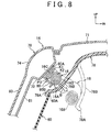
- a head protecting airbag apparatus according to the fourth embodiment of the invention will be described below with reference to FIG. 8 .
- FIG. 8 is a sectional view of the head protecting airbag system 10 according to the fourth embodiment of the invention, which correspond to FIG. 7 .
- the airbag 16 is larger in dimension in the vehicle height direction.
- a fold P 3 is formed between the position K 1 at the top end of the upper-end side inflation section 46 and the position K 2 at the bottom end thereof.
- the airbag 16 also includes the folded part 16 C located between the rolled part 16 B and the longitudinal wall 80 A of the jump stand 80 .
- inflating the folded part 16 C during the initial stage of deployment of the airbag 16 allows the rolled part 16 B of the airbag 16 to be pushed towards the passenger compartment (in the direction shown by the arrow B in FIG. 8 ) with greater force. Consequently, the terminal part 78 B of the headliner 78 is largely opened so that the airbag 16 is deployed smoothly downward along the side of the vehicle body in the passenger compartment without interference from the top end 60 A of the B-pillar garnish 60 .
- a head protecting airbag apparatus according to the fifth embodiment of the invention will be described below with reference to FIG. 9 .
- FIG. 9 is a sectional view of the head protecting airbag system 10 according to the fifth embodiment of the invention, which corresponds to FIG. 7 .
- the airbag 16 is further larger in dimension in the vehicle height direction.
- folds P 4 and P 5 are formed between the position K 1 at the top end of the upper-end side inflation section 46 and the position K 2 at the bottom end thereof.
- the airbag 16 also includes the folded part 16 C located between the rolled part 16 B and the longitudinal wall 80 A of the jump stand 80 .
- the supplemental inflation parts 46 B and 46 D which form the respective push-out parts 62 and 102 , have a semicircular shape when viewed from the side of the vehicle.
- the present invention is not limited to the described shape.
- the supplemental inflation parts 46 B and 46 D may have other shapes, such as, for example, a semi-oval shape, when viewed from the side of the vehicle.
- the invention is applied to the vehicle with two-row seating including the front seat 26 and the rear seat 30 , the invention is not limited to that.
- the invention may also be applied to vehicles with three-row seating or other seating arrangement.
- the gas injecting portion of the inflator 12 is directly inserted into the gas introducing section 47 of the airbag 16 to fix the inflator 12 to the gas introducing section 47 .
- the invention is not limited to that.
- a diffuser (pipe) or other member may be used to connect the gas introducing section 47 and the inflator 12 .
- the inflator centering arrangement is employed, in which the inflator 12 is located at around the longitudinal middle of the upper edge side of the airbag 16 .
- other arrangement may be employed, in which the inflator 12 is provided, for example, at the location of the garnish of the D-pillar 22 .
- one inflator 12 is used to inject gas into the airbag 16 in the described embodiments.
- the invention is not limited to that.
- two or more inflators 12 may be used to inject gas into the airbag 16 .
Landscapes
- Engineering & Computer Science (AREA)
- Mechanical Engineering (AREA)
- Air Bags (AREA)
Applications Claiming Priority (2)
| Application Number | Priority Date | Filing Date | Title |
|---|---|---|---|
| JP2006-236019 | 2006-08-31 | ||
| JP2006236019A JP4221017B2 (ja) | 2006-08-31 | 2006-08-31 | 頭部保護エアバッグ装置 |
Publications (2)
| Publication Number | Publication Date |
|---|---|
| US20080054605A1 US20080054605A1 (en) | 2008-03-06 |
| US7806433B2 true US7806433B2 (en) | 2010-10-05 |
Family
ID=39150437
Family Applications (1)
| Application Number | Title | Priority Date | Filing Date |
|---|---|---|---|
| US11/892,889 Active 2029-02-27 US7806433B2 (en) | 2006-08-31 | 2007-08-28 | Head protecting airbag system |
Country Status (2)
| Country | Link |
|---|---|
| US (1) | US7806433B2 (ja) |
| JP (1) | JP4221017B2 (ja) |
Cited By (12)
| Publication number | Priority date | Publication date | Assignee | Title |
|---|---|---|---|---|
| US20110101658A1 (en) * | 2008-04-23 | 2011-05-05 | Ashimori Industry Co., Ltd. | Airbag device |
| US20120223511A1 (en) * | 2011-03-03 | 2012-09-06 | Takata-Petri Ag | Airbag for a vehicle occupant restraint system in a motor vehicle and a procedure for manufacturing such an airbag |
| US20140306431A1 (en) * | 2013-04-16 | 2014-10-16 | Tk Holdings Inc. | Airbag device |
| US9248800B1 (en) | 2014-09-26 | 2016-02-02 | Toyota Motor Engineering & Manufacturing North America, Inc. | Side pillar assemblies with retention structures for side airbags |
| US9889812B1 (en) * | 2016-11-01 | 2018-02-13 | Ford Global Technologies, Llc | Side-curtain airbag assembly |
| US9994187B2 (en) * | 2016-03-29 | 2018-06-12 | Toyoda Gosei Co., Ltd. | Folding completion body of head-protecting airbag |
| US20180290617A1 (en) * | 2015-06-05 | 2018-10-11 | Autoliv Development Ab | Curtain airbag device |
| US20200017058A1 (en) * | 2018-07-11 | 2020-01-16 | Ford Global Technologies, Llc | Pillar airbag assembly |
| US10744960B2 (en) | 2015-08-28 | 2020-08-18 | Ford Global Technologies, Llc | Vehicle interior trim assembly and method of forming the same |
| US10875487B2 (en) | 2018-01-26 | 2020-12-29 | Autoliv Development Ab | Side airbag device |
| US11535187B2 (en) * | 2018-11-29 | 2022-12-27 | Dalphi Metal Espana, S.A. | Airbag module and method of manufacturing said airbag module |
| US20230202419A1 (en) * | 2020-05-28 | 2023-06-29 | Yoshiki Ito | Airbag device |
Families Citing this family (11)
| Publication number | Priority date | Publication date | Assignee | Title |
|---|---|---|---|---|
| JP2009286300A (ja) * | 2008-05-30 | 2009-12-10 | Takata Corp | 頭部拘束エアバッグ装置 |
| JP5520654B2 (ja) * | 2010-03-26 | 2014-06-11 | 本田技研工業株式会社 | 乗員拘束装置 |
| JP5623355B2 (ja) * | 2010-07-30 | 2014-11-12 | オートリブ ディベロップメント エービー | カーテンエアバッグ |
| JP2012148638A (ja) * | 2011-01-18 | 2012-08-09 | Nippon Plast Co Ltd | カーテンエアバッグ装置 |
| JP5783818B2 (ja) * | 2011-06-23 | 2015-09-24 | 芦森工業株式会社 | エアバッグ装置 |
| KR101316472B1 (ko) * | 2011-09-21 | 2013-10-08 | 현대자동차주식회사 | 차량용 센터 커튼 에어백 장치 |
| JP5826093B2 (ja) * | 2012-03-30 | 2015-12-02 | タカタ株式会社 | 頭部保護エアバッグ装置 |
| JP5770688B2 (ja) * | 2012-07-09 | 2015-08-26 | オートリブ ディベロップメント エービー | カーテンエアバッグ |
| JP2015171894A (ja) * | 2015-06-30 | 2015-10-01 | オートリブ ディベロップメント エービー | カーテンエアバッグ装置 |
| JP6708108B2 (ja) * | 2016-12-07 | 2020-06-10 | トヨタ自動車株式会社 | 車両用カーテンエアバッグ装置 |
| CN113815559B (zh) * | 2021-10-22 | 2022-12-30 | 上海临港均胜汽车安全系统有限公司 | 一种气帘装置 |
Citations (36)
| Publication number | Priority date | Publication date | Assignee | Title |
|---|---|---|---|---|
| JPH11321538A (ja) | 1998-03-18 | 1999-11-24 | Trw Vehicle Safety Syst Inc | 車両搭乗者安全装置 |
| US6123355A (en) * | 1998-03-18 | 2000-09-26 | Trw Vehicle Safety Systems Inc. | Vehicle occupant safety apparatus |
| US6254123B1 (en) * | 1998-08-03 | 2001-07-03 | Toyota Jidosha Kabushiki Kaisha | Mounting structure for use with a head-protecting airbag body |
| US6305707B1 (en) * | 1998-05-12 | 2001-10-23 | Toyota Jidosha Kabushiki Kaisha | Structure for placement of head protecting air bag apparatus |
| US6361069B1 (en) * | 1999-08-23 | 2002-03-26 | Toyota Jidosha Kabushiki Kaisha | Head-protection air-bag device |
| US6371512B1 (en) | 1998-08-03 | 2002-04-16 | Toyota Jidosha Kabushiki Kaisha | Airbag apparatus for head-protecting |
| US6471240B2 (en) * | 2000-03-17 | 2002-10-29 | Trw Vehicle Safety Systems Inc. | Inflatable side curtain |
| JP2002337648A (ja) | 2001-05-16 | 2002-11-27 | Toyota Motor Corp | 頭部保護エアバッグ装置 |
| JP2003011767A (ja) | 2001-06-29 | 2003-01-15 | Toyoda Gosei Co Ltd | 頭部保護エアバッグ装置のエアバッグ |
| US6520533B2 (en) * | 1999-12-27 | 2003-02-18 | Toyoda Gosei Co., Ltd. | Head protecting air bag apparatus |
| US6527296B2 (en) * | 2000-03-17 | 2003-03-04 | Trw Vehicle Safety Systems Inc. | Inflatable side curtain |
| US6530594B1 (en) * | 1997-09-26 | 2003-03-11 | Toyota Jidosha Kabushiki Kaisha | Placement structure for head-protecting air bag body |
| JP2004058848A (ja) | 2002-07-29 | 2004-02-26 | Toyoda Gosei Co Ltd | 頭部保護エアバッグ装置 |
| JP2004106722A (ja) | 2002-09-19 | 2004-04-08 | Toyoda Gosei Co Ltd | 頭部保護エアバッグ装置 |
| US6722693B2 (en) * | 2002-04-02 | 2004-04-20 | Toyoda Gosei Co., Ltd. | Airbag |
| US6742806B2 (en) * | 2001-01-11 | 2004-06-01 | Toyoda Gosei Co., Ltd. | Airbag and its wrapping method |
| US6758490B2 (en) | 2001-04-25 | 2004-07-06 | Autoliv Asp, Inc. | Apparatus and method for inflatable combination curtain fold |
| US6811184B2 (en) * | 2001-11-12 | 2004-11-02 | Toyoda Gosei Co., Ltd. | Head protecting airbag device |
| JP2005029035A (ja) | 2003-07-07 | 2005-02-03 | Toyoda Gosei Co Ltd | 頭部保護エアバッグ装置 |
| US20060131849A1 (en) * | 2004-12-21 | 2006-06-22 | Toyoda Gosei Co., Ltd. | Head-protecting airbag apparatus |
| US7077425B2 (en) * | 2002-09-19 | 2006-07-18 | Toyoda Gosei Co., Ltd. | Head protecting airbag device |
| US7080853B2 (en) * | 2002-11-27 | 2006-07-25 | Toyoda Gosei Co., Ltd. | Airbag for head-protecting airbag device |
| US7114744B2 (en) * | 2003-02-20 | 2006-10-03 | Nissan Motor Co., Ltd. | Airbag apparatus and related method |
| US7163232B2 (en) * | 2001-11-26 | 2007-01-16 | Nihon Plast Co., Ltd. | Curtain airbag and its folding method and system |
| US7172211B2 (en) * | 2004-04-27 | 2007-02-06 | Honda Motor Co., Ltd. | Occupant restraint system |
| US7213836B2 (en) * | 2004-08-25 | 2007-05-08 | Key Safety Systems, Inc. | Curtain air bag module |
| US7267364B2 (en) * | 2003-12-19 | 2007-09-11 | Takata Corporation | Curtain airbag device |
| US7273228B2 (en) * | 2003-12-19 | 2007-09-25 | Takata Corporation | Guide unit for guiding curtain airbag and curtain airbag device |
| US7278655B2 (en) * | 2003-09-24 | 2007-10-09 | Toyoda Gosei Co., Ltd. | Head-protecting airbag |
| US7322600B2 (en) * | 2003-11-27 | 2008-01-29 | Toyoda Gosei Co., Ltd. | Head-protecting airbag |
| US7338071B2 (en) * | 2003-12-19 | 2008-03-04 | Takata Corporation | Guide unit for guiding curtain airbag and curtain airbag device |
| US7347447B2 (en) * | 2004-11-05 | 2008-03-25 | Takata Corporation | Curtain airbag device |
| US7350804B2 (en) * | 2004-11-08 | 2008-04-01 | Trw Vehicle Safety Systems Inc. | Inflatable vehicle occupant protection device with thorax protection |
| US7404790B2 (en) * | 2005-01-28 | 2008-07-29 | Toyoda Gosei Co., Ltd. | Airbag folding method and folding device |
| US7731227B2 (en) * | 2007-04-02 | 2010-06-08 | Toyoda Gosei Co., Ltd. | Head protection airbag device |
| US7731225B2 (en) * | 2005-12-07 | 2010-06-08 | Nihon Plast Co., Ltd. | Airbag apparatus for vehicle |
-
2006
- 2006-08-31 JP JP2006236019A patent/JP4221017B2/ja active Active
-
2007
- 2007-08-28 US US11/892,889 patent/US7806433B2/en active Active
Patent Citations (40)
| Publication number | Priority date | Publication date | Assignee | Title |
|---|---|---|---|---|
| US6530594B1 (en) * | 1997-09-26 | 2003-03-11 | Toyota Jidosha Kabushiki Kaisha | Placement structure for head-protecting air bag body |
| US6123355A (en) * | 1998-03-18 | 2000-09-26 | Trw Vehicle Safety Systems Inc. | Vehicle occupant safety apparatus |
| JPH11321538A (ja) | 1998-03-18 | 1999-11-24 | Trw Vehicle Safety Syst Inc | 車両搭乗者安全装置 |
| US6305707B1 (en) * | 1998-05-12 | 2001-10-23 | Toyota Jidosha Kabushiki Kaisha | Structure for placement of head protecting air bag apparatus |
| US6254123B1 (en) * | 1998-08-03 | 2001-07-03 | Toyota Jidosha Kabushiki Kaisha | Mounting structure for use with a head-protecting airbag body |
| US6371512B1 (en) | 1998-08-03 | 2002-04-16 | Toyota Jidosha Kabushiki Kaisha | Airbag apparatus for head-protecting |
| US6361069B1 (en) * | 1999-08-23 | 2002-03-26 | Toyota Jidosha Kabushiki Kaisha | Head-protection air-bag device |
| US6520533B2 (en) * | 1999-12-27 | 2003-02-18 | Toyoda Gosei Co., Ltd. | Head protecting air bag apparatus |
| US6527296B2 (en) * | 2000-03-17 | 2003-03-04 | Trw Vehicle Safety Systems Inc. | Inflatable side curtain |
| US6471240B2 (en) * | 2000-03-17 | 2002-10-29 | Trw Vehicle Safety Systems Inc. | Inflatable side curtain |
| US6742806B2 (en) * | 2001-01-11 | 2004-06-01 | Toyoda Gosei Co., Ltd. | Airbag and its wrapping method |
| US6758490B2 (en) | 2001-04-25 | 2004-07-06 | Autoliv Asp, Inc. | Apparatus and method for inflatable combination curtain fold |
| JP2002337648A (ja) | 2001-05-16 | 2002-11-27 | Toyota Motor Corp | 頭部保護エアバッグ装置 |
| JP2003011767A (ja) | 2001-06-29 | 2003-01-15 | Toyoda Gosei Co Ltd | 頭部保護エアバッグ装置のエアバッグ |
| JP3656156B2 (ja) | 2001-06-29 | 2005-06-08 | 豊田合成株式会社 | 頭部保護エアバッグ装置のエアバッグ |
| US6811184B2 (en) * | 2001-11-12 | 2004-11-02 | Toyoda Gosei Co., Ltd. | Head protecting airbag device |
| US7163232B2 (en) * | 2001-11-26 | 2007-01-16 | Nihon Plast Co., Ltd. | Curtain airbag and its folding method and system |
| US6722693B2 (en) * | 2002-04-02 | 2004-04-20 | Toyoda Gosei Co., Ltd. | Airbag |
| JP2004058848A (ja) | 2002-07-29 | 2004-02-26 | Toyoda Gosei Co Ltd | 頭部保護エアバッグ装置 |
| US7077425B2 (en) * | 2002-09-19 | 2006-07-18 | Toyoda Gosei Co., Ltd. | Head protecting airbag device |
| JP2004106722A (ja) | 2002-09-19 | 2004-04-08 | Toyoda Gosei Co Ltd | 頭部保護エアバッグ装置 |
| JP3915643B2 (ja) | 2002-09-19 | 2007-05-16 | 豊田合成株式会社 | 頭部保護エアバッグ装置 |
| US7080853B2 (en) * | 2002-11-27 | 2006-07-25 | Toyoda Gosei Co., Ltd. | Airbag for head-protecting airbag device |
| US7114744B2 (en) * | 2003-02-20 | 2006-10-03 | Nissan Motor Co., Ltd. | Airbag apparatus and related method |
| JP2005029035A (ja) | 2003-07-07 | 2005-02-03 | Toyoda Gosei Co Ltd | 頭部保護エアバッグ装置 |
| US7278655B2 (en) * | 2003-09-24 | 2007-10-09 | Toyoda Gosei Co., Ltd. | Head-protecting airbag |
| US7322600B2 (en) * | 2003-11-27 | 2008-01-29 | Toyoda Gosei Co., Ltd. | Head-protecting airbag |
| US7273228B2 (en) * | 2003-12-19 | 2007-09-25 | Takata Corporation | Guide unit for guiding curtain airbag and curtain airbag device |
| US7267364B2 (en) * | 2003-12-19 | 2007-09-11 | Takata Corporation | Curtain airbag device |
| US7338071B2 (en) * | 2003-12-19 | 2008-03-04 | Takata Corporation | Guide unit for guiding curtain airbag and curtain airbag device |
| US7172211B2 (en) * | 2004-04-27 | 2007-02-06 | Honda Motor Co., Ltd. | Occupant restraint system |
| US7213836B2 (en) * | 2004-08-25 | 2007-05-08 | Key Safety Systems, Inc. | Curtain air bag module |
| US7347447B2 (en) * | 2004-11-05 | 2008-03-25 | Takata Corporation | Curtain airbag device |
| US7350804B2 (en) * | 2004-11-08 | 2008-04-01 | Trw Vehicle Safety Systems Inc. | Inflatable vehicle occupant protection device with thorax protection |
| JP2006175920A (ja) | 2004-12-21 | 2006-07-06 | Toyoda Gosei Co Ltd | 頭部保護エアバッグ装置 |
| US20060131849A1 (en) * | 2004-12-21 | 2006-06-22 | Toyoda Gosei Co., Ltd. | Head-protecting airbag apparatus |
| US7673897B2 (en) * | 2004-12-21 | 2010-03-09 | Toyoda Gosei Co., Ltd. | Head-protecting airbag apparatus |
| US7404790B2 (en) * | 2005-01-28 | 2008-07-29 | Toyoda Gosei Co., Ltd. | Airbag folding method and folding device |
| US7731225B2 (en) * | 2005-12-07 | 2010-06-08 | Nihon Plast Co., Ltd. | Airbag apparatus for vehicle |
| US7731227B2 (en) * | 2007-04-02 | 2010-06-08 | Toyoda Gosei Co., Ltd. | Head protection airbag device |
Cited By (17)
| Publication number | Priority date | Publication date | Assignee | Title |
|---|---|---|---|---|
| US8308192B2 (en) * | 2008-04-23 | 2012-11-13 | Ashimori Industry Co., Ltd. | Airbag device |
| US20110101658A1 (en) * | 2008-04-23 | 2011-05-05 | Ashimori Industry Co., Ltd. | Airbag device |
| US20120223511A1 (en) * | 2011-03-03 | 2012-09-06 | Takata-Petri Ag | Airbag for a vehicle occupant restraint system in a motor vehicle and a procedure for manufacturing such an airbag |
| US8678428B2 (en) * | 2011-03-03 | 2014-03-25 | Takata AG | Airbag for a vehicle occupant restraint system in a motor vehicle and a procedure for manufacturing such an airbag |
| US20140306431A1 (en) * | 2013-04-16 | 2014-10-16 | Tk Holdings Inc. | Airbag device |
| US9090223B2 (en) * | 2013-04-16 | 2015-07-28 | Tk Holdings Inc. | Airbag device |
| US9248800B1 (en) | 2014-09-26 | 2016-02-02 | Toyota Motor Engineering & Manufacturing North America, Inc. | Side pillar assemblies with retention structures for side airbags |
| US20180290617A1 (en) * | 2015-06-05 | 2018-10-11 | Autoliv Development Ab | Curtain airbag device |
| US10654438B2 (en) * | 2015-06-05 | 2020-05-19 | Autoliv Development Ab | Curtain airbag device |
| US10744960B2 (en) | 2015-08-28 | 2020-08-18 | Ford Global Technologies, Llc | Vehicle interior trim assembly and method of forming the same |
| US9994187B2 (en) * | 2016-03-29 | 2018-06-12 | Toyoda Gosei Co., Ltd. | Folding completion body of head-protecting airbag |
| US9889812B1 (en) * | 2016-11-01 | 2018-02-13 | Ford Global Technologies, Llc | Side-curtain airbag assembly |
| US10875487B2 (en) | 2018-01-26 | 2020-12-29 | Autoliv Development Ab | Side airbag device |
| US20200017058A1 (en) * | 2018-07-11 | 2020-01-16 | Ford Global Technologies, Llc | Pillar airbag assembly |
| US10981531B2 (en) * | 2018-07-11 | 2021-04-20 | Ford Global Technologies, Llc | Pillar airbag assembly |
| US11535187B2 (en) * | 2018-11-29 | 2022-12-27 | Dalphi Metal Espana, S.A. | Airbag module and method of manufacturing said airbag module |
| US20230202419A1 (en) * | 2020-05-28 | 2023-06-29 | Yoshiki Ito | Airbag device |
Also Published As
| Publication number | Publication date |
|---|---|
| US20080054605A1 (en) | 2008-03-06 |
| JP4221017B2 (ja) | 2009-02-12 |
| JP2008056116A (ja) | 2008-03-13 |
Similar Documents
| Publication | Publication Date | Title |
|---|---|---|
| US7806433B2 (en) | Head protecting airbag system | |
| US7832760B2 (en) | Head protecting airbag system | |
| US7441796B2 (en) | Airbag system | |
| US8235418B2 (en) | Airbag | |
| CN106915324B (zh) | 安全气囊装置 | |
| US8579323B2 (en) | Curtain airbag system | |
| US7854448B2 (en) | Airbag arrangement | |
| EP1953046B1 (en) | Vehicle occupant restraint system | |
| US11148633B2 (en) | Vehicle airbag device | |
| EP1533196B1 (en) | Airbag system | |
| US11358560B2 (en) | Side curtain air bag | |
| KR102005748B1 (ko) | 자동차의 커튼 에어백 | |
| JP5236907B2 (ja) | 頭部保護エアバッグ装置 | |
| US20050140122A1 (en) | Airbag apparatus | |
| US11427151B2 (en) | Airbag | |
| JP2008056121A (ja) | 頭部保護エアバッグ装置 | |
| JP4721987B2 (ja) | 頭部保護エアバッグ装置 | |
| US8002311B2 (en) | Airbag with sections of different deployment lengths | |
| US10940823B2 (en) | Occupant protection device for a motor vehicle and motor vehicle | |
| KR20220151456A (ko) | 자동차의 커튼 에어백 | |
| JP2008056119A (ja) | 頭部保護エアバッグ装置 |
Legal Events
| Date | Code | Title | Description |
|---|---|---|---|
| AS | Assignment |
Owner name: AUTOLIV DEVELOPMENT AB, SWEDEN Free format text: ASSIGNMENT OF ASSIGNORS INTEREST;ASSIGNORS:MITSUO, TETSU;NARUI, AKIHIKO;NOGAMI, MITSUO;REEL/FRAME:020048/0617 Effective date: 20071019 Owner name: TOYOTA JIDOSHA KABUSHIKI KAISHA, JAPAN Free format text: ASSIGNMENT OF ASSIGNORS INTEREST;ASSIGNORS:MITSUO, TETSU;NARUI, AKIHIKO;NOGAMI, MITSUO;REEL/FRAME:020048/0617 Effective date: 20071019 |
|
| STCF | Information on status: patent grant |
Free format text: PATENTED CASE |
|
| FEPP | Fee payment procedure |
Free format text: PAYOR NUMBER ASSIGNED (ORIGINAL EVENT CODE: ASPN); ENTITY STATUS OF PATENT OWNER: LARGE ENTITY |
|
| FPAY | Fee payment |
Year of fee payment: 4 |
|
| MAFP | Maintenance fee payment |
Free format text: PAYMENT OF MAINTENANCE FEE, 8TH YEAR, LARGE ENTITY (ORIGINAL EVENT CODE: M1552) Year of fee payment: 8 |
|
| MAFP | Maintenance fee payment |
Free format text: PAYMENT OF MAINTENANCE FEE, 12TH YEAR, LARGE ENTITY (ORIGINAL EVENT CODE: M1553); ENTITY STATUS OF PATENT OWNER: LARGE ENTITY Year of fee payment: 12 |