US7784666B2 - Method and apparatus for positioning plate members to be butt-welded - Google Patents
Method and apparatus for positioning plate members to be butt-welded Download PDFInfo
- Publication number
- US7784666B2 US7784666B2 US11/916,541 US91654105A US7784666B2 US 7784666 B2 US7784666 B2 US 7784666B2 US 91654105 A US91654105 A US 91654105A US 7784666 B2 US7784666 B2 US 7784666B2
- Authority
- US
- United States
- Prior art keywords
- members
- plate
- positioning
- pushing
- plate members
- Prior art date
- Legal status (The legal status is an assumption and is not a legal conclusion. Google has not performed a legal analysis and makes no representation as to the accuracy of the status listed.)
- Expired - Fee Related
Links
Images


Classifications
-
- B—PERFORMING OPERATIONS; TRANSPORTING
- B23—MACHINE TOOLS; METAL-WORKING NOT OTHERWISE PROVIDED FOR
- B23K—SOLDERING OR UNSOLDERING; WELDING; CLADDING OR PLATING BY SOLDERING OR WELDING; CUTTING BY APPLYING HEAT LOCALLY, e.g. FLAME CUTTING; WORKING BY LASER BEAM
- B23K37/00—Auxiliary devices or processes, not specially adapted for a procedure covered by only one of the other main groups of this subclass
- B23K37/04—Auxiliary devices or processes, not specially adapted for a procedure covered by only one of the other main groups of this subclass for holding or positioning work
- B23K37/0408—Auxiliary devices or processes, not specially adapted for a procedure covered by only one of the other main groups of this subclass for holding or positioning work for planar work
-
- B—PERFORMING OPERATIONS; TRANSPORTING
- B23—MACHINE TOOLS; METAL-WORKING NOT OTHERWISE PROVIDED FOR
- B23K—SOLDERING OR UNSOLDERING; WELDING; CLADDING OR PLATING BY SOLDERING OR WELDING; CUTTING BY APPLYING HEAT LOCALLY, e.g. FLAME CUTTING; WORKING BY LASER BEAM
- B23K37/00—Auxiliary devices or processes, not specially adapted for a procedure covered by only one of the other main groups of this subclass
- B23K37/04—Auxiliary devices or processes, not specially adapted for a procedure covered by only one of the other main groups of this subclass for holding or positioning work
- B23K37/0461—Welding tables
Definitions
- the present invention relates to positioning of plate members to be butt-welded and more particularly relates to a method and an apparatus for positioning plate members to be butt-welded, which are especially useful, for example, in welding into a tailored blank or in butt-welding of thin sheets.
- a panel component comprising steel plates with the same quality and with the same or different thicknesses is used as a blank for formation into, for example, a chassis panel of an automobile.
- a panel component comprising, for example, steel plates with different thicknesses in combination has been produced such that plates with thick and thin thicknesses are firstly punched out, for example, by presses into required shapes and are individually formed and then are connected together, for example, through spot welding to thereby assemble the panel component.
- plates with thick and thin thicknesses are firstly punched out, for example, by presses into required shapes and are individually formed and then are connected together, for example, through spot welding to thereby assemble the panel component.
- Such process is disadvantageous in increased production cost due to much working man-hour.
- an entire panel component is made from a single thick steel plate, which may disadvantageously lead to increase in weight and in cost.
- a process such that, for example, steel plates with different thicknesses are butted together and are integrated into a so-called tailored blank through CO 2 (carbon dioxide) laser welding, plasma welding, etc.
- CO 2 carbon dioxide
- plasma welding etc.
- steel plates with thick and thin thicknesses are butt-welded into a tailored blank which may be, for example, press-formed into a panel component with a predetermined shape.
- the above-mentioned process using a tailored blank has effects of substantially reducing working man-hour and production cost in comparison with assembling of a panel component by, for example, spot welding and is advantageous in weight reduction in comparison with formation of an entire panel component from a single thick steel plate.
- discards or scraps from various pressing processes may be utilized, advantageously resulting in reduction of waste of and increase in yield of material.
- the tailored blank which has been integrated through continuous welding of steel plates, has an advantage that it has welding strength substantially increased in comparison with use of spot welding.
- Such reference positioning mechanism is worked with first and second tables divided on which one and the other plate members to be butt-welded are rested, respectively, said tables being relatively movable toward and away from each other. Firstly, with the tables being separated, the one plate member on the first table is caused to abut at its end against a reference plate upwardly protruded over an upper surface of the first table, and is locked with the end being positioned. Then, the reference plate is retracted below the upper surface of the first table; and the second table is moved toward the first table to make the other plate member on the second table abut at its end against the positioned one plate member on the first table, thereby providing weld line between the plate members.
- the one plate member is positioned on the first table, and then the second table with the other plate member rested thereon is moved for abutment and positioning of the other plate member at its opposing end against an opposing end of the positioned one plate member, thereby providing weld line in position.
- the two positioning operations of the plate members are needed for formation of the weld line, much time is required for the positioning, which may disadvantageously leads to prolongation of time required for welding in mass production of tailored blanks by the welding and thus lowering of production efficiency.
- the invention was made in view of the above and has its object to provide a method and an apparatus for positioning plate members to be butt-welded by which plate members to be butt-welded can be positioned for formation of weld line in a small amount of time, thereby substantially enhancing efficiency of butt welding.
- a method for positioning plate members to be welded according to the invention is characterized in that it comprises the steps of resting plate members respectively on first and second tables relatively movable toward and away from each other, causing said plate members to abut for positioning against a reference positioning device protruded ahead of and upwardly over opposing ends of the tables and positioning said plate members laterally, locking the positioned plate members on the tables, retracting the reference positioning device, and moving the tables relatively toward each other into abutment of the opposing ends of the tables together for formation of weld line.
- An apparatus for positioning plate members to be welded is characterized in that it comprises first and second tables relatively movable toward and away from each other and each having a platform for the plate member, plate-member supports coplanar with the platform of the table, a reference positioning device provided ahead of an opposing end of said platform and adapted to be protruded upward into positioning position where an opposing end of the plate member on the plate-member supports is pushed by a pushing device for abutment against the upwardly protruded reference positioning device to thereby be positioned in protrusion ahead of an opposing end of the table, said reference positioning device being retractable from said positioning position, a lateral positioning device for laterally positioning the plate member having been longitudinally positioned and a press-locking device for locking the positioned plate member on the platform, the tables with the plate members locked thereon being relatively moved toward each other with said reference positioning devices being retracted, whereby the opposing ends of the plate members are caused to abut against each other for formation of weld line.
- the apparatus for positioning the plate members to be welded is characterized in that said reference positioning device comprises at least a pair of laterally spaced reference positioning members.
- the apparatus for positioning the plate members to be welded is characterized in that said pushing device comprises a horizontally rotatable pushing roll supported by a resilient member.
- the apparatus for positioning the plate members to be welded is characterized in that said lateral positioning apparatus comprises a pair of pushing members laterally and relatively movable toward and away from each other, one of said pushing members being a laterally positioning pusher, the other of said pushing members being a resilient pusher supported by a resilient member.
- the apparatus for positioning the plate members to be welded is characterized in that said press-locking device is gantry-shaped and is constructed such that an opposing-end-side upper surface of the plate member positioned on the table is releasably pushed by pressing members against the platform.
- the apparatus for positioning the plate members to be welded is characterized in that said press-locking device comprises a gantry frame, said frame having pressing members arranged longitudinally of and on a lower portion of said frame via resilient members.
- a plate member is rested on each of first and second tables relatively movable toward and away from each other; an opposing end of the plate member is positioned in protrusion ahead of an opposing end of the table by a reference positioning device provided ahead of the opposing end of the table and is locked; then, after the reference positioning device is retracted away from the positioning position, the tables are relatively moved toward each other to cause the opposing ends of the plate member to abut together for formation of weld line.
- weld line can be formed in a short period of time.
- a plate member is rested on each of first and second tables relatively movable toward and away from each other; a reference positioning device provided ahead of an opposing end of each of the tables is protruded so that the opposing end of the plate member is positioned in protrusion ahead of the opposing end of the table and is locked; and then, after the reference positioning device is retracted away from the positioning position, the tables are relatively moved toward each other to cause the opposing ends of the plate members to abut together to thereby form weld line.
- the invention which can conduct butt-welding after finishing the positioning of the plate members in a single operation has advantages or effects that working hours can be substantially reduced and thus working efficiency of butt-welding can be substantially enhanced.
- FIG. 1 is an entire plan view of an embodiment of an apparatus for positioning plate members to be butt-welded according to the invention
- FIG. 2 is a side view looking in the direction of arrows II in FIG. 1 ;
- FIG. 3 is a side view looking in the direction of arrows III in FIG. 1 ;
- FIG. 4 is a front view looking in the direction of arrows IV in FIG. 3 ;
- FIG. 5 is a side view showing an embodiment of a reference positioning device
- FIG. 6 is a front view looking from left in FIG. 5 ;
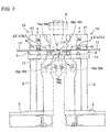
- FIG. 7 is a side view for showing operation of the reference positioning members and the pressing members for the first and second tables
- FIG. 8 is a side view showing the structure of a movement block of a pushing device on the first table
- FIG. 9 is a front view showing the movement block looking from left in FIG. 8 ;
- FIG. 10 is a plan view of the movement block shown in FIG. 8 ;
- FIG. 11 is a front view showing the structure of a right pushing member
- FIG. 12 is a side view of the right pushing member looking from right in FIG. 11 ;
- FIG. 13 is a plan view of the right pushing member shown in FIG. 11 ;
- FIG. 14 is a front view showing the structure of a left pushing member.
- FIG. 15 is a side view showing the structure of a press-locking device.
- FIG. 16 is a front view of the press-locking device looking from left in FIG. 15 ;
- FIGS. 17(A) , (B), (C), (D), (E) and (F) are schematic step view showing stepwise the operation of a positioning method according to the invention.
- FIG. 1 is an entire plan view of an embodiment of an apparatus for positioning plate members to be butt-welded according to the invention
- FIG. 2 is a side view looking in the direction of arrows II in FIG. 1
- FIG. 3 is a side view looking in the direction of arrows III in FIG. 1
- FIG. 4 is a front view looking in the direction of arrows IV in FIG. 3 .
- a rear- and front-side first and second table 1 A and 1 B relatively movable toward and away from each other longitudinally (axially of the apparatus) through liner motion (LM) guides 3 .
- LM liner motion
- Each of the tables 1 A and 1 B has a laterally elongated slider 4 adapted to be longitudinally movable along the LM guide 3 by a drive 4 a such as air cylinder.
- Each of the sliders 4 has vertical pillars 5 arranged on lateral sides, respectively.
- the left and right pillars 5 have a platform 6 locked to and extending between upper ends of the pillars 5 to receive a laterally extending plate member 17 (see FIG. 7 ).
- the support member 7 has, on its top, a plurality of short plate-member supports 7 a such as pipes which extend horizontally and longitudinally and are laterally spaced apart from each other to be protruded above the slider 4 .
- the plate-member supports 7 a are arranged to be coplanar at their upper surfaces with upper surface of the platform 6 .
- the description has been made on the tables 1 A and 1 B longitudinally movable for relative movement toward and away from each other; alternatively, one and the other of the tables 1 A and 1 B may be made immovable and movable, respectively, for their relative movement toward and away from each other.
- support members 8 are also locked on the mounting 2 with respect to each of the tables 1 A and 1 B which are aligned with and spaced apart from the short plate-member supports 7 a.
- the above embodiment has been illustrated on the plate-member supports 7 a and 7 b locked with respect to the mounting 2 , alternatively the supports 7 a and 7 b may be arranged on the tables 1 A and 1 B for their longitudinal movement together with the tables 1 A and 1 B.
- a welder 9 adapted to be laterally moved to carry out flat-position welding.
- a sealing member 10 supported, for example, by a pillar 10 a to seal a lower region for retaining of an atmosphere due to inert gas blown from upward upon welding by the welder 9 .
- FIGS. 5 and 6 Arranged between upper ends of the pillars 5 on the lateral sides of the front and rear sliders 4 is, as shown in FIGS. 5 and 6 , reference positioning devices 12 each adapted to be rotated about a pivot shaft 11 .
- FIG. 5 shows only the reference positioning device 12 on the second table 1 B, the similar reference positioning device 12 being also provided on the first table 1 A.
- the reference positioning device 12 comprises short arms 13 each pivoted at its one end to the pivot shaft 11 on the pillar 5 and a laterally elongated positioning frame 14 arranged between and locked to the other ends of the arms 13 .
- an actuator 15 such as air cylinder adapted to selectively swing the arm 13 into a horizontally protruded state ahead of the table 1 A or 1 B and into a vertically downwardly retracted state.
- an actuator 15 such as air cylinder adapted to selectively swing the arm 13 into a horizontally protruded state ahead of the table 1 A or 1 B and into a vertically downwardly retracted state.
- Arranged on the positioning frame 14 are at least a pair (two pairs in the figure) of upwardly protruded, laterally inward and outward reference positioning members 16 a and 16 b (see FIG. 1 ).
- the reference positioning member 16 a and 16 b are associated with the narrow and wide plate members 17 , respectively, and may be in the from of, for example, positioning pins or blocks.
- the reference positioning device 12 may be driven by the actuator 15 to selectively swing the reference positioning members 16 a and 16 b into protruded positions shown in solid line in FIG. 7 ahead of the opposing ends 1 ′ of the platforms 6 of the tables 1 A and 1 B, and into vertically downwardly retracted positions shown in dotted line where the front and rear reference positioning members 16 a and 16 b are adapted not to interfere with each other even if the tables 1 A and 1 B are relatively moved to each other.
- FIGS. 1 and 2 Arranged among the plate-member supports 7 b shown in FIGS. 1 and 2 are pushing devices 20 each adapted to longitudinally move a movement block 19 through a linear movement (LM) guide actuator 18 to thereby push the plate members 17 on the supports 7 a or 7 b against the reference positioning members 16 a and 16 b in FIG. 5 so as to longitudinally position the plate members 17 .
- LM linear movement
- the movement block 19 has at its right a U-shape-sided support member 21 which has, within its U-shape portion, a pushing roll 22 horizontally rotatable about a vertical shaft 23 which in turn is attached to a moving piece 25 fitted in a slot 24 on the movement block 19 so as to be movable longitudinally.
- the movement block 19 has at its left side a resilient member 26 such as spring for urging the support member 21 to the right, and has at its left end an adjusting bolt 27 for adjusting the resilience force of the resilient member 26 .
- a lateral positioning device comprising left and right pushing members 30 and 31 which relatively and laterally move movement blocks 29 through LM guide actuators 28 to laterally position the plate members 17 on the plate-member supports 7 a and 7 b.
- the movement block 29 is adapted to laterally move ahead of the opposing ends of the short plate-member supports 7 a.
- the left and right pushing members 30 and 31 are shown to respectively have auxiliary movement blocks 29 ′ arranged on LM guide actuators 28 ′ on the mounting 2 and adapted to be moved between the opposing ends of the short and long plate-member supports 7 a and 7 .
- the plate member 17 is pushed at two points or by the movement block 29 and by the auxiliary movement block 29 ′.
- FIGS. 11 , 12 and 13 show the structure of the right pushing member 31 which has at its left a cylindrical pusher 33 supported by a vertical shaft 32 which in turn is fitted into a slot 34 on the movement block 29 so as to move longitudinally.
- the movement block 29 has at its right side a resilient member 35 such as spring for pushing the pusher 33 to the left, and has at its right end an adjusting bolt 36 for adjusting resilience force of the resilient member 35 .
- the pusher 33 of the right pushing member 31 serves as a resilient pusher with resilient force due to the resilient member 35 .
- the left pushing member 30 comprises the movement block 29 which is structurally similar to that shown in FIG. 11 and which has, not the resilient member 35 for pushing the pusher 33 , but a locking piece 37 at a left side of a pusher 33 ′ so as to push the pusher 33 ′ to the right for lateral immobilization of the pusher 33 ′.
- Control is such that the left pushing member 30 is driven forward by the LM guide actuator 28 into a predetermined position and stopped, the right pushing member 31 being driven forward into a predetermined position with time lag to the left pushing member 30 .
- the left and right pushing members 30 and 31 are relatively moved toward each other so that the resilient pusher 33 supported by the resilient member 35 pushes the plate member 17 against the laterally positioning pusher 33 ′ locked in position by the locking piece 37 , whereby the plate member 17 is laterally positioned.
- a press-locking device 39 for movement about a pivot shaft 38 as shown in FIGS. 15 and 16 .
- FIG. 15 shows only the press-locking device 39 for the second table 1 B, the similar press-locking device 39 is provided also for the first table 1 A.
- the press-locking device 39 has left and right pivot arms 40 pivoted at their intermediate portions about the pivot shaft 38 on the pillars 5 . Attached to one ends of the pivot arms 40 is a frame 41 laterally extending over the platform 6 to provide a gantry which strides across the tables 1 A and 1 B.
- a plurality of pressing members 42 extending laterally and in parallel with the frame 41 .
- actuators 44 such as air cylinders driven to rotate the pivot arms 40 for lifting up and down the pressing members 42 so that the opposing-end-side upper surface of the plate member 17 , which is pushed against the members 16 a and 16 b of the reference positioning device 12 to be positioned on the table 1 A or 1 B, can be pressed by the pressing members 42 to be locked on the platform 6 or can be released by moving the pressing members 42 away from the plate member 17 .
- the plate member 17 can be locked on the platform 6 under a predetermined pressing force by the pressing members 42 even if the plate member 17 may vary in thickness or may have bent.
- FIG. 17(A) shows a state that the tables 1 A and 1 B are away from each other and the plate members 17 are transferred onto the plate-member supports 7 a and 7 b shown in FIGS. 1 and 2 .
- the pushing devices 20 are being retracted away from the reference positioning devices 12
- the left and right pushing members 30 and 31 of the lateral positioning devices being also retracted into positions relatively away from each other.
- each of the plate members 17 is transferred onto the plate-member supports 7 a and 7 b and between the reference positioning device 12 , the pushing device 20 and the left and right pushing members 30 and 31 .
- the reference positioning device 12 is being rotated upward by the operation of the actuator 15 in FIG. 5 into a position shown in solid lines so that reference positioning members 16 a and 16 b are kept protruded over the upper surface of the platform 6 on each of the tables 1 A and 1 B.
- the pressing members 42 of the press-locking device 39 is kept upwardly away from the upper surface of the platform 6 on each of the tables 1 A and 1 B as shown in two-dotted chain lines in FIG. 15 .
- the LM guide actuator 18 in FIG. 1 is driven to move the movement block 19 of the pushing device 20 and thus the plate member 17 toward the opposing end 1 ′ of each of the tables 1 A and 1 B. Then, the opposing end of the plate member 17 passes underneath the pressing members 42 and is pushed against the reference positioning members 16 a so that the plate member 17 is positioned longitudinally, the plate member being stably pushed by a predetermined pushing force since it is pushed by the pushing roll 22 supported by the resilient members 26 in the pushing device 20 as shown in FIG. 8 .
- control is made such that the movement blocks 29 and 29 ′ of the left pushing member 30 are moved forward by the LM guide actuators 28 and 28 ′ shown in FIG. 1 into a predetermined position and are stopped, and the movement blocks 29 and 29 ′ of the right pushing member 31 are moved forward with time lag to the left pushing member 30 .
- the left and right pushing members 30 and 31 are relatively moved toward each other in this manner so that the plate member 17 is laterally positioned.
- the positions into which the left and right pushing members 30 and 31 are moved forward are set in accordance with variation of lateral or widthwise size of the plate member 17 to be treated with.
- the plate member 17 having been pushed and locked to the reference positioning members 16 a by the pushing device 20 is to be pushed laterally by the left and right pushing members 30 and 31 as mentioned above, the pushed points may not be smoothly displaced, resulting in horizontal pivotal force generated on the plate member 17 and resultant deviance in positioning.
- the plate member 17 is pushed by the pushing roll 22 of the pushing device 20 and the resilient pusher 33 of the right pushing member 31 respectively supported by the resilient members 26 and 35 , so that the pushing roll 22 and the resilient pusher 33 are displaced along the plate members 17 , which eliminates the problem of pivotal force generated on the plate member 17 .
- the actuators 44 shown in FIG. 15 are driven to lower the pressing members 42 of the press-locking device 39 for locking of the positioned plate members 17 on the platform 6 of each of the tables 1 A and 1 B.
- the work of positioning and locking of the one and the other plate members 17 can be completed in a single operation.
- the drive units 4 a shown in FIG. 2 are driven to move the tables 1 A and 1 B along the LM guides 3 relatively toward each other so that the opposing ends of the plate members 17 are caused to abut against each other to form weld line X; no interference problem is caused by relative movement of the tables 1 A and 1 B toward each other since the reference positioning members 16 a and 16 b of the reference positioning device 12 are being retracted downward.
- weld line X is formed just below the welder 9 as shown in FIG. 7 and is butt-welded by for example CO 2 (carbon dioxide) laser welding or plasma welding to thereby integrate the plate members 17 .
- CO 2 carbon dioxide
Landscapes
- Physics & Mathematics (AREA)
- Optics & Photonics (AREA)
- Engineering & Computer Science (AREA)
- Mechanical Engineering (AREA)
- Laser Beam Processing (AREA)
- Butt Welding And Welding Of Specific Article (AREA)
- Lining Or Joining Of Plastics Or The Like (AREA)
- Bending Of Plates, Rods, And Pipes (AREA)
- Automatic Assembly (AREA)
Applications Claiming Priority (1)
| Application Number | Priority Date | Filing Date | Title |
|---|---|---|---|
| PCT/JP2005/010319 WO2006131957A1 (ja) | 2005-06-06 | 2005-06-06 | 突き合わせ溶接板材の位置決め方法及び装置 |
Related Parent Applications (1)
| Application Number | Title | Priority Date | Filing Date |
|---|---|---|---|
| PCT/JP2005/010319 A-371-Of-International WO2006131957A1 (ja) | 2005-06-06 | 2005-06-06 | 突き合わせ溶接板材の位置決め方法及び装置 |
Related Child Applications (1)
| Application Number | Title | Priority Date | Filing Date |
|---|---|---|---|
| US12/717,414 Division US7828194B2 (en) | 2005-06-06 | 2010-03-04 | Method for positioning plate members to be butt-welded |
Publications (2)
| Publication Number | Publication Date |
|---|---|
| US20080265007A1 US20080265007A1 (en) | 2008-10-30 |
| US7784666B2 true US7784666B2 (en) | 2010-08-31 |
Family
ID=37498169
Family Applications (2)
| Application Number | Title | Priority Date | Filing Date |
|---|---|---|---|
| US11/916,541 Expired - Fee Related US7784666B2 (en) | 2005-06-06 | 2005-06-06 | Method and apparatus for positioning plate members to be butt-welded |
| US12/717,414 Expired - Fee Related US7828194B2 (en) | 2005-06-06 | 2010-03-04 | Method for positioning plate members to be butt-welded |
Family Applications After (1)
| Application Number | Title | Priority Date | Filing Date |
|---|---|---|---|
| US12/717,414 Expired - Fee Related US7828194B2 (en) | 2005-06-06 | 2010-03-04 | Method for positioning plate members to be butt-welded |
Country Status (6)
| Country | Link |
|---|---|
| US (2) | US7784666B2 (pt) |
| EP (1) | EP1916054B1 (pt) |
| CN (1) | CN101208175B (pt) |
| BR (1) | BRPI0520237A2 (pt) |
| CA (1) | CA2609932C (pt) |
| WO (1) | WO2006131957A1 (pt) |
Cited By (7)
| Publication number | Priority date | Publication date | Assignee | Title |
|---|---|---|---|---|
| US20100219165A1 (en) * | 2006-06-23 | 2010-09-02 | Peter Woltering | Method of and device for butt welding without weld filler materials thin metal sheets using clamping pressing devices, at least one pressing element being suitable for applying two or more distinct pressure levels |
| US8210418B1 (en) * | 2011-06-09 | 2012-07-03 | Landoll Corporation | Multi-station, gantry-based automated welding system |
| US8434657B2 (en) | 2011-06-09 | 2013-05-07 | Landoll Corporation | Gantry-based welding system and method |
| US20170014939A1 (en) * | 2014-04-02 | 2017-01-19 | Ihi Corporation | Workpiece securing device for friction stir welding device |
| US20170348800A1 (en) * | 2016-06-01 | 2017-12-07 | Tyco Electronics (Shanghai) Co. Ltd. | Welding System and Method |
| US20180056445A1 (en) * | 2015-03-20 | 2018-03-01 | Honda Motor Co., Ltd. | Plate-material abutting device |
| US20210237210A1 (en) * | 2020-01-31 | 2021-08-05 | Stephen A. Johnson | Axle Welder |
Families Citing this family (17)
| Publication number | Priority date | Publication date | Assignee | Title |
|---|---|---|---|---|
| JP4661072B2 (ja) | 2004-03-31 | 2011-03-30 | 日産自動車株式会社 | クランプ装置 |
| US20090045243A1 (en) * | 2007-08-16 | 2009-02-19 | Zhi-Huei Young | Butt welding and feeding machine |
| JP5212632B2 (ja) * | 2008-08-28 | 2013-06-19 | 株式会社Ihi | 溶接加工装置 |
| JP5077576B2 (ja) * | 2008-11-20 | 2012-11-21 | 株式会社Ihi | 加工装置 |
| DE102008063277A1 (de) * | 2008-12-29 | 2010-07-08 | Bwg Bergwerk- Und Walzwerk-Maschinenbau Gmbh | Verfahren und Vorrichtung zum Verbinden von Metallbändern |
| CN102655979A (zh) * | 2009-10-09 | 2012-09-05 | 株式会社Ihi | 工件定位装置和方法以及对焊用工件定位装置 |
| KR101863409B1 (ko) * | 2012-02-09 | 2018-05-31 | 이에스에이비 아베 | 마찰 교반 용접에 사용을 위한 백킹 장치 |
| CN105312807A (zh) * | 2015-06-23 | 2016-02-10 | 俸荣富 | 裁断机钢带焊接方法及焊接装置 |
| CN105108424B (zh) * | 2015-10-12 | 2016-08-24 | 叶淑兰 | 一种可防尘的焊接用板件固定装置 |
| CN105108432B (zh) * | 2015-10-12 | 2016-09-28 | 安溪县百家宜家居用品有限公司 | 一种带防护板的焊接用板件固定装置 |
| CN105127643B (zh) * | 2015-10-12 | 2017-01-25 | 慈溪市匡堰盈兴竹制品厂(普通合伙) | 一种自动提升板件的焊接用板件固定装置 |
| WO2017176734A1 (en) * | 2016-04-04 | 2017-10-12 | Shiloh Industries, Inc. | Vacuum-based weld fixture and method of using the same |
| CN108247197B (zh) * | 2018-01-30 | 2024-03-22 | 宁波金凤焊割机械制造有限公司 | 大型板材的搅拌摩擦焊装置 |
| US10342110B1 (en) * | 2018-09-14 | 2019-07-02 | Serendipity Technologies LLC. | Plasma power generator (z-box and z-tower) |
| CN109848623B (zh) * | 2018-11-28 | 2020-09-11 | 安徽金田加贝智能设备有限公司 | 一种方便调节的铝板材焊接装置 |
| EP4098391A1 (en) * | 2021-06-04 | 2022-12-07 | Castellini Officine Meccaniche S.r.l. | Apparatus for producing lateral walls of railway cars |
| CN113953739B (zh) * | 2021-09-22 | 2024-07-16 | 安徽巨一科技股份有限公司 | 一种用于钢板直边自动拼接的柔性驱动装置 |
Citations (31)
| Publication number | Priority date | Publication date | Assignee | Title |
|---|---|---|---|---|
| US3198931A (en) * | 1963-01-10 | 1965-08-03 | Mckay Machine Co | Shearwelder |
| US3403833A (en) * | 1966-04-08 | 1968-10-01 | Guild Metal Joining Equipment | Strip clamp assembly |
| US3816696A (en) * | 1971-12-20 | 1974-06-11 | Guild Metal Joining Equipment | Strip shearing and welding apparatus |
| US4506821A (en) * | 1982-02-19 | 1985-03-26 | La Soudure Autogene Francaise | Aligning and welding sheet plate edges |
| JPS60176896A (ja) | 1984-02-23 | 1985-09-10 | Sanshin Ind Co Ltd | 船舶推進機の油圧チルト装置 |
| US4626651A (en) * | 1984-02-27 | 1986-12-02 | Kawasaki Steel Corporation | Apparatus for butt welding steel strips by using a laser beam in a steel strip-processing line |
| US4765532A (en) * | 1986-05-31 | 1988-08-23 | Mitsubishi Denki Kabushiki Kaisha | Method of and apparatus for connecting metal strips |
| US4840303A (en) * | 1986-02-28 | 1989-06-20 | Kawasaki Steel Corporation | Method and apparatus for cutting and welding steel strips |
| US5125554A (en) * | 1991-04-03 | 1992-06-30 | Newcor, Inc. | C-frame sheet splicer |
| US5172846A (en) * | 1990-12-20 | 1992-12-22 | Mitsubishi Jukogyo Kabushiki Kaisha | Butting device for joining running steel sheets |
| US5266770A (en) * | 1990-10-20 | 1993-11-30 | Bwg Bergwerk-Und Walzwerk-Maschinebau Gmbh | Strip welding machine |
| US5536915A (en) * | 1994-01-20 | 1996-07-16 | Sollac | Device for putting at least two sheet blanks in register edge to edge in a plant for welding by means of a beam having a high energy density |
| JPH08206881A (ja) | 1994-12-05 | 1996-08-13 | Nissan Motor Co Ltd | 薄板の突き合せ方法及び装置 |
| US5605275A (en) * | 1993-06-11 | 1997-02-25 | Ab Volvo | Apparatus for positioning of metal sheets in connection with welding |
| US5614112A (en) * | 1993-04-28 | 1997-03-25 | Sollac | Installation for positioning edge to edge and welding by means of a laser beam at least two sheet blanks |
| US5630269A (en) * | 1995-06-19 | 1997-05-20 | General Motors Corporation | Method for fixturing abutted sheet metal parts for welding |
| US5814786A (en) * | 1995-11-08 | 1998-09-29 | Littell International, Inc. | System and method for laser butt-welding |
| JPH11226677A (ja) | 1998-02-09 | 1999-08-24 | Amada Co Ltd | 板金加工機の原点位置決め方法およびその装置 |
| US5994665A (en) * | 1993-01-28 | 1999-11-30 | Nippon Steel Corporation | Method of continuous hot rolling and apparatus for welding steel bars thereof |
| US6031199A (en) * | 1997-10-28 | 2000-02-29 | Worthington Machine Technology | Combination laser cutting and blank welding apparatus and method |
| US6080961A (en) * | 1996-10-31 | 2000-06-27 | Nissan Motor Co., Ltd. | Blank material positioning device and blank material positioning method |
| JP2001287090A (ja) | 2000-04-10 | 2001-10-16 | Mitsubishi Heavy Ind Ltd | 突合せ溶接における基準位置決め機構 |
| JP2002137091A (ja) | 2000-10-27 | 2002-05-14 | Sumitomo Metal Ind Ltd | 鋼板の突き合わせ溶接方法および装置 |
| US6518535B2 (en) * | 2000-02-28 | 2003-02-11 | Kikuchi Co., Ltd. | Device and method for seaming welding |
| US6572003B2 (en) * | 2000-07-28 | 2003-06-03 | Mitsubishi Denki Kabushiki Kaisha | Seam welding apparatus and seam welding method |
| US6600133B2 (en) * | 2000-04-10 | 2003-07-29 | Mitsubishi Heavy Industries, Ltd. | Welding system |
| US6612477B2 (en) * | 2001-07-23 | 2003-09-02 | Mitsubishi Denki Kabushiki Kaisha | Strip joining apparatus |
| US20030234279A1 (en) * | 2002-06-19 | 2003-12-25 | Taylor-Winfield Corporation | Exit side strip pusher mechanism for a flash butt welder |
| GB2396324A (en) | 2001-08-31 | 2004-06-23 | Honda Canada Inc | Method for delivering blanks for use in laser welding process |
| US20060208040A1 (en) * | 2003-08-25 | 2006-09-21 | The Boeing Company | Adaptable Spring Force Clamping Apparatus and Methods |
| US7377503B2 (en) * | 2004-03-31 | 2008-05-27 | Nissan Motor Co., Ltd. | Clamp device |
Family Cites Families (2)
| Publication number | Priority date | Publication date | Assignee | Title |
|---|---|---|---|---|
| JPS60176896U (ja) * | 1984-04-27 | 1985-11-22 | 川崎製鉄株式会社 | ストリツプ接続用溶接機における帯板通板用ガイド装置 |
| CN1074845C (zh) * | 1994-06-24 | 2001-11-14 | 韩继亮 | 交通指示装置及方法 |
-
2005
- 2005-06-06 BR BRPI0520237-0A patent/BRPI0520237A2/pt not_active Application Discontinuation
- 2005-06-06 US US11/916,541 patent/US7784666B2/en not_active Expired - Fee Related
- 2005-06-06 CN CN2005800500073A patent/CN101208175B/zh not_active Expired - Fee Related
- 2005-06-06 CA CA2609932A patent/CA2609932C/en not_active Expired - Fee Related
- 2005-06-06 WO PCT/JP2005/010319 patent/WO2006131957A1/ja not_active Ceased
- 2005-06-06 EP EP05750928A patent/EP1916054B1/en not_active Expired - Lifetime
-
2010
- 2010-03-04 US US12/717,414 patent/US7828194B2/en not_active Expired - Fee Related
Patent Citations (33)
| Publication number | Priority date | Publication date | Assignee | Title |
|---|---|---|---|---|
| US3198931A (en) * | 1963-01-10 | 1965-08-03 | Mckay Machine Co | Shearwelder |
| US3403833A (en) * | 1966-04-08 | 1968-10-01 | Guild Metal Joining Equipment | Strip clamp assembly |
| US3816696A (en) * | 1971-12-20 | 1974-06-11 | Guild Metal Joining Equipment | Strip shearing and welding apparatus |
| US4506821A (en) * | 1982-02-19 | 1985-03-26 | La Soudure Autogene Francaise | Aligning and welding sheet plate edges |
| JPS60176896A (ja) | 1984-02-23 | 1985-09-10 | Sanshin Ind Co Ltd | 船舶推進機の油圧チルト装置 |
| US4626651A (en) * | 1984-02-27 | 1986-12-02 | Kawasaki Steel Corporation | Apparatus for butt welding steel strips by using a laser beam in a steel strip-processing line |
| US4840303A (en) * | 1986-02-28 | 1989-06-20 | Kawasaki Steel Corporation | Method and apparatus for cutting and welding steel strips |
| US4765532A (en) * | 1986-05-31 | 1988-08-23 | Mitsubishi Denki Kabushiki Kaisha | Method of and apparatus for connecting metal strips |
| US5266770A (en) * | 1990-10-20 | 1993-11-30 | Bwg Bergwerk-Und Walzwerk-Maschinebau Gmbh | Strip welding machine |
| US5172846A (en) * | 1990-12-20 | 1992-12-22 | Mitsubishi Jukogyo Kabushiki Kaisha | Butting device for joining running steel sheets |
| US5125554A (en) * | 1991-04-03 | 1992-06-30 | Newcor, Inc. | C-frame sheet splicer |
| US5994665A (en) * | 1993-01-28 | 1999-11-30 | Nippon Steel Corporation | Method of continuous hot rolling and apparatus for welding steel bars thereof |
| US5614112A (en) * | 1993-04-28 | 1997-03-25 | Sollac | Installation for positioning edge to edge and welding by means of a laser beam at least two sheet blanks |
| US5605275A (en) * | 1993-06-11 | 1997-02-25 | Ab Volvo | Apparatus for positioning of metal sheets in connection with welding |
| US5536915A (en) * | 1994-01-20 | 1996-07-16 | Sollac | Device for putting at least two sheet blanks in register edge to edge in a plant for welding by means of a beam having a high energy density |
| JPH08206881A (ja) | 1994-12-05 | 1996-08-13 | Nissan Motor Co Ltd | 薄板の突き合せ方法及び装置 |
| US5630269A (en) * | 1995-06-19 | 1997-05-20 | General Motors Corporation | Method for fixturing abutted sheet metal parts for welding |
| US5814786A (en) * | 1995-11-08 | 1998-09-29 | Littell International, Inc. | System and method for laser butt-welding |
| US5932117A (en) * | 1995-11-08 | 1999-08-03 | Littell International, Inc. | Clamping system for sheet material in a welding system |
| US6070781A (en) * | 1995-11-08 | 2000-06-06 | Littell International, Inc. | System for bringing the joint edges of sheet material into butting relationship for welding |
| US6080961A (en) * | 1996-10-31 | 2000-06-27 | Nissan Motor Co., Ltd. | Blank material positioning device and blank material positioning method |
| US6031199A (en) * | 1997-10-28 | 2000-02-29 | Worthington Machine Technology | Combination laser cutting and blank welding apparatus and method |
| JPH11226677A (ja) | 1998-02-09 | 1999-08-24 | Amada Co Ltd | 板金加工機の原点位置決め方法およびその装置 |
| US6518535B2 (en) * | 2000-02-28 | 2003-02-11 | Kikuchi Co., Ltd. | Device and method for seaming welding |
| US6600133B2 (en) * | 2000-04-10 | 2003-07-29 | Mitsubishi Heavy Industries, Ltd. | Welding system |
| JP2001287090A (ja) | 2000-04-10 | 2001-10-16 | Mitsubishi Heavy Ind Ltd | 突合せ溶接における基準位置決め機構 |
| US6572003B2 (en) * | 2000-07-28 | 2003-06-03 | Mitsubishi Denki Kabushiki Kaisha | Seam welding apparatus and seam welding method |
| JP2002137091A (ja) | 2000-10-27 | 2002-05-14 | Sumitomo Metal Ind Ltd | 鋼板の突き合わせ溶接方法および装置 |
| US6612477B2 (en) * | 2001-07-23 | 2003-09-02 | Mitsubishi Denki Kabushiki Kaisha | Strip joining apparatus |
| GB2396324A (en) | 2001-08-31 | 2004-06-23 | Honda Canada Inc | Method for delivering blanks for use in laser welding process |
| US20030234279A1 (en) * | 2002-06-19 | 2003-12-25 | Taylor-Winfield Corporation | Exit side strip pusher mechanism for a flash butt welder |
| US20060208040A1 (en) * | 2003-08-25 | 2006-09-21 | The Boeing Company | Adaptable Spring Force Clamping Apparatus and Methods |
| US7377503B2 (en) * | 2004-03-31 | 2008-05-27 | Nissan Motor Co., Ltd. | Clamp device |
Cited By (10)
| Publication number | Priority date | Publication date | Assignee | Title |
|---|---|---|---|---|
| US20100219165A1 (en) * | 2006-06-23 | 2010-09-02 | Peter Woltering | Method of and device for butt welding without weld filler materials thin metal sheets using clamping pressing devices, at least one pressing element being suitable for applying two or more distinct pressure levels |
| US8210418B1 (en) * | 2011-06-09 | 2012-07-03 | Landoll Corporation | Multi-station, gantry-based automated welding system |
| US8434657B2 (en) | 2011-06-09 | 2013-05-07 | Landoll Corporation | Gantry-based welding system and method |
| US20170014939A1 (en) * | 2014-04-02 | 2017-01-19 | Ihi Corporation | Workpiece securing device for friction stir welding device |
| US20180056445A1 (en) * | 2015-03-20 | 2018-03-01 | Honda Motor Co., Ltd. | Plate-material abutting device |
| US10821548B2 (en) * | 2015-03-20 | 2020-11-03 | Honda Motor Co., Ltd. | Plate-material abutting device |
| US20170348800A1 (en) * | 2016-06-01 | 2017-12-07 | Tyco Electronics (Shanghai) Co. Ltd. | Welding System and Method |
| US10773341B2 (en) * | 2016-06-01 | 2020-09-15 | Tyco Electronics (Shanghai) Co., Ltd. | Welding system and method |
| US20210237210A1 (en) * | 2020-01-31 | 2021-08-05 | Stephen A. Johnson | Axle Welder |
| US11565353B2 (en) * | 2020-01-31 | 2023-01-31 | Stephen A. Johnson | Axle welder |
Also Published As
| Publication number | Publication date |
|---|---|
| EP1916054A4 (en) | 2008-10-08 |
| CN101208175A (zh) | 2008-06-25 |
| WO2006131957A1 (ja) | 2006-12-14 |
| EP1916054A1 (en) | 2008-04-30 |
| CA2609932C (en) | 2011-08-09 |
| US20080265007A1 (en) | 2008-10-30 |
| US7828194B2 (en) | 2010-11-09 |
| US20100187292A1 (en) | 2010-07-29 |
| CA2609932A1 (en) | 2006-12-14 |
| CN101208175B (zh) | 2010-05-12 |
| BRPI0520237A2 (pt) | 2009-04-28 |
| EP1916054B1 (en) | 2012-02-22 |
Similar Documents
| Publication | Publication Date | Title |
|---|---|---|
| US7828194B2 (en) | Method for positioning plate members to be butt-welded | |
| KR101221591B1 (ko) | 테일러 웰디드 블랭크 용접 시스템 | |
| US6518535B2 (en) | Device and method for seaming welding | |
| CN112077442B (zh) | 一种轨道车辆墙体激光组焊工艺及其生产布局结构 | |
| CN116038186B (zh) | 一种焊接生产线 | |
| US6590180B1 (en) | Laser welding system | |
| CN101862927A (zh) | 汽车主梁自动焊接机 | |
| JP4076342B2 (ja) | 少なくとも1つの曲げステーション並びに少なくとも1つの接合装置を有する、工作物特に金属薄板の加工機械 | |
| JP2005193255A (ja) | 突き合わせ溶接板材の位置決め方法及び装置 | |
| CN112222632A (zh) | 一种钢板激光切割的稳定装置和方法 | |
| JP2007118033A (ja) | レーザ溶接方法とレーザ溶接装置 | |
| CN114905137B (zh) | 基于动车组侧墙板搅拌摩擦焊工艺的装置 | |
| CN115815888B (zh) | 集装箱左侧板自动焊接设备 | |
| JP2003275883A (ja) | 板材の突き合わせ接合方法 | |
| CN211915960U (zh) | 靠模机构 | |
| RU2440225C2 (ru) | Способ и устройство позиционирования листовых элементов для сварки встык | |
| KR101282349B1 (ko) | 맞대기 용접을 위한 용접 가이딩 장치 | |
| CN111299947A (zh) | 焊接系统 | |
| CN220782774U (zh) | 钢结构焊接装置及钢结构生产线 | |
| JP2002192379A (ja) | レーザ溶接方法及びその装置 | |
| JP4239274B2 (ja) | レーザ溶接方法および装置 | |
| CN109590757B (zh) | 一种带预平整功能的激光焊接装置 | |
| KR200247366Y1 (ko) | 차체 판넬 딤플링 작업용 단열 딤플링 머신 | |
| KR100405089B1 (ko) | 차체 판넬 딤플링 작업용 단열 딤플링 머신 | |
| WO2025249295A1 (ja) | マッシュシーム溶接装置 |
Legal Events
| Date | Code | Title | Description |
|---|---|---|---|
| AS | Assignment |
Owner name: IHI CORPORATION, JAPAN Free format text: ASSIGNMENT OF ASSIGNORS INTEREST;ASSIGNORS:IIMURA, KENJI;MIZUNO, TOMOO;OOWAKI, KATSURA;AND OTHERS;REEL/FRAME:020342/0413 Effective date: 20071204 |
|
| FEPP | Fee payment procedure |
Free format text: PAYOR NUMBER ASSIGNED (ORIGINAL EVENT CODE: ASPN); ENTITY STATUS OF PATENT OWNER: LARGE ENTITY |
|
| REMI | Maintenance fee reminder mailed | ||
| LAPS | Lapse for failure to pay maintenance fees | ||
| STCH | Information on status: patent discontinuation |
Free format text: PATENT EXPIRED DUE TO NONPAYMENT OF MAINTENANCE FEES UNDER 37 CFR 1.362 |
|
| STCH | Information on status: patent discontinuation |
Free format text: PATENT EXPIRED DUE TO NONPAYMENT OF MAINTENANCE FEES UNDER 37 CFR 1.362 |
|
| FP | Lapsed due to failure to pay maintenance fee |
Effective date: 20140831 |