US7717653B2 - Processing tool - Google Patents
Processing tool Download PDFInfo
- Publication number
- US7717653B2 US7717653B2 US11/634,935 US63493506A US7717653B2 US 7717653 B2 US7717653 B2 US 7717653B2 US 63493506 A US63493506 A US 63493506A US 7717653 B2 US7717653 B2 US 7717653B2
- Authority
- US
- United States
- Prior art keywords
- holder
- universal joint
- case
- rod
- axial direction
- Prior art date
- Legal status (The legal status is an assumption and is not a legal conclusion. Google has not performed a legal analysis and makes no representation as to the accuracy of the status listed.)
- Expired - Fee Related, expires
Links
- 238000010521 absorption reaction Methods 0.000 claims abstract description 108
- 230000002093 peripheral effect Effects 0.000 claims abstract description 17
- 229910052751 metal Inorganic materials 0.000 claims description 26
- 239000002184 metal Substances 0.000 claims description 26
- 230000003068 static effect Effects 0.000 claims description 15
- 229910000831 Steel Inorganic materials 0.000 claims description 10
- 239000010959 steel Substances 0.000 claims description 10
- 238000003825 pressing Methods 0.000 description 23
- 230000035939 shock Effects 0.000 description 13
- 230000008859 change Effects 0.000 description 7
- 238000006243 chemical reaction Methods 0.000 description 6
- 230000008878 coupling Effects 0.000 description 5
- 238000010168 coupling process Methods 0.000 description 5
- 238000005859 coupling reaction Methods 0.000 description 5
- 230000009471 action Effects 0.000 description 3
- 230000036316 preload Effects 0.000 description 3
- 229910052782 aluminium Inorganic materials 0.000 description 2
- XAGFODPZIPBFFR-UHFFFAOYSA-N aluminium Chemical compound [Al] XAGFODPZIPBFFR-UHFFFAOYSA-N 0.000 description 2
- 230000007423 decrease Effects 0.000 description 2
- 239000000428 dust Substances 0.000 description 2
- 238000009434 installation Methods 0.000 description 2
- 230000006641 stabilisation Effects 0.000 description 2
- 238000011105 stabilization Methods 0.000 description 2
- 239000004575 stone Substances 0.000 description 2
- 230000000903 blocking effect Effects 0.000 description 1
- 230000007246 mechanism Effects 0.000 description 1
- 238000000034 method Methods 0.000 description 1
- 230000004048 modification Effects 0.000 description 1
- 238000012986 modification Methods 0.000 description 1
- 230000008569 process Effects 0.000 description 1
- 230000000087 stabilizing effect Effects 0.000 description 1
- 238000012795 verification Methods 0.000 description 1
Images


Classifications
-
- B—PERFORMING OPERATIONS; TRANSPORTING
- B23—MACHINE TOOLS; METAL-WORKING NOT OTHERWISE PROVIDED FOR
- B23B—TURNING; BORING
- B23B31/00—Chucks; Expansion mandrels; Adaptations thereof for remote control
- B23B31/02—Chucks
- B23B31/08—Chucks holding tools yieldably
-
- B—PERFORMING OPERATIONS; TRANSPORTING
- B23—MACHINE TOOLS; METAL-WORKING NOT OTHERWISE PROVIDED FOR
- B23Q—DETAILS, COMPONENTS, OR ACCESSORIES FOR MACHINE TOOLS, e.g. ARRANGEMENTS FOR COPYING OR CONTROLLING; MACHINE TOOLS IN GENERAL CHARACTERISED BY THE CONSTRUCTION OF PARTICULAR DETAILS OR COMPONENTS; COMBINATIONS OR ASSOCIATIONS OF METAL-WORKING MACHINES, NOT DIRECTED TO A PARTICULAR RESULT
- B23Q11/00—Accessories fitted to machine tools for keeping tools or parts of the machine in good working condition or for cooling work; Safety devices specially combined with or arranged in, or specially adapted for use in connection with, machine tools
- B23Q11/0032—Arrangements for preventing or isolating vibrations in parts of the machine
-
- B—PERFORMING OPERATIONS; TRANSPORTING
- B23—MACHINE TOOLS; METAL-WORKING NOT OTHERWISE PROVIDED FOR
- B23Q—DETAILS, COMPONENTS, OR ACCESSORIES FOR MACHINE TOOLS, e.g. ARRANGEMENTS FOR COPYING OR CONTROLLING; MACHINE TOOLS IN GENERAL CHARACTERISED BY THE CONSTRUCTION OF PARTICULAR DETAILS OR COMPONENTS; COMBINATIONS OR ASSOCIATIONS OF METAL-WORKING MACHINES, NOT DIRECTED TO A PARTICULAR RESULT
- B23Q3/00—Devices holding, supporting, or positioning work or tools, of a kind normally removable from the machine
- B23Q3/12—Devices holding, supporting, or positioning work or tools, of a kind normally removable from the machine for securing to a spindle in general
-
- B—PERFORMING OPERATIONS; TRANSPORTING
- B23—MACHINE TOOLS; METAL-WORKING NOT OTHERWISE PROVIDED FOR
- B23B—TURNING; BORING
- B23B2220/00—Details of turning, boring or drilling processes
- B23B2220/08—Deburring
-
- Y—GENERAL TAGGING OF NEW TECHNOLOGICAL DEVELOPMENTS; GENERAL TAGGING OF CROSS-SECTIONAL TECHNOLOGIES SPANNING OVER SEVERAL SECTIONS OF THE IPC; TECHNICAL SUBJECTS COVERED BY FORMER USPC CROSS-REFERENCE ART COLLECTIONS [XRACs] AND DIGESTS
- Y10—TECHNICAL SUBJECTS COVERED BY FORMER USPC
- Y10T—TECHNICAL SUBJECTS COVERED BY FORMER US CLASSIFICATION
- Y10T279/00—Chucks or sockets
- Y10T279/17—Socket type
- Y10T279/17017—Self-centering of floating
-
- Y—GENERAL TAGGING OF NEW TECHNOLOGICAL DEVELOPMENTS; GENERAL TAGGING OF CROSS-SECTIONAL TECHNOLOGIES SPANNING OVER SEVERAL SECTIONS OF THE IPC; TECHNICAL SUBJECTS COVERED BY FORMER USPC CROSS-REFERENCE ART COLLECTIONS [XRACs] AND DIGESTS
- Y10—TECHNICAL SUBJECTS COVERED BY FORMER USPC
- Y10T—TECHNICAL SUBJECTS COVERED BY FORMER US CLASSIFICATION
- Y10T408/00—Cutting by use of rotating axially moving tool
- Y10T408/65—Means to drive tool
- Y10T408/665—Universal or flexible drive connection to rotate Tool
-
- Y—GENERAL TAGGING OF NEW TECHNOLOGICAL DEVELOPMENTS; GENERAL TAGGING OF CROSS-SECTIONAL TECHNOLOGIES SPANNING OVER SEVERAL SECTIONS OF THE IPC; TECHNICAL SUBJECTS COVERED BY FORMER USPC CROSS-REFERENCE ART COLLECTIONS [XRACs] AND DIGESTS
- Y10—TECHNICAL SUBJECTS COVERED BY FORMER USPC
- Y10T—TECHNICAL SUBJECTS COVERED BY FORMER US CLASSIFICATION
- Y10T409/00—Gear cutting, milling, or planing
- Y10T409/30—Milling
- Y10T409/309352—Cutter spindle or spindle support
- Y10T409/309408—Cutter spindle or spindle support with cutter holder
Definitions
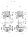
- FIG. 10 is a cross-sectional view taken along the lines X-X of FIG. 9 ;
- the holder 6 within the tiltable case 4 tilted by this rotation receives the rotational force of the main spindle through the shank 2 , the absorption rod 22 and the universal joint rod 5 and is rotated.
- the holder 6 is tilted together with the tiltable case 4 as shown in FIGS. 5 , 6 , the holder 6 is tilted around a central point of each of the spherical sliding bearings 34 , 43 on the lower side relative to the connecting portion with the universal joint rod 5 on the top end thereof and the universal joint rod 5 tilts around the vicinity of its intermediate point.
- the angular bearing is located between a bottom end portion of the shank 2 and the top portion of the outer case 3 as a first bearing 85 and this first bearing 85 is installed with preload applied using a cap screw 94 .
- An engaging groove 88 is formed along the axis in the side wall in the axial hole 21 provided in an axial position of the shank 2 and an outer peripheral portion of an absorption rod 82 fitted therein and engaging spheres 89 are fitted in the engaging groove 88 and the absorption rod 82 is installed in such a way that it is slidable only in the axial direction relative to the shank 2 by the engaging spheres 89 .
- the universal joint rod 105 is so constructed that the first universal joint portion 151 is formed at the top portion of an intermediate shaft while the second universal joint portion 152 is provided at the bottom of the intermediate shaft and penetrates through a central space in the pin case 131 .
- the first universal joint portion 151 at the top is fitted to the joint concave portion 124 in the absorption rod 122 and the second universal joint portion 152 at the bottom is fitted into the joint concave portion 163 at the upper portion of the holder main body 161 .
- the shank 102 is fitted to a recessed portion in the main spindle 110 of the machine tool and with the positioning pin 171 of the positional engaging portion 107 matched with the recessed portion in the bottom face of the positioning block 111 on the side of the machine tool spindle, the manual tool installation unit of the machine tool is operated so as to fix the shank 102 to the main spindle 110 .
- the shank 102 is coupled with the main spindle 110 of the machine tool so that the positioning pin 171 is fitted to the recessed portion in the bottom face of the positioning block 111 on the side of the machine tool spindle.
- the holder 106 can be tilted smoothly while maintaining a rapid rotation of the cutter 109 stably.
- the holder 106 and the cutter 109 can be returned to a linear state extremely smoothly without any vibration when the cutter 109 leaves the work piece W.
- the tilt supporting pin unit 130 is situated in a free state and then mounted through the second bearing 126 in a free state, the tilt supporting pin unit 130 moves smoothly in the circumferential direction when the holder is tilted so as to absorb the reaction of the tiltable case 104 thereby making it possible to return the holder 106 and the cutter 109 smoothly to a linear state.
Landscapes
- Engineering & Computer Science (AREA)
- Mechanical Engineering (AREA)
- Milling Processes (AREA)
- Milling, Broaching, Filing, Reaming, And Others (AREA)
- Jigs For Machine Tools (AREA)
- Finish Polishing, Edge Sharpening, And Grinding By Specific Grinding Devices (AREA)
- Grinding And Polishing Of Tertiary Curved Surfaces And Surfaces With Complex Shapes (AREA)
Applications Claiming Priority (2)
| Application Number | Priority Date | Filing Date | Title |
|---|---|---|---|
| JP2006-129379 | 2006-05-08 | ||
| JP2006129379A JP3868474B1 (ja) | 2006-05-08 | 2006-05-08 | 加工工具 |
Publications (2)
| Publication Number | Publication Date |
|---|---|
| US20070258782A1 US20070258782A1 (en) | 2007-11-08 |
| US7717653B2 true US7717653B2 (en) | 2010-05-18 |
Family
ID=37757021
Family Applications (1)
| Application Number | Title | Priority Date | Filing Date |
|---|---|---|---|
| US11/634,935 Expired - Fee Related US7717653B2 (en) | 2006-05-08 | 2006-12-07 | Processing tool |
Country Status (6)
| Country | Link |
|---|---|
| US (1) | US7717653B2 (zh) |
| JP (1) | JP3868474B1 (zh) |
| KR (1) | KR101376242B1 (zh) |
| CN (1) | CN101069952B (zh) |
| DE (1) | DE102007019515B4 (zh) |
| TW (1) | TWI413574B (zh) |
Cited By (7)
| Publication number | Priority date | Publication date | Assignee | Title |
|---|---|---|---|---|
| US20110138962A1 (en) * | 2008-08-12 | 2011-06-16 | Ntn Corporation | Remote-controlled actuator |
| US20110203825A1 (en) * | 2008-09-11 | 2011-08-25 | Ntn Corporation | Remote-controlled actuator |
| US20120067604A1 (en) * | 2009-05-29 | 2012-03-22 | Hiroshi Isobe | Remote-controlled actuator |
| US20130192059A1 (en) * | 2012-01-30 | 2013-08-01 | Heinrich Steger | Machining apparatus for grinding, milling, polishing or the like of a dental workpiece |
| WO2014153303A1 (en) * | 2013-03-16 | 2014-09-25 | Richards James L | Machining system |
| US20220126374A1 (en) * | 2020-10-27 | 2022-04-28 | Sugino Machine Limited | Deburring apparatus and deburring method |
| US11453067B2 (en) | 2018-03-15 | 2022-09-27 | Yih Troun Enterprise Co., Ltd. | Assembling and centering structure for processing tool |
Families Citing this family (28)
| Publication number | Priority date | Publication date | Assignee | Title |
|---|---|---|---|---|
| JP5500890B2 (ja) * | 2008-08-20 | 2014-05-21 | Ntn株式会社 | 遠隔操作型アクチュエータ |
| JP5500889B2 (ja) * | 2008-08-12 | 2014-05-21 | Ntn株式会社 | 遠隔操作型アクチュエータ |
| JP5500891B2 (ja) * | 2008-08-20 | 2014-05-21 | Ntn株式会社 | 遠隔操作型アクチュエータ |
| JP5213654B2 (ja) * | 2008-11-19 | 2013-06-19 | Ntn株式会社 | 遠隔操作型アクチュエータ |
| JP5202200B2 (ja) * | 2008-09-11 | 2013-06-05 | Ntn株式会社 | 遠隔操作型アクチュエータ |
| JP5464892B2 (ja) * | 2009-04-15 | 2014-04-09 | Ntn株式会社 | 遠隔操作型アクチュエータ |
| JP4714284B2 (ja) * | 2009-04-22 | 2011-06-29 | 豊岡エンジニアリング株式会社 | 切削装置 |
| CN103203636B (zh) * | 2012-01-16 | 2015-07-22 | 豪力辉工业股份有限公司 | 刀座用可调式离合器 |
| US9132521B2 (en) * | 2012-04-11 | 2015-09-15 | Kingsand Machinery Ltd. | Main shaft structure of tool machine |
| CN104108061A (zh) * | 2013-04-18 | 2014-10-22 | 上海辛帕工业自动化有限公司 | 自动铸件打磨工具 |
| JP6233833B2 (ja) * | 2013-07-23 | 2017-11-22 | 株式会社クロイツ | 面取回転工具 |
| CN103846793A (zh) * | 2014-03-25 | 2014-06-11 | 昆山艾思迪机械科技有限公司 | 砂轮主轴组件及包含其的磨床 |
| US20160067788A1 (en) * | 2014-09-06 | 2016-03-10 | James C. Brown | Adjustable Tool Holder |
| KR101572008B1 (ko) | 2015-09-18 | 2015-11-25 | 이상동 | 부하에 대한 자동조절 기능이 내장된 버 제거용 툴유닛 |
| CN107414631B (zh) * | 2017-08-17 | 2019-04-05 | 天津大学 | 大口径非球面机器人偏心式行星抛光装置 |
| DE102017123681C5 (de) * | 2017-10-11 | 2022-01-27 | Leitz Gmbh & Co. Kg | Fräswerkzeug zum Bearbeiten von Holz, Holzwerkstoffen, Kunststoffen oder Leichtmetallen |
| CN108908545A (zh) * | 2018-08-10 | 2018-11-30 | 林清吉 | 修边装置 |
| JP7088806B2 (ja) * | 2018-10-26 | 2022-06-21 | 株式会社スギノマシン | バリ取り工具およびバリ取り方法 |
| CN109760132B (zh) * | 2019-01-25 | 2020-12-04 | 杨松梅 | 一种新材料加工用穿孔设备 |
| JP7065055B2 (ja) * | 2019-05-07 | 2022-05-11 | 株式会社スギノマシン | バリ取り工具およびバリ取り方法 |
| CN111571318B (zh) * | 2020-04-16 | 2022-04-12 | 哈尔滨工业大学 | 一种单能量流驱动的回转冲击式超声波岩石磨削装置 |
| CN212553690U (zh) * | 2020-06-12 | 2021-02-19 | 米沃奇电动工具公司 | 摆动电动工具 |
| CN114433949B (zh) * | 2020-11-04 | 2024-05-14 | 杉野机械股份有限公司 | 去毛刺工具及去毛刺方法 |
| US20230130718A1 (en) * | 2021-01-27 | 2023-04-27 | Nihon Shoryoku Kikai Co., Ltd. | Deburring tool and deburring apparatus |
| CN113319327B (zh) * | 2021-06-01 | 2022-12-06 | 宿迁市宝利精密机械制造有限公司 | 一种斗轴的钻孔加工设备 |
| JP7090372B1 (ja) * | 2022-02-22 | 2022-06-24 | カトウ工機株式会社 | 加工工具 |
| CN114952842A (zh) * | 2022-05-27 | 2022-08-30 | 赛那德数字技术(上海)有限公司 | 基于抓取机械手的无序抓取方法、装置及存储介质 |
| CN115846707B (zh) * | 2023-03-02 | 2023-05-23 | 山东华云机电科技有限公司 | 金属表面加工刀具头装置 |
Citations (17)
| Publication number | Priority date | Publication date | Assignee | Title |
|---|---|---|---|---|
| US1357843A (en) * | 1919-09-19 | 1920-11-02 | John B Eader | Universal variable chuck |
| US1831382A (en) * | 1930-07-21 | 1931-11-10 | Gairing Tool Company | Full floating universal tool holder |
| US1860762A (en) * | 1928-11-02 | 1932-05-31 | Gairing Tool Company | Universal joint drive connection |
| US2468396A (en) * | 1946-04-26 | 1949-04-26 | Theodore E Frisco | Toolholder |
| US2475386A (en) * | 1945-05-04 | 1949-07-05 | Theodore E Frisco | Toolholder |
| US2527517A (en) * | 1947-09-11 | 1950-10-31 | Melvin A Barker | Automatic adjustable torque wrench |
| US2533758A (en) * | 1949-07-09 | 1950-12-12 | Scully Jones & Company | Floating holder |
| US2675242A (en) * | 1951-01-10 | 1954-04-13 | Gordon L Olson | Floating holder for tools |
| US2981544A (en) * | 1958-10-16 | 1961-04-25 | Scully Jones & Co | Floating holders |
| US3443818A (en) * | 1966-07-20 | 1969-05-13 | Bilz Otto | Quick-change chuck |
| JPH07328905A (ja) | 1994-06-13 | 1995-12-19 | Daishowa Seiki Co Ltd | バリ取り装置 |
| JPH0857758A (ja) | 1994-08-22 | 1996-03-05 | Daishowa Seiki Co Ltd | バリ取り装置 |
| JP2002052434A (ja) | 2000-08-16 | 2002-02-19 | Nakanishi:Kk | 工具駆動装置 |
| JP2004142064A (ja) | 2002-10-25 | 2004-05-20 | Kato Koki Kk | 加工工具 |
| CN1533864A (zh) | 2003-03-27 | 2004-10-06 | 住友重机械工业株式会社 | 夹紧装置及带倾斜功能的垂直方向驱动定位装置 |
| US6974286B2 (en) * | 2003-07-25 | 2005-12-13 | Ati Industrial Automation, Inc. | Deburring tool |
| JP2005349549A (ja) | 2004-06-14 | 2005-12-22 | Tsukasa Koki Kk | 加工工具 |
Family Cites Families (25)
| Publication number | Priority date | Publication date | Assignee | Title |
|---|---|---|---|---|
| JPS5541447Y2 (zh) * | 1975-04-08 | 1980-09-29 | ||
| JPS5355049U (zh) * | 1976-10-14 | 1978-05-11 | ||
| JPS5355049A (en) * | 1976-10-28 | 1978-05-19 | Nec Corp | Liquid crystal device |
| JPH01255720A (ja) * | 1988-03-31 | 1989-10-12 | Toshiharu Fujita | 自在継手 |
| JPH0665453B2 (ja) * | 1987-09-02 | 1994-08-24 | ヤマハ株式会社 | ロボット |
| JP2607166B2 (ja) * | 1990-04-20 | 1997-05-07 | 俊夫 藤平 | 家屋建築の基礎構築工法及び基礎構造並びに基礎構造用ユニット |
| JPH0721194B2 (ja) * | 1990-04-23 | 1995-03-08 | 鹿島建設株式会社 | 現場造成杭と基礎との一体化施工法 |
| JP2774181B2 (ja) * | 1990-04-23 | 1998-07-09 | 大成建設株式会社 | 地盤沈下による構造物の障害防止構法 |
| JPH045334U (zh) * | 1990-05-07 | 1992-01-17 | ||
| JPH088040Y2 (ja) * | 1990-05-07 | 1996-03-06 | 黒田精工株式会社 | 工具ホルダのハウジング装置 |
| JPH045333U (zh) * | 1990-05-07 | 1992-01-17 | ||
| JPH04111736A (ja) * | 1990-08-30 | 1992-04-13 | Hideo Mizoguchi | マシニングセンタの機械主軸用の工具構造 |
| JPH0526239U (ja) * | 1991-09-12 | 1993-04-06 | 大昭和精機株式会社 | 工具ホルダー |
| JPH0563740U (ja) * | 1992-02-04 | 1993-08-24 | 大昭和精機株式会社 | 工具ホルダー |
| JP3165763B2 (ja) * | 1993-09-03 | 2001-05-14 | 富士通株式会社 | ハンド保持装置 |
| JP2631266B2 (ja) * | 1994-03-31 | 1997-07-16 | 住友金属工業株式会社 | 伸縮軸継手 |
| JPH08184324A (ja) * | 1994-12-28 | 1996-07-16 | Akado Seisakusho:Kk | ユニバーサルジョイント |
| CN1189115A (zh) * | 1996-04-17 | 1998-07-29 | 鹫兴产株式会社 | 具有使加工装置倾斜的机构的加工机械 |
| JPH11303774A (ja) * | 1998-04-23 | 1999-11-02 | Tokico Ltd | スクロール式流体機械 |
| JP4929425B2 (ja) * | 2001-04-26 | 2012-05-09 | Smc株式会社 | コンプライアンスユニット |
| JP3942379B2 (ja) * | 2001-05-22 | 2007-07-11 | 信越ポリマー株式会社 | 精密基板収納容器の位置決め部材 |
| JP4054956B2 (ja) * | 2001-12-05 | 2008-03-05 | Smc株式会社 | コンプライアンスユニット |
| JP2003194145A (ja) * | 2001-12-28 | 2003-07-09 | Kajima Corp | ボール型免震支承用受け皿 |
| JP2005016084A (ja) * | 2003-06-24 | 2005-01-20 | Ebata Kk | 雨水貯留/貯留浸透槽 |
| TWM264043U (en) * | 2004-10-04 | 2005-05-11 | Sanjet Int Co Ltd | Knife cover with an engaging structure |
-
2006
- 2006-05-08 JP JP2006129379A patent/JP3868474B1/ja active Active
- 2006-12-07 US US11/634,935 patent/US7717653B2/en not_active Expired - Fee Related
-
2007
- 2007-04-18 TW TW096113573A patent/TWI413574B/zh not_active IP Right Cessation
- 2007-04-25 DE DE102007019515.1A patent/DE102007019515B4/de not_active Expired - Fee Related
- 2007-04-29 CN CN2007101011287A patent/CN101069952B/zh not_active Expired - Fee Related
- 2007-05-07 KR KR1020070043990A patent/KR101376242B1/ko not_active IP Right Cessation
Patent Citations (17)
| Publication number | Priority date | Publication date | Assignee | Title |
|---|---|---|---|---|
| US1357843A (en) * | 1919-09-19 | 1920-11-02 | John B Eader | Universal variable chuck |
| US1860762A (en) * | 1928-11-02 | 1932-05-31 | Gairing Tool Company | Universal joint drive connection |
| US1831382A (en) * | 1930-07-21 | 1931-11-10 | Gairing Tool Company | Full floating universal tool holder |
| US2475386A (en) * | 1945-05-04 | 1949-07-05 | Theodore E Frisco | Toolholder |
| US2468396A (en) * | 1946-04-26 | 1949-04-26 | Theodore E Frisco | Toolholder |
| US2527517A (en) * | 1947-09-11 | 1950-10-31 | Melvin A Barker | Automatic adjustable torque wrench |
| US2533758A (en) * | 1949-07-09 | 1950-12-12 | Scully Jones & Company | Floating holder |
| US2675242A (en) * | 1951-01-10 | 1954-04-13 | Gordon L Olson | Floating holder for tools |
| US2981544A (en) * | 1958-10-16 | 1961-04-25 | Scully Jones & Co | Floating holders |
| US3443818A (en) * | 1966-07-20 | 1969-05-13 | Bilz Otto | Quick-change chuck |
| JPH07328905A (ja) | 1994-06-13 | 1995-12-19 | Daishowa Seiki Co Ltd | バリ取り装置 |
| JPH0857758A (ja) | 1994-08-22 | 1996-03-05 | Daishowa Seiki Co Ltd | バリ取り装置 |
| JP2002052434A (ja) | 2000-08-16 | 2002-02-19 | Nakanishi:Kk | 工具駆動装置 |
| JP2004142064A (ja) | 2002-10-25 | 2004-05-20 | Kato Koki Kk | 加工工具 |
| CN1533864A (zh) | 2003-03-27 | 2004-10-06 | 住友重机械工业株式会社 | 夹紧装置及带倾斜功能的垂直方向驱动定位装置 |
| US6974286B2 (en) * | 2003-07-25 | 2005-12-13 | Ati Industrial Automation, Inc. | Deburring tool |
| JP2005349549A (ja) | 2004-06-14 | 2005-12-22 | Tsukasa Koki Kk | 加工工具 |
Non-Patent Citations (1)
| Title |
|---|
| Office Action dated Sep. 18, 2009, issued on the Chinese Patent Application No. 2007101011287 and English translation thereof. |
Cited By (12)
| Publication number | Priority date | Publication date | Assignee | Title |
|---|---|---|---|---|
| US20110138962A1 (en) * | 2008-08-12 | 2011-06-16 | Ntn Corporation | Remote-controlled actuator |
| US8393242B2 (en) * | 2008-08-12 | 2013-03-12 | Ntn Corporation | Remote-controlled actuator |
| US20110203825A1 (en) * | 2008-09-11 | 2011-08-25 | Ntn Corporation | Remote-controlled actuator |
| US8439899B2 (en) | 2008-09-11 | 2013-05-14 | Ntn Corporation | Remote-controlled actuator |
| US9446456B2 (en) | 2008-09-11 | 2016-09-20 | Ntn Corporation | Remote-controlled actuator |
| US20120067604A1 (en) * | 2009-05-29 | 2012-03-22 | Hiroshi Isobe | Remote-controlled actuator |
| US8939345B2 (en) * | 2009-05-29 | 2015-01-27 | Ntn Corporation | Remote-controlled actuator |
| US20130192059A1 (en) * | 2012-01-30 | 2013-08-01 | Heinrich Steger | Machining apparatus for grinding, milling, polishing or the like of a dental workpiece |
| US9009946B2 (en) * | 2012-01-30 | 2015-04-21 | Heinrich Steger | Machining apparatus for grinding, milling, polishing or the like of a dental workpiece |
| WO2014153303A1 (en) * | 2013-03-16 | 2014-09-25 | Richards James L | Machining system |
| US11453067B2 (en) | 2018-03-15 | 2022-09-27 | Yih Troun Enterprise Co., Ltd. | Assembling and centering structure for processing tool |
| US20220126374A1 (en) * | 2020-10-27 | 2022-04-28 | Sugino Machine Limited | Deburring apparatus and deburring method |
Also Published As
| Publication number | Publication date |
|---|---|
| TWI413574B (zh) | 2013-11-01 |
| TW200800499A (en) | 2008-01-01 |
| DE102007019515A1 (de) | 2007-11-15 |
| KR101376242B1 (ko) | 2014-03-21 |
| KR20070108820A (ko) | 2007-11-13 |
| DE102007019515B4 (de) | 2017-09-14 |
| JP2007301641A (ja) | 2007-11-22 |
| CN101069952A (zh) | 2007-11-14 |
| CN101069952B (zh) | 2011-07-20 |
| JP3868474B1 (ja) | 2007-01-17 |
| US20070258782A1 (en) | 2007-11-08 |
Similar Documents
| Publication | Publication Date | Title |
|---|---|---|
| US7717653B2 (en) | Processing tool | |
| JP4665440B2 (ja) | 加工工具 | |
| US5156382A (en) | Workpiece support having locking mechanism | |
| JP2023178392A (ja) | バリ取り工具 | |
| US4086704A (en) | Combination tool mount and centering device | |
| US20030165367A1 (en) | Hand-held milling machine | |
| JPH0357413Y2 (zh) | ||
| JP3203023U (ja) | バリ取り装置 | |
| TW200533462A (en) | Workpiece holding vice | |
| JP6363773B1 (ja) | 加工工具 | |
| JP2008284677A (ja) | 加工工具 | |
| JP6763504B2 (ja) | 位置補正機能付き作業機械及びその位置補正方法。 | |
| US9427810B2 (en) | Tool holder | |
| JPS6384836A (ja) | 切削工具駆動装置 | |
| JPH08243929A (ja) | 研磨工具 | |
| JPH0724964B2 (ja) | 超精密仕上用ユニバーサルチヤック装置 | |
| JP4064014B2 (ja) | 口金 | |
| JPS639367Y2 (zh) | ||
| JPH03178725A (ja) | フローティングホルダ | |
| JP2001138194A (ja) | ガラス板加工機の面取り装置 | |
| JP4638777B2 (ja) | 緩み止め特殊ナットの旋削加工方法 | |
| JP2022096809A (ja) | 調芯機構および同機構を備えた自動締結機 | |
| JPH0526211U (ja) | ワンタツチ形工具ホルダ及びストレートシヤンク付回転工具 | |
| JPH06155113A (ja) | 切削加工用工具 | |
| JP5865295B2 (ja) | 工作機械に使用されるワーク押圧具 |
Legal Events
| Date | Code | Title | Description |
|---|---|---|---|
| AS | Assignment |
Owner name: TSUKASA MACHINE INDUSTRY CO., LTD., JAPAN Free format text: ASSIGNMENT OF ASSIGNORS INTEREST;ASSIGNORS:MIYATA, YOSHIHIRO;MIZUMUKAI, MAKOTO;REEL/FRAME:018681/0718 Effective date: 20061120 Owner name: TSUKASA MACHINE INDUSTRY CO., LTD.,JAPAN Free format text: ASSIGNMENT OF ASSIGNORS INTEREST;ASSIGNORS:MIYATA, YOSHIHIRO;MIZUMUKAI, MAKOTO;REEL/FRAME:018681/0718 Effective date: 20061120 |
|
| FPAY | Fee payment |
Year of fee payment: 4 |
|
| FEPP | Fee payment procedure |
Free format text: MAINTENANCE FEE REMINDER MAILED (ORIGINAL EVENT CODE: REM.) |
|
| LAPS | Lapse for failure to pay maintenance fees |
Free format text: PATENT EXPIRED FOR FAILURE TO PAY MAINTENANCE FEES (ORIGINAL EVENT CODE: EXP.) |
|
| STCH | Information on status: patent discontinuation |
Free format text: PATENT EXPIRED DUE TO NONPAYMENT OF MAINTENANCE FEES UNDER 37 CFR 1.362 |
|
| FP | Lapsed due to failure to pay maintenance fee |
Effective date: 20180518 |